EP3865683B1 - Ensemble d'étanchéité pour moteur à turbine à gaz avec agencement de charge à pression réduite - Google Patents
Ensemble d'étanchéité pour moteur à turbine à gaz avec agencement de charge à pression réduite Download PDFInfo
- Publication number
- EP3865683B1 EP3865683B1 EP21156979.3A EP21156979A EP3865683B1 EP 3865683 B1 EP3865683 B1 EP 3865683B1 EP 21156979 A EP21156979 A EP 21156979A EP 3865683 B1 EP3865683 B1 EP 3865683B1
- Authority
- EP
- European Patent Office
- Prior art keywords
- region
- arc segment
- assembly
- backside
- seal arc
- Prior art date
- Legal status (The legal status is an assumption and is not a legal conclusion. Google has not performed a legal analysis and makes no representation as to the accuracy of the status listed.)
- Active
Links
Images





Classifications
-
- F—MECHANICAL ENGINEERING; LIGHTING; HEATING; WEAPONS; BLASTING
- F01—MACHINES OR ENGINES IN GENERAL; ENGINE PLANTS IN GENERAL; STEAM ENGINES
- F01D—NON-POSITIVE DISPLACEMENT MACHINES OR ENGINES, e.g. STEAM TURBINES
- F01D11/00—Preventing or minimising internal leakage of working-fluid, e.g. between stages
- F01D11/08—Preventing or minimising internal leakage of working-fluid, e.g. between stages for sealing space between rotor blade tips and stator
-
- F—MECHANICAL ENGINEERING; LIGHTING; HEATING; WEAPONS; BLASTING
- F01—MACHINES OR ENGINES IN GENERAL; ENGINE PLANTS IN GENERAL; STEAM ENGINES
- F01D—NON-POSITIVE DISPLACEMENT MACHINES OR ENGINES, e.g. STEAM TURBINES
- F01D25/00—Component parts, details, or accessories, not provided for in, or of interest apart from, other groups
- F01D25/24—Casings; Casing parts, e.g. diaphragms, casing fastenings
- F01D25/246—Fastening of diaphragms or stator-rings
-
- F—MECHANICAL ENGINEERING; LIGHTING; HEATING; WEAPONS; BLASTING
- F05—INDEXING SCHEMES RELATING TO ENGINES OR PUMPS IN VARIOUS SUBCLASSES OF CLASSES F01-F04
- F05D—INDEXING SCHEME FOR ASPECTS RELATING TO NON-POSITIVE-DISPLACEMENT MACHINES OR ENGINES, GAS-TURBINES OR JET-PROPULSION PLANTS
- F05D2230/00—Manufacture
- F05D2230/60—Assembly methods
- F05D2230/64—Assembly methods using positioning or alignment devices for aligning or centring, e.g. pins
- F05D2230/642—Assembly methods using positioning or alignment devices for aligning or centring, e.g. pins using maintaining alignment while permitting differential dilatation
-
- F—MECHANICAL ENGINEERING; LIGHTING; HEATING; WEAPONS; BLASTING
- F05—INDEXING SCHEMES RELATING TO ENGINES OR PUMPS IN VARIOUS SUBCLASSES OF CLASSES F01-F04
- F05D—INDEXING SCHEME FOR ASPECTS RELATING TO NON-POSITIVE-DISPLACEMENT MACHINES OR ENGINES, GAS-TURBINES OR JET-PROPULSION PLANTS
- F05D2240/00—Components
- F05D2240/10—Stators
- F05D2240/11—Shroud seal segments
-
- F—MECHANICAL ENGINEERING; LIGHTING; HEATING; WEAPONS; BLASTING
- F05—INDEXING SCHEMES RELATING TO ENGINES OR PUMPS IN VARIOUS SUBCLASSES OF CLASSES F01-F04
- F05D—INDEXING SCHEME FOR ASPECTS RELATING TO NON-POSITIVE-DISPLACEMENT MACHINES OR ENGINES, GAS-TURBINES OR JET-PROPULSION PLANTS
- F05D2300/00—Materials; Properties thereof
- F05D2300/60—Properties or characteristics given to material by treatment or manufacturing
- F05D2300/603—Composites; e.g. fibre-reinforced
- F05D2300/6033—Ceramic matrix composites [CMC]
-
- Y—GENERAL TAGGING OF NEW TECHNOLOGICAL DEVELOPMENTS; GENERAL TAGGING OF CROSS-SECTIONAL TECHNOLOGIES SPANNING OVER SEVERAL SECTIONS OF THE IPC; TECHNICAL SUBJECTS COVERED BY FORMER USPC CROSS-REFERENCE ART COLLECTIONS [XRACs] AND DIGESTS
- Y02—TECHNOLOGIES OR APPLICATIONS FOR MITIGATION OR ADAPTATION AGAINST CLIMATE CHANGE
- Y02T—CLIMATE CHANGE MITIGATION TECHNOLOGIES RELATED TO TRANSPORTATION
- Y02T50/00—Aeronautics or air transport
- Y02T50/60—Efficient propulsion technologies, e.g. for aircraft
Definitions
- This disclosure relates to cooling of gas turbine engine components.
- the invention relates to a seal assembly for a gas turbine engine.
- Gas turbine engines can include a fan for propulsion air and to cool components.
- the fan also delivers air into a core engine where it is compressed.
- the compressed air is then delivered into a combustion section, where it is mixed with fuel and ignited.
- the combustion gas expands downstream over and drives turbine blades.
- Static vanes are positioned adjacent to the turbine blades to control the flow of the products of combustion.
- the turbine section may include multiple stages of rotatable blades and static vanes.
- An annular shroud or blade outer air seal may be provided around the blades in close radial proximity to the tips of the blades to reduce the amount of gas flow that escapes around the blades.
- the shroud typically includes a plurality of arc segments that are circumferentially arranged about the blades and mounted to support structure.
- Pressurized cooling air may be utilized to cool the shroud.
- US 20170175572 A1 describes a turbine shroud adapted for use in a gas turbine engine including a plurality of metallic carrier segments and a plurality of blade track segments mounted to corresponding metallic carrier segments.
- US 20100104426 A1 describes a ring seal for a turbine engine.
- the ring seal can be made up of a plurality of circumferentially abutted ring seal segments.
- seal assembly for a gas turbine engine as recited in claim 1.
- the seal arc segment comprises a ceramic material.
- the seal arc segment includes a plurality of ply layers in stacked relationship that establish a backside cavity between the first and second rails along the second region.
- the plurality of ply layers are radiused at interfaces between the sealing portion and the respective first and second rails.
- a backside cavity is established between the first and second rails.
- a radially facing component of a total surface area of the backside cavity is divided by the radially facing component of the total surface area of the second region is equal to or less than 0.2.
- a radially facing component of a total surface area of the first and second edge faces is divided by the radially facing component of the total surface area of the first region is equal to or less than 0.5.
- the load ratio is equal to or greater than 0.2, and is equal to or less than 0.4.
- a further embodiment of any of the foregoing embodiments includes a support that has a mounting portion and an interface portion.
- the mounting portion is attachable to an engine static structure, and the retention pin is dimensioned to engage the interface portion of the support to mount the seal arc segment.
- a support plate is releasably secured to the support such that the retention pin is trapped between the support and the support plate in an installed position.
- the seal arc segment includes a ceramic matrix composite material.
- a cooling cavity is established such that a perimeter of the cooling cavity is bounded by the support, the support plate, and the backside face between the first and second rails.
- the cooling cavity is coupled to a fluid source that conveys pressurized cooling flow to the cooling cavity in operation such that a fluid pressure in the cooling cavity along the first region is greater than a fluid pressure across the first cantilevered section and is greater than a fluid pressure across the second cantilevered section.
- surfaces of the first and second rails slope towards the backside face.
- the backside face includes a plurality of undulations between the first and second rails.
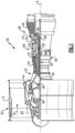
- FIG. 1 schematically illustrates a gas turbine engine 20.
- the gas turbine engine 20 is disclosed herein as a two-spool turbofan that generally incorporates a fan section 22, a compressor section 24, a combustor section 26 and a turbine section 28.
- the fan section 22 drives air along a bypass flow path B in a bypass duct defined within a housing 15 such as a fan case or nacelle, and also drives air along a core flow path C for compression and communication into the combustor section 26 then expansion through the turbine section 28.
- the exemplary engine 20 generally includes a low speed spool 30 and a high speed spool 32 mounted for rotation about an engine central longitudinal axis A relative to an engine static structure 36 via several bearing systems 38. It should be understood that various bearing systems 38 at various locations may alternatively or additionally be provided, and the location of bearing systems 38 may be varied as appropriate to the application.
- the low speed spool 30 generally includes an inner shaft 40 that interconnects, a first (or low) pressure compressor 44 and a first (or low) pressure turbine 46.
- the inner shaft 40 is connected to the fan 42 through a speed change mechanism, which in exemplary gas turbine engine 20 is illustrated as a geared architecture 48 to drive a fan 42 at a lower speed than the low speed spool 30.
- the high speed spool 32 includes an outer shaft 50 that interconnects a second (or high) pressure compressor 52 and a second (or high) pressure turbine 54.
- a combustor 56 is arranged in exemplary gas turbine 20 between the high pressure compressor 52 and the high pressure turbine 54.
- a mid-turbine frame 57 of the engine static structure 36 may be arranged generally between the high pressure turbine 54 and the low pressure turbine 46.
- the mid-turbine frame 57 further supports bearing systems 38 in the turbine section 28.
- the inner shaft 40 and the outer shaft 50 are concentric and rotate via bearing systems 38 about the engine central longitudinal axis A which is colline
- the core airflow is compressed by the low pressure compressor 44 then the high pressure compressor 52, mixed and burned with fuel in the combustor 56, then expanded over the high pressure turbine 54 and low pressure turbine 46.
- the mid-turbine frame 57 includes airfoils 59 which are in the core airflow path C.
- the turbines 46, 54 rotationally drive the respective low speed spool 30 and high speed spool 32 in response to the expansion.
- gear system 48 may be located aft of the low pressure compressor, or aft of the combustor section 26 or even aft of turbine section 28, and fan 42 may be positioned forward or aft of the location of gear system 48.
- the engine 20 in one example is a high-bypass geared aircraft engine.
- the engine 20 bypass ratio is greater than about six (6), with an example embodiment being greater than about ten (10)
- the geared architecture 48 is an epicyclic gear train, such as a planetary gear system or other gear system, with a gear reduction ratio of greater than about 2.3
- the low pressure turbine 46 has a pressure ratio that is greater than about five.
- the engine 20 bypass ratio is greater than about ten (10:1)
- the fan diameter is significantly larger than that of the low pressure compressor 44
- the low pressure turbine 46 has a pressure ratio that is greater than about five 5:1.
- Low pressure turbine 46 pressure ratio is pressure measured prior to inlet of low pressure turbine 46 as related to the pressure at the outlet of the low pressure turbine 46 prior to an exhaust nozzle.
- the geared architecture 48 may be an epicycle gear train, such as a planetary gear system or other gear system, with a gear reduction ratio of greater than about 2.3:1 and less than about 5:1. It should be understood, however, that the above parameters are only exemplary of one embodiment of a geared architecture engine and that the present invention is applicable to other gas turbine engines including direct drive turbofans.
- the fan section 22 of the engine 20 is designed for a particular flight condition -- typically cruise at about 0.8 Mach and about 35,000 feet (10,668 meters).
- the flight condition of 0.8 Mach and 35,000 ft (10,668 meters), with the engine at its best fuel consumption - also known as "bucket cruise Thrust Specific Fuel Consumption ('TSFC')" - is the industry standard parameter of lbm of fuel being burned divided by lbf of thrust the engine produces at that minimum point.
- "Low fan pressure ratio” is the pressure ratio across the fan blade alone, without a Fan Exit Guide Vane (“FEGV”) system.
- the low fan pressure ratio as disclosed herein according to one non-limiting embodiment is less than about 1.45.
- Low corrected fan tip speed is the actual fan tip speed in ft/sec divided by an industry standard temperature correction of [(Tram °R) / (518.7 °R)] 0.5 .
- the "Low corrected fan tip speed” as disclosed herein according to one non-limiting embodiment is less than about 1150 ft / second (350.5 meters/second).
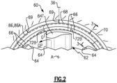
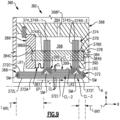
- Figure 2 illustrates an axial view of an example assembly 60 for a gas turbine engine.
- the assembly 60 can be incorporated into a portion of the engine 20 of Figure 1 , such as the turbine section 28.
- the assembly 60 is a blade outer air seal assembly for sealing portions of a gas turbine engine.
- the assembly 60 can alternatively or additionally be adapted for other portions of the engine 20, such as an upstream stage of the compressor section 24 or combustor panels defining portions of a combustion chamber located in the combustor section 26.
- teachings herein primarily refer to a two-spool gas turbine engine having a fan, other systems can benefit from the teachings herein, such as engines without a fan and other ground based systems.
- the assembly 60 is positioned radially outward of a rotor 62 having an array (or row) of airfoils or rotatable blades 64.
- the blades 64 are rotatable about the engine longitudinal axis A in a gas path GP, such as the core flow path C ( Figure 1 ).
- the blades 64 are positioned adjacent to one or more rows of vanes that direct flow in the gas path GP towards the blades 64.
- the assembly 60 includes one or more gas turbine engine components 66.
- the components 66 are blade outer air seals (BOAS) or seal arc segments.
- the assembly 60 includes an array of seal arc segments 66 circumferentially arranged in an annulus around the engine longitudinal axis A and about the blades 64.
- the seal arc segments 66 are mounted to at least one support 68, which can be continuous or can be segmented as a plurality of supports (illustrated by dashed lines in Figure 2 ).
- the support 68 is mounted or attached to an engine case 70 through one or more connections 69.
- the engine case 70 provides a portion of the engine static structure 36 ( Figure 1 ).
- the engine case 70 is arranged about and extends along the engine axis A.
- the seal arc segments 66 are directly attached to the engine case 70.
- the engine case 70 can be mounted or attached to, or form a portion of, the engine static structure 36 (see also Figure 1 ).
- Each seal arc segment 66 can be formed of a material having a high temperature capability.
- Example high temperature materials include metallic alloys and ceramic-based materials, such as a monolithic ceramic or a ceramic matrix composite (CMC) material.
- An example of a high temperature metallic alloy is a nickel-based alloy.
- Monolithic ceramics include, but are not limited to, silicon carbide (SiC) or silicon nitride (Si 3 N 4 ).
- each seal arc segment 66 is formed of high-toughness material such as, but not limited to, single crystal metallic alloys.
- the seal arc segments 66 are positioned in close radial proximity to tips 64T of the blades 64 to reduce the amount of gas flow that escapes around the blades 64 and through a clearance gap G.
- the engine 20 can include an active or passive clearance control system to adjust the clearance gap G to a desired dimension during one or more operating conditions of the engine 20.
- the clearance gap G may also vary during operation of the engine 20, such as between a non-operating, cold state condition, and an operating condition such as a cruise and/or takeoff condition of the engine 20.
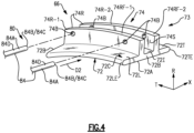
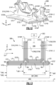
- FIG 4 illustrates a perspective view of an example seal arc segment 66.
- the seal arc segment 66 is arranged about the longitudinal axis A to bound the gas path GP.
- Each seal arc segment 66 includes a sealing portion 72 and a seal interface portion 74 along a backside 73 of the seal arc segment 66.
- the sealing portion 72 includes a generally arcuate sealing face (or surface) 72A extending in a circumferential (or thickness) direction T between circumferential mate faces 72B and extending in an axial direction X between a leading edge 72LE and a trailing edge 72TE, as illustrated by Figure 4 (see also Figure 2 ).
- the axial direction X can be parallel or substantially parallel to the longitudinal axis A.
- the sealing face 72A is dimensioned to bound portions of the gas path GP, such as the core flow path C of Figure 1 .
- the backside face 73 is radially opposed to the sealing face 72A.
- the sealing face 72A can face radially inward and the backside face 73 faces radially outward relative to the longitudinal axis A when the seal arc segment 66 is in an installed position, as illustrated by Figure 3 .
- the first interface portion 74 of the seal arc segment 66 includes a pair of opposed first and second rails 74R (indicated at 74R-1, 74R-2) extending radially outwardly in a radial direction R from the sealing portion 72 to respective first and second edge faces 74RF (indicated at 74RF-1, 74RF-2).
- An elongated slot or backside cavity 74S is established between the rails 74R.
- the seal arc segment 66, including at least the sealing portion 72 and/or rails 74R of the seal interface portion 74 can be made of any of the materials disclosed herein, including a ceramic-based material such as a CMC material.
- the sealing portion 72 of the seal arc segment 66 includes a backside face (or surface) 72C radially opposed to the sealing face 72A.
- the backside face 72C extends along the backside 73 of the seal arc segment 66.
- the sealing portion 72 includes a leading edge (or first cantilevered) extension or section 72L, a trailing edge (or second cantilevered) extension or section 72T, and an intermediate (or third) section 721 interconnecting the leading edge and trailing edge sections 72L, 72T.
- the leading edge section 72L extends in the axial direction X between the first rail 74R-1 and the leading edge 72LE
- the trailing edge section 72T extends in the axial direction X between the second rail 74R-2 and the trailing edge 72TE.
- the intermediate section 721 extends in the axial direction X between the leading and trailing edge sections 72L, 72T and between the rails 74R relative to the longitudinal axis A.
- the leading edge and trailing edge sections 72L, 72T are cantilevered from the intermediate section 721.
- the backside face 72C includes a first (or leading edge) localized region LR1 along the leading edge section 72L between the leading edge 72LE and the first rail 74R-1, a second (or intermediate) localized region LR2 between the pair of rails 74R, and a third (or trailing edge) localized region LR3 along the trailing edge section 72T between the second rail 74R-2 and the trailing edge 72TE.
- the first and second rails 74R-1, 74R-2 are dimensioned to extend in the circumferential direction T between the opposed mate faces 72B of the seal arc segment 66 to divide the backside face 72C into the first localized region LR1, the second localized region LR2, and the third localized region LR3.
- the support 68 includes a mounting portion 76, a first interface portion 78 and a second interface portion 79, which can be made of a metallic material.
- the mounting portion 76 is attachable to the engine static structure 36 directly or through the engine case 70.
- the interface portions 78, 79 are flanges that extending radially inwardly from the mounting portion 76 in a direction towards the longitudinal axis A.
- the support 68 includes a support cavity 77 established between the interface portions 78, 79.
- the support cavity 77 is dimensioned to at least partially receive the rails 74R.
- the assembly 60 includes a retention feature 80 that mounts the seal arc segments 66 to the support 68 during engine operation.
- the retention feature 80 is dimensioned to carry the seal arc segment 66 in an installed position.
- the retention feature 80 is dimensioned to establish and maintain a predetermined distance between the sealing face 72A of the seal arc segments 66 and the blade tips 64T across the clearance gap G.
- the retention feature 80 can be arranged to releasably secure the seal interface portion 74 to the support 68.
- Example retention features include flanges, fasteners such as clips, pins, bolts and rivets, as well as other components that mechanically join objects together such as a length of wire.
- the retention feature 80 includes one or more retention pins (or members) 84 releasably secured to the seal arc segment(s) 66.
- Each retention pin 84 is dimensioned to engage the first and/or second interface portions 78, 79 of the support 68 and the rail(s) 74R of the seal interface portion 74 of a respective one of the seal arc segments 66 such that each of the seal arc segments 66 is carried by one or more of the retention pins 84 to mount the seal arc segments 66 in the installed position.
- the seal arc segment 66, support 68 and retention pins 84 are separate and distinct components. In the illustrative example of Figure 4 , two retention pins 84 are utilized to mount each seal arc segment 66.
- Each retention pin 84 includes an elongated main body 84A extending between opposed first and second end portions 84B, 84C.
- the retention pin 84 can be dimensioned to span between the first and second interface portions 78, 79, as illustrated in Figure 3 .
- the main body 84A of the retention pin 84 can have various geometries, such as a circular or otherwise elliptical cross sectional geometry as illustrated by Figures 3-4 .
- Other example geometries of the retention pin 84 can include triangular, rectangular and complex cross sectional geometries.
- the seal interface portion 74 includes one or more interface bores 74B extending through a respective rail 74R.
- Each interface bore 74B of the rail 74R-1 is partially or completely radially aligned in the radial direction R with a respective interface bore 74B of the rail 74R-2, as illustrated by Figure 3 .
- the rails 74R establish respective attachment points along the interface bores 74B dimensioned to engage a respective retention pin 84 for mounting the seal arc segment 66 to the support 68.
- Each interface bore 74B can have a diameter that is greater than or equal to a diameter of a respective one of the retention pins 84.
- the interface bores 74B can be dimensioned to have a relatively greater diameter to accommodate differences in thermal expansion of the rails 74R, retention pins 84 and/or support 68 during engine operation. Utilizing the retention pins 84 to mounting the seal arc segments 66 may more evenly distribute loads and reduce localized stress concentrations in the rails 74R adjacent the attachment points.
- the first and second interface portions 78, 79 includes one or more respective support bores 78B, 79B (one of each shown in Figure 3 for illustrative purposes). Each pair of interface bores 74B and pair of support bores 78B, 79B is dimensioned to at least partially receive a common retention pin 84 to establish the installed position of the seal arc segment 66.
- each interface bore 74B is partially or completely radially aligned in the radial direction R with an adjacent support bore 78B.
- Each retention pin 84 is slidably received in, and extends at least partially through, the support bore 79B and the interface bore 74B of each rail 74R-1, 74R-2 and is received in a respective support bore 78B to secure the interface portion 74 to the support 68 in the installed position.
- Each interface bore 74B is dimensioned to receive a respective retention pin 84 such the rails 74R of the seal arc segment 66 are carried by an outer periphery 84D of the retention pin(s) 84 in the installed position.
- each rail 74R are dimensioned to receive a respective retention pin 84 such that the rails 74R of the seal arc segment 66 sit on an outer periphery or radially outer surface 84RO of the retention pin 84, as illustrated by Figure 3 .
- the assembly 60 includes a support plate 86 releasably attached or secured to the support 68.
- Various techniques can be utilized to secure the support plate 86 to the support 68, such as one or more fasteners.
- the support plate 86 includes a plate body 86A having a generally arcuate geometry and extends about the engine longitudinal axis A.
- the support plate 86 can be a single component or can include one or more segments mechanically attached to each other.
- the support plate 86 includes a plate flange 86F extending outwardly from the plate body 86A.
- the plate flange 86F is dimensioned to extend along an inner diameter 86ID of the support plate 86.
- the support 68, support plate 86 and retention pins 84 can be made of a high temperature metal or metal alloy, for example.
- the support plate 86 can be arranged or positioned relative to the support 68 such that the retention pin(s) 84 are trapped between the support plate 86 and support 68 in the installed position, as illustrated in Figure 3 .
- the first end portion 84B of the retention pin 84 is at least partially inserted into the respective support bore 78B, and the second end portion 84C of the retention pin 84 is dimensioned to abut against the plate body 86A of the support plate 86 such that the support plate 86 limits axial movement of the retention pin(s) 84 relative to the longitudinal axis A.
- Various techniques can be utilized to secure the retention pin 84 to the support 68, such as press fitting or threadedly attaching the retention pin 84 in the support bore 78B.
- the second interface portion 79 of the support 68 is axially opposed to the first interface portion 78 relative to the longitudinal axis A such that the second interface portion 79 is situated between the support plate 86 and the first interface portion 78.
- the seal arc segments 66 can be subject to hot gases communicated in the adjacent gas path GP during engine operation.
- the assembly 60 establishes a cooling arrangement or scheme 92 operable to cool the seal arc segment(s) 66 and adjacent portions of the assembly 60 during engine operation.
- Various cooling schemes 92 may be utilized, including any of the cooling schemes in combination with any of the assemblies disclosed herein.
- the cooling scheme 92 includes at least one feeding plenum (or cavity) 94 and cooling cavity 96.
- the feeding plenum 94 can be defined by an engine static structure such as the engine case 70 or another portion of the engine static structure 36.
- the plenum 94 and cooling cavity 96 generally extend in the circumferential direction T about the longitudinal axis A.
- the plenum 94 is established between the engine case 70 and support 68.
- the plenum 94 is fluidly coupled to one or more coolant (or fluid) sources CS (one shown in dashed lines for illustrative purposes).
- the coolant source CS is configured to supply cooling air or fluid flow CF to the plenum 94.
- the plenum 94 is configured to receive the pressurized cooling flow CF from the cooling source(s) CS to cool portions of the assembly 60 including the seal arc segment(s) 66, support 68 and/or engine case 70 during engine operation.
- Coolant sources CS can include bleed air from an upstream stage of the compressor section 24 ( Figure 1 ), bypass air, or a secondary cooling system aboard the aircraft, for example.
- the cooling cavity 96 is established along surfaces of the seal arc segment(s) 66.
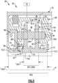
- the cooling cavity 96 is established in the radial direction R between the support 68 and the backside face 72C such that the second localized region LR2 bounds the cooling cavity 96.
- the cooling cavity 96 is established in the axial direction X between the first and second rails 74R-1, 74R-2 relative to the engine longitudinal axis A.
- the cooling cavity 96 is established such a perimeter of the cooling cavity 96 is bounded by the support 68, support plate 86, and the second localized region LR2 of the backside face 72C between the rails 74R and along the intermediate section 721 of the seal arc segment 66.
- the assembly 60 can include a seal member 87 captured between the first rail 74R-1 of the seal arc segment 66 and the plate flange 86F of the support plate 86 to bound the perimeter of the cooling cavity 96 adjacent to the first localized region LR1 along the leading edge section 72L.
- the seal member 87 is arranged to fluidly isolate the leading edge section 72L from the cooling cavity 96.
- the seal member 87 can incorporate various seal configurations. In the illustrative example of Figure 3 , the seal member 87 is a W-seal arranged to oppose flow along an axial gap between the seal arc segment 66 and support plate 86.
- the first interface portion 78 of the support 68 can be dimensioned to abut the second rail 74R-2 to bound the perimeter of the cooling cavity 96.
- the support 68 includes at least one face seal 90 dimensioned to engage the interface portion 74 directly or along the second rail 74R-2.
- the face seal 90 is dimensioned to oppose fluid flow along an axial gap between the seal interface portion 74 and first interface portion 78 of the support 68.
- the face seal 90 is dimensioned to bound the perimeter of the cooling cavity 96 adjacent to the third localized region LR3.
- the cooling scheme 92 can include at least one feeding passage 68P and at least one cooling passage 86P arranged to convey pressurized cooling flow CF between the coolant source CS and portions of the seal arc segment(s) 66.
- Each feeding passage 68P interconnects the cooling cavity 96 and the coolant source CS to convey pressurized cooling flow CF to the cooling cavity 96 in operation.
- Each feeding passage 68P is arranged to convey a portion of the cooling flow CF to the backside cavity 74S to cool adjacent portions of the seal arc segment 66.
- One or more cooling passages 86P can be arranged at different positions than the feeding passages 68P to convey localized cooling flow CF to surfaces of the seal arc segment(s) 66.
- the support plate 86 defines one or more cooling passages 86P fluidly coupled to the cooling cavity 96.
- Each cooling passage 86P is oriented to convey cooling flow CF from the cooling cavity 96 in a direction towards the leading edge section 72L, for example.
- CMC-based seal arc segments 66 may have relative lower stress margins and may have a much lower ductility than typical metal.
- Pressurized cooling flow CF communicated to the cooling cavity 96 may be utilized to cool portions of the seal arc segments 66 and may be delivered to intersegment gaps between mate faces 72C of adjacent seal arc segments 66 to reduce a likelihood of ingestion of hot gases in the gas path GP.
- the pressurized cooling flow CF may subject the seal arc segments 66 to relatively high radial pressure loading on the attachment points or interfaces between the rails 74R and retention pins 84. Because CMC material can be relatively stiff, the attachment surfaces may not be very compliant and may have relatively small contact areas that communicate the radial pressure loads to the support structure.
- the disclosed seal arc segments, including the seal arc segments 66 are dimensioned to establish a complete gas path surface and a reduced pressure load arrangement having a reduced backside surface area exposed to the pressurizing cooling flow CF during engine operation.
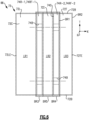
- each seal arc segment 66 is dimensioned to establish a first backside region BR1 and a second backside region BR2 along the backside 73 of the seal arc segment 66 radially opposed to the sealing face 72A (shown in dashed lines in Figure 6 for illustrative purposes).
- the first backside region BR1 is inclusive of a portion of the backside face 72C, including the second localized region LR2.
- the first backside region BR1 spans a first length L BR1 in the axial direction X ( Figure 5 ).
- the second backside region BR2 is established along the leading and trailing edge sections 72L, 72T cantilevered from the intermediate section 721, with the second region BR2 inclusive of the first backside region BR1 and an entirety of the backside face 72C including the localized regions LR1-LR3.
- the second backside region BR2 spans a second length L BR2 in the axial direction X ( Figure 5 ).
- a ratio of the first length L BR1 to the second length L BR2 is equal to or less than 1.0.
- the ratio of the first length L BR1 to the second length L BR2 is equal to or less than 0.5, or more narrowly equal to or greater than 0.2. In further examples, the ratio of the first length L BR1 to the second length L BR2 is equal to or less than 0.4. The ratio of the first length L BR1 to the second length L BR2 can be greater than 0.5. In examples, the ratio of the first length L BR1 to the second length L BR2 is equal to or greater than 0.6 and is less than or equal to 0.9.
- the rails 74R of each seal arc segment 66 are dimensioned to establish third, fourth and fifth backside regions BR3-BR5 along the backside 73 of the seal arc segment 66 (shown in dashed lines in Figure 6 for illustrative purposes).
- the third backside region BR3 is established by surfaces of the first rail 74R-1 between the leading edge section 72L and the intermediate section 72I in the axial direction X and between the mate faces 72B in the circumferential direction T, inclusive of the first edge face 74RF-1.
- the fourth backside region BR4 is established by surfaces of the second rail 74R-2 between the trailing edge section 72T and the intermediate section 72I in the axial direction X and between the mate faces 72B in the circumferential direction T, inclusive of the second edge face 74RF-2.
- the fifth backside region BR5 is established by surfaces of the backside cavity 74S between the first and second rails 74R-1, 74R-2.
- the surface area of the first backside region BR1 is equal to the surface area of the third, fourth and fifth backside regions BR3-BR5.
- Surfaces of the seal arc segment 66 can be subject to various pressure loads along the regions BR1-BR5 during engine operation.
- the regions BR1-BR5 can be dimensioned to reduce radial loading caused by pressurized fluid communicated in the gas path GP and/or cooling cavity 96 and associated pressure differentials established across the seal arc segment 66.
- the first load ratio can be equal to or less than 1.0. In examples, the first load ratio is equal to or less than 0.5. In further examples, the first load ratio is equal to or greater than 0.2, or more narrowly is equal to or less than 0.4, such as approximately 0.33. The first load ratio can be greater than 0.5. In examples, the first load ratio is equal to or greater than 0.6 and is less than or equal to 0.9.
- the backside 73 of the seal arc segment 66 can be dimensioned to reduce radial loading that may occur due to exposure of pressurized cooling flow CF in the cooling cavity 96.
- a backside surface region BRS of the seal arc segment 66 is established along surfaces of the seal arc segment 66 exposed to the cooling cavity 96.
- the first backside region BR1 and the backside surface region BRS are the same.
- the first backside region BR1 differs from the backside surface region BRS (see, e.g., Figure 7 ).
- the seal arc segment 66 is arranged such that substantially all radially facing surfaces of the seal arc segment 66 exposed to the cooling cavity 96 extend along the first backside region BR1, and the radially facing component of a total surface area of the seal arc segment 66 along the backside surface region BRS divided by the radially facing component of a total surface area of the second backside region BR2 establishes a surface load ratio (BRS:BR2).
- the surface load ratio can be approximately equal to the first load ratio, including any of the values disclosed herein.
- the term "approximately” means ⁇ 3 percent of the stated value unless otherwise disclosed.
- Each feeding passage 68P is arranged to convey a portion of the cooling flow CF to the backside cavity 74S to cool adjacent portions of the seal arc segment 66.
- the seal arc segment 66 is arranged such that surfaces of the first and third localized regions LR1, LR3 of the backside face 72C are exposed to gases in the gas path GP, with the leading and trailing edge sections 72L, 72T arranged to form a complete gas path surface along the gas path GP.
- Radially pressure loads on the surfaces of the first and third localized regions LR1, LR3 can be relatively less than radial pressure loads on surfaces of the seal arc segment 66 along the first backside region BR1 including the second localized region LR2 due to a pressure differential between the coolant source CS and the cavities adjacent to the localized regions LR1, LR3 and/or the adjacent gas path GP.
- the coolant source CS is operable to convey pressurized cooling flow CF to the cooling cavity 96 in operation at a fluid pressure that is greater than a fluid pressure in the cavities adjacent to the localized regions LR1, LR3, and the gas path GP such that a fluid pressure in the cooling cavity 96 along the first backside region BR1 is greater than a fluid pressure across the leading edge section 72L and/or is greater than a fluid pressure across the trailing edge section 72T.
- the rails 74R can be formed at different relative axial positions to vary (e.g., reduce) the surface area of the backside cavity 74S along the intermediate section 72I.
- a radially facing component of a total surface area of the fifth backside region BR5 established by the backside cavity 74S divided by the radially facing component of the total surface area of the second backside region BR2 establishes a second load ratio (BR5:BR2).
- the second load ratio is equal to or less than 0.2.
- a radially facing component of a total surface area of the third and fourth backside regions BR3, BR4 established by the first and second edge faces 74RF-1, 74RF-2 divided by the radially facing component of the total surface area of the first backside region BR1 establishes a third load ratio (BR3-4:BR1).
- the third load ratio is equal to or less than 0.5.
- the rails 74R can be dimension such that the radially facing component of the total surface area of the third backside region BR3 is substantially equal to the radially facing component of the total surface area of the fourth backside region BR4.
- a radially facing component of the total surface area of the first and second edge faces 74RF-1, 74RF-2 divided by the radially facing component of the total surface area of the backside cavity 74S establishes a fourth load ratio (BR3-4:BR5).
- the fourth load ratio is equal to or less than 1.0, or more narrowly between 0.7 and 0.9.
- the assembly 60 can be assembled as follows. Referring to Figure 3 , the interface portion 74 of each seal arc segment 66 is positioned relative to the first and second interface portions 78, 79 of the support 68. At least one retention pin 84 is moved in a direction D2 and is inserted in the interface bore(s) 74B and support bores 78B, 79B such that engagement of the retention pin 84 with surfaces of the interface bore(s) 74B and the support bores 78B, 79B establishes the installed position in which the seal arc segment 66 is carried by the retention pins 84. Thereafter, the support plate 86 is secured to the support 68 such that the retention pins 84 are trapped between the support 68 and support plate 86.
- the assembly 60 is arranged such that the support 68 and the backside face 72C of the seal arc segment 66 bound the perimeter of the cooling cavity 96 along the first backside region BR1, and the support plate 86 is dimensioned to bound the perimeter of the cooling cavity 96 as illustrated in Figures 3 and 5 .
- the seal arc segments 66 are arranged such that the first and third localized regions LR1, LR3 of the backside face 72C are outward (e.g., radially inward relative to the radial direction R) of the perimeter of the cooling cavity 96.
- the first and third localized regions LR1, LR3 can be exposed to a pressure that is less than a pressure in the cooling cavity 96, which could be the same or could differ from the pressure in the gas path GP.
- pressurized cooling flow CF is conveyed from each feeding passage 68P to the cooling cavity 96.
- a first fluid pressure is established in the cooling cavity 96, and a second fluid pressure is established between the support plate 86 and the respective leading and trailing edge sections 72L, 72T which may be higher or substantially the same as an adjacent region of the gas path GP.
- the first and second fluid pressures can be the same or can differ to establish a pressure differential between the feeding plenum 94 and cooling cavity 96 (and adjacent gas path GP).
- the pressurized cooling flow CF is conveyed to the cooling cavity 96 in operation such that a fluid pressure across the second localized region LR2 of the backside face 72C is greater than a fluid pressure across the first localized region LR1 and/or is greater than a fluid pressure across the third localized region LR3 of the backside face 72C.
- a portion of the cooling flow CF in the cooling cavity 96 is conveyed through each cooling passage 86P in a direction towards the leading edge section 72L of the seal arc segment 66.
- Figure 7 illustrates an assembly 160 for a gas turbine engine according to another example.
- like reference numerals designate like elements where appropriate and reference numerals with the addition of one-hundred or multiples thereof designate modified elements that are understood to incorporate the same features and benefits of the corresponding original elements.
- the assembly 160 includes at least one seal arc segment 166, at least one support 168 and a support plate 186.
- the assembly 160 establishes a cooling scheme 192 including a feeding plenum (or cavity) 194 and cooling cavity 196.
- a seal member 187 is captured between the engine case 170 and support plate 186 to bound a perimeter of a feeding plenum 194.
- the seal member 187 can incorporate various seal configurations.
- the seal member 187 is a W-seal arranged to oppose flow along an axial gap between the engine case 170 and support plate 186.
- the support 168 includes at least one face seal 190 dimensioned to engage the interface portion 174.
- the face seal 190 is dimensioned to oppose fluid flow along an axial gap between the interface portion 174 and a first interface portion 178 of the support 168.
- the face seal 190 is dimensioned to bound a perimeter of the cooling cavity 196 adjacent to a third localized region LR3.
- the support plate 186 includes a plate flange 186F extending outwardly from a plate body 186A.
- the plate flange 186F is dimensioned to extend along an inner diameter 186ID of the support plate 186.
- the seal arc segment 166 can include one or more sacrificial members 188 disposed on surfaces of rails 174R of interface portion 174 and/or surfaces of a backside face 172C of the seal arc segment 166.
- the plate flange 186F is arranged to contact an adjacent sacrificial member 188 along a rail 174R-1 to bound the perimeter of the cooling cavity 196 adjacent to a first localized region LR1.
- the sacrificial member(s) 188 are omitted, and the face seal 190 and plate flange 186F directly abut against the respective rails 174R.
- the sacrificial members 188 can be made of a material that differs from a material of the face seal 190 and/or plate flange 186F.
- the sacrificial members 188 can be machined or otherwise formed to have a complementary geometry with the respective rail 174R while preserving a construction of the underlying laminate structure of the seal arc segment 166.
- the sacrificial member 188 can be a coating, sheet metal formed to a complementary geometry, or constructed from one or more sacrificial plies or layers, for example, and is dimensioned to eliminate or otherwise reduce direct contact between surfaces of the face seal 190 and plate flange 186F and the respective rails 174R-1, 174R-2.
- An example coating includes a silicon metal that is adapted to substantially match a rate of thermal expansion of the seal arc segment 166 to reduce a likelihood of spalling of the laminate structure of the CMC layup. Utilizing coatings to form the sacrificial member 188 can eliminate or otherwise reduce a leak path control dimesional variation and can provide low surface roughness to improve sealing along the interface.
- Each seal arc segment 166 is dimensioned to establish a first backside region BR1 and a second backside region BR2 along a backside 173 of the seal arc segment 166 radially opposed to the sealing face 172A.
- the sacrificial members 188 are arranged such that a backside surface region BRS is established along surfaces of the seal arc segment 166 and sacrificial members 188 exposed to the cooling cavity 196.
- the seal arc segment 166 is arranged such that a perimeter of the backside surface region BRS surrounds and extends outwardly of the first backside region BR1.
- the cooling scheme 192 includes one or more feeding and cooling passages 168P, 186P arranged to convey cooling flow CF towards adjacent portions of the seal arc segments 166.
- the feeding and cooling passages 168P, 186P can be arranged at various radial distances or heights relative to the backside face 172C of the seal arc segment 166.
- the support 168 can be dimensioned such that an exit port 168E of the feeding passage 168P is defined radially inwardly of a radially outward surface 168RO of the support 168 bounding the cooling cavity 196, as illustrated in Figure 7 .
- Figure 8 illustrates an assembly 260 for a gas turbine engine according to another example.
- the assembly 260 includes at least one seal arc segment 266, support 268 and support plate 286.
- the assembly 260 establishes a cooling scheme 292 including a feeding plenum 294 and cooling cavity 296.
- the support plate 286 may generally be referred to as a "dog bone seal” and includes a plate body 286A and a plate flange 286F extending transversely from the plate body 286A.
- the plate body 286A is arranged to abut an engine case 270 directly or along a sacrificial member 298 which can be constructed according to any of the techniques disclosed herein.
- the support plate 286 is arranged such that a major component of the plate body 286A and a minor component of the plate flange 286F extend in a radial direction R and such that a minor component of the plate body 286A and a major component of the plate flange 286F extend in an axial direction X relative to the longitudinal axis A.
- the support plate 286 includes a stop member 286C extending outwardly from the plate body 286A.
- the stop member 286C is radially aligned with a second end portion 284C of retention pin 284 to limit axial movement of the retention pin 284 relative to the longitudinal axis A.
- Figure 9 illustrates an assembly 360 for a gas turbine engine according to another example.
- the assembly 360 includes at least one seal arc segment 366, at least one support 368 and support plate 386.
- the seal arc segment 366 can be dimensioned to such that a leading edge section 372L spans a length L BRL and such that a trailing edge section 372T spans a length L BRT in an axial direction X.
- the lengths L BRL , L BRT can be the same or can differ as illustrated in Figure 9 .
- the seal arc segment 366 can be made of high temperature materials including any of the materials disclosed herein.
- the seal arc segment 366 is made of a CMC material including a plurality of layers CL in stacked relationship to establish a laminate structure of a CMC layup.
- Each layer CL can incorporate various fiber arrangements and materials.
- each seal arc segment 366 includes first, second and third sets of layers CL (indicated at CL-1 to CL-3) that cooperate to establish a sealing portion 372 and interface portion 374 of the seal arc segment 366.
- the first set of layers CL-1 establish rails 374R and intermediate portion 372I along a second localized region LR2.
- the second set of layers CL-2 establish an internal core of the sealing portion 372.
- the third set of layers CL-3 extend along the first and second sets of layers CL-1, CL-2 to establish the rails 374R and the faces 372A, 372C of the sealing portion 372.
- the CMC layup can include one or more fillers or stiffening members SM arranged between the sets of layers CL-1, CL-2 and/or CL-3.
- the stiffening members SM can include various materials such as chopped fibers in a resin matrix, for example.
- the ply layers CL are arranged in stacked relationship to establish a backside cavity 374S between the first and second rails 374R-1, 374R-2 along the second region LR2 of the seal arc segment 366.
- the first set of layers CL-1 are radiused at interfaces 399 between the sealing portion 372 and the respective rails 374R.
- Other example geometries at the interfaces 399 can include planar sloping facings interconnecting vertical faces of the rails 374R and the backside face 372C.
- the support plate 386 can include one or more plate bores 386B (one shown for illustrative purposes) dimensioned to at least partially receive a second end portion 384C of a respective retention pin 384.
- each interface bore 374B is partially or completely radially aligned with an adjacent support bore 378B and/or plate bore 386B.
- Each retention pin 384 is slidably received in, and extends at least partially through, the interface bore 374B of each rail 374R-1, 374R-2.
- the first end portion 384B of the retention pin 384 is at least partially received or inserted into the respective support bore 378B, and the second end portion 384C of the retention pin 384 is at least partially received or inserted into the respective plate bore 386B to secure the first interface portion 374 of the seal arc segment 366 to the support 368.
- Various techniques can be utilized to secure the retention pin 384 to the support 368 and/or support plate 386, such as press fitting or threadedly attaching the retention pin 384 in the support bore 378B and/or plate bore 386B.
- Figure 10 illustrates a seal arc segment 466 according to another example.
- a backside 473 of the seal arc segment 466 can be substantially planar or can be contoured utilizing various techniques.
- surfaces of first and/or second rails 474R-1, 474R-2 can be chamfered or beveled to slope towards the backside face 472C, as illustrated in Figure 10 .
- the rails 474R can include fillets along the edge faces 474RF-1, 474RF-2.
- the seal arc segment 466 can include one or more undulations 497 between the rails 474R along a second localized region LR2.
- the undulations 497 can be established by a set of grooves and ridges along a surface of the backside face 472C, for example.
- FIG 11 illustrates an assembly 560 according to another example.
- the assembly 560 includes a support 568 and at least one seal arc segment 566 mounted to the support 568.
- the support 568 includes a mounting portion 576, a first interface portion 578 and a second interface portion 579, which can be made of any of the materials disclosed herein.
- the mounting portion 576 is attachable to the engine static structure 36 directly or through the engine case 70 (shown in dashed lines for illustrative purposes).
- the interface portions 578, 579 are a pair of opposed flanges that extending radially inwardly from the mounting portion 576 in a direction towards the longitudinal axis A.
- the first interface portion 578 includes a first sloped surface 578S
- the second interface portion 579 includes a second sloped surface 579S.
- the sloped surfaces 578S, 579S are generally opposed to each other and are dimensioned to face in the radial and circumferential directions R, T in an installed position, as illustrated in Figure 11 .
- the support 568 includes a support cavity 577 established between the interface portions 578, 579.
- the sloped surfaces 578S, 579S of the interface portions 578, 579 are dimensioned such that the support cavity 577 has a generally dovetail shaped geometry.
- the seal arc segment 566 includes a pair of rails 574R (indicated at 574R-1, 574R-2).
- the rails 574R are dimensioned to extend from and between the mate faces 572B.
- Each of the rails 574R include a respective pair of hooks 574H.
- the rails 574R extend radially outwardly in a radial direction R from the sealing portion 572 to respective edge faces 574RF (indicated at 574RF-1, 574RF-2).
- the hooks 574H can be dimensioned such that surfaces of the edge faces 574RF include planar segments at terminal ends of the hooks 574H and contoured segments between the hooks 574H and adjacent to the mate faces 572B, as illustrated in Figure 12 .
- the contouring establishes respective pockets 574P adjacent the mate faces 572B.
- Each hook 574H is dimensioned to complement a geometry of the respective sloped surfaces 578S, 579S.
- a backside cavity 574S is established between the rails 574R along a second region LR2 ( Figure 13 ) of the seal arc segment 566.
- the support cavity 577 is dimensioned to at least partially receive the rails 574R. Pairs of the pockets 574P adjacent to the respective mate faces 572B are substantially aligned in the axial and circumferential directions X, T and are dimensioned to form a generally concave or dovetail shape for engagement with the interface portions 578, 579.
- the seal arc segment 566 is moved in a direction D3 such that adjacent pairs of the hooks 574H abut the respective sloped surfaces 578S, 579S of the interface portions 578, 579 to mount the seal arc segment 566 to the support 568 in an installed position.
- the interface portions 578, 579 are shown in dashed lines in Figure 13 for illustrative purposes.
- the direction D3 can have a major component in the axial direction X and can be parallel to the longitudinal axis A.
- the assembly 560 establishes a cooling arrangement or scheme 592.
- Various cooling schemes 592 may be utilized, including any of the cooling schemes in combination with any of the assemblies disclosed herein.
- Coolant source CS is configured to supply cooling air or fluid flow CF to a cooling cavity 596.
- a backside surface region BRS of the seal arc segment 566 is established along surfaces of the seal arc segment 566 exposed to the cooling cavity 596.
- the support 568 can include at least one face seal 590 dimensioned to engage a respective one of the rails 574R, such as the second rail 574R-2 as illustrated in Figure 11 .
- the seal arc segment 566 is made of a CMC material including a plurality of layers CL in stacked relationship to establish a laminate structure of a CMC layup.
- Each layer CL can incorporate various fiber arrangements and materials, including any of the materials and arrangement disclosed herein such as the arrangement of Figure 9 .
- the seal assembly 560 including the seal arc segment 566 and cooling scheme 592 can be dimensioned according to any of the relationships disclosed herein, including but not limited to the disclosed load ratios and values, including a first load ratio (BR1:BR2) and a surface load ratio (BRS:BR2).
- the seal arc segment 566 can be dimensioned to such that a leading edge section 572L spans a length L BRL and such that a trailing edge section 572T spans a length L BRT in the axial direction X.
- the lengths L BRL , L BRT can be the same or can differ as illustrated in Figure 13 .
- the disclosed seal arc segments 66/166/266/366/466/566 can be dimensioned and/or arranged utilizing any of the techniques and values disclosed herein.
- the disclosed arrangements may reduce radial pressure loads on the attachment points of the seal arc segments while establishing a full gas path surface. Reduced pressure loads can lower localized stress concentrations along and/or adjacent to the attachment points and can improve durability of the seal arc segments.
Landscapes
- Engineering & Computer Science (AREA)
- Mechanical Engineering (AREA)
- General Engineering & Computer Science (AREA)
- Turbine Rotor Nozzle Sealing (AREA)
- Gasket Seals (AREA)
Claims (13)
- Ensemble d'étanchéité (60 ; 160 ; 260 ; 360) pour moteur à turbine à gaz (20) comprenant :un segment d'arc d'étanchéité (66 ; 166 ; 266 ; 366 ; 466 ; 566) comprenant une partie d'étanchéité (72 ; 372 ; 572), un premier rail (74R-1 ; 374R-1) et un second rail (74R-2 ; 374R-4) opposé au premier rail (74R-1 ; 374R-1), la partie d'étanchéité (72 ; 372 ; 572) s'étendant dans une direction circonférentielle entre des faces de couplage opposées et s'étendant dans une direction axiale entre un bord d'attaque et un bord de fuite, chacun parmi les premier et second rails (74R-1 ; 374R-1, 74R-2 ; 374R-4) s'étendant vers l'extérieur dans une direction radiale depuis la partie d'étanchéité (72 ; 372 ; 572) jusqu'aux premier et second bords respectifs (74RF-1, 74RF-2), et la partie d'étanchéité (72 ; 372 ; 572) comprenant une face d'étanchéité (72A ; 172A) dimensionnée pour délimiter un trajet de gaz (GP) et comprenant une face arrière (72C ; 172C 372C ; 472C) opposée à la face d'étanchéité (72A ; 172A) ;dans lequel chacun parmi les premier et second rails (74R-1 ; 374R-1, 74R-2 ; 374R-4) comprend au moins un alésage d'interface (74B ; 374B) dimensionné pour recevoir une goupille de retenue (84, 384) de sorte que le segment d'arc d'étanchéité (66 ; 166 ; 266 ; 366 ; 466 ; 566) est porté par la goupille de retenue (84, 384) dans une position installée,dans lequel le segment d'arc d'étanchéité (66 ; 166 ; 266 ; 366 ; 466 ; 566) radialement opposé à la face d'étanchéité (72A ; 172A) entre les première et seconde faces de bord (74RF-1, 74RF-2) établit une première région (BR1), la première région (BR1) comprenant une partie de la face arrière (72C ; 172C 372C ; 472C) et les première et seconde faces de bord (74RF-1, 74RF-2), le segment d'arc d'étanchéité (66 ; 166 ; 266 ; 366 ; 466 ; 566) étant radialement opposé à la face d'étanchéité (72A ; 172A) entre les bords d'attaque et de fuite (72LE, 72TE) établit une seconde région (BR2), les première et seconde régions (BR1, BR2) s'étendant circonférentiellement entre les faces de couplage, la seconde région (BR2) comprenant la face arrière (72C ; 172C 372C ; 472C) et la première région (BR1), et dans lequel un composant faisant face radialement d'une surface totale de la première région (BR1) divisé par un composant faisant face radialement d'une surface totale de la seconde région (BR2) établit un rapport de charge, et le rapport de charge est égal ou inférieur à 0,5,caractérisé en ce que les premier et second rails (74R-1 ; 374R-1, 74R-2 ; 374R-4) s'étendent dans la direction circonférentielle depuis et entre les faces de couplage, dans lequel la partie d'étanchéité (72 ; 372 ; 572) comprend une première section en porte-à-faux (72L) entre le premier rail (74R-1 ; 374R-1) et le bord d'attaque, et comprend une seconde section en porte-à-faux (72T) entre le second rail (74R-2 ; 374R-4) et le bord de fuite, la seconde région (BR2) étant établie le long des première et seconde sections en porte-à-faux (72L, 72T) .
- Ensemble (60 ; 160 ; 260 ; 360 ; 560) selon la revendication 1, dans lequel le segment d'arc d'étanchéité (66 ; 166 ; 266 ; 366 ; 466 ; 566) comprend un matériau céramique.
- Ensemble (60 ; 160 ; 260 ; 360 ; 560) selon la revendication 1 ou 2, dans lequel le segment d'arc d'étanchéité (66 ; 166 ; 266 ; 366 ; 466 ; 566) comprend une pluralité de couches de plis (CL) en relation empilée qui établissent une cavité arrière entre les premier et second rails (74R-1 ; 374R-1, 74R-2 ; 374R-4) le long de la seconde région (BR2).
- Ensemble (60 ; 160 ; 260 ; 360 ; 560) selon la revendication 3, dans lequel la pluralité de couches de plis (CL) sont arrondies aux interfaces entre la partie d'étanchéité (72 ; 372 ; 572) et les premier et second rails (74R-1 ; 374R-1, 74R-2 ; 374R-4) respectifs.
- Ensemble (60 ; 160 ; 260 ; 360 ; 560) selon la revendication 1 ou 2, dans lequel une cavité arrière (74S ; 374S 574S) est établie entre les premier et second rails (74R-1 ; 374R-1, 74R-2 ; 374R-4), et dans lequel un composant faisant face radialement d'une surface totale de la cavité arrière (74S ; 374S 574S) divisé par le composant faisant face radialement de la surface totale de la seconde région (BR2) est égal ou inférieur à 0,2.
- Ensemble (60 ; 160 ; 260 ; 360 ; 560) selon la revendication 5, dans lequel un composant faisant face radialement d'une surface totale des première et seconde faces de bord (74RF-1, 74RF-2) divisée par le composant radialement tourné de la surface totale de la première région (BR1) est égal ou inférieur à 0,5.
- Ensemble (60 ; 160 ; 260 ; 360 ; 560) selon la revendication 6, dans lequel le rapport de charge est égal ou supérieur à 0,2, et est égal ou inférieur à 0,4.
- Ensemble (60 ; 160 ; 260 ; 360 ; 560) selon une quelconque revendication précédente, comprenant en outre :un support (168 ; 268 ; 368 ; 568) comprenant une partie de montage et une partie d'interface, la partie de montage pouvant être fixée à une structure statique de moteur, et la goupille de retenue (84, 384) est dimensionnée pour être en prise avec la partie d'interface du support (168 ; 268 ; 368 ; 568) pour monter le segment d'arc d'étanchéité (66 ; 166 ; 266 ; 366 ; 466 ; 566) ; etune plaque de support (86 ; 186 ; 386) fixée de manière amovible au support (168 ; 268 ; 368 ; 568) de sorte que la goupille de retenue (84, 384) est coincée entre le support (168 ; 268 ; 368 ; 568) et la plaque de support (86 ; 186 ; 386) dans une position installée.
- Ensemble (60 ; 160 ; 260 ; 360 ; 560) selon la revendication 8, dans lequel :le segment d'arc d'étanchéité (66 ; 166 ; 266 ; 366 ; 466 ; 566) comprend un matériau composite à matrice céramique ; etune cavité de refroidissement (96 ; 196 ; 296 ; 596) est établie de sorte qu'un périmètre de la cavité de refroidissement (96 ; 196 ; 296 ; 596) est délimité par le support (168 ; 268 ; 368 ; 568), la plaque de support (86 ; 186 ; 386), et la face arrière (72C ; 172C 372C ; 472C) entre les premier et second rails (74R-1 ; 374R-1, 74R-2 ; 374R-4).
- Ensemble (60 ; 160 ; 260 ; 360 ; 560) selon la revendication 9, dans lequel la cavité de refroidissement (96 ; 196 ; 296 ; 596) est couplée à une source de fluide qui transporte un flux de refroidissement sous pression vers la cavité de refroidissement (96 ; 196 ; 296 ; 596) en fonctionnement de sorte qu'une pression de fluide dans la cavité de refroidissement (96 ; 196 ; 296 ; 596) le long de la première région (BR1) est supérieure à une pression de fluide à travers la première section en porte-à-faux et est supérieure à une pression de fluide sur la seconde section en porte-à-faux.
- Ensemble (60 ; 160 ; 260 ; 360 ; 560) selon une quelconque revendication précédente, dans lequel les surfaces des premier et second rails (74R-1 ; 374R-1, 74R-2 ; 374R-4) s'inclinent vers la face arrière (72C ; 172C 372C ; 472C).
- Ensemble (60 ; 160 ; 260 ; 360 ; 560) selon une quelconque revendication précédente, dans lequel la face arrière (72C ; 172C 372C ; 472C) comprend une pluralité d'ondulations entre les premier et second rails (74R-1 ; 374R-1, 74R-2 ; 374R-4).
- Ensemble (60 ; 160 ; 260 ; 360 ; 560) selon une quelconque revendication précédente, dans lequel la goupille de retenue (84, 384) est une goupille de retenue commune (84, 384), et l'au moins un alésage d'interface (74B ; 374B) du premier rail (74R-1 ; 374R-1) et l'au moins un alésage d'interface (74B ; 374B) du second rail (74R-2 ; 374R-4) sont configurés pour recevoir la goupille de retenue commune.
Applications Claiming Priority (2)
| Application Number | Priority Date | Filing Date | Title |
|---|---|---|---|
| US202062975895P | 2020-02-13 | 2020-02-13 | |
| US16/903,509 US11143050B2 (en) | 2020-02-13 | 2020-06-17 | Seal assembly with reduced pressure load arrangement |
Publications (3)
| Publication Number | Publication Date |
|---|---|
| EP3865683A2 EP3865683A2 (fr) | 2021-08-18 |
| EP3865683A3 EP3865683A3 (fr) | 2022-01-26 |
| EP3865683B1 true EP3865683B1 (fr) | 2023-11-08 |
Family
ID=74595241
Family Applications (1)
| Application Number | Title | Priority Date | Filing Date |
|---|---|---|---|
| EP21156979.3A Active EP3865683B1 (fr) | 2020-02-13 | 2021-02-12 | Ensemble d'étanchéité pour moteur à turbine à gaz avec agencement de charge à pression réduite |
Country Status (2)
| Country | Link |
|---|---|
| US (2) | US11143050B2 (fr) |
| EP (1) | EP3865683B1 (fr) |
Families Citing this family (26)
| Publication number | Priority date | Publication date | Assignee | Title |
|---|---|---|---|---|
| IT201900001173A1 (it) * | 2019-01-25 | 2020-07-25 | Nuovo Pignone Tecnologie Srl | Turbina con un anello avvolgente attorno a pale rotoriche e metodo per limitare la perdita di fluido di lavoro in una turbina |
| US12031443B2 (en) | 2022-11-29 | 2024-07-09 | Rolls-Royce Corporation | Ceramic matrix composite blade track segment with attachment flange cooling chambers |
| US11773751B1 (en) | 2022-11-29 | 2023-10-03 | Rolls-Royce Corporation | Ceramic matrix composite blade track segment with pin-locating threaded insert |
| US11840936B1 (en) | 2022-11-30 | 2023-12-12 | Rolls-Royce Corporation | Ceramic matrix composite blade track segment with pin-locating shim kit |
| US11713694B1 (en) | 2022-11-30 | 2023-08-01 | Rolls-Royce Corporation | Ceramic matrix composite blade track segment with two-piece carrier |
| US11732604B1 (en) * | 2022-12-01 | 2023-08-22 | Rolls-Royce Corporation | Ceramic matrix composite blade track segment with integrated cooling passages |
| US11885225B1 (en) | 2023-01-25 | 2024-01-30 | Rolls-Royce Corporation | Turbine blade track with ceramic matrix composite segments having attachment flange draft angles |
| US12228033B1 (en) * | 2023-10-13 | 2025-02-18 | Rtx Corporation | Blade outer air seal with machinable coating at sealing surfaces |
| US12286906B1 (en) | 2023-12-04 | 2025-04-29 | Rolls-Royce Corporation | Locating plate for use with turbine shroud assemblies |
| US12241376B1 (en) | 2023-12-04 | 2025-03-04 | Rolls-Royce Corporation | Locating plate for use with turbine shroud assemblies |
| US12188365B1 (en) | 2023-12-04 | 2025-01-07 | Rolls-Royce Corporation | Method and apparatus for ceramic matrix composite turbine shroud assembly |
| US12421862B2 (en) | 2023-12-04 | 2025-09-23 | Rolls-Royce Corporation | Turbine shroud assembly with angled cooling holes |
| US12158072B1 (en) | 2023-12-04 | 2024-12-03 | Rolls-Royce Corporation | Turbine shroud segments with damping strip seals |
| US12152499B1 (en) | 2023-12-04 | 2024-11-26 | Rolls-Royce Corporation | Turbine shroud segments with strip seal assemblies having dampened ends |
| US12286885B1 (en) | 2023-12-04 | 2025-04-29 | Rolls-Royce Corporation | Turbine assembly with confronting vane and turbine shroud segment |
| US12258867B1 (en) * | 2024-01-31 | 2025-03-25 | Rtx Corporation | Attachment for blade outer air seal |
| US12110797B1 (en) * | 2024-01-31 | 2024-10-08 | Rtx Corporation | Blade outer air seal with seal plate and flexible seal |
| US12421870B1 (en) | 2024-04-30 | 2025-09-23 | Rolls-Royce Corporation | Pin mounted ceramic matrix composite heat shields with impingement cooling |
| US12305525B1 (en) | 2024-05-30 | 2025-05-20 | Rolls-Royce Corporation | Turbine shroud assemblies with rod seal and strip seals |
| US12215593B1 (en) | 2024-05-30 | 2025-02-04 | Rolls-Royce Corporation | Turbine shroud assembly with inter-segment damping |
| US12416241B1 (en) | 2024-05-30 | 2025-09-16 | Rolls-Royce Corporation | Turbine shroud assemblies with strip seals |
| US12258880B1 (en) | 2024-05-30 | 2025-03-25 | Rolls-Royce Corporation | Turbine shroud assemblies with inter-segment strip seal |
| US12352176B1 (en) | 2024-05-31 | 2025-07-08 | Rolls-Royce Corporation | Turbine shroud assemblies with channels for buffer cavity seal thermal management |
| US12577881B2 (en) | 2024-05-31 | 2026-03-17 | Rolls-Royce Corporation | Turbine shroud assemblies with anti-migration seals |
| US12410725B1 (en) | 2024-05-31 | 2025-09-09 | Rolls-Royce Corporation | Turbine shroud assemblies with air activated pistons for biasing buffer cavity seals |
| US12228044B1 (en) | 2024-06-26 | 2025-02-18 | Rolls-Royce Corporation | Turbine shroud system with ceramic matrix composite segments and dual inter-segment seals |
Family Cites Families (26)
| Publication number | Priority date | Publication date | Assignee | Title |
|---|---|---|---|---|
| GB9210642D0 (en) * | 1992-05-19 | 1992-07-08 | Rolls Royce Plc | Rotor shroud assembly |
| US6884026B2 (en) * | 2002-09-30 | 2005-04-26 | General Electric Company | Turbine engine shroud assembly including axially floating shroud segment |
| US7726936B2 (en) | 2006-07-25 | 2010-06-01 | Siemens Energy, Inc. | Turbine engine ring seal |
| US7665960B2 (en) | 2006-08-10 | 2010-02-23 | United Technologies Corporation | Turbine shroud thermal distortion control |
| US7874795B2 (en) | 2006-09-11 | 2011-01-25 | General Electric Company | Turbine nozzle assemblies |
| US8753073B2 (en) | 2010-06-23 | 2014-06-17 | General Electric Company | Turbine shroud sealing apparatus |
| JP5356345B2 (ja) | 2010-09-28 | 2013-12-04 | 株式会社日立製作所 | ガスタービンのシュラウド構造 |
| US8579580B2 (en) | 2010-12-30 | 2013-11-12 | General Electric Company | Mounting apparatus for low-ductility turbine shroud |
| US8985944B2 (en) | 2011-03-30 | 2015-03-24 | General Electric Company | Continuous ring composite turbine shroud |
| US9598975B2 (en) * | 2013-03-14 | 2017-03-21 | Rolls-Royce Corporation | Blade track assembly with turbine tip clearance control |
| US9874104B2 (en) | 2015-02-27 | 2018-01-23 | General Electric Company | Method and system for a ceramic matrix composite shroud hanger assembly |
| FR3033825B1 (fr) * | 2015-03-16 | 2018-09-07 | Safran Aircraft Engines | Ensemble d'anneau de turbine en materiau composite a matrice ceramique |
| US9863265B2 (en) | 2015-04-15 | 2018-01-09 | General Electric Company | Shroud assembly and shroud for gas turbine engine |
| US10370998B2 (en) | 2015-05-26 | 2019-08-06 | Rolls-Royce Corporation | Flexibly mounted ceramic matrix composite seal segments |
| US9963990B2 (en) | 2015-05-26 | 2018-05-08 | Rolls-Royce North American Technologies, Inc. | Ceramic matrix composite seal segment for a gas turbine engine |
| US10385718B2 (en) | 2015-06-29 | 2019-08-20 | Rolls-Royce North American Technologies, Inc. | Turbine shroud segment with side perimeter seal |
| US10301960B2 (en) | 2015-07-13 | 2019-05-28 | General Electric Company | Shroud assembly for gas turbine engine |
| US10563534B2 (en) | 2015-12-02 | 2020-02-18 | United Technologies Corporation | Blade outer air seal with seal arc segment having secondary radial supports |
| US10132194B2 (en) * | 2015-12-16 | 2018-11-20 | Rolls-Royce North American Technologies Inc. | Seal segment low pressure cooling protection system |
| FR3045716B1 (fr) * | 2015-12-18 | 2018-01-26 | Safran Aircraft Engines | Ensemble d'anneau de turbine avec maintien elastique a froid |
| US10619514B2 (en) * | 2017-10-18 | 2020-04-14 | Rolls-Royce Corporation | Ceramic matrix composite assembly with compliant pin attachment features |
| US10858949B2 (en) * | 2018-09-12 | 2020-12-08 | Rolls-Royce Corporation | Multi-piece carrier assembly for mounting ceramic matrix composite seal segments |
| US10815810B2 (en) * | 2019-01-10 | 2020-10-27 | Raytheon Technologies Corporation | BOAS assemblies with axial support pins |
| US11041399B2 (en) * | 2019-11-01 | 2021-06-22 | Raytheon Technologies Corporation | CMC heat shield |
| US11466585B2 (en) * | 2019-11-06 | 2022-10-11 | Raytheon Technologies Corporation | Blade outer air seal arrangement and method of sealing |
| US11174795B2 (en) * | 2019-11-26 | 2021-11-16 | Raytheon Technologies Corporation | Seal assembly with secondary retention feature |
-
2020
- 2020-06-17 US US16/903,509 patent/US11143050B2/en active Active
-
2021
- 2021-02-12 EP EP21156979.3A patent/EP3865683B1/fr active Active
- 2021-09-16 US US17/476,566 patent/US11624291B2/en active Active
Also Published As
| Publication number | Publication date |
|---|---|
| US11143050B2 (en) | 2021-10-12 |
| US20210254488A1 (en) | 2021-08-19 |
| EP3865683A3 (fr) | 2022-01-26 |
| EP3865683A2 (fr) | 2021-08-18 |
| US11624291B2 (en) | 2023-04-11 |
| US20220003126A1 (en) | 2022-01-06 |
Similar Documents
| Publication | Publication Date | Title |
|---|---|---|
| EP3865683B1 (fr) | Ensemble d'étanchéité pour moteur à turbine à gaz avec agencement de charge à pression réduite | |
| EP3865682B1 (fr) | Ensemble d'étanchéité avec agencement de refroidissement distribué | |
| EP3828391B1 (fr) | Dispositif d'étanchéité pour moteur à turbine à gaz | |
| EP3819475B1 (fr) | Agencement de joint d'air extérieur d'aube et procédé d'étanchéité | |
| EP3792453B1 (fr) | Ensemble boas cmc | |
| US10753221B2 (en) | Seal assembly with ductile wear liner | |
| EP3557004B1 (fr) | Ensemble d'étanchéité pour moteur à turbine à gaz | |
| EP3543484B1 (fr) | Ensemble d'étanchéité pour moteur de turbine à gaz et procede de scellement | |
| US20190285002A1 (en) | Seal assembly for gas turbine engine | |
| EP3767076B1 (fr) | Ensemble avec joint d'air extérieur d'aube en composite à matrice céramique | |
| US11073037B2 (en) | CMC BOAS arrangement | |
| US20200325789A1 (en) | Cmc boas arrangement | |
| US20190353045A1 (en) | Seal assembly with baffle for gas turbine engine | |
| EP3557003B1 (fr) | Ensemble d'étanchéité pour moteur à turbine à gaz | |
| US11248482B2 (en) | CMC BOAS arrangement | |
| US11105214B2 (en) | CMC BOAS arrangement |
Legal Events
| Date | Code | Title | Description |
|---|---|---|---|
| PUAI | Public reference made under article 153(3) epc to a published international application that has entered the european phase |
Free format text: ORIGINAL CODE: 0009012 |
|
| STAA | Information on the status of an ep patent application or granted ep patent |
Free format text: STATUS: THE APPLICATION HAS BEEN PUBLISHED |
|
| AK | Designated contracting states |
Kind code of ref document: A2 Designated state(s): AL AT BE BG CH CY CZ DE DK EE ES FI FR GB GR HR HU IE IS IT LI LT LU LV MC MK MT NL NO PL PT RO RS SE SI SK SM TR |
|
| RIC1 | Information provided on ipc code assigned before grant |
Ipc: F01D 25/24 20060101AFI20210917BHEP |
|
| PUAL | Search report despatched |
Free format text: ORIGINAL CODE: 0009013 |
|
| AK | Designated contracting states |
Kind code of ref document: A3 Designated state(s): AL AT BE BG CH CY CZ DE DK EE ES FI FR GB GR HR HU IE IS IT LI LT LU LV MC MK MT NL NO PL PT RO RS SE SI SK SM TR |
|
| RIC1 | Information provided on ipc code assigned before grant |
Ipc: F01D 25/24 20060101AFI20211220BHEP |
|
| STAA | Information on the status of an ep patent application or granted ep patent |
Free format text: STATUS: REQUEST FOR EXAMINATION WAS MADE |
|
| 17P | Request for examination filed |
Effective date: 20220726 |
|
| RBV | Designated contracting states (corrected) |
Designated state(s): AL AT BE BG CH CY CZ DE DK EE ES FI FR GB GR HR HU IE IS IT LI LT LU LV MC MK MT NL NO PL PT RO RS SE SI SK SM TR |
|
| GRAP | Despatch of communication of intention to grant a patent |
Free format text: ORIGINAL CODE: EPIDOSNIGR1 |
|
| STAA | Information on the status of an ep patent application or granted ep patent |
Free format text: STATUS: GRANT OF PATENT IS INTENDED |
|
| INTG | Intention to grant announced |
Effective date: 20230524 |
|
| GRAS | Grant fee paid |
Free format text: ORIGINAL CODE: EPIDOSNIGR3 |
|
| GRAA | (expected) grant |
Free format text: ORIGINAL CODE: 0009210 |
|
| STAA | Information on the status of an ep patent application or granted ep patent |
Free format text: STATUS: THE PATENT HAS BEEN GRANTED |
|
| RAP3 | Party data changed (applicant data changed or rights of an application transferred) |
Owner name: RTX CORPORATION |
|
| AK | Designated contracting states |
Kind code of ref document: B1 Designated state(s): AL AT BE BG CH CY CZ DE DK EE ES FI FR GB GR HR HU IE IS IT LI LT LU LV MC MK MT NL NO PL PT RO RS SE SI SK SM TR |
|
| REG | Reference to a national code |
Ref country code: GB Ref legal event code: FG4D |
|
| REG | Reference to a national code |
Ref country code: CH Ref legal event code: EP |
|
| REG | Reference to a national code |
Ref country code: DE Ref legal event code: R096 Ref document number: 602021006519 Country of ref document: DE |
|
| REG | Reference to a national code |
Ref country code: IE Ref legal event code: FG4D |
|
| REG | Reference to a national code |
Ref country code: LT Ref legal event code: MG9D |
|
| REG | Reference to a national code |
Ref country code: NL Ref legal event code: MP Effective date: 20231108 |
|
| PG25 | Lapsed in a contracting state [announced via postgrant information from national office to epo] |
Ref country code: GR Free format text: LAPSE BECAUSE OF FAILURE TO SUBMIT A TRANSLATION OF THE DESCRIPTION OR TO PAY THE FEE WITHIN THE PRESCRIBED TIME-LIMIT Effective date: 20240209 |
|
| PG25 | Lapsed in a contracting state [announced via postgrant information from national office to epo] |
Ref country code: IS Free format text: LAPSE BECAUSE OF FAILURE TO SUBMIT A TRANSLATION OF THE DESCRIPTION OR TO PAY THE FEE WITHIN THE PRESCRIBED TIME-LIMIT Effective date: 20240308 |
|
| PG25 | Lapsed in a contracting state [announced via postgrant information from national office to epo] |
Ref country code: LT Free format text: LAPSE BECAUSE OF FAILURE TO SUBMIT A TRANSLATION OF THE DESCRIPTION OR TO PAY THE FEE WITHIN THE PRESCRIBED TIME-LIMIT Effective date: 20231108 |
|
| REG | Reference to a national code |
Ref country code: AT Ref legal event code: MK05 Ref document number: 1629788 Country of ref document: AT Kind code of ref document: T Effective date: 20231108 |
|
| PG25 | Lapsed in a contracting state [announced via postgrant information from national office to epo] |
Ref country code: NL Free format text: LAPSE BECAUSE OF FAILURE TO SUBMIT A TRANSLATION OF THE DESCRIPTION OR TO PAY THE FEE WITHIN THE PRESCRIBED TIME-LIMIT Effective date: 20231108 |
|
| PG25 | Lapsed in a contracting state [announced via postgrant information from national office to epo] |
Ref country code: AT Free format text: LAPSE BECAUSE OF FAILURE TO SUBMIT A TRANSLATION OF THE DESCRIPTION OR TO PAY THE FEE WITHIN THE PRESCRIBED TIME-LIMIT Effective date: 20231108 |
|
| PG25 | Lapsed in a contracting state [announced via postgrant information from national office to epo] |
Ref country code: ES Free format text: LAPSE BECAUSE OF FAILURE TO SUBMIT A TRANSLATION OF THE DESCRIPTION OR TO PAY THE FEE WITHIN THE PRESCRIBED TIME-LIMIT Effective date: 20231108 |
|
| PG25 | Lapsed in a contracting state [announced via postgrant information from national office to epo] |
Ref country code: NL Free format text: LAPSE BECAUSE OF FAILURE TO SUBMIT A TRANSLATION OF THE DESCRIPTION OR TO PAY THE FEE WITHIN THE PRESCRIBED TIME-LIMIT Effective date: 20231108 Ref country code: LT Free format text: LAPSE BECAUSE OF FAILURE TO SUBMIT A TRANSLATION OF THE DESCRIPTION OR TO PAY THE FEE WITHIN THE PRESCRIBED TIME-LIMIT Effective date: 20231108 Ref country code: IS Free format text: LAPSE BECAUSE OF FAILURE TO SUBMIT A TRANSLATION OF THE DESCRIPTION OR TO PAY THE FEE WITHIN THE PRESCRIBED TIME-LIMIT Effective date: 20240308 Ref country code: GR Free format text: LAPSE BECAUSE OF FAILURE TO SUBMIT A TRANSLATION OF THE DESCRIPTION OR TO PAY THE FEE WITHIN THE PRESCRIBED TIME-LIMIT Effective date: 20240209 Ref country code: ES Free format text: LAPSE BECAUSE OF FAILURE TO SUBMIT A TRANSLATION OF THE DESCRIPTION OR TO PAY THE FEE WITHIN THE PRESCRIBED TIME-LIMIT Effective date: 20231108 Ref country code: BG Free format text: LAPSE BECAUSE OF FAILURE TO SUBMIT A TRANSLATION OF THE DESCRIPTION OR TO PAY THE FEE WITHIN THE PRESCRIBED TIME-LIMIT Effective date: 20240208 Ref country code: AT Free format text: LAPSE BECAUSE OF FAILURE TO SUBMIT A TRANSLATION OF THE DESCRIPTION OR TO PAY THE FEE WITHIN THE PRESCRIBED TIME-LIMIT Effective date: 20231108 Ref country code: PT Free format text: LAPSE BECAUSE OF FAILURE TO SUBMIT A TRANSLATION OF THE DESCRIPTION OR TO PAY THE FEE WITHIN THE PRESCRIBED TIME-LIMIT Effective date: 20240308 |
|
| PG25 | Lapsed in a contracting state [announced via postgrant information from national office to epo] |
Ref country code: SE Free format text: LAPSE BECAUSE OF FAILURE TO SUBMIT A TRANSLATION OF THE DESCRIPTION OR TO PAY THE FEE WITHIN THE PRESCRIBED TIME-LIMIT Effective date: 20231108 Ref country code: RS Free format text: LAPSE BECAUSE OF FAILURE TO SUBMIT A TRANSLATION OF THE DESCRIPTION OR TO PAY THE FEE WITHIN THE PRESCRIBED TIME-LIMIT Effective date: 20231108 Ref country code: PL Free format text: LAPSE BECAUSE OF FAILURE TO SUBMIT A TRANSLATION OF THE DESCRIPTION OR TO PAY THE FEE WITHIN THE PRESCRIBED TIME-LIMIT Effective date: 20231108 Ref country code: NO Free format text: LAPSE BECAUSE OF FAILURE TO SUBMIT A TRANSLATION OF THE DESCRIPTION OR TO PAY THE FEE WITHIN THE PRESCRIBED TIME-LIMIT Effective date: 20240208 Ref country code: LV Free format text: LAPSE BECAUSE OF FAILURE TO SUBMIT A TRANSLATION OF THE DESCRIPTION OR TO PAY THE FEE WITHIN THE PRESCRIBED TIME-LIMIT Effective date: 20231108 Ref country code: HR Free format text: LAPSE BECAUSE OF FAILURE TO SUBMIT A TRANSLATION OF THE DESCRIPTION OR TO PAY THE FEE WITHIN THE PRESCRIBED TIME-LIMIT Effective date: 20231108 |
|
| PG25 | Lapsed in a contracting state [announced via postgrant information from national office to epo] |
Ref country code: DK Free format text: LAPSE BECAUSE OF FAILURE TO SUBMIT A TRANSLATION OF THE DESCRIPTION OR TO PAY THE FEE WITHIN THE PRESCRIBED TIME-LIMIT Effective date: 20231108 |
|
| PG25 | Lapsed in a contracting state [announced via postgrant information from national office to epo] |
Ref country code: CZ Free format text: LAPSE BECAUSE OF FAILURE TO SUBMIT A TRANSLATION OF THE DESCRIPTION OR TO PAY THE FEE WITHIN THE PRESCRIBED TIME-LIMIT Effective date: 20231108 |
|
| PG25 | Lapsed in a contracting state [announced via postgrant information from national office to epo] |
Ref country code: SK Free format text: LAPSE BECAUSE OF FAILURE TO SUBMIT A TRANSLATION OF THE DESCRIPTION OR TO PAY THE FEE WITHIN THE PRESCRIBED TIME-LIMIT Effective date: 20231108 |
|
| PG25 | Lapsed in a contracting state [announced via postgrant information from national office to epo] |
Ref country code: SM Free format text: LAPSE BECAUSE OF FAILURE TO SUBMIT A TRANSLATION OF THE DESCRIPTION OR TO PAY THE FEE WITHIN THE PRESCRIBED TIME-LIMIT Effective date: 20231108 Ref country code: SK Free format text: LAPSE BECAUSE OF FAILURE TO SUBMIT A TRANSLATION OF THE DESCRIPTION OR TO PAY THE FEE WITHIN THE PRESCRIBED TIME-LIMIT Effective date: 20231108 Ref country code: RO Free format text: LAPSE BECAUSE OF FAILURE TO SUBMIT A TRANSLATION OF THE DESCRIPTION OR TO PAY THE FEE WITHIN THE PRESCRIBED TIME-LIMIT Effective date: 20231108 Ref country code: IT Free format text: LAPSE BECAUSE OF FAILURE TO SUBMIT A TRANSLATION OF THE DESCRIPTION OR TO PAY THE FEE WITHIN THE PRESCRIBED TIME-LIMIT Effective date: 20231108 Ref country code: EE Free format text: LAPSE BECAUSE OF FAILURE TO SUBMIT A TRANSLATION OF THE DESCRIPTION OR TO PAY THE FEE WITHIN THE PRESCRIBED TIME-LIMIT Effective date: 20231108 Ref country code: DK Free format text: LAPSE BECAUSE OF FAILURE TO SUBMIT A TRANSLATION OF THE DESCRIPTION OR TO PAY THE FEE WITHIN THE PRESCRIBED TIME-LIMIT Effective date: 20231108 Ref country code: CZ Free format text: LAPSE BECAUSE OF FAILURE TO SUBMIT A TRANSLATION OF THE DESCRIPTION OR TO PAY THE FEE WITHIN THE PRESCRIBED TIME-LIMIT Effective date: 20231108 |
|
| REG | Reference to a national code |
Ref country code: DE Ref legal event code: R097 Ref document number: 602021006519 Country of ref document: DE |
|
| PLBE | No opposition filed within time limit |
Free format text: ORIGINAL CODE: 0009261 |
|
| STAA | Information on the status of an ep patent application or granted ep patent |
Free format text: STATUS: NO OPPOSITION FILED WITHIN TIME LIMIT |
|
| PG25 | Lapsed in a contracting state [announced via postgrant information from national office to epo] |
Ref country code: MC Free format text: LAPSE BECAUSE OF FAILURE TO SUBMIT A TRANSLATION OF THE DESCRIPTION OR TO PAY THE FEE WITHIN THE PRESCRIBED TIME-LIMIT Effective date: 20231108 |
|
| REG | Reference to a national code |
Ref country code: CH Ref legal event code: PL |
|
| PG25 | Lapsed in a contracting state [announced via postgrant information from national office to epo] |
Ref country code: LU Free format text: LAPSE BECAUSE OF NON-PAYMENT OF DUE FEES Effective date: 20240212 |
|
| 26N | No opposition filed |
Effective date: 20240809 |
|
| PG25 | Lapsed in a contracting state [announced via postgrant information from national office to epo] |
Ref country code: CH Free format text: LAPSE BECAUSE OF NON-PAYMENT OF DUE FEES Effective date: 20240229 |
|
| PG25 | Lapsed in a contracting state [announced via postgrant information from national office to epo] |
Ref country code: SI Free format text: LAPSE BECAUSE OF FAILURE TO SUBMIT A TRANSLATION OF THE DESCRIPTION OR TO PAY THE FEE WITHIN THE PRESCRIBED TIME-LIMIT Effective date: 20231108 |
|
| PG25 | Lapsed in a contracting state [announced via postgrant information from national office to epo] |
Ref country code: SI Free format text: LAPSE BECAUSE OF FAILURE TO SUBMIT A TRANSLATION OF THE DESCRIPTION OR TO PAY THE FEE WITHIN THE PRESCRIBED TIME-LIMIT Effective date: 20231108 Ref country code: LU Free format text: LAPSE BECAUSE OF NON-PAYMENT OF DUE FEES Effective date: 20240212 Ref country code: CH Free format text: LAPSE BECAUSE OF NON-PAYMENT OF DUE FEES Effective date: 20240229 |
|
| REG | Reference to a national code |
Ref country code: BE Ref legal event code: MM Effective date: 20240229 |
|
| PG25 | Lapsed in a contracting state [announced via postgrant information from national office to epo] |
Ref country code: BE Free format text: LAPSE BECAUSE OF NON-PAYMENT OF DUE FEES Effective date: 20240229 |
|
| PG25 | Lapsed in a contracting state [announced via postgrant information from national office to epo] |
Ref country code: IE Free format text: LAPSE BECAUSE OF NON-PAYMENT OF DUE FEES Effective date: 20240212 |
|
| PG25 | Lapsed in a contracting state [announced via postgrant information from national office to epo] |
Ref country code: IE Free format text: LAPSE BECAUSE OF NON-PAYMENT OF DUE FEES Effective date: 20240212 Ref country code: BE Free format text: LAPSE BECAUSE OF NON-PAYMENT OF DUE FEES Effective date: 20240229 |
|
| PG25 | Lapsed in a contracting state [announced via postgrant information from national office to epo] |
Ref country code: CY Free format text: LAPSE BECAUSE OF FAILURE TO SUBMIT A TRANSLATION OF THE DESCRIPTION OR TO PAY THE FEE WITHIN THE PRESCRIBED TIME-LIMIT; INVALID AB INITIO Effective date: 20210212 |
|
| PG25 | Lapsed in a contracting state [announced via postgrant information from national office to epo] |
Ref country code: HU Free format text: LAPSE BECAUSE OF FAILURE TO SUBMIT A TRANSLATION OF THE DESCRIPTION OR TO PAY THE FEE WITHIN THE PRESCRIBED TIME-LIMIT; INVALID AB INITIO Effective date: 20210212 |
|
| PG25 | Lapsed in a contracting state [announced via postgrant information from national office to epo] |
Ref country code: FI Free format text: LAPSE BECAUSE OF FAILURE TO SUBMIT A TRANSLATION OF THE DESCRIPTION OR TO PAY THE FEE WITHIN THE PRESCRIBED TIME-LIMIT Effective date: 20231108 |
|
| PG25 | Lapsed in a contracting state [announced via postgrant information from national office to epo] |
Ref country code: TR Free format text: LAPSE BECAUSE OF FAILURE TO SUBMIT A TRANSLATION OF THE DESCRIPTION OR TO PAY THE FEE WITHIN THE PRESCRIBED TIME-LIMIT Effective date: 20231108 |
|
| P01 | Opt-out of the competence of the unified patent court (upc) registered |
Free format text: CASE NUMBER: UPC_APP_0018544_3865683/2025 Effective date: 20251219 |
|
| PGFP | Annual fee paid to national office [announced via postgrant information from national office to epo] |
Ref country code: GB Payment date: 20260121 Year of fee payment: 6 |
|
| PGFP | Annual fee paid to national office [announced via postgrant information from national office to epo] |
Ref country code: DE Payment date: 20260121 Year of fee payment: 6 |
|
| PGFP | Annual fee paid to national office [announced via postgrant information from national office to epo] |
Ref country code: FR Payment date: 20260121 Year of fee payment: 6 |