EP3865703B1 - Protecteur de bord d'attaque de pale de rotor de turbine éolienne - Google Patents
Protecteur de bord d'attaque de pale de rotor de turbine éolienne Download PDFInfo
- Publication number
- EP3865703B1 EP3865703B1 EP20156881.3A EP20156881A EP3865703B1 EP 3865703 B1 EP3865703 B1 EP 3865703B1 EP 20156881 A EP20156881 A EP 20156881A EP 3865703 B1 EP3865703 B1 EP 3865703B1
- Authority
- EP
- European Patent Office
- Prior art keywords
- fin
- leading
- rotor blade
- curved body
- edge protector
- Prior art date
- Legal status (The legal status is an assumption and is not a legal conclusion. Google has not performed a legal analysis and makes no representation as to the accuracy of the status listed.)
- Active
Links
Images

Classifications
-
- F—MECHANICAL ENGINEERING; LIGHTING; HEATING; WEAPONS; BLASTING
- F03—MACHINES OR ENGINES FOR LIQUIDS; WIND, SPRING, OR WEIGHT MOTORS; PRODUCING MECHANICAL POWER OR A REACTIVE PROPULSIVE THRUST, NOT OTHERWISE PROVIDED FOR
- F03D—WIND MOTORS
- F03D1/00—Wind motors with rotation axis substantially parallel to the air flow entering the rotor
- F03D1/06—Rotors
- F03D1/065—Rotors characterised by their construction elements
- F03D1/0675—Rotors characterised by their construction elements of the blades
-
- F—MECHANICAL ENGINEERING; LIGHTING; HEATING; WEAPONS; BLASTING
- F03—MACHINES OR ENGINES FOR LIQUIDS; WIND, SPRING, OR WEIGHT MOTORS; PRODUCING MECHANICAL POWER OR A REACTIVE PROPULSIVE THRUST, NOT OTHERWISE PROVIDED FOR
- F03D—WIND MOTORS
- F03D1/00—Wind motors with rotation axis substantially parallel to the air flow entering the rotor
- F03D1/06—Rotors
- F03D1/0608—Rotors characterised by their aerodynamic shape
- F03D1/0633—Rotors characterised by their aerodynamic shape of the blades
-
- F—MECHANICAL ENGINEERING; LIGHTING; HEATING; WEAPONS; BLASTING
- F03—MACHINES OR ENGINES FOR LIQUIDS; WIND, SPRING, OR WEIGHT MOTORS; PRODUCING MECHANICAL POWER OR A REACTIVE PROPULSIVE THRUST, NOT OTHERWISE PROVIDED FOR
- F03D—WIND MOTORS
- F03D80/00—Details, components or accessories not provided for in groups F03D1/00 - F03D17/00
- F03D80/50—Maintenance or repair
-
- F—MECHANICAL ENGINEERING; LIGHTING; HEATING; WEAPONS; BLASTING
- F05—INDEXING SCHEMES RELATING TO ENGINES OR PUMPS IN VARIOUS SUBCLASSES OF CLASSES F01-F04
- F05B—INDEXING SCHEME RELATING TO WIND, SPRING, WEIGHT, INERTIA OR LIKE MOTORS, TO MACHINES OR ENGINES FOR LIQUIDS COVERED BY SUBCLASSES F03B, F03D AND F03G
- F05B2230/00—Manufacture
- F05B2230/80—Repairing, retrofitting or upgrading methods
-
- F—MECHANICAL ENGINEERING; LIGHTING; HEATING; WEAPONS; BLASTING
- F05—INDEXING SCHEMES RELATING TO ENGINES OR PUMPS IN VARIOUS SUBCLASSES OF CLASSES F01-F04
- F05B—INDEXING SCHEME RELATING TO WIND, SPRING, WEIGHT, INERTIA OR LIKE MOTORS, TO MACHINES OR ENGINES FOR LIQUIDS COVERED BY SUBCLASSES F03B, F03D AND F03G
- F05B2240/00—Components
- F05B2240/20—Rotors
- F05B2240/30—Characteristics of rotor blades, i.e. of any element transforming dynamic fluid energy to or from rotational energy and being attached to a rotor
-
- F—MECHANICAL ENGINEERING; LIGHTING; HEATING; WEAPONS; BLASTING
- F05—INDEXING SCHEMES RELATING TO ENGINES OR PUMPS IN VARIOUS SUBCLASSES OF CLASSES F01-F04
- F05B—INDEXING SCHEME RELATING TO WIND, SPRING, WEIGHT, INERTIA OR LIKE MOTORS, TO MACHINES OR ENGINES FOR LIQUIDS COVERED BY SUBCLASSES F03B, F03D AND F03G
- F05B2240/00—Components
- F05B2240/20—Rotors
- F05B2240/30—Characteristics of rotor blades, i.e. of any element transforming dynamic fluid energy to or from rotational energy and being attached to a rotor
- F05B2240/303—Details of the leading edge
-
- F—MECHANICAL ENGINEERING; LIGHTING; HEATING; WEAPONS; BLASTING
- F05—INDEXING SCHEMES RELATING TO ENGINES OR PUMPS IN VARIOUS SUBCLASSES OF CLASSES F01-F04
- F05B—INDEXING SCHEME RELATING TO WIND, SPRING, WEIGHT, INERTIA OR LIKE MOTORS, TO MACHINES OR ENGINES FOR LIQUIDS COVERED BY SUBCLASSES F03B, F03D AND F03G
- F05B2240/00—Components
- F05B2240/20—Rotors
- F05B2240/30—Characteristics of rotor blades, i.e. of any element transforming dynamic fluid energy to or from rotational energy and being attached to a rotor
- F05B2240/306—Surface measures
-
- F—MECHANICAL ENGINEERING; LIGHTING; HEATING; WEAPONS; BLASTING
- F05—INDEXING SCHEMES RELATING TO ENGINES OR PUMPS IN VARIOUS SUBCLASSES OF CLASSES F01-F04
- F05B—INDEXING SCHEME RELATING TO WIND, SPRING, WEIGHT, INERTIA OR LIKE MOTORS, TO MACHINES OR ENGINES FOR LIQUIDS COVERED BY SUBCLASSES F03B, F03D AND F03G
- F05B2250/00—Geometry
- F05B2250/20—Geometry three-dimensional
- F05B2250/29—Geometry three-dimensional machined; miscellaneous
- F05B2250/292—Geometry three-dimensional machined; miscellaneous tapered
-
- F—MECHANICAL ENGINEERING; LIGHTING; HEATING; WEAPONS; BLASTING
- F05—INDEXING SCHEMES RELATING TO ENGINES OR PUMPS IN VARIOUS SUBCLASSES OF CLASSES F01-F04
- F05B—INDEXING SCHEME RELATING TO WIND, SPRING, WEIGHT, INERTIA OR LIKE MOTORS, TO MACHINES OR ENGINES FOR LIQUIDS COVERED BY SUBCLASSES F03B, F03D AND F03G
- F05B2260/00—Function
- F05B2260/30—Retaining components in desired mutual position
-
- F—MECHANICAL ENGINEERING; LIGHTING; HEATING; WEAPONS; BLASTING
- F05—INDEXING SCHEMES RELATING TO ENGINES OR PUMPS IN VARIOUS SUBCLASSES OF CLASSES F01-F04
- F05B—INDEXING SCHEME RELATING TO WIND, SPRING, WEIGHT, INERTIA OR LIKE MOTORS, TO MACHINES OR ENGINES FOR LIQUIDS COVERED BY SUBCLASSES F03B, F03D AND F03G
- F05B2260/00—Function
- F05B2260/95—Preventing corrosion
-
- F—MECHANICAL ENGINEERING; LIGHTING; HEATING; WEAPONS; BLASTING
- F05—INDEXING SCHEMES RELATING TO ENGINES OR PUMPS IN VARIOUS SUBCLASSES OF CLASSES F01-F04
- F05B—INDEXING SCHEME RELATING TO WIND, SPRING, WEIGHT, INERTIA OR LIKE MOTORS, TO MACHINES OR ENGINES FOR LIQUIDS COVERED BY SUBCLASSES F03B, F03D AND F03G
- F05B2280/00—Materials; Properties thereof
- F05B2280/40—Organic materials
- F05B2280/4003—Synthetic polymers, e.g. plastics
-
- F—MECHANICAL ENGINEERING; LIGHTING; HEATING; WEAPONS; BLASTING
- F05—INDEXING SCHEMES RELATING TO ENGINES OR PUMPS IN VARIOUS SUBCLASSES OF CLASSES F01-F04
- F05B—INDEXING SCHEME RELATING TO WIND, SPRING, WEIGHT, INERTIA OR LIKE MOTORS, TO MACHINES OR ENGINES FOR LIQUIDS COVERED BY SUBCLASSES F03B, F03D AND F03G
- F05B2280/00—Materials; Properties thereof
- F05B2280/40—Organic materials
- F05B2280/4004—Rubber
-
- Y—GENERAL TAGGING OF NEW TECHNOLOGICAL DEVELOPMENTS; GENERAL TAGGING OF CROSS-SECTIONAL TECHNOLOGIES SPANNING OVER SEVERAL SECTIONS OF THE IPC; TECHNICAL SUBJECTS COVERED BY FORMER USPC CROSS-REFERENCE ART COLLECTIONS [XRACs] AND DIGESTS
- Y02—TECHNOLOGIES OR APPLICATIONS FOR MITIGATION OR ADAPTATION AGAINST CLIMATE CHANGE
- Y02E—REDUCTION OF GREENHOUSE GAS [GHG] EMISSIONS, RELATED TO ENERGY GENERATION, TRANSMISSION OR DISTRIBUTION
- Y02E10/00—Energy generation through renewable energy sources
- Y02E10/70—Wind energy
- Y02E10/72—Wind turbines with rotation axis in wind direction
-
- Y—GENERAL TAGGING OF NEW TECHNOLOGICAL DEVELOPMENTS; GENERAL TAGGING OF CROSS-SECTIONAL TECHNOLOGIES SPANNING OVER SEVERAL SECTIONS OF THE IPC; TECHNICAL SUBJECTS COVERED BY FORMER USPC CROSS-REFERENCE ART COLLECTIONS [XRACs] AND DIGESTS
- Y02—TECHNOLOGIES OR APPLICATIONS FOR MITIGATION OR ADAPTATION AGAINST CLIMATE CHANGE
- Y02P—CLIMATE CHANGE MITIGATION TECHNOLOGIES IN THE PRODUCTION OR PROCESSING OF GOODS
- Y02P70/00—Climate change mitigation technologies in the production process for final industrial or consumer products
- Y02P70/50—Manufacturing or production processes characterised by the final manufactured product
Definitions
- the invention describes a leading-edge protector for a wind turbine rotor blade.
- the force of impact by airborne particles of ice, sand, etc. travelling at a high relative velocity can lead to damage, particularly along the leading edge of the rotor blade. Damage by such particles may manifest as scratches, gouges, pits or dents in the surface of the rotor blade. Any such damage at the outer surface or skin of the rotor blade can be compounded later on, for example water may collect in the pits or scratches at the surface, and cracks may develop when the water expands as it freezes. Such faults in turn can lead to catastrophic damage in the event of a lightning strike to the rotor blade. The structural damage may be so severe that the rotor blade needs to be repaired. Such maintenance work results in downtime of the wind turbine and further reduces the annual energy output.
- pits or scratches in the otherwise smooth rotor blade will reduce the aerodynamic performance of the rotor blade, and may have a noticeable negative effect on the annual energy output of the wind turbine.
- a protective cover along the leading edge.
- the protective cover can be shaped to lie over the leading edge and to extend some distance into the suction side and pressure side of the rotor blade.
- a protective cover can be made of a polymer and may be formed directly on the rotor blade (for example by pouring a liquid polymer into place and allowing this to cure).
- a protective cover may be formed as a separate body that is mounted onto the rotor blade.
- WO 2019/115372 A1 proposes a protective cover that is shaped to also include regularly-spaced airflow modifying elements that serve to improve the lift-to-drag ratio of the rotor blade.
- a protective cover essentially suffers the damage that would otherwise have been inflicted on the rotor blade. This means that while a protective cover can help to avoid maintenance downtime by preventing structural damage to the rotor blade, it cannot prevent the reduction or worsening of aerodynamic performance. This is because any pits or cracks in the protective cover will have the same negative effect on the aerodynamic performance of the rotor blade.
- leading-edge protector of claim 1 This object is achieved by the leading-edge protector of claim 1; and by the method of claim 11 of manufacturing a leading-edge protector.
- the leading-edge protector for a wind turbine rotor blade comprises a curved body shaped for attachment to the rotor blade along at least a section of its leading edge; a plurality of essentially parallel arc-shaped fins or protrusions, each fin extending essentially radially outward from the curved body and terminating in a blunt outer face; and a plurality of reinforcement bands, wherein a reinforcement band is attached to the blunt outer face of a fin.
- An advantage of the inventive leading-edge protector is that the outwardly protruding fins can significantly reduce the extent of erosion or impact damage. Because a fin extends radially outward from the curved body, it shall be understood to have steep side walls. Because of their steep side walls, the presence of the fins increases the likelihood of a particle impacting at an obtuse angle. When a particle such as a sand grain or a hailstone impacts the leading edge reinforcement at an obtuse angle, it will most likely be deflected, thereby losing momentum. If the deflected particle does make contact with the leading edge, any such impact will be without any significant force. In this way, the fins of the inventive leading-edge protector can significantly reduce erosion or impact damage to the leading edge.
- an exposed or vulnerable region is a region in which a particle can impact the leading edge reinforcement at an angle close to the normal, i.e. perpendicular to the surface or at a very acute angle. At such a trajectory, the force of impact is greatest. In the inventive leading-edge protector, any such regions are protected from damage by the reinforcement bands.
- the inventive leading-edge protector can therefore significantly reduce maintenance-related downtime. Furthermore, the inventive leading-edge protector can effectively reduce the extent by which the aerodynamic performance of the rotor blade is affected by erosion damage and impact damage.
- the method of manufacturing such a leading-edge protector comprises the steps of forming a curved body for attachment to a wind turbine rotor blade along at least a section of its leading edge; forming a plurality of fins to extend radially outward from the curved body, each fin terminating in a blunt outer face; and attaching a plurality of reinforcement bands to the blunt outer faces of the fins.
- the aerodynamic rotor of a wind turbine generally comprises a number of rotor blades (usually three) mounted to a hub.
- the purpose of the aerodynamic rotor is to turn a generator component.
- a rotor blade generally comprises a root end for mounting to the hub, and an airfoil portion that is shaped to generate lift.
- the airfoil portion is usually shaped to have a pressure side and a suction side, and tapers to a flat tip at the outermost end of the rotor blade.
- the pressure side and suction side meet at the rounded leading edge (LE) and at the (usually) tapered trailing edge (TE). Since the leading edge is foremost as the rotor blade moves through the air, it is most prone to erosion and impact damage as described in the introduction.
- the curved body of the inventive LEP is shaped to extend onto the suction side of the rotor blade and onto the pressure side of the rotor blade.
- the curved body may extend into the suction side or pressure side by a short distance, terminating slightly beyond the greatest thickness of the airfoil.
- the shape of a fin may be understood to follow the curved shape of the LEP, i.e. when viewed from the side, a fin is essentially arc-shaped.
- a fin of the inventive LEP comprises two side faces, each side face extending from the curved body towards the blunt outer face.
- a side face of a fin is preferably essentially planar, and may meet the curved body in a gradual transition.
- the side walls of a fin are steep, i.e. highly slanted.
- the angle subtended by a side face to the normal preferably comprises at most 30°, more preferably at most 20°, most preferably at most 10°.
- the side walls of a fin may be more steeply inclined, approaching the vertical. Equally, it may be acceptable to have an angle of inclination that is greater than 30°, i.e. the side walls of a fin rise less steeply. It is also not a requirement that the opposite side walls of a fin to have the same angle of inclination.
- the fins protrude significantly outward from the curved body, i.e. the ratio of fin height to fin width is at least 3:1, more preferably at least 4:1, most preferably at least 5:1.
- the height of a fin exceeds its width by a factor of at least 3, more preferably by a factor of at least 4, most preferably by a factor of at least 5.
- a reinforcement band is shaped as a continuation of the side faces of a fin.
- the inclined surface of the side wall of a fin can continue into a sloping outside face of the reinforcement band, so that the cross-section of a fin with its reinforcement band has an overall parabolic shape.
- a reinforcement band is preferably shaped to only present steeply sloping faces to the incoming airflow. In this way, the force of impact of any airborne particle is greatly reduced.
- a reinforcement band mounted to the outer blunt face of a fin is referred to as an "outer reinforcement band" in the following.
- the effect of the fins and outer reinforcement bands is to increase the lifetime of the LEP and the rotor blade.
- a fin comprises tapered outer ends or tips, so that the two tapered outer ends of a fin transition or segue into the curved body on the suction side and the pressure side of the LEP.
- a fin of the inventive LEP can be shaped in such a way that, when the LEP is attached to the rotor blade, the tip-to-tip span of a fin does not exceed the maximum thickness of the airfoil.
- the fins can be spaced apart by any suitable distance.
- an embodiment of the inventive LEP may be realised with 10 - 15 fins per meter, each fin having a mean width in the order of 2 - 5 cm.
- Fin spacing and fin dimensions need not be regular, i.e. the mean fin width, fin height and fin spacing can vary according to the position of the LEP along the rotor blade.
- Appropriate dimensions of an embodiment of the inventive LEP 1 may be identified for a specific rotor blade type with the help of simulations, wind tunnel testing techniques, etc.
- the LEP also comprises a plurality of inner reinforcement bands, wherein an inner reinforcement band is arranged at the base of the "valley" between two adjacent fins and shaped to extend along the curved body of the LEP.
- the inventive LEP can be manufactured from any suitable material.
- the curved body and the fins may be moulded as a single part, and may be made of a suitable material. Since the curved body should fit closely about the leading edge of the rotor blade, it is preferably made of a material such as an elastomer.
- a suitable material may be a polyurethane based elastomer.
- the fins may be prepared separately, and may be made of a rigid material such as a hard polymer, and these fins may be partially embedded in a curved body made of a different material such as a polyurethane based elastomer as described above.
- the reinforcement bands are preferably made of a stiff material that is able to withstand repeated direct impact of airborne particles such as sand, hailstones, sleet, etc.
- the reinforcement bands are made of a thermoplastic material such as a polycarbonate plastic.
- the materials from which the inventive LEP is made may be chosen according to the prevailing environmental conditions at the installation site of the wind turbine on which they will be used.
- the LEP can extend along the entire leading edge of a rotor blade (i.e. along the entire length of the rotor blade) or along at least a large fraction of the airfoil portion.
- a wind turbine can comprise three rotor blades, each having a root end and an airfoil portion.
- the rotational velocity of a point along a wind turbine rotor blade increases with increasing distance from the root. This means that the force of impact of airborne particles also increases with increasing distance from the root. Therefore, the inventive LEP can be of great benefit in the outer region of a rotor blade.
- each rotor blade may be equipped with an embodiment of the inventive LEP to extend along the outermost 20%, more preferably the outermost 30%, more preferably the outermost 40% of the rotor blade length.
- a rotor blade with a length of 80 m is preferably equipped with an embodiment of the inventive LEP at least over the last 16 m of its length, terminating at the tip end of the blade.
- a conventional LEP may be used in the more inward regions of the rotor blade.
- the extent of the LEP may be chosen according to the prevailing environmental conditions at the installation site.
- the reinforcement bands are attached to the blunt faces of the fins, and/or to the channels between fins.
- the reinforcement bands can be mounted in a number of ways.
- the LEP is manufactured to comprise a number of recesses along the blunt face of a fin and/or along the curved body in the channel formed between adjacent fins.
- a recess can be a simple hole such as a circular bore, and is preferably shaped to receive a corresponding stud extending from the underside of a reinforcement band to complete a press stud fastener. To attach such a reinforcement band, it is sufficient to apply pressure onto the reinforcement band to press the studs into the recesses or openings.
- a reinforcement band can be quickly attached, and can equally quickly be removed (simply by pulling the reinforcement band away from the curved body or fin).
- the reinforcement band could be attached by fasteners such as screws, pins, or bolts.
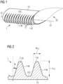
- FIG. 1 shows an embodiment of the inventive LEP 1 in relation to a wind turbine rotor blade 20 to which it will be mounted.
- the LEP 1 is mounted along the LE of the rotor blade 2, i.e. as a shield about the region in which the pressure side meets the suction side.
- the inventive LEP 1 comprises a curved body 10 that is shaped to lie on the rotor blade 2 on either side of the leading edge LE.
- a row of essentially identical fins 11 is shown. Each fin 11 protrudes from the curved body 10.
- Each fin 11 is essentially arc-shaped, and has a blunt outer face to which an outer reinforcement band 11R is mounted.
- the walls 11W or side faces of the fins 11 are steeply sloped, i.e.
- FIG. 1 shows a cross-section through the LEP 1, taken through a plane defined by the leading edge LE and its normal.
- Figure 2 shows a cross-section through the LEP 1, taken through a plane defined by the leading edge LE and its normal.
- This diagram also shows that the side walls 11W of a fin 11 subtend a steep angle ⁇ relative to the normal extending outward from the rotor blade surface.
- Figure 2 shows the LEP 1 in a partially assembled state, before outer reinforcement bands have been attached to the blunt or flat outer faces 11B of the fins 11, and before inner reinforcement bands have been attached to the valleys 10C between fins 11.
- Complete assemblies are shown in Figure 4 and Figure 5 , in which each fin 11 is topped with an outer reinforcement band 11R and each "valley" 10C is lined with an inner reinforcement band 10R.
- Figure 3 shows a wind turbine 2 with a number of rotor blades 20 mounted to a hub 21 that turns a component of a generator housed in a nacelle 22.
- the nacelle 22 is mounted on a tower 23, which can be located at an onshore or offshore site.
- the inventive LEP can be used along the entire leading edge LE of each rotor blade 20, or along a suitable fraction such as indicated here.
- suitable parameters such as fin spacing, fin width, fin height etc. may be identified with the help of simulations, wind tunnel testing techniques, etc. for that specific type of rotor blade 20.
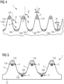
- Figure 4 shows exemplary shapes for the LEP reinforcement, showing a preferred convex shape of the outer reinforcement bands 11R and a preferred concave shape of the inner reinforcement bands 10R.
- the diagram also illustrates the beneficial effect of the inventive LEP 1, showing exemplary impacts by particles P such as hailstones or sand grains, relative to a normal to the surface at the point of impact. Any particle P that impinges on the steep side face 11W of a fin 11 will be deflected safely, thereby losing speed.
- the obtuse angle of impact ⁇ , ⁇ ' relative to the normal means that the force of impact is negligible, or at least so low as to not cause any significant damage.
- a particle P impinges on the LEP 1 at an acute angle of impact ⁇ , ⁇ ' relative to the normal.
- the vulnerable blunt faces 11B of the fins 11 and the vulnerable channels 10C between fins 11 are protected by reinforcing bands 11R, 10R which are constructed to absorb the force of impact to a large extent.
- FIG. 5 Exemplary embodiments of the reinforcing bands 11B, 11C are shown in more detail in Figure 5 .
- the drawing also shows a press-stud connection S between a reinforcing band 11R and a fin 11, and between a reinforcing band 10R and a channel 10C between fins 11.
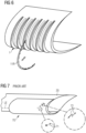
- the press-studs allow the reinforcing bands 11R, 10R to be mounted with relative ease, and also to be removed with little difficulty, as indicated in Figure 6 (for the sake of clarity, the openings for the press-studs are not shown) .
- Figure 7 shows a prior art LEP 70 for mounting over the leading edge LE of a rotor blade 20. While the prior art LEP 70 can prevent the rotor blade 20 from damage in the leading edge region, the protector 70 will be damaged by erosion or pitting, as shown in the enlarged image portions. These illustrate pitting 71 and gouging 72 as a result of highspeed impact from particles such as hailstones or sand.
Landscapes
- Engineering & Computer Science (AREA)
- Life Sciences & Earth Sciences (AREA)
- Sustainable Development (AREA)
- Sustainable Energy (AREA)
- Chemical & Material Sciences (AREA)
- Combustion & Propulsion (AREA)
- Mechanical Engineering (AREA)
- General Engineering & Computer Science (AREA)
- Physics & Mathematics (AREA)
- Fluid Mechanics (AREA)
- Wind Motors (AREA)
Claims (15)
- Dispositif de protection de bord d'attaque (1) pour une pale de rotor d'éolienne (2), comprenant- un corps incurvé (10) mis en forme pour une fixation à la pale de rotor (20) le long d'au moins une section de son bord d'attaque (LE) ;
et caractérisé par- une pluralité d'ailettes (11), chaque ailette (11) s'étendant radialement vers l'extérieur depuis le corps incurvé (10) et se terminant en une face externe contondante (11B), et dans lequel chaque ailette (11) comprend deux faces latérales (11W), chaque face latérale (11W) s'étendant depuis le corps incurvé (10) vers la face externe contondante (11B) ; et- une pluralité de bandes de renfort (11R), dans lequel une bande de renfort (11R) est fixée à la face externe contondante (11B) d'une ailette (11), et dans lequel une bande de renfort (11R) est mise en forme comme une continuation des faces latérales (11W) d'une ailette (11). - Dispositif de protection de bord d'attaque selon la revendication 1, dans lequel l'angle (Θ) sous-tendu par une face latérale (11W) à la normale comprend au plus 30°, plus préférablement au plus 20°, plus préférablement au plus 10°.
- Dispositif de protection de bord d'attaque selon la revendication 1 ou la revendication 2, dans lequel le ratio hauteur d'ailette (h11) à largeur moyenne d'ailette (w11) est d'au moins 3:1, plus préférablement d'au moins 4:1, plus préférablement d'au moins 5:1.
- Dispositif de protection de bord d'attaque selon l'une quelconque des revendications précédentes, dans lequel la section transversale d'une ailette (11) avec sa bande de renfort (11R) présente une forme parabolique globale.
- Dispositif de protection de bord d'attaque selon l'une quelconque des revendications précédentes, dans lequel une ailette (11) présente la forme d'un arc, et dans lequel la portée pointe-à-pointe de l'ailette (11) n'excède pas l'épaisseur maximale de la voilure de la pale de rotor à cette position.
- Dispositif de protection de bord d'attaque selon l'une quelconque des revendications précédentes, dans lequel une ailette (11) comprend des extrémités externes effilées.
- Dispositif de protection de bord d'attaque selon l'une quelconque des revendications précédentes, comprenant une pluralité de bandes de renfort internes (10R), dans lequel une bande de renfort interne (10R) est agencée entre deux ailettes (11) adjacentes et s'étend autour du corps incurvé (10).
- Dispositif de protection de bord d'attaque selon l'une quelconque des revendications précédentes, dans lequel les ailettes (11) et/ou le corps incurvé (10) sont constitué(es) d'un élastomère à base de polyuréthane.
- Dispositif de protection de bord d'attaque selon l'une quelconque des revendications précédentes, dans lequel les bandes de renfort (11R, 10R) sont constituées d'un plastique type polycarbonate.
- Éolienne (2) comprenant un nombre de pales de rotor (20), dans laquelle une pale de rotor (20) est équipée d'un dispositif de protection de bord d'attaque (1) selon l'une quelconque des revendications 1 à 9.
- Procédé de fabrication d'un dispositif de protection de bord d'attaque (1) selon l'une quelconque des revendications 1 à 9, lequel procédé comprend les étapes consistant à- mettre en forme un corps incurvé (10) pour une fixation à une pale de rotor (20) d'éolienne le long d'au moins une section de son bord d'attaque (LE) ;et lequel procédé est caractérisé par des étapes supplémentaires consistant à- mettre en forme une pluralité d'ailettes (11) pour s'étendre radialement vers l'extérieur depuis le corps incurvé (10), chaque ailette (11) se terminant en une face externe contondante (11B) et comprenant deux faces latérales (11W), chaque face latérale (11W) s'étendant depuis le corps incurvé (10) vers la face externe contondante (11B) ; et- fixer une pluralité de bandes de renfort (11R) externes aux faces externes contondantes (11B) des ailettes (11), dans lequel une bande de renfort (11R) est mise en forme comme une continuation des faces latérales (11W) d'une ailette (11).
- Procédé selon la revendication 11, comprenant une étape de fixation d'une pluralité de bandes de renfort internes (10R) au corps incurvé (10) entre les ailettes (11).
- Procédé selon la revendication 11 ou la revendication 12, comprenant une étape de mise en forme d'un nombre de renfoncements le long de la face contondante (11B) d'une ailette (11) et/ou le long du corps incurvé (10) entre des ailettes (11) adjacentes, dans lequel un renfoncement est formé pour recevoir une attache s'étendant depuis le dessous d'une bande de renfort (10R, 11R), et dans lequel l'étape de fixation d'une bande de renfort (10R, 11R) est effectuée en appliquant une pression pour pousser une attache dans un renfoncement correspondant pour former un raccord de type bouton-pression (S).
- Procédé selon la revendication 13, dans lequel une bande de renfort (10R, 11R) est construite pour permettre son détachement par traction pour libérer les attaches des renfoncements.
- Procédé selon l'une quelconque des revendications 11 à 14, dans lequel le corps incurvé (10) et les ailettes (11) sont moulés comme une seule pièce.
Priority Applications (5)
| Application Number | Priority Date | Filing Date | Title |
|---|---|---|---|
| PL20156881.3T PL3865703T3 (pl) | 2020-02-12 | 2020-02-12 | Osłona krawędzi natarcia łopatki wirnika turbiny wiatrowej |
| DK20156881.3T DK3865703T3 (en) | 2020-02-12 | 2020-02-12 | Wind turbine rotor blade leading-edge protector |
| EP20156881.3A EP3865703B1 (fr) | 2020-02-12 | 2020-02-12 | Protecteur de bord d'attaque de pale de rotor de turbine éolienne |
| US17/163,700 US11578694B2 (en) | 2020-02-12 | 2021-02-01 | Wind turbine rotor blade leading-edge protector |
| CN202110177148.2A CN113250899B (zh) | 2020-02-12 | 2021-02-09 | 风力涡轮机转子叶片前缘保护器 |
Applications Claiming Priority (1)
| Application Number | Priority Date | Filing Date | Title |
|---|---|---|---|
| EP20156881.3A EP3865703B1 (fr) | 2020-02-12 | 2020-02-12 | Protecteur de bord d'attaque de pale de rotor de turbine éolienne |
Publications (2)
| Publication Number | Publication Date |
|---|---|
| EP3865703A1 EP3865703A1 (fr) | 2021-08-18 |
| EP3865703B1 true EP3865703B1 (fr) | 2025-06-11 |
Family
ID=69581867
Family Applications (1)
| Application Number | Title | Priority Date | Filing Date |
|---|---|---|---|
| EP20156881.3A Active EP3865703B1 (fr) | 2020-02-12 | 2020-02-12 | Protecteur de bord d'attaque de pale de rotor de turbine éolienne |
Country Status (5)
| Country | Link |
|---|---|
| US (1) | US11578694B2 (fr) |
| EP (1) | EP3865703B1 (fr) |
| CN (1) | CN113250899B (fr) |
| DK (1) | DK3865703T3 (fr) |
| PL (1) | PL3865703T3 (fr) |
Families Citing this family (2)
| Publication number | Priority date | Publication date | Assignee | Title |
|---|---|---|---|---|
| EP3724486B1 (fr) * | 2017-12-12 | 2023-05-31 | LM Wind Power A/S | Dispositif de bord d'attaque de pale d'eolienne et procédé d'installation du dispositif de bord d'attaque |
| CN120476253A (zh) * | 2023-02-08 | 2025-08-12 | 保利泰克有限公司 | 用于生产具有倒角侧边缘的聚合物前缘保护片的方法 |
Family Cites Families (21)
| Publication number | Priority date | Publication date | Assignee | Title |
|---|---|---|---|---|
| CN101576060A (zh) * | 2008-05-07 | 2009-11-11 | 刘景斌 | 一种仿生式风力机 |
| EP2416950B1 (fr) * | 2009-04-10 | 2013-09-25 | XEMC Darwind B.V. | Pale protégée d'éolienne, procédé pour la fabriquer et éolienne |
| US8057189B2 (en) * | 2010-12-15 | 2011-11-15 | General Electric Company | Wind turbine blade with modular leading edge |
| EP2484901A2 (fr) * | 2011-02-04 | 2012-08-08 | Envision Energy (Denmark) ApS | Éolienne et procédé de commande associé |
| US9458821B2 (en) * | 2012-09-11 | 2016-10-04 | General Electric Company | Attachment system for a wind turbine rotor blade accessory |
| US9562513B2 (en) * | 2013-05-03 | 2017-02-07 | General Electric Company | Wind turbine rotor blade assembly with surface features |
| EP2811156A1 (fr) * | 2013-06-07 | 2014-12-10 | Siemens Aktiengesellschaft | Pale de rotor d'éolienne |
| DE102014106529B4 (de) * | 2014-05-09 | 2016-02-04 | Senvion Gmbh | Reparaturverfahren für Vortexgenerator und ein Bausatz dafür |
| BR112017009645B1 (pt) | 2014-11-10 | 2022-09-27 | Polytech A/S | Cobertura protetora pré-formada, lâmina de turbina eólica e seu método de produção |
| JP6421078B2 (ja) * | 2015-05-28 | 2018-11-07 | エムエイチアイ ヴェスタス オフショア ウィンド エー/エス | 風車翼及び風力発電装置、並びに風車翼の製造又は改造方法 |
| CN109790816A (zh) * | 2016-09-13 | 2019-05-21 | 波利科技股份有限公司 | 包括保护罩的风力涡轮机叶片 |
| WO2018060298A1 (fr) | 2016-09-27 | 2018-04-05 | Siemens Aktiengesellschaft | Système d'enveloppe protectrice adhésive |
| WO2018060297A1 (fr) | 2016-09-27 | 2018-04-05 | Siemens Aktiengesellschaft | Système de couverture pour protéger un bord d'attaque d'une pale de rotor d'éolienne |
| CN110036199A (zh) * | 2016-09-27 | 2019-07-19 | 西门子歌美飒可再生能源公司 | 保护罩系统 |
| JP2020507712A (ja) * | 2017-02-17 | 2020-03-12 | エムエイチアイ ヴェスタス オフショア ウィンド エー/エス | 風力タービンブレードの前縁部保護 |
| EP3724486B1 (fr) * | 2017-12-12 | 2023-05-31 | LM Wind Power A/S | Dispositif de bord d'attaque de pale d'eolienne et procédé d'installation du dispositif de bord d'attaque |
| ES2954182T3 (es) | 2018-03-08 | 2023-11-20 | Siemens Gamesa Renewable Energy As | Cubierta protectora para proteger un borde de ataque de una pala de turbina eólica |
| DK3567243T3 (da) * | 2018-05-11 | 2026-04-27 | Ge Vernova Renovables Espana S L | Vindmøllevingeforkantbeskyttelse |
| US11346320B2 (en) * | 2018-05-31 | 2022-05-31 | Vestas Wind Systems A/S | Wind turbine blade leading edge pairing |
| EP3578806A1 (fr) | 2018-06-04 | 2019-12-11 | Siemens Gamesa Renewable Energy A/S | Procédé de réparation d'un bord d'attaque d'une pale de turbine éolienne |
| EP3633186A1 (fr) | 2018-10-01 | 2020-04-08 | Siemens Gamesa Renewable Energy A/S | Feuille adhésive pour le montage d'une enveloppe protectrice sur une pale d'éolienne et procédé de montage d'une enveloppe protectrice sur une pale d'éolienne |
-
2020
- 2020-02-12 PL PL20156881.3T patent/PL3865703T3/pl unknown
- 2020-02-12 EP EP20156881.3A patent/EP3865703B1/fr active Active
- 2020-02-12 DK DK20156881.3T patent/DK3865703T3/da active
-
2021
- 2021-02-01 US US17/163,700 patent/US11578694B2/en active Active
- 2021-02-09 CN CN202110177148.2A patent/CN113250899B/zh active Active
Also Published As
| Publication number | Publication date |
|---|---|
| DK3865703T3 (en) | 2025-08-18 |
| PL3865703T3 (pl) | 2025-09-08 |
| US11578694B2 (en) | 2023-02-14 |
| CN113250899B (zh) | 2025-02-25 |
| US20210310459A1 (en) | 2021-10-07 |
| EP3865703A1 (fr) | 2021-08-18 |
| CN113250899A (zh) | 2021-08-13 |
Similar Documents
| Publication | Publication Date | Title |
|---|---|---|
| US8932024B2 (en) | Wind turbine blade and wind power generator using the same | |
| EP2514961B1 (fr) | Déflecteur pour pale de rotor d'éolienne | |
| EP3536947B1 (fr) | Couvercle de protection pour protéger un bord d'attaque d'une pale de turbine éolienne | |
| EP2713044B2 (fr) | Pale de rotor d'éolienne | |
| EP2927482A1 (fr) | Pale de turbine éolienne pourvue d'un écran de protection contre l'érosion | |
| CN110431303B (zh) | 前缘保护盖、风轮机叶片以及制备风轮机叶片的方法 | |
| EP3724486B1 (fr) | Dispositif de bord d'attaque de pale d'eolienne et procédé d'installation du dispositif de bord d'attaque | |
| CN108005730B (zh) | 涡轮发动机叶片前缘加强件 | |
| CN102996328A (zh) | 风机转子叶片的延伸件 | |
| US20120027588A1 (en) | Root flap for rotor blade in wind turbine | |
| US11578694B2 (en) | Wind turbine rotor blade leading-edge protector | |
| EP3655644A1 (fr) | Pale d'éolienne | |
| WO2018060299A1 (fr) | Système de couverture de protection | |
| US10907619B2 (en) | Lightning protection system for a rotor blade with a winglet | |
| US20190345912A1 (en) | Wind Turbine Blade Leading Edge Protection | |
| US20240068438A1 (en) | Protective cap for a leading edge of a wind turbine blade | |
| WO2018059768A1 (fr) | Agencement de pale de rotor d'éolienne | |
| EP2878806B1 (fr) | Procédé de fabrication d'une pale d'éolienne | |
| EP4027006B1 (fr) | Pale de rotor d'éolienne ayant deux rangées de générateurs de vortex | |
| WO2018059763A1 (fr) | Capuchon de protection pour protéger un bord d'attaque d'une pale de rotor d'éolienne | |
| CN114729619B (zh) | 风力涡轮机转子叶片导流装置及风力涡轮机转子叶片 | |
| CN215633503U (zh) | 叶片以及风力发电机组 | |
| EP3638898B1 (fr) | Protection de bord d'attaque pour pale d'éolienne | |
| JP2025044593A (ja) | 風車翼の保護層範囲決定方法及び風車翼 | |
| EP3551878A1 (fr) | Pale d'éolienne ayant un bord de fuite tronqué |
Legal Events
| Date | Code | Title | Description |
|---|---|---|---|
| PUAI | Public reference made under article 153(3) epc to a published international application that has entered the european phase |
Free format text: ORIGINAL CODE: 0009012 |
|
| STAA | Information on the status of an ep patent application or granted ep patent |
Free format text: STATUS: THE APPLICATION HAS BEEN PUBLISHED |
|
| AK | Designated contracting states |
Kind code of ref document: A1 Designated state(s): AL AT BE BG CH CY CZ DE DK EE ES FI FR GB GR HR HU IE IS IT LI LT LU LV MC MK MT NL NO PL PT RO RS SE SI SK SM TR |
|
| STAA | Information on the status of an ep patent application or granted ep patent |
Free format text: STATUS: REQUEST FOR EXAMINATION WAS MADE |
|
| 17P | Request for examination filed |
Effective date: 20220218 |
|
| RBV | Designated contracting states (corrected) |
Designated state(s): AL AT BE BG CH CY CZ DE DK EE ES FI FR GB GR HR HU IE IS IT LI LT LU LV MC MK MT NL NO PL PT RO RS SE SI SK SM TR |
|
| STAA | Information on the status of an ep patent application or granted ep patent |
Free format text: STATUS: EXAMINATION IS IN PROGRESS |
|
| 17Q | First examination report despatched |
Effective date: 20230405 |
|
| GRAP | Despatch of communication of intention to grant a patent |
Free format text: ORIGINAL CODE: EPIDOSNIGR1 |
|
| STAA | Information on the status of an ep patent application or granted ep patent |
Free format text: STATUS: GRANT OF PATENT IS INTENDED |
|
| INTG | Intention to grant announced |
Effective date: 20250114 |
|
| GRAS | Grant fee paid |
Free format text: ORIGINAL CODE: EPIDOSNIGR3 |
|
| GRAA | (expected) grant |
Free format text: ORIGINAL CODE: 0009210 |
|
| STAA | Information on the status of an ep patent application or granted ep patent |
Free format text: STATUS: THE PATENT HAS BEEN GRANTED |
|
| AK | Designated contracting states |
Kind code of ref document: B1 Designated state(s): AL AT BE BG CH CY CZ DE DK EE ES FI FR GB GR HR HU IE IS IT LI LT LU LV MC MK MT NL NO PL PT RO RS SE SI SK SM TR |
|
| REG | Reference to a national code |
Ref country code: GB Ref legal event code: FG4D |
|
| REG | Reference to a national code |
Ref country code: CH Ref legal event code: EP |
|
| REG | Reference to a national code |
Ref country code: DE Ref legal event code: R096 Ref document number: 602020052524 Country of ref document: DE |
|
| REG | Reference to a national code |
Ref country code: IE Ref legal event code: FG4D |
|
| REG | Reference to a national code |
Ref country code: DK Ref legal event code: T3 Effective date: 20250808 |
|
| REG | Reference to a national code |
Ref country code: NL Ref legal event code: FP |
|
| PG25 | Lapsed in a contracting state [announced via postgrant information from national office to epo] |
Ref country code: FI Free format text: LAPSE BECAUSE OF FAILURE TO SUBMIT A TRANSLATION OF THE DESCRIPTION OR TO PAY THE FEE WITHIN THE PRESCRIBED TIME-LIMIT Effective date: 20250611 Ref country code: ES Free format text: LAPSE BECAUSE OF FAILURE TO SUBMIT A TRANSLATION OF THE DESCRIPTION OR TO PAY THE FEE WITHIN THE PRESCRIBED TIME-LIMIT Effective date: 20250611 |
|
| REG | Reference to a national code |
Ref country code: LT Ref legal event code: MG9D |
|
| PG25 | Lapsed in a contracting state [announced via postgrant information from national office to epo] |
Ref country code: GR Free format text: LAPSE BECAUSE OF FAILURE TO SUBMIT A TRANSLATION OF THE DESCRIPTION OR TO PAY THE FEE WITHIN THE PRESCRIBED TIME-LIMIT Effective date: 20250912 Ref country code: NO Free format text: LAPSE BECAUSE OF FAILURE TO SUBMIT A TRANSLATION OF THE DESCRIPTION OR TO PAY THE FEE WITHIN THE PRESCRIBED TIME-LIMIT Effective date: 20250911 |
|
| PG25 | Lapsed in a contracting state [announced via postgrant information from national office to epo] |
Ref country code: BG Free format text: LAPSE BECAUSE OF FAILURE TO SUBMIT A TRANSLATION OF THE DESCRIPTION OR TO PAY THE FEE WITHIN THE PRESCRIBED TIME-LIMIT Effective date: 20250611 |
|
| PG25 | Lapsed in a contracting state [announced via postgrant information from national office to epo] |
Ref country code: HR Free format text: LAPSE BECAUSE OF FAILURE TO SUBMIT A TRANSLATION OF THE DESCRIPTION OR TO PAY THE FEE WITHIN THE PRESCRIBED TIME-LIMIT Effective date: 20250611 |
|
| PG25 | Lapsed in a contracting state [announced via postgrant information from national office to epo] |
Ref country code: RS Free format text: LAPSE BECAUSE OF FAILURE TO SUBMIT A TRANSLATION OF THE DESCRIPTION OR TO PAY THE FEE WITHIN THE PRESCRIBED TIME-LIMIT Effective date: 20250911 |
|
| PG25 | Lapsed in a contracting state [announced via postgrant information from national office to epo] |
Ref country code: LV Free format text: LAPSE BECAUSE OF FAILURE TO SUBMIT A TRANSLATION OF THE DESCRIPTION OR TO PAY THE FEE WITHIN THE PRESCRIBED TIME-LIMIT Effective date: 20250611 |
|
| PG25 | Lapsed in a contracting state [announced via postgrant information from national office to epo] |
Ref country code: PT Free format text: LAPSE BECAUSE OF FAILURE TO SUBMIT A TRANSLATION OF THE DESCRIPTION OR TO PAY THE FEE WITHIN THE PRESCRIBED TIME-LIMIT Effective date: 20251013 |
|
| REG | Reference to a national code |
Ref country code: AT Ref legal event code: MK05 Ref document number: 1802445 Country of ref document: AT Kind code of ref document: T Effective date: 20250611 |
|
| PG25 | Lapsed in a contracting state [announced via postgrant information from national office to epo] |
Ref country code: IS Free format text: LAPSE BECAUSE OF FAILURE TO SUBMIT A TRANSLATION OF THE DESCRIPTION OR TO PAY THE FEE WITHIN THE PRESCRIBED TIME-LIMIT Effective date: 20251011 |
|
| PG25 | Lapsed in a contracting state [announced via postgrant information from national office to epo] |
Ref country code: AT Free format text: LAPSE BECAUSE OF FAILURE TO SUBMIT A TRANSLATION OF THE DESCRIPTION OR TO PAY THE FEE WITHIN THE PRESCRIBED TIME-LIMIT Effective date: 20250611 Ref country code: SM Free format text: LAPSE BECAUSE OF FAILURE TO SUBMIT A TRANSLATION OF THE DESCRIPTION OR TO PAY THE FEE WITHIN THE PRESCRIBED TIME-LIMIT Effective date: 20250611 |
|
| PG25 | Lapsed in a contracting state [announced via postgrant information from national office to epo] |
Ref country code: CZ Free format text: LAPSE BECAUSE OF FAILURE TO SUBMIT A TRANSLATION OF THE DESCRIPTION OR TO PAY THE FEE WITHIN THE PRESCRIBED TIME-LIMIT Effective date: 20250611 |
|
| PG25 | Lapsed in a contracting state [announced via postgrant information from national office to epo] |
Ref country code: EE Free format text: LAPSE BECAUSE OF FAILURE TO SUBMIT A TRANSLATION OF THE DESCRIPTION OR TO PAY THE FEE WITHIN THE PRESCRIBED TIME-LIMIT Effective date: 20250611 |
|
| PG25 | Lapsed in a contracting state [announced via postgrant information from national office to epo] |
Ref country code: RO Free format text: LAPSE BECAUSE OF FAILURE TO SUBMIT A TRANSLATION OF THE DESCRIPTION OR TO PAY THE FEE WITHIN THE PRESCRIBED TIME-LIMIT Effective date: 20250611 Ref country code: SK Free format text: LAPSE BECAUSE OF FAILURE TO SUBMIT A TRANSLATION OF THE DESCRIPTION OR TO PAY THE FEE WITHIN THE PRESCRIBED TIME-LIMIT Effective date: 20250611 |
|
| REG | Reference to a national code |
Ref country code: DE Ref legal event code: R097 Ref document number: 602020052524 Country of ref document: DE |
|
| PGFP | Annual fee paid to national office [announced via postgrant information from national office to epo] |
Ref country code: NL Payment date: 20260220 Year of fee payment: 7 |
|
| PGFP | Annual fee paid to national office [announced via postgrant information from national office to epo] |
Ref country code: GB Payment date: 20260223 Year of fee payment: 7 |
|
| PGFP | Annual fee paid to national office [announced via postgrant information from national office to epo] |
Ref country code: DE Payment date: 20250829 Year of fee payment: 7 Ref country code: DK Payment date: 20260223 Year of fee payment: 7 |
|
| PG25 | Lapsed in a contracting state [announced via postgrant information from national office to epo] |
Ref country code: IT Free format text: LAPSE BECAUSE OF FAILURE TO SUBMIT A TRANSLATION OF THE DESCRIPTION OR TO PAY THE FEE WITHIN THE PRESCRIBED TIME-LIMIT Effective date: 20250611 |
|
| PLBE | No opposition filed within time limit |
Free format text: ORIGINAL CODE: 0009261 |
|
| STAA | Information on the status of an ep patent application or granted ep patent |
Free format text: STATUS: NO OPPOSITION FILED WITHIN TIME LIMIT |
|
| PGFP | Annual fee paid to national office [announced via postgrant information from national office to epo] |
Ref country code: FR Payment date: 20260227 Year of fee payment: 7 |
|
| REG | Reference to a national code |
Ref country code: CH Ref legal event code: L10 Free format text: ST27 STATUS EVENT CODE: U-0-0-L10-L00 (AS PROVIDED BY THE NATIONAL OFFICE) Effective date: 20260423 |
|
| PGFP | Annual fee paid to national office [announced via postgrant information from national office to epo] |
Ref country code: PL Payment date: 20260115 Year of fee payment: 7 |