EP3865708B1 - Nicht-pulsierende pumpe - Google Patents
Nicht-pulsierende pumpe Download PDFInfo
- Publication number
- EP3865708B1 EP3865708B1 EP21167793.5A EP21167793A EP3865708B1 EP 3865708 B1 EP3865708 B1 EP 3865708B1 EP 21167793 A EP21167793 A EP 21167793A EP 3865708 B1 EP3865708 B1 EP 3865708B1
- Authority
- EP
- European Patent Office
- Prior art keywords
- inner pressure
- pump
- pressure
- reciprocating
- chamber
- Prior art date
- Legal status (The legal status is an assumption and is not a legal conclusion. Google has not performed a legal analysis and makes no representation as to the accuracy of the status listed.)
- Active
Links
Images










Classifications
-
- F—MECHANICAL ENGINEERING; LIGHTING; HEATING; WEAPONS; BLASTING
- F04—POSITIVE - DISPLACEMENT MACHINES FOR LIQUIDS; PUMPS FOR LIQUIDS OR ELASTIC FLUIDS
- F04B—POSITIVE-DISPLACEMENT MACHINES FOR LIQUIDS; PUMPS
- F04B43/00—Machines, pumps, or pumping installations having flexible working members
- F04B43/02—Machines, pumps, or pumping installations having flexible working members having plate-like flexible members, e.g. diaphragms
- F04B43/025—Machines, pumps, or pumping installations having flexible working members having plate-like flexible members, e.g. diaphragms two or more plate-like pumping members in parallel
- F04B43/026—Machines, pumps, or pumping installations having flexible working members having plate-like flexible members, e.g. diaphragms two or more plate-like pumping members in parallel each plate-like pumping flexible member working in its own pumping chamber
-
- F—MECHANICAL ENGINEERING; LIGHTING; HEATING; WEAPONS; BLASTING
- F04—POSITIVE - DISPLACEMENT MACHINES FOR LIQUIDS; PUMPS FOR LIQUIDS OR ELASTIC FLUIDS
- F04B—POSITIVE-DISPLACEMENT MACHINES FOR LIQUIDS; PUMPS
- F04B11/00—Equalisation of pulses, e.g. by use of air vessels; Counteracting cavitation
- F04B11/005—Equalisation of pulses, e.g. by use of air vessels; Counteracting cavitation using two or more pumping pistons
-
- F—MECHANICAL ENGINEERING; LIGHTING; HEATING; WEAPONS; BLASTING
- F04—POSITIVE - DISPLACEMENT MACHINES FOR LIQUIDS; PUMPS FOR LIQUIDS OR ELASTIC FLUIDS
- F04B—POSITIVE-DISPLACEMENT MACHINES FOR LIQUIDS; PUMPS
- F04B13/00—Pumps specially modified to deliver fixed or variable measured quantities
-
- F—MECHANICAL ENGINEERING; LIGHTING; HEATING; WEAPONS; BLASTING
- F04—POSITIVE - DISPLACEMENT MACHINES FOR LIQUIDS; PUMPS FOR LIQUIDS OR ELASTIC FLUIDS
- F04B—POSITIVE-DISPLACEMENT MACHINES FOR LIQUIDS; PUMPS
- F04B43/00—Machines, pumps, or pumping installations having flexible working members
- F04B43/02—Machines, pumps, or pumping installations having flexible working members having plate-like flexible members, e.g. diaphragms
- F04B43/06—Pumps having fluid drive
- F04B43/067—Pumps having fluid drive the fluid being actuated directly by a piston
-
- F—MECHANICAL ENGINEERING; LIGHTING; HEATING; WEAPONS; BLASTING
- F04—POSITIVE - DISPLACEMENT MACHINES FOR LIQUIDS; PUMPS FOR LIQUIDS OR ELASTIC FLUIDS
- F04B—POSITIVE-DISPLACEMENT MACHINES FOR LIQUIDS; PUMPS
- F04B49/00—Control, e.g. of pump delivery, or pump pressure of, or safety measures for, machines, pumps, or pumping installations, not otherwise provided for, or of interest apart from, groups F04B1/00 - F04B47/00
- F04B49/12—Control, e.g. of pump delivery, or pump pressure of, or safety measures for, machines, pumps, or pumping installations, not otherwise provided for, or of interest apart from, groups F04B1/00 - F04B47/00 by varying the length of stroke of the working members
-
- F—MECHANICAL ENGINEERING; LIGHTING; HEATING; WEAPONS; BLASTING
- F04—POSITIVE - DISPLACEMENT MACHINES FOR LIQUIDS; PUMPS FOR LIQUIDS OR ELASTIC FLUIDS
- F04B—POSITIVE-DISPLACEMENT MACHINES FOR LIQUIDS; PUMPS
- F04B9/00—Piston machines or pumps characterised by the driving or driven means to or from their working members
- F04B9/02—Piston machines or pumps characterised by the driving or driven means to or from their working members the means being mechanical
- F04B9/04—Piston machines or pumps characterised by the driving or driven means to or from their working members the means being mechanical the means being cams, eccentrics or pin-and-slot mechanisms
- F04B9/042—Piston machines or pumps characterised by the driving or driven means to or from their working members the means being mechanical the means being cams, eccentrics or pin-and-slot mechanisms the means being cams
-
- F—MECHANICAL ENGINEERING; LIGHTING; HEATING; WEAPONS; BLASTING
- F04—POSITIVE - DISPLACEMENT MACHINES FOR LIQUIDS; PUMPS FOR LIQUIDS OR ELASTIC FLUIDS
- F04B—POSITIVE-DISPLACEMENT MACHINES FOR LIQUIDS; PUMPS
- F04B2201/00—Pump parameters
- F04B2201/02—Piston parameters
- F04B2201/0206—Length of piston stroke
-
- F—MECHANICAL ENGINEERING; LIGHTING; HEATING; WEAPONS; BLASTING
- F04—POSITIVE - DISPLACEMENT MACHINES FOR LIQUIDS; PUMPS FOR LIQUIDS OR ELASTIC FLUIDS
- F04B—POSITIVE-DISPLACEMENT MACHINES FOR LIQUIDS; PUMPS
- F04B2203/00—Motor parameters
- F04B2203/09—Motor parameters of linear hydraulic motors
- F04B2203/0903—Position of the driving piston
-
- F—MECHANICAL ENGINEERING; LIGHTING; HEATING; WEAPONS; BLASTING
- F04—POSITIVE - DISPLACEMENT MACHINES FOR LIQUIDS; PUMPS FOR LIQUIDS OR ELASTIC FLUIDS
- F04B—POSITIVE-DISPLACEMENT MACHINES FOR LIQUIDS; PUMPS
- F04B9/00—Piston machines or pumps characterised by the driving or driven means to or from their working members
- F04B9/02—Piston machines or pumps characterised by the driving or driven means to or from their working members the means being mechanical
Definitions
- the present disclosure relates to a reciprocating pump, and in particular to a structure of a non-pulsating pump which is controlled such that a flow rate of discharge is constant.
- non-pulsating pumps which comprise two reciprocating pumps (duplex system) or three reciprocating pumps (triplex system).
- a non-pulsating pump comprises, for example, a common intake line and a common discharge line which are connected to each of the reciprocating pumps.
- a reciprocating pump comprises a plunger which reciprocates, a pump chamber having a volume that is increased and decreased with forward and backward movements (reciprocating motion) of the plunger, and an intake valve and a discharge valve which are connected to the pump chamber.
- a pressure of the pump chamber is decreased, the intake valve is opened in response thereto, and liquid is introduced into the pump chamber.
- the plunger moves past a bottom dead center and moves forward (forward motion)
- the pressure of the pump chamber is increased, and the discharge valve is opened. Liquid is sent through the opened discharge valve to the common discharge line.
- a driving device of each reciprocating pump As a driving device of each reciprocating pump, a motor, a cam shaft, and an eccentric drive cam are provided.
- the plunger of the reciprocating pump is connected to the eccentric drive cam, and the plunger is moved forward and backward according to rotation of the cam.
- a sum of a flow rate Q1 of discharge from the one reciprocating pump and a flow rate Q2 of discharge from the other reciprocating pump is a line flow rate Q_L.
- a constant line flow rate Q_L1 can be obtained.
- a compression step is provided in which an inner pressure of the reciprocating pump is increased.
- the inside of the pump chamber is compressed until an inner pressure P_OR1 of the pump chamber of the reciprocating pump is equal to the line pressure P_L at the discharging side.
- the discharge valve separating the pump chamber and the common discharge line is set to an open state.
- a pressure sensor or a flow rate sensor is provided on the common line, and an air release valve in communication with the pump chamber is also provided on the common line.
- the pressure of the pump chamber is adjusted by the air release valve, so as to reduce the pulsation.
- Document JP 3 861 060 B2 discloses preventing a decrease in a delivery quantity in an initial stage of a delivery period of a diaphragm pump by decreasing a volume of a pump chamber by driving a plunger in a delivery direction just before the period.
- This decrease of pump chamber volume is set to be larger than decreased delivery quantity, and operating fluid equivalent to difference between them is discharged by a discharge mechanism.
- a pulsation sensor is provided on a duct on the delivery side, and a control part detects pulsation based on a signal from the sensor. The control part regulates the discharge quantity of the discharge mechanism to offset the pulsation.
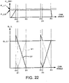
- a pulsation waveform does not take a shape as shown in FIG. 22 .
- the pulsation has a sharp spike shape starting at the cam angles of ⁇ 0 and ⁇ 3 where the process switches from the intake step to the discharge step, but in reality, depending on a placement of the sensor, viscosity of the liquid, expansion of the line, or the like, the pulsation waveform has a gradual curved line shape rising from cam angles ⁇ 0 and ⁇ 3 and having peaks at cam angles of ⁇ 1 and ⁇ 4, as exemplified in FIG. 23 . In this manner, the actually detected pulsation waveform has a low difference value (differentiation value) in comparison to the spike shape, and, as a consequence, pulsation detection precision may be reduced and pulsation suppression may become difficult.
- An advantage of the present disclosure lies in provision of a non-pulsating pump which can suppress the pulsation with a higher precision than in the related art.
- a non-pulsating pump comprises a drive mechanism, a plurality of reciprocating pumps, and a stroke adjustment mechanism.
- the drive mechanism comprises a cam mechanism and a plurality of crossheads.
- the cam mechanism converts a rotational motion of a drive motor into a reciprocating motion.
- the plurality of crossheads are reciprocated by the cam mechanism with a predetermined phase difference.
- Each of the plurality of reciprocating pumps comprises a plunger, a pump chamber, an intake valve, and a discharge valve.
- the plunger is connected to the crosshead, and reciprocates with the reciprocating motion of the crosshead.
- the pump chamber has an inner pressure which changes with the reciprocating motion of the plunger.
- the intake valve connects a common intake line and the pump chamber, and has a side of the pump chamber as a back pressure side.
- the discharge valve connects the pump chamber and a common discharge line, and has a side of the common discharge line as a back pressure side.
- the stroke adjustment mechanism adjusts an effective stroke length for the crosshead to reciprocate the plunger.
- the stroke adjustment mechanism adjusts the effective stroke length of the crosshead connected to the plunger of the predetermined reciprocating pump based on the pressure difference such that the inner pressure of the pump chamber reaches the line pressure at the discharge step starting point angle.
- the stroke adjustment mechanism may connect the plunger to the crosshead so as to enable a free reciprocating motion along a reciprocating motion direction of the crosshead.
- the effective stroke length of the crosshead is adjusted by adjusting a range of the free reciprocating motion.
- the stroke adjustment mechanism may comprise a stopper which determines a range of the free reciprocating motion of the plunger, and an adjustment motor which moves the stopper forward and backward in the reciprocating motion direction of the crosshead.
- a forward/backward movement range of the stopper by the adjustment motor is determined based on a difference between the inner pressure of the pump chamber of the predetermined reciprocating pump at the discharge step starting point angle and the line pressure at the single discharge step.
- a non-pulsating pump comprises a drive mechanism and a plurality of reciprocating pumps.
- the drive mechanism comprises a cam mechanism and a plurality of crossheads.
- the cam mechanism converts a rotational motion of a drive motor into a reciprocating motion.
- the plurality of crossheads are reciprocated by the cam mechanism with a predetermined phase difference.
- Each of the plurality of reciprocating pumps comprises a plunger, a pump chamber, an intake valve, a discharge valve, and an inner pressure adjustment mechanism.
- the plunger is connected to the crosshead, and reciprocates with the reciprocating motion of the crosshead.
- the pump chamber has an inner pressure which changes with the reciprocating motion of the plunger.
- the intake valve connects a common intake line and the pump chamber, and has a side of the pump chamber as a back pressure side.
- the discharge valve connects the pump chamber and a common discharge line, and has a side of the common discharge line as a back pressure side.
- the inner pressure adjustment mechanism can adjust the inner pressure of the pump chamber.
- the inner pressure adjustment mechanism adjusts the inner pressure of the pump chamber of the predetermined reciprocating pump based on the pressure difference such that the inner pressure of the pump chamber reaches the line pressure at the discharge step starting point angle.
- the non-pulsating pump comprises a drive mechanism, a plurality of reciprocating pumps, and a stroke adjustment mechanism.
- the drive mechanism comprises a cam mechanism and crossheads.
- the cam mechanism converts a rotational motion of a drive motor into a reciprocating motion.
- a plurality of crossheads are reciprocated by the cam mechanism with a predetermined phase difference.
- Each of the plurality of reciprocating pumps comprises a plunger, a pump chamber, an intake valve, and a discharge valve.
- the plunger is connected to the crosshead, and reciprocates with the reciprocating motion of the crosshead.
- the pump chamber has an inner pressure which changes with the reciprocating motion of the plunger.
- the intake valve connects a common intake line and the pump chamber, and has a side of the pump chamber as a back pressure side.
- the discharge valve connects the pump chamber and a common discharge line, and has a side of the common discharge line as a back pressure side.
- the stroke adjustment mechanism adjusts an effective stroke length for the crosshead to reciprocate the plunger.
- the effective stroke length of the crosshead connected to the plunger of the predetermined reciprocating pump is adjusted based on the pressure difference such that the inner pressure of the pump chamber reaches the line pressure at the discharge step starting point angle.
- the non-pulsating pump comprises a drive mechanism and a plurality of reciprocating pumps.
- the drive mechanism comprises a cam mechanism and a plurality of crossheads.
- the cam mechanism converts a rotational motion of a drive motor into a reciprocating motion.
- the plurality of crossheads are reciprocated by the cam mechanism with a predetermined phase difference.
- Each of the plurality of reciprocating pumps comprises a plunger, a pump chamber, an intake valve, a discharge valve, and an inner pressure adjustment mechanism.
- the plunger is connected to the crosshead and reciprocates with the reciprocating motion of the crosshead.
- the pump chamber has an inner pressure which changes with the reciprocating motion of the plunger.
- the intake valve connects a common intake line and the pump chamber, and has a side of the pump chamber as a back pressure side.
- the discharge valve connects the pump chamber and a common discharge line, and has a side of the common discharge line as a back pressure side.
- the inner pressure adjustment mechanism can adjust the inner pressure of the pump chamber.
- the inner pressure of the pump chamber of the predetermined reciprocating pump is adjusted based on the pressure difference such that the inner pressure of the pump chamber reaches the line pressure at the discharge step starting point angle.
- a non-pulsating pump can be provided in which pulsation can be suppressed with a higher precision than in the related art.
- a non-pulsating pump 100 according to an example useful for understanding the claimed invention will now be described with reference to the drawings.
- a direction of reciprocating motions of crossheads 28 and 48 is set as an X axis.
- a pressurizing direction of pump chambers 220 and 240 is set as a positive direction.
- a Y axis and a Z axis are defined to be perpendicular to the X axis.
- An X-Y plane is a horizontal plane.
- the Z axis is a vertical axis.
- the non-pulsating pump 100 of the present example is used in a process that requires supply of a fluid continuously and at a constant flow rate.
- supply of fluid with a high pressure is enabled, and, for example, the fluid can be supplied with a pressure of about 40 MPa.
- the non-pulsating pump of the present embodiment is used for a mixing process of medicines or paints.
- the non-pulsating pump 100 comprises a drive mechanism 250, a plurality of reciprocating pumps 20 and 40, a stroke adjustment mechanism 80, and a control unit 160.
- the drive mechanism 250 drives the plurality of reciprocating pumps 20 and 40.
- the drive mechanism 250 comprises a frame 10, a drive motor 11, a shaft 12, a rotary encoder 130, a cam mechanism 16, and crossheads 28 and 48.
- the frame 10 supports a driving element in the drive mechanism 250.
- the frame 10 is made from a metal material, and has a hollow structure.
- the cam mechanism 16 and the stroke adjustment mechanisms 80 and 80 are housed in the frame 10.
- the frame 10 is supported on a fixing element such as a base.
- the drive motor 11 rotationally drives the shaft 12.
- the drive motor 11 may be any motor which can rotate with uniform velocity, and is formed from, for example, an inverter motor. A rotational drive force of the drive motor 11 is transmitted to the shaft 12 having a small size and a shaft 13 having a large size and provided beyond the shaft 12.
- the rotary encoder 130 detects a rotational phase of the drive motor 11.
- the rotary encoder 130 includes a slit disk 131, a light emitting element 132, and a light receiving element 133.
- the slit disk 131 is engaged with the shaft 12, and is rotated along with the shaft 12.
- a plurality of slits are formed to penetrate through in an axial direction, radially from a center of rotation of the shaft 12.
- one of the plurality of slits may be formed in a different shape from the other slits. For example, one slit having a wider width in a circumferential direction in comparison to other slits may be formed in the slit disk 131.
- the light emitting element 132 and the light receiving element 133 are provided with the slit of the slit disk 131 therebetween in the axial direction.
- the light receiving element 133 detects blocking/passing of light illuminated from the light emitting element 132 by the slit disk 131, and transmits a detection signal thereof to the control unit 160.
- the control unit 160 receives the detection signal from the light receiving element 133, and determines a rotational phase of the rotation cam 15, that is, a cam angle ⁇ .
- a protrusion may be provided along the circumference on a disk surface, and may be detected by a proximity sensor.
- the cam mechanism 16 converts a rotational motion of the drive motor 11 into a reciprocating motion.
- the cam mechanism 16 comprises the shaft 13, the rotation cam 15, and rollers 29 and 49.
- the rotation cam 15 is engaged with the shaft 13, and is rotated along with the shaft 13.
- the rotation cam 15 is formed in an approximately circular disk shape.
- the rotation cam 15 is engaged with the shaft 13 with a circular disk surface thereof being non-perpendicular, that is, inclined with respect to, the axial direction of the shaft 13.
- the shaft 13 and the rotation cam 15 may be integrally cut out.
- the crossheads 28 and 48 connected to the rotation cam 15 are moved forward and backward according to the rotational phase of the rotation cam 15.
- the shape of the rotation cam 15 is determined such that the forward and backward displacements of the crossheads 28 and 48, that is, strokes X_XH1 and X_XH2, have waveforms (profiles) as shown in FIG. 7 .
- the rollers 29 and 49 are configured such that rotational shafts thereof (shown by broken lines) are respectively inserted into the crossheads 28 and 48, orthogonal to the forward/backward movement directions of the crossheads 28 and 48.
- a pair of the rollers 29 and 49 are provided along the forward/backward movement directions of the crossheads 28 and 48, respectively, and a peripheral portion of the rotation cam 15 is sandwiched therebetween.
- the crossheads 28 and 48 are reciprocated by the cam mechanism 16.
- the crossheads 28 and 48 have, for example, a circular column shape extending in the forward/backward movement direction, and holes with bottoms 28a (refer to FIG. 3 ) are formed at front ends thereof (ends in the direction of movement).
- the crossheads 28 and 48 are reciprocated by the cam mechanism 16 with a predetermined phase difference.
- a pair of crossheads 28 and 48 are provided, and are connected to the rotation cam 15 with a phase difference of 180°.
- the crossheads 28 and 48 are placed on a same plane as the shaft 13, with the shaft 13 therebetween.
- the reciprocating pumps 20 and 40 are driven by the drive mechanism 250.
- the reciprocating pumps 20 and 40 comprise pump chambers 220 and 240, plungers 26 and 46, intake valves 31 and 51, and discharge valves 33 and 53, respectively.
- the plungers 26 and 46 are connected to the crossheads 28 and 48 via the stroke adjustment mechanisms 80 and 80, respectively.
- the plungers 26 and 46 reciprocate with the reciprocating motions of the crossheads 28 and 48, respectively.
- the drive forces are transmitted by the stroke adjustment mechanism 80 and 80 provided between the plungers 26 and 46 and the crossheads 28 and 48, respectively, to the plungers 26 and 46 in a state with "play" with respect to the reciprocating motions of the crossheads 28 and 48, respectively.
- the pump chambers 220 and 240 have hydraulic chambers 22 and 42 and fluid chambers 25 and 45, respectively.
- the hydraulic chambers 22 and 42 and the fluid chambers 25 and 45 are respectively separated by flexible diaphragms 23 and 43.
- the hydraulic chambers 22 and 42 are surrounded by casings of the pump chambers 220 and 240, the diaphragms 23 and 43, and packings 27 and 47, respectively, and oil of a predetermined viscosity is sealed.
- Front portions of the plungers 26 and 46 are inserted into the hydraulic chambers 22 and 42, respectively, in a manner to be sandwiched by the packings 27 and 47.
- the inner pressures of the hydraulic chambers 22 and 42 and the fluid chambers 25 and 45 change with the forward and backward movements of the plungers 26 and 46, respectively.
- Fluid supplied to a common intake line 35 and to a common discharge line 36 is introduced to or discharged from the fluid chambers 25 and 45.
- the non-pulsating pump 100 of the present embodiment is used for a mixing process of medicines or paints
- liquids which are materials of the medicine or the paint are introduced into or discharged from the fluid chambers 25 and 45.
- the fluid chambers 25 and 45 are formed from, for example, a corrosion-resistant member.
- Intake lines 30 and 50 branched from the common intake line 35 are connected to (in communication with) the fluid chambers 25 and 45 via the intake valves 31 and 51, respectively.
- discharge lines 32 and 52 merging to the common discharge line 36 are connected to (in communication with) the fluid chambers 25 and 45 via the discharge valves 33 and 53, respectively.
- the inner pressures of the hydraulic chambers 22 and 42 change with the forward/backward movements of the plungers 26 and 46, respectively.
- the inner pressures of the fluid chambers 25 and 45, separated from the hydraulic chambers 22 and 42 by the flexible diaphragms 23 and 43, respectively, change following the changes of the inner pressures of the hydraulic chambers 22 and 42, respectively. More specifically, the inner pressures of the hydraulic chambers 22 and 42 are respectively equal to the inner pressures of the fluid chambers 25 and 45.
- the intake valves 31 and 51 are valves connecting the common intake line 35 and the fluid chambers 25 and 45 of the pump chambers 220 and 240, respectively.
- the intake valves 31 and 51 have the sides of the fluid chambers 25 and 45 of the pump chambers 220 and 240, respectively, as a back pressure side. That is, when the inner pressures of the fluid chambers 25 and 45 respectively exceed the pressure of the common intake line 35, the intake valves 31 and 51 are respectively closed. In addition, when the inner pressures of the fluid chambers 25 and 45 respectively become less than or equal to the pressure of the common intake line 35, the intake valves 31 and 51 are respectively opened, and the fluid (liquid) of the common intake line 35 flows into the fluid chambers 25 and 45, respectively.
- an urging member such as a spring does not need to be provided on a valve member of the intake valves 31 and 51.
- the discharge valves 33 and 53 are valves respectively connecting the common discharge line 36 and the fluid chambers 25 and 45 of the pump chambers 220 and 240.
- the discharge valves 33 and 53 have the sides at the common discharge line 36 as a back pressure side. That is, when the pressure of the common discharge line 36 exceeds the inner pressures of the fluid chambers 25 and 45, respectively, the discharge valves 33 and 53 are respectively closed. In addition, when the inner pressures of the fluid chambers 25 and 45 respectively become higher than or equal to the pressure of the common discharge line 36, the discharge valves 33 and 53 are respectively opened, and the fluid in the fluid chambers 25 and 45 is respectively sent to the common discharge line 36.
- an urging member such as a spring does not need to be provided on a valve member of the discharge valves 33 and 53.
- inner pressure sensors 64 and 65 for detecting the inner pressures thereof are respectively provided.
- the inner pressure sensors 64 and 65 are connected to, for example, the hydraulic chambers 22 and 42, respectively. Because the inner pressures P_OR1 and P OR2 of the hydraulic chambers 22 and 42 are respectively equal to the inner pressures of the fluid chambers 25 and 45, as described above, pressure values detected by the inner pressure sensors 64 and 65 may be considered to be the inner pressures of the fluid chambers 25 and 45, respectively.
- the inner pressures P_OR1 and P_OR2 of the hydraulic chambers 22 and 42 detected by the inner pressure sensors 64 and 65, respectively, are transmitted to the control unit 160.
- a line pressure sensor 63 is provided on the common discharge line 36.
- the line pressure sensor 63 detects a pressure (pipe pressure, line pressure) P_L of the common discharge line.
- a corrosion-resistant pressure sensor is used as the line pressure sensor 63.
- the inner pressure sensors 64 and 65 may be used to detect the line pressure P_L.
- the inner pressure sensors 64 and 65 may be used to detect the line pressure P_L.
- the stroke adjustment mechanisms 80 are provided between rear ends (ends on the sides spaced away from the pump chambers 220 and 240) of the plungers 26 and 46 and front ends of the crossheads 28 and 48, respectively.
- the stroke adjustment mechanisms 80 adjust effective stroke lengths of the reciprocating motions of the plungers 26 and 46 by the crossheads 28 and 48.
- the stroke adjustment mechanisms 80 comprise bodies 81, stoppers 82, reinforcement members 83, coil springs 84, support rings 85, bolts 86 and 87, worm gears 121 and 141, worm wheels 122 and 142, and adjustment motors 120 and 140, respectively.
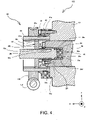
- FIGs. 3 and 5 exemplify side cross sectional diagrams of the stroke adjustment mechanism 80 on the side of the reciprocating pump 20.
- the stroke adjustment mechanism 80 on the side of the reciprocating pump 40 has a similar structure. More specifically, in the following description, the number "2" in the tens digit position may be replaced with "4" in the reference numerals of the constituting elements, to describe the structure of the stroke adjustment mechanism 80 on the side of the reciprocating pump 40.
- the hole with the bottom 28a is formed at a front end of the crosshead 28, formed in the axial direction.
- a rear end portion 26f of the plunger 26 is inserted into this hole with the bottom 28a.
- the reinforcement member 83 is provided on a bottom surface 28b of the hole with the bottom 28a.
- a front end surface 83a of the reinforcement member 83 and a rear end surface 26d of the plunger 26 oppose each other along the forward/backward movement direction of the plunger 26.
- a diameter of the reinforcement member 83 is formed to be smaller than an inner size of the hole with the bottom 28a, and the coil spring 84 which is an urging member is provided at an outer circumference of the reinforcement member 83.
- a rear end of the coil spring 84 abuts the bottom surface 28b of the hole with the bottom 28a, and a front end of the coil spring 84 abuts a rear surface 26c of an enlarged-diameter portion 26a of the plunger 26.
- the enlarged-diameter portion 26a having a larger diameter than the rear end portion 26f is provided.
- the front end of the coil spring 84 is fitted to the rear end portion 26f, and abuts the rear surface 26c of the enlarged-diameter portion 26a.
- a front surface 26b of the enlarged-diameter portion 26a abuts a rear surface 82e of the stopper 82.
- the stopper 82 is a member having an approximately circular tubular shape, and comprises a circular ring portion 82a and an arm 82b in front of the circular ring portion 82a.
- the stopper 82 determines a range of a free reciprocating motion of the plunger 26.
- An inner circumferential surface of the stopper 82 is slidable with respect to an outer circumferential surface of the plunger 26. More specifically, the stopper 82 is slidable with respect to the plunger 26 in the forward/backward movement direction (X axis direction) and in the circumferential direction.
- An outer thread 82d is formed on an outer circumferential surface of the circular ring portion 82a of the stopper 82, and engages an inner thread 28c which is formed on an inner circumferential surface of the hole with the bottom 28a of the crosshead 28. With this engagement, the stopper 82 reciprocates with the crosshead 28.
- the stopper 82 When the outer thread 82d is rotated with respect to the inner thread 28c, the stopper 82 correspondingly relatively moves with the crosshead 28. With this relative movement, a separation distance d between the rear end surface 26d of the plunger 26 and the front end surface 83a of the reinforcement member 83 changes.
- the separation distance d corresponds to a loss when the reciprocating drive force is transmitted from the crosshead 28 to the plunger 26.
- the separation distance d is a range in which the free reciprocating motion of the crosshead 28 along the reciprocating motion direction is possible, and corresponds to an ineffective stroke length.
- a stopper lock 88 is fastened by the bolt 87.
- the stopper lock 88 is formed with a side cross section of a hook shape, and a front end of the stopper lock 88 protrudes on the side of the center axis of the plunger 26. With this protruding portion, excessive rotation of the stopper 82 is prevented. That is, detachment of the outer thread 82d from the inner thread 28c due to excessive rotation is prevented by the stopper lock 88.
- the arm 82b of the stopper 82 protrudes to an outer side in the radial direction in relation to the circular ring portion 82a.
- a key 82c which is fitted to a key groove 81a of the body 81 is formed on a circumferential end of the arm 82b.
- the key groove 81a is formed on an inner circumferential surface of the body 81 along the center axis direction thereof, and the key 82c can move forward and backward in the central axis direction, that is, in the forward/backward movement direction of the crosshead 28, along the key groove 81a.
- the stopper 82 rotates with the body 81, due to the fitting of the key groove 81a and the key 82c.
- the stopper 82 rotates, the outer thread 82d rotates with respect to the inner thread 28c, and the ineffective stroke length d changes.
- the body 81 is provided at a front end of the frame 10, and is rotatable with respect to the frame 10.
- the support ring 85 (refer to FIG. 3 ) is fastened to the frame 10 via the bolt 86, on an outer circumferential surface of the body 81.
- An inner circumferential surface 85a of the support ring 85 and an outer circumferential surface 81b of the body 81 can slide with respect to each other along the circumferential direction thereof.
- the worm wheel 122 is fixed on the outer circumferential surface 81b of the body 81, and rotates the body 81.
- the worm wheel 122 engages the worm gear 121.
- the worm gear 121 connects to the adjustment motor 120 (refer to FIG. 1 ).
- the adjustment motor 120 is a motor which can rotate forward and reversely, and is formed from, for example, a reversible motor.
- the worm gear 121 rotates, and the worm wheel 122 is consequently rotated.
- the rotational drive is transmitted to the body 81 and the stopper 82, and the stopper 82 is moved forward and backward along the reciprocating motion direction thereof. As a result, the ineffective stroke length d changes.
- FIGs. 3 and 4 exemplify a process of transmission of the drive force from the crosshead 28 to the plunger 26.
- the stopper lock 88 and the stopper 82 move forward.
- the plunger 26 is slidable in the forward/backward movement direction with respect to the stopper 82, and, because the ineffective stroke length d is provided between the rear end surface 26d of the plunger 26 and the front end surface 83a of the reinforcement member 83, the forward movement of the plunger 26 is slowed, while contracting the coil spring 84.
- the drive force is transmitted to the plunger 26 via the coil spring 84.
- the front end of the plunger 26 is inserted into the hydraulic chamber 22, and, with the forward movement of the plunger 26, a pressure (inner pressure) received by the front surface of the plunger 26 is increased.
- the inner pressure exceeds an elastic pressure of the coil spring 84, the coil spring 84 is contracted. In this process, the separation distance d is reduced.
- the crosshead 28 moves backward.
- the coil spring 84 urges the plunger 26 forward.
- the front surface 26b of the enlarged-diameter portion 26a of the plunger 26 abuts the rear surface 82e of the stopper 82.
- the ineffective stroke length d is secured.
- the plunger 26 is pushed by the inner pressure of the hydraulic chamber 22 and is moved backward. With the backward movement of the plunger 26, the inner pressure of the hydraulic chamber 22 is reduced, and finally becomes the same pressure as the common intake line 35.
- a spring constant or the like of the coil spring 84 is determined such that the elastic pressure of the coil spring 84 is higher than the line pressure of the common intake line 35. Therefore, during the process of the reduction of the inner pressure of the hydraulic chamber 22, the contracted coil spring 84 pushes the plunger 26 forward, and becomes extended. In this state, the crosshead 28 reaches the bottom dead center.
- control unit 160 controls driving of the drive motor 11, and the adjustment motors 120 and 140.
- Various pressure detection values from the inner pressure sensors 64 and 65 and the line pressure sensor 63 are transmitted to the control unit 160.
- control unit 160 receives the detection signal from the light receiving element 133 of the rotary encoder 130, and determines the cam angle ⁇ of the rotation cam 15.
- control unit 160 comprises an input unit 161, an output unit 162, a CPU 163, and a memory 164.
- the control unit 160 is formed from, for example, a computer.
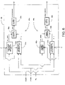
- These hardware structures (virtually) form a functional block as exemplified in FIG. 6 .
- FIG. 6 shows functional blocks related to control of the stroke adjustment by the adjustment motors 120 and 140.
- the control unit 160 comprises stroke adjustment control units 150a and 150b.
- the stroke adjustment control units 150a and 150b comprise line pressure measurement units 151a and 151b, pump chamber pressure measurement units 152a and 152b, pressure comparators 153a and 153b, and plunger adjusters 154a and 154b, respectively.
- the stroke adjustment control units 150a and 150b can be operated independently from each other. Contents of the calculations of the functional blocks of these control units will be described later.
- the ineffective stroke length d is set to 0. That is, the reciprocating motion drive forces of the crossheads 28 and 48 are transmitted to the plungers 26 and 46, respectively, without any loss. Further, the driving of the drive motor 11 is assumed to be a uniform velocity rotation. Moreover, in FIGs. 7 to 11 , various waveforms are exemplified in an ideal operation state in which no pulsation occurs.
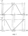
- FIG. 7 exemplifies graphs of positions, of the crossheads 28 and 48, in the X axis direction X_XH1 and X_XH2, with respect to a cam angle ⁇ of the rotation cam 15.
- the graphs show the cam angle ⁇ on a horizontal axis and the positions X_XH1 and X_XH2 of the crossheads 28 and 48 on a vertical axis.
- the bottom dead center BDC and the top dead center TDC are shown on the vertical axis.
- the graphs on an upper part and a lower part are synchronized.
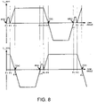
- FIG. 8 exemplifies changes of velocities of the crossheads 28 and 48 with respect to the cam angle ⁇ .
- the graphs of FIG. 8 show the cam angle ⁇ on a horizontal axis and reciprocating motion velocities V_XH1 and V_XH2 of the crossheads 28 and 48 on a vertical axis.
- a positive direction of the vertical axis shows a velocity in the forward movement direction.
- the graphs at an upper part and a lower part of FIG. 8 are synchronized.
- FIG. 9 exemplifies changes of inner pressures of the pump chambers 220 and 240, more accurately, the inner pressures of the hydraulic chambers 22 and 42 which are detection targets of the inner pressure sensors 64 and 65, with respect to the cam angle ⁇ .
- the graphs of FIG. 9 show the cam angle ⁇ on a horizontal axis and the inner pressures P_OR1 and P_OR2 of the hydraulic chambers 22 and 42 on a vertical axis.
- graphs at an upper part and a lower part of FIG. 9 are synchronized.
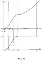
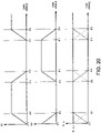
- FIG. 10 exemplifies a change of the position X_XH1 of the crosshead 28 (upper part) and a change of the inner pressure P_OR1 of the hydraulic chamber 22 (lower part), from the bottom dead center BDC of the crosshead 28 to the cam angle of ⁇ 3.
- the graphs at the upper part and the lower part of FIG. 10 are synchronized.
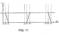
- FIG. 11 exemplifies the flow rate Q_L of the common discharge line 36.
- the graph of FIG. 11 shows the cam angle ⁇ on a horizontal axis, and the flow rate Q_L on a vertical axis.
- a narrow broken line shows a flow rate from the fluid chamber 25, and a thick broken line shows a flow rate from the fluid chamber 45.
- the rotation cam 15 is formed in such a shape that the crossheads 28 and 48 displace in a manner shown in the graphs of FIG. 7 corresponding to the cam angle ⁇ . More specifically, as exemplified in the upper part of FIG. 10 , the crosshead 28 displaces in the form of a concave-upward quadratic function, from a cam angle of ⁇ 1 at the bottom dead center BDC to a cam angle of ⁇ 1A.
- the crosshead 28 displaces in the form of a liner function (linearly) from a cam angle of ⁇ 1A to a cam angle of ⁇ 1B, and displaces in the form of a concave-downward quadratic function, from the cam angle of ⁇ 1B to a cam angle of ⁇ 2. Then, the crosshead 28 displaces in the form of a concave-upward quadratic function from the cam angle of ⁇ 2 to a cam angle of ⁇ 3, and displaces in the form of a linear function from the cam angle of ⁇ 3 to a cam angle of ⁇ 5.
- the crosshead 28 displaces in the form of a concave-downward quadratic function from the cam angle of ⁇ 5 to a cam angle of ⁇ 6, and reaches the top dead center TDC at the cam angle of ⁇ 6. From this point on, the crosshead 28 is put in the backward movement process, and the crosshead 28 moves backward while showing the waveform as shown in FIG. 7 from the cam angle of ⁇ 6 to the cam angle of ⁇ 1 at the bottom dead center.
- the crosshead 48 displaces with a phase difference of 180° with respect to the crosshead 28.
- ⁇ 1 0°
- ⁇ 2 30°
- ⁇ 3 60°.
- FIG. 8 shows the changes of the velocities of the crossheads 28 and 48 under the condition of the uniform rotation of the drive motor 11.
- the velocity of the crosshead 28 changes in a trapezoidal shape from the cam angle of ⁇ 1 to the cam angle of ⁇ 2. That is, with the displacement in the form of the concave-upward quadratic function from the cam angle of ⁇ 1 to the cam angle of ⁇ 1A, the velocity V_XH1 increases in the form of a linear function with a positive slope. Further, from the cam angle of ⁇ 1A to the cam angle of ⁇ 1B, according to the displacement in the form of the linear function, the slope of the velocity V_XH1 becomes constant. Moreover, from the cam angle of ⁇ 1B to the cam angle of ⁇ 2, according to the displacement in the form of the concave-downward quadratic function, the velocity V_XH1 is decreased in the form of a linear function with a negative slope.
- the inner pressure P_OR1 of the hydraulic chamber 22 increases.
- the inner pressure P_OR1 of the hydraulic chamber 22 becomes equal to the line pressure P_L, and the discharge valve 33 is switched from a closed state to an open state. With this process, the fluid (liquid) in the fluid chamber 25 is discharged to the common discharge line 36.
- the inner pressure P_OR1 of the hydraulic chamber 22 decreases with the backward movement of the crosshead 28.
- the intake valve 31 is switched from a closed state to an open state.
- the fluid is taken in from the common intake line 35 into the fluid chamber 25.
- the cam angle reaches the cam angle of ⁇ 1 corresponding to the bottom dead center of the crosshead 28, the crosshead again transitions to the forward movement process.
- the discharge valve 53 is set to the open state. From the cam angle of ⁇ 5 to the cam angle of 06, with the displacement (stroke) of the crosshead 48 in the form of the concave-upward quadratic function as shown in FIG. 7 , the flow rate of the fluid discharged from the fluid chamber 45 to the common discharge line 36 increases in the form of a linear function, as shown by a thick broken line of FIG. 11 .
- the period in which the flow rate from the fluid chamber 45 decreases from a constant state and the period in which the flow rate from the fluid chamber 25 increases to a constant state overlap each other in the period from the cam angle of ⁇ 2 to the cam angle of ⁇ 3.
- the period in which the flow rate from the fluid chamber 25 decreases from a constant state and the period in which the flow rate from the fluid chamber 45 increases to a constant state overlap each other in the period from the cam angle of ⁇ 5 to the cam angle of ⁇ 6.
- the fluid is supplied to the common discharge line 36 from both of the fluid chambers 25 and 45.
- the flow rate Q_L thereof is equal to the flow rate Q1 in a single discharge period ( ⁇ 3 to ⁇ 5) in which only the reciprocating pump 20 discharges the fluid to the common discharge line 36 and in a single discharge period ( ⁇ 6 to ⁇ 2) of the reciprocating pump 40.
- the flow rate of the common discharge line 36 is maintained at Q1 for all cam angles, and a fluid supply with no pulsation can be enabled.
- the waveforms of FIGs. 7 to 11 are determined based on, for example, the line pressure P_L of the common discharge line 36.
- a predetermined line pressure P_L is set in advance at the design stage.
- the shape of the rotation cam 15 is determined in advance such that the inner pressure P_OR1 of the hydraulic chamber 22 reaches the line pressure P_L at the cam angle of ⁇ 2, and the inner pressure P_OR2 of the hydraulic chamber 42 reaches the line pressure P_L at the cam angle of ⁇ 5.
- the cam angle ⁇ 2 which is set as the angle at which the inner pressure P_OR1 of the hydraulic chamber 22 reaches the line pressure P_L, and the cam angle ⁇ 5 which is set as the angle at which the inner pressure P_OR2 of the hydraulic chamber 42 reaches the line pressure P_L may each be called a discharge step starting point angle.
- the periods respectively from the bottom dead centers BDC of the crossheads 28 and 48 to the points in which the inner pressures P_OR1 and P_OR2 of the hydraulic chambers 22 and 42 reach the line pressure P_L may be considered as a compression step in which the hydraulic chambers 22 and 42 are compressed.
- the inner pressures P_OR1 and P_OR2 of the fluid chambers 25 and 45 and the hydraulic chambers 22 and 42 are respectively reduced to a pressure near atmospheric pressure.
- the inner pressures P_OR1 and P_OR2 of the fluid chambers 25 and 45 and the hydraulic chambers 22 and 42 are respectively increased to the line pressure P_L, for example, about 40 MPa.
- FIG. 12 shows a waveform when the actual line pressure P_L becomes a pressure P_L2 which is lower than the design reference value P_L1.
- the inner pressure P_OR1 of the hydraulic chamber 22 reaches the line pressure P_L2 before the cam angle of ⁇ 2 which is the discharge step starting point angle.
- the fluid would be discharged from the fluid chamber 25 during a period in which the amount of discharge from the fluid chamber 45 is a constant, and a pulsation exceeding the constant flow rate Q1 occurs.
- a similar pulsation occurs at the cam angles of 05 and 06, which are respectively a phase of 180° later.
- FIG. 13 shows a waveform when the actual line pressure P_L becomes a pressure P_L3 which is higher than the design reference value P_L1.
- the inner pressure P_OR1 of the hydraulic chamber 22 reaches the line pressure P_L3 after the cam angle ⁇ 2 which is the discharge step starting point angle.
- the discharge from the fluid chamber 25 would be started in a period in which the flow rate is gradually reduced after the period in which the discharge amount from the fluid chamber 45 is a constant, and a pulsation occurs in which the flow rate Q_L of the common discharge line 36 is less than the constant flow rate Q1.
- a similar pulsation occurs at the cam angles of 05 and ⁇ 6 which are respectively a phase of 180° later.
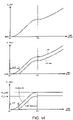
- FIG. 14 exemplifies a summary of the stroke adjustment control in the non-pulsating pump 100 of the present example useful for understanding the claimed invention.
- An upper part shows a change of the position (stroke) X_XH1 of the crosshead 28 corresponding to the cam angle.
- a middle part shows a change of the position (stroke) X_PG1 of the plunger 26 corresponding to the cam angle.
- a lower part shows a change of the inner pressure P_OR1 of the hydraulic chamber 22 corresponding to the cam angle.
- Graphs for the crosshead 48, the plunger 46, and the hydraulic chamber 42 would be graphs having a phase difference of 180° with respect to the corresponding graphs of FIG. 14 (these graphs are not shown).
- the stroke of the plunger 26 can be adjusted with respect to the crosshead 28 by the stroke adjustment mechanism 80.
- a parameter ⁇ shown in the middle part is a rotational angle of the rotation cam 15 (play angle) corresponding to the ineffective stroke length d.
- the maximum ineffective stroke length d_max is determined according to a range of a required pressure (pressure range) for the common discharge line 36 on which the non-pulsating pump 100 is installed.
- the maximum ineffective stroke length d_max and the shape of the rotation cam 15 are determined to satisfy the following two conditions.
- the play ranges of the plungers 26 and 46 that is, the ineffective stroke lengths d, are increased, to reduce a compression step amount.
- times for the pressure increase of the hydraulic chambers 22 and 42 can be delayed.
- the points in time when the inner pressures P_OR1 and P_OR2 of the hydraulic chambers 22 and 42 respectively reach the line pressure P_L2 can be respectively matched with the discharge step starting point angles ⁇ 2 and ⁇ 5.
- FIG. 15 exemplifies a flowchart of the stroke adjustment control by the stroke adjustment control unit 150a ( FIG. 6 ).
- the control unit 160 drives the drive motor 11 with the uniform rotation.
- the cam angle ⁇ of the rotation cam 15 is sent from the rotary encoder 130 to the pump chamber pressure measurement unit 152a and the line pressure measurement unit 151a.
- the line pressure measurement unit 151a determines whether or not the cam angle ⁇ is a predetermined cam angle ⁇ 7 ( ⁇ 3 ⁇ 07 ⁇ 05) in the single discharge steps ( ⁇ 3 ⁇ 05, and 06 ⁇ 02), while receiving the line pressure P_L (pipe pressure) from the line pressure sensor 63 (S16).
- the pressure comparator 153a acquires the inner pressure P_OR1 of the hydraulic chamber 22 at the discharge step starting point angle ⁇ 2 from the pump chamber pressure measurement unit 152a, acquires the line pressure P_L at the single discharge step from the line pressure measurement unit 151a, and compares these pressures (S22). More specifically, the pressure comparator 153a determines an absolute value of a difference between the pressures, and determines whether or not the determined absolute value exceeds a predetermined threshold D.
- the threshold D is a parameter which shows an allowable limit of pulsation in the process in which the non-pulsating pump 100 is used, and is, for example, arbitrarily set according to a customer request or the like.
- the effective stroke length is adjusted according to the difference value.
- the difference value ⁇ P is positive or negative (S24).
- the difference value is negative, that is, when P_OR1 ⁇ P_L, it means that the inner pressure P_OR1 of the hydraulic chamber 22 at the discharge step starting point angle ⁇ 2 is lower than the line pressure P_L in the single discharge step (the pattern as shown in FIG. 13 ).
- the effective stroke length is increased (extended), that is, the ineffective stroke length d is decreased (the range of the free reciprocating motion is contracted), so that the starting time of the compression step is moved forward.
- a range of the increase of the effective stroke length involved with the forward movement in time is determined based on the absolute value of the difference value.
- the plunger adjuster 154a stores the waveform of the inner pressure P_OR1 of the hydraulic chamber 22 with respect to arbitrary stroke effective lengths, and the increasing range ⁇ d of the stroke effective length, that is, a range of forward/backward movement of the stopper 82, is determined based on the difference value ⁇ P.
- the plunger adjuster 154a creates a backward movement command (play reduction command) for the adjustment motor 120 (and the stopper 82) based on pitches of the inner thread 28c and the outer thread 82d, a gear ratio of the worm gear 121 and the worm wheel 122, or the like, and transmits the command to the adjustment motor 120 (S28).
- the backward movement command may be, for example, a pulse signal.
- the difference value ⁇ P is positive, that is, when P_OR1 > P_L, it means that the inner pressure P_OR1 of the hydraulic chamber 22 at the discharge step starting point angle ⁇ 2 exceeds the line pressure P_L at the single discharge step (the pattern of FIG. 12 ).
- the effective stroke length is decreased (shortened), that is, the ineffective stroke length d is increased (the range of the free reciprocating motion is extended), so that the starting point of the compression step is delayed.
- a reduction range of the effective stroke length involved with the delay is determined according to the absolute value of the difference value
- the plunger adjuster 154a creates a forward movement command (play increasing command) for the adjustment motor 120 (and the stopper 82), and transmits the command to the adjustment motor 120 (S26).
- the forward movement command may be, for example, a pulse signal.
- the control unit 160 determines whether or not a stopping command for the non-pulsating pump 100 is output (S30). When the stopping command is output, the present flow is completed, and when the stopping command is not output, the process returns to step S10.
- the positions of the top dead center and the bottom dead center of the plunger 26 change.
- the diaphragm 23 is recessed on the side of the hydraulic chamber 22 so that the hydraulic chamber 22 and the fluid chamber 25 are at the same pressure.
- step S10 the discharge step starting point angle at the step S10 is changed from ⁇ 2 to ⁇ 5
- the inner pressure of the hydraulic chamber at the steps S14, S22, and S24 is changed from P_OR1 to P_OR2.
- step S16 the phase difference of 180° is added to the angle ⁇ 7 in the single discharge step.
- the effective stroke length is adjusted such that the points in time when the inner pressures P_OR1 and P_OR2 of the hydraulic chambers 22 and 42 respectively reach the line pressure P_L at the predetermined angle ⁇ 7 in the single discharge step are matched to the discharge step starting point angles ⁇ 2 and ⁇ 5, respectively.
- the pulsation can be suppressed with higher precision in comparison to, for example, adjustment of the effective stroke length based on the pulsation waveform.
- FIG. 16 exemplifies a non-pulsating pump 100 according to the claimed invention. Elements assigned the same reference numerals as those shown in FIG. 1 have basically the same structures, and will not be described again.
- hydraulic pressure adjustment mechanisms 320 and 340 are provided respectively in the hydraulic chambers 22 and 42.
- the hydraulic pressure adjustment mechanism 320 and 340 can adjust the inner pressures of the pump chambers 220 and 240, respectively. That is, the hydraulic pressure adjustment mechanisms 320 and 340 can adjust times of increases of the inner pressures of the hydraulic chambers 22 and 42, respectively.
- the inner pressures P_OR1 and P_OR2 of the hydraulic chambers 22 and 42 are adjusted so that points in time when the inner pressures P_OR1 and P_OR2 of the hydraulic chambers 22 and 42 respectively reach the line pressure P_L at the predetermined angle ⁇ 7 in the single discharge step are matched to the discharge step starting point angles ⁇ 2 and ⁇ 5, respectively.
- the hydraulic pressure adjustment mechanisms 320 and 340 may also be called compression amount adjustment mechanisms.
- the hydraulic pressure adjustment mechanisms 320 and 340 are attached at sides of the reciprocating pumps 20 and 40, but the form of attachment is not limited to this form.
- the hydraulic pressure adjustment mechanisms 320 and 340 may be attached above the reciprocating pumps 20 and 40. With such a configuration, it becomes easier for air in the reciprocating pumps 20 and 40 to enter the hydraulic pressure adjustment mechanisms 320 and 340, and consequently, a degassing mechanism (not shown) may be provided in parallel to the hydraulic pressure adjustment mechanisms 320 and 340.
- FIG. 17 an example configuration is shown in which the hydraulic pressure adjustment mechanisms 320 and 340 are attached above the reciprocating pumps 20 and 40.
- FIG. 17 exemplifies a side cross sectional diagram of the hydraulic pressure adjustment mechanism 320.
- the hydraulic pressure adjustment mechanism 320 comprises an adapter 3214, a piston 3216, a coil spring 3218, a screw 3222, a coupling 3224, a drive shaft 3232, a decelerator 3212, and an adjustment motor 3220.
- the hydraulic pressure adjustment mechanism 340 on the side of the reciprocating pump 40 has a similar structure to the hydraulic pressure adjustment mechanism 320. More specifically, in the following description, the number "2" at the hundreds digit position may be replaced with "4" in the reference numerals of the elements, to describe the structure of the hydraulic pressure adjustment mechanism 340 on the side of the reciprocating pump 40.
- the hydraulic pressure adjustment mechanism 320 is attached above a hydraulic chamber case 3236 which is a member partitioning the hydraulic chamber 22.
- a hydraulic chamber case 3236 which is a member partitioning the hydraulic chamber 22.
- an upper part of the hydraulic chamber case 3236 has a U shape cross section, and an attachment hole 3236a formed in an up-and-down direction (Z axis direction) is formed for receiving the adapter 3214, the piston 3216, the screw 3222, and the like.
- an opening 3236b is formed in communication with the hydraulic chamber 22.
- the adapter 3214 is a cap member having a cross section of a U shape, and is fixed in the attachment hole 3236a of the hydraulic chamber case 3236.
- an outer thread is formed on an outer circumferential surface of the adapter 3214, and an inner thread is formed on an inner circumferential surface of the attachment hole 3236a. The threads are screwed together, so that the adapter 3214 is fixed in the attachment hole 3236a.
- An opening 3214a in communication with the opening 3236b of the hydraulic chamber case 3236 is formed to penetrate through a lower end (bottom) of the adapter 3214 in the up-and-down direction. Thus, the oil in the hydraulic chamber 22 can flow into the adapter 3214.
- the piston 3216 is housed at an inner bottom of the adapter 3214.
- the piston 3216 has, for example, a U shape cross section, and the coil spring 3218 is inserted inside the piston 3216.
- the piston 3216 is pushed upward by the oil flowing in from the hydraulic chamber 22.
- a sealing member such as an O ring may be sandwiched between an outer circumferential surface of the piston and an inner circumferential surface of the adapter 3214.
- a lower end of the coil spring 3218 abuts an inner bottom of the piston 3216, and an upper end of the coil spring 3218 abuts a lower end surface 3222a of the screw 3222.
- the piston 3216 is urged downward by the elastic force of the coil spring 3218, and prevents intrusion of the oil above the opening 3214a of the adapter 3214.
- the inner pressure P_OR1 of the hydraulic chamber 22 increases and reaches a pressure greater than or equal to the elastic pressure of the coil spring 3218, the coil spring 3218 contracts and the piston 3216 moves backward (upward).
- a movement range of the piston 3216 that is, the stroke length d, is changed, to adjust the inner pressure (at the time of increasing the inner pressure ) of the hydraulic chamber 22.
- the screw 3222 has an approximately circular column shape, and is housed in the adapter 3214.
- An outer thread 3222b is formed on the outer circumferential surface of the adapter 3214, and is screwed into the inner thread 3214b formed on the inner circumferential surface of the adapter 3214.
- a rotational drive force is transmitted to the screw 3222 from the adjustment motor 3220. More specifically, the rotational drive force is transmitted from the adjustment motor 3220 through the decelerator 3212, the drive shaft 3232, a key 3230, the coupling 3224, and a key 3226, to the screw 3222.
- the adjustment motor 3220 is formed from, for example, a reversible motor.
- the drive shaft 3232 is provided at a lower end of the decelerator 3212, and is placed to be coaxial with the screw 3222.
- a stopper 3228 for example, is provided between a lower end of the drive shaft 3232 and the screw 3222. The stopper 3228 determines a maximum elevation point of the screw 3222, and abuts an upper end of the screw 3222 moving upward.
- the drive shaft 3232 is connected to the coupling 3224 via the key 3230.
- the coupling 3224 is a circular tubular member provided at an outer circumference of the drive shaft 3232 and the screw 3222, and rotates with the drive shaft 3232.
- a key groove 3224a which is formed in the up-and-down direction is formed on an inner circumferential surface of the coupling 3224.
- the key 32226 is slidable in the key groove 3224a.
- the key 3226 is fixed on the screw 3222, and protrudes in an outer side in a radial direction, and the protruding portion is fitted in the key groove 3224a in a slidable manner.
- the screw 3222 can relatively move in the up-and-down direction with respect to the coupling 3224, with regard to the rotational direction, the screw 3222 rotates with the coupling 3224 due to the fitted relationship of the key groove 3224a and the key 3226.
- the inner pressure P_OR1 of the hydraulic chamber 22 increases.
- the pressure (inner pressure) received by the lower surface (front surface) of the piston 3216 of the hydraulic pressure adjustment mechanism 320 increases.
- this inner pressure exceeds the elastic pressure of the coil spring 3218, the coil spring 3218 is contracted, and the piston 3216 is moved upward.
- the stroke length d is shortened.
- the crosshead 28 After the crosshead 28 reaches the top dead center, the crosshead 28 moves backward, and the inner pressure P_OR1 of the hydraulic chamber 22 decreases. In this process, the coil spring 3218 urges the piston 3216 downward. With the urging, the lower end surface 3216b of the piston 3216 abuts a bottom surface 3214c at an inner side of the adapter 3214. With this process, the stroke length d is secured. After the crosshead 28 reaches the bottom dead center, that is, a point farthest away from the pump chamber 220, the crosshead 28 again moves forward.
- FIG. 18 exemplifies functional blocks of the control unit 160 for executing the pump chamber inner pressure adjustment control of the present embodiment in accordance with the claimed invention.
- FIG. 18 differs from FIG. 6 in that pump chamber inner pressure adjustment control units 350a and 350b are provided in place of the stroke adjustment control units 150a and 150b.
- piston adjusters 155a and 155b are provided in place of the plunger adjusters 154a and 154b.
- FIG. 19 exemplifies a summary of the pump chamber inner pressure adjustment control in the non-pulsating pump 100 of the present embodiment in accordance with the claimed invention.
- control of the pump chamber inner pressure adjustment control unit 350a will be described.
- An upper part of FIG. 19 shows a change of the position (stroke) X_XH1 of the crosshead 28 corresponding to the cam angle.
- a lower part of FIG. 19 shows a change of the inner pressure P_OR1 of the hydraulic chamber 22 corresponding to the cam angle.
- the crosshead 48, the plunger 46, and the hydraulic chamber 42 would have graphs (which will not be shown) having a phase difference of 180° with respect to the graphs of FIG. 19 .
- the maximum stroke length d_max is determined according to a range of a required pressure (pressure range) for the common discharge line 36 on which the non-pulsating pump 100 is installed.
- the maximum stroke length d_max and the shape of the rotation cam 15 are determined to satisfy the following two conditions.
- the stroke length d of the piston 3216 is increased, to reduce the compression step amount.
- the times when pressures of the hydraulic chambers 22 and 42 are increased are delayed. With this process, it becomes possible to match the points in time when the inner pressures P_OR1 and P_OR2 of the hydraulic chambers 22 and 42 reach the line pressure P_L2 with the discharge step starting point angles ⁇ 2 and ⁇ 5.
- a flowchart of the pump chamber inner pressure adjustment control by the control unit 160 is identical to the flowchart of FIG. 15 showing the stroke adjustment control, except that, in steps S26 and S28, the piston adjusters 155a and 155b respectively output a forward movement command (play increasing command) and a backward movement command (play decreasing command) to the adjustment motors 3220 and 3420, respectively.
- the stroke length d of the piston 3216 is adjusted corresponding to a difference value.
- step S24 it is determined whether the difference value ⁇ P is positive or negative.
- the difference value is negative, that is, P_OR1 ⁇ P_L
- the inner pressure P_OR1 of the hydraulic chamber 22 at the discharge step starting point angle ⁇ 2 is lower than the line pressure P_L at the single discharge step.
- the stroke length d is decreased (the range of the free reciprocating motion is reduced), so as to move the starting point of the compression step forward.
- An increase range of the stroke length involved with the forward movement in time is determined according to the absolute value of the difference value.
- the piston adjuster 155a stores a waveform of the inner pressure P_OR1 of the hydraulic chamber 22 corresponding to an arbitrary stroke length, and the increase range ⁇ d of the stroke length, that is, a forward/backward movement range of the screw 3222, is determined based on the difference value ⁇ P.
- the piston adjuster 155a creates the backward movement command (play decreasing command) for the adjustment motor 3220 (and the screw 3222) based on pitches of the inner thread 3214b and the outer thread 3222b, the deceleration ratio of the decelerator 3212, or the like, and transmits the command to the adjustment motor 3220 (S28). With the backward movement driving of the adjustment motor 3220, the screw 3222 moves backward, and the stroke length d is decreased.
- the piston adjuster 155a creates a forward movement command (play increasing command) for the adjustment motor 3220 (and the screw 3222), and transmits the command to the adjustment motor 3220 (S26).
- the forward movement command may be, for example, a pulse signal.
- step S10 the discharge step starting point angle ⁇ 2 becomes ⁇ 5, and, in steps S14, S22, and S24, the inner pressure P_OR1 of the hydraulic chamber is replaced with P_OR2.
- step S16 a phase difference of 180° is added to the angle ⁇ 7 in the single discharge step.
- the stroke length d of the piston 3216 is adjusted such that the points in time when the inner pressures P_OR1 and P_OR2 of the hydraulic chambers 22 and 42, respectively, reach the line pressure P_L at the predetermined angle ⁇ 7 in the single discharge step are the discharge step starting point angles ⁇ 2 and ⁇ 5, respectively.
- the pulsation can be suppressed with a higher precision in comparison to a case in which the stroke length is adjusted, for example, based on a pulsation waveform.
Landscapes
- Engineering & Computer Science (AREA)
- Mechanical Engineering (AREA)
- General Engineering & Computer Science (AREA)
- Reciprocating Pumps (AREA)
- Pipe Accessories (AREA)
Claims (2)
- Eine nicht pulsierende Pumpe (100), die Folgendes umfasst:einen Antriebsmechanismus (250) mit: einem Nockenmechanismus (16), der eine Drehbewegung eines Antriebsmotors (11) in eine hin- und hergehende Bewegung umwandelt; und eine Vielzahl von Kreuzköpfen (28, 48), die durch den Nockenmechanismus (16) mit einer vorbestimmten Phasendifferenz hin- und herbewegt werden;eine Mehrzahl von Kolbenpumpen (20, 40), die jeweils aufweisen: einen Kolben (26; 46), der mit dem Kreuzkopf (28; 48) verbunden ist und der sich mit der hin- und hergehenden Bewegung hin- und herbewegt; eine Pumpenkammer (220; 240), die eine Hydraulikkammer (22; 42), in die ein Teil des Kolbens (26; 46) eingesetzt ist, und eine von der Hydraulikkammer (22; 42) durch eine Membran (23; 43) getrennte Fluidkammer (25; 45) umfasst, und in der sich Innendrücke der Hydraulikkammer (22; 42) und der Fluidkammer (25; 45) mit der Hin- und Herbewegung des Kolbens (26; 46) ändern; ein Einlassventil (31; 51), das eine gemeinsame Einlassleitung (35) und die Fluidkammer (25; 45) verbindet und das eine Seite der Fluidkammer (25; 45) als eine Gegendruckseite aufweist; ein Auslassventil (33; 53), das die Fluidkammer (25; 45) und eine gemeinsame Auslassleitung (36) verbindet und das eine Seite der gemeinsamen Auslassleitung (36) als eine Gegendruckseite aufweist; und einen Innendruckeinstellmechanismus (320; 340), der den Innendruck der Hydraulikkammer (26; 46) einstellen kann; undeine Steuereinheit (160), die den Innendruckeinstellmechanismus (320; 340) steuert, wobeiein Innendrucksensor (64; 65), der den Innendruck der Hydraulikkammer misst, an jeder der Kolbenpumpen vorgesehen ist, unddie Steuereinheit (160) konfiguriert ist, um:von dem Innendrucksensor (64; 65), der an einer vorbestimmten Kolbenpumpe (20; 40) vorgesehen ist, einen Startpunktwinkel-Innendruck zu erfassen, der der Innendruck der Hydraulikkammer (22; 42) der vorbestimmten Kolbenpumpe (20; 40) bei einem Ausstoßschritt-Startpunktwinkel ist, der entsprechend einem Nockenwinkel des Nockenmechanismus (16) bezüglich der vorbestimmten Kolbenpumpe (20; 40) bestimmt wird;vom dem an einer Kolbenpumpe (20; 40) vorgesehenen Innendrucksensor (64; 65) aus der Mehrzahl von Kolbenpumpen (20, 40), die eine andere als die vorbestimmte Kolbenpumpe (20; 40) ist, einen einzelnen Auslasszeit-Innendruck zu erfassen, der der Innendruck der Hydraulikkammer (26; 46) der einen Kolbenpumpe (20; 40) bei einem einzelnen Auslassschritt ist, in dem nur die eine Kolbenpumpe (20; 40) Fluid zu der gemeinsamen Auslassleitung (36) ausstößt; undden Innendruck-Einstellmechanismus (320; 340) zu veranlassen, den Innendruck der Hydraulikkammer (22; 42) der vorbestimmten Kolbenpumpe (20; 40) auf der Grundlage einer Druckdifferenz zwischen dem erfassten Startpunktwinkel-Innendruck und dem erfassten einzelnen Auslasszeit-Innendruck einzustellen, so dass der Innendruck der Hydraulikkammer (22; 42) der vorbestimmten Kolbenpumpe (20; 40) einen Wert erreicht, der gleich dem einzelnen Auslasszeit-Innendruck bei dem Auslassschritt-Startpunktwinkel ist.
- Verfahren zum Steuern einer nicht pulsierenden Pumpe (100), wobei die nicht pulsierende Pumpe (100) umfasst:einen Antriebsmechanismus (250) mit: einem Nockenmechanismus (16), der eine Drehbewegung eines Antriebsmotors (11) in eine Hin- und Herbewegung umwandelt; und einer Vielzahl von Kreuzköpfen (28; 48), die durch den Nockenmechanismus (16) mit einer vorbestimmten Phasendifferenz hin- und herbewegt werden; undeine Mehrzahl von Kolbenpumpen (20, 40), die jeweils aufweisen: einen Kolben (26; 46), der mit dem Kreuzkopf (28; 48) verbunden ist und der sich mit der hin- und hergehenden Bewegung des Kreuzkopfes (28; 48) hin- und herbewegt; eine Pumpenkammer (220; 240), die eine Hydraulikkammer (22; 42), in die ein Teil des Kolbens (26; 46) eingesetzt ist, und von der Hydraulikkammer (22; 42) durch eine Membran (23; 43) getrennte Fluidkammer (25; 45), und in der sich Innendrücke der Hydraulikkammer (22; 42) und der Fluidkammer (25; 45) mit der Hin- und Herbewegung des Kolbens (26; 46) ändern; ein Einlassventil (31; 51), das eine gemeinsame Einlassleitung (35) und die Fluidkammer (25; 45) verbindet und das eine Seite der Fluidkammer (25; 45) als Gegendruckseite aufweist; ein Auslassventil (33; 54), das die Fluidkammer (25; 45) und eine gemeinsame Auslassleitung (36) verbindet und das eine Seite der gemeinsamen Auslassleitung (36) als eine Gegendruckseite aufweist; und einen Innendruckeinstellmechanismus (320; 340), der den Innendruck der Hydraulikkammer (22; 42) einstellen kann; wobei ein Innendrucksensor (64; 65), der den Innendruck der Hydraulikkammer (22; 42) misst, an jeder der Kolbenpumpen (20, 40) vorgesehen ist,ein Startpunktwinkel-Innendruck, der der Innendruck der Hydraulikkammer (22; 42) einer vorbestimmten Kolbenpumpe (20; 40) bei einem entsprechend einem Nockenwinkel des Nockenmechanismus (16) bezüglich der vorbestimmten Hubkolbenpumpe (20; 40) ermittelten Auslassschritt-Startpunktwinkel ist, von dem Innendrucksensor (64; 65), der an der vorbestimmten Kolbenpumpe (20; 40) vorgesehen ist, ermittelt wird, ein einzelner Auslasszeit-Innendruck, der der Innendruck der Hydraulikkammer (22; 42) einer Kolbenpumpe (20; 40) unter der Vielzahl von Hubkolbenpumpen (20, 40), welche eine andere als die vorbestimmte Kolbenpumpe (20; 40) ist, bei einem einzelnen Auslassschritt erfasst wird, bei dem nur die eine Hubkolbenpumpe (20; 40) Fluid zu der gemeinsamen Auslassleitung (36) ausstößt, von dem Innendrucksensor (64; 65) erfasst wird, der an der einen Kolbenpumpe (20; 40) vorgesehen ist, undder Innendruckeinstellmechanismus (320; 340) den Innendruck der Hydraulikkammer (22; 42) der vorbestimmten Kolbenpumpe (20; 40) basierend auf einer Druckdifferenz zwischen dem erfassten Startpunktwinkel-Innendruck und dem erfassten einzelnen Auslasszeit-Innendruck anpasst, sodass der Innendruck der Hydraulikkammer (22; 42) der vorbestimmten Kolbenpumpe (20; 40) einen Wert erreicht, der gleich dem einzelnen Auslasszeit-Innendruck beim Auslassschritt-Startpunktwinkel ist.
Applications Claiming Priority (3)
| Application Number | Priority Date | Filing Date | Title |
|---|---|---|---|
| JP2018061702A JP6952636B2 (ja) | 2018-03-28 | 2018-03-28 | 無脈動ポンプ及び無脈動ポンプの制御方法 |
| PCT/JP2019/009665 WO2019188184A1 (ja) | 2018-03-28 | 2019-03-11 | 無脈動ポンプ |
| EP19774824.7A EP3779190B1 (de) | 2018-03-28 | 2019-03-11 | Pulsationsfreie pumpe |
Related Parent Applications (2)
| Application Number | Title | Priority Date | Filing Date |
|---|---|---|---|
| EP19774824.7A Division EP3779190B1 (de) | 2018-03-28 | 2019-03-11 | Pulsationsfreie pumpe |
| EP19774824.7A Division-Into EP3779190B1 (de) | 2018-03-28 | 2019-03-11 | Pulsationsfreie pumpe |
Publications (2)
| Publication Number | Publication Date |
|---|---|
| EP3865708A1 EP3865708A1 (de) | 2021-08-18 |
| EP3865708B1 true EP3865708B1 (de) | 2022-05-04 |
Family
ID=68061696
Family Applications (2)
| Application Number | Title | Priority Date | Filing Date |
|---|---|---|---|
| EP19774824.7A Active EP3779190B1 (de) | 2018-03-28 | 2019-03-11 | Pulsationsfreie pumpe |
| EP21167793.5A Active EP3865708B1 (de) | 2018-03-28 | 2019-03-11 | Nicht-pulsierende pumpe |
Family Applications Before (1)
| Application Number | Title | Priority Date | Filing Date |
|---|---|---|---|
| EP19774824.7A Active EP3779190B1 (de) | 2018-03-28 | 2019-03-11 | Pulsationsfreie pumpe |
Country Status (7)
| Country | Link |
|---|---|
| US (1) | US11486374B2 (de) |
| EP (2) | EP3779190B1 (de) |
| JP (1) | JP6952636B2 (de) |
| KR (1) | KR102643615B1 (de) |
| CN (1) | CN111936743B (de) |
| TW (1) | TWI791800B (de) |
| WO (1) | WO2019188184A1 (de) |
Families Citing this family (7)
| Publication number | Priority date | Publication date | Assignee | Title |
|---|---|---|---|---|
| KR102152058B1 (ko) * | 2019-11-19 | 2020-09-04 | 광성지엠(주) | 멀티 주입 펌프 |
| CA3200839A1 (en) * | 2020-11-09 | 2022-05-12 | Pdc Machines Inc. | Active oil injection system for a diaphragm compressor |
| AU2023277540A1 (en) * | 2022-05-26 | 2024-12-05 | Schwing Bioset, Inc. | Continuous flow multi-piston pump |
| CN115095626A (zh) * | 2022-08-03 | 2022-09-23 | 南京信息工程大学 | 一种工作在阀模式的旋转型磁流变液阻尼器 |
| CN119508194B (zh) * | 2023-08-22 | 2025-05-30 | 浙江力高泵业科技有限公司 | 一种具有无脉动恒定流量输出的液压隔膜计量泵 |
| CN119062539A (zh) * | 2024-10-31 | 2024-12-03 | 杭州精进科技有限公司 | 一种高精度无弹簧的多柱塞动力机构 |
| CN120212019B (zh) * | 2025-05-28 | 2025-08-12 | 大连里瓦泵业有限公司 | 一种双单元无脉动计量泵 |
Family Cites Families (30)
| Publication number | Priority date | Publication date | Assignee | Title |
|---|---|---|---|---|
| US1927587A (en) * | 1930-07-19 | 1933-09-19 | Marcus L Hacker | Diaphragm pump |
| US3809507A (en) * | 1972-03-01 | 1974-05-07 | B Baglai | Nonpulsating fluid-flow pump |
| DE2446805A1 (de) | 1974-10-01 | 1976-04-08 | Ott Kg Lewa | Pulsationsfrei arbeitende dosierpumpe |
| US4003679A (en) * | 1975-04-02 | 1977-01-18 | Hewlett-Packard Company | High pressure pump with metering |
| US4171191A (en) * | 1976-03-25 | 1979-10-16 | Krueger Wallace F | Apparatus for transferring metered quantities of material from one location to another |
| US4359312A (en) | 1978-08-15 | 1982-11-16 | Zumtobel Kg | Reciprocating pump for the pulsation-free delivery of a liquid |
| EP0100149A1 (de) * | 1982-07-05 | 1984-02-08 | Vfp Fluid Power Limited | Membranpumpe |
| JPS5970085U (ja) * | 1982-11-02 | 1984-05-12 | 日本電子株式会社 | ポンプ機構 |
| JPS6067790A (ja) | 1983-09-21 | 1985-04-18 | Tokyo Rika Kikai Kk | 液体クロマトグラフイ−等の高圧定量ポンプ装置 |
| JPH0326306Y2 (de) | 1985-04-03 | 1991-06-06 | ||
| JPS6371586A (ja) * | 1986-09-12 | 1988-03-31 | Yokogawa Electric Corp | 送液装置 |
| JP3507212B2 (ja) * | 1994-08-23 | 2004-03-15 | 日機装株式会社 | 無脈動ポンプ |
| US5993174A (en) | 1994-08-23 | 1999-11-30 | Nikkiso Co., Ltd. | Pulsation free pump |
| JP3508378B2 (ja) * | 1996-03-28 | 2004-03-22 | 株式会社スギノマシン | 液体加圧装置 |
| JP2004044471A (ja) * | 2002-07-11 | 2004-02-12 | Nikkiso Co Ltd | 無脈動ポンプ |
| JP2004108188A (ja) * | 2002-09-17 | 2004-04-08 | Nikkiso Co Ltd | 無脈動ポンプ |
| JP4276827B2 (ja) | 2002-10-18 | 2009-06-10 | 株式会社日立ハイテクノロジーズ | 液体クロマトグラフ用ポンプ及びその運転方法 |
| JP2004150402A (ja) | 2002-11-01 | 2004-05-27 | Hitachi High-Technologies Corp | 液体クロマトグラフ用ポンプ |
| JP3861060B2 (ja) * | 2003-01-31 | 2006-12-20 | 日機装株式会社 | 無脈動ポンプ |
| JP2006052646A (ja) * | 2004-08-09 | 2006-02-23 | Reika Kogyo Kk | 定量ポンプ装置 |
| JP2007327449A (ja) * | 2006-06-09 | 2007-12-20 | Nikkiso Co Ltd | 無脈動ポンプ |
| US7677872B2 (en) | 2007-09-07 | 2010-03-16 | Gm Global Technology Operations, Inc. | Low back-flow pulsation fuel injection pump |
| JP5266012B2 (ja) * | 2008-10-21 | 2013-08-21 | 日機装株式会社 | 無脈動ポンプ |
| JP5624825B2 (ja) | 2010-07-29 | 2014-11-12 | 株式会社日立ハイテクノロジーズ | 液体クロマトグラフ用ポンプ、および液体クロマトグラフ |
| JP5342605B2 (ja) * | 2011-06-24 | 2013-11-13 | 日機装株式会社 | 無脈動ポンプ |
| JP2013029080A (ja) * | 2011-07-29 | 2013-02-07 | Nikkiso Co Ltd | 無脈動ポンプ |
| JP2013032738A (ja) * | 2011-08-02 | 2013-02-14 | Nikkiso Co Ltd | ダイアフラムポンプ |
| CN108291897B (zh) * | 2015-11-26 | 2021-04-09 | 株式会社岛津制作所 | 送液装置、送液装置的送液控制方法以及送液装置的送液控制程序 |
| JP6305480B2 (ja) | 2016-09-01 | 2018-04-04 | 日機装株式会社 | 無脈動ポンプ |
| JP6313827B2 (ja) * | 2016-09-07 | 2018-04-18 | 日機装株式会社 | 無脈動ポンプ |
-
2018
- 2018-03-28 JP JP2018061702A patent/JP6952636B2/ja active Active
-
2019
- 2019-03-11 EP EP19774824.7A patent/EP3779190B1/de active Active
- 2019-03-11 CN CN201980019912.4A patent/CN111936743B/zh active Active
- 2019-03-11 US US16/981,222 patent/US11486374B2/en active Active
- 2019-03-11 WO PCT/JP2019/009665 patent/WO2019188184A1/ja not_active Ceased
- 2019-03-11 KR KR1020207027624A patent/KR102643615B1/ko active Active
- 2019-03-11 EP EP21167793.5A patent/EP3865708B1/de active Active
- 2019-03-22 TW TW108110040A patent/TWI791800B/zh active
Also Published As
| Publication number | Publication date |
|---|---|
| US11486374B2 (en) | 2022-11-01 |
| EP3779190A1 (de) | 2021-02-17 |
| JP2019173634A (ja) | 2019-10-10 |
| EP3779190A4 (de) | 2021-12-15 |
| CN111936743A (zh) | 2020-11-13 |
| US20210025375A1 (en) | 2021-01-28 |
| JP6952636B2 (ja) | 2021-10-20 |
| TWI791800B (zh) | 2023-02-11 |
| WO2019188184A1 (ja) | 2019-10-03 |
| CN111936743B (zh) | 2022-05-17 |
| KR102643615B1 (ko) | 2024-03-05 |
| EP3865708A1 (de) | 2021-08-18 |
| KR20200138236A (ko) | 2020-12-09 |
| TW201942468A (zh) | 2019-11-01 |
| EP3779190B1 (de) | 2023-05-10 |
Similar Documents
| Publication | Publication Date | Title |
|---|---|---|
| EP3865708B1 (de) | Nicht-pulsierende pumpe | |
| EP3149329B1 (de) | Vorrichtung zur verhinderung von mechanischem spiel bei motorgetriebenen komponenten in präzisionssystemen und verwendungen | |
| US9410543B2 (en) | Pump for liquid chromatograph, and liquid chromatograph | |
| US10890166B2 (en) | Non-pulsation pump having stroke adjustment mechanism | |
| US4687426A (en) | Constant volume pulsation-free reciprocating pump | |
| US20180306179A1 (en) | Zero pulsation pump | |
| KR102878487B1 (ko) | 정용량형 펌프에서 유동의 전자 조절용 기구 | |
| EP4388197B1 (de) | Kalibrierbare pumpe mit variabler verdrängung | |
| EP3207250B1 (de) | Verdrängerpumpe sowie pumpengruppe für flüssige produkte und verfahren zur verwendung davon | |
| EP0265591B1 (de) | Pumpe mit oszillierender Bewegung | |
| US12535467B2 (en) | Linear actuator for chromatography | |
| HK40123185A (en) | Mechanism for electronic adjustment of flows in fixed displacement pump | |
| HK40123184A (en) | Mechanism for electronic adjustment of flows in fixed displacement pump | |
| JPH0754115B2 (ja) | 往復ポンプ |
Legal Events
| Date | Code | Title | Description |
|---|---|---|---|
| PUAI | Public reference made under article 153(3) epc to a published international application that has entered the european phase |
Free format text: ORIGINAL CODE: 0009012 |
|
| STAA | Information on the status of an ep patent application or granted ep patent |
Free format text: STATUS: THE APPLICATION HAS BEEN PUBLISHED |
|
| AC | Divisional application: reference to earlier application |
Ref document number: 3779190 Country of ref document: EP Kind code of ref document: P |
|
| AK | Designated contracting states |
Kind code of ref document: A1 Designated state(s): AL AT BE BG CH CY CZ DE DK EE ES FI FR GB GR HR HU IE IS IT LI LT LU LV MC MK MT NL NO PL PT RO RS SE SI SK SM TR |
|
| STAA | Information on the status of an ep patent application or granted ep patent |
Free format text: STATUS: REQUEST FOR EXAMINATION WAS MADE |
|
| 17P | Request for examination filed |
Effective date: 20210901 |
|
| RBV | Designated contracting states (corrected) |
Designated state(s): AL AT BE BG CH CY CZ DE DK EE ES FI FR GB GR HR HU IE IS IT LI LT LU LV MC MK MT NL NO PL PT RO RS SE SI SK SM TR |
|
| GRAP | Despatch of communication of intention to grant a patent |
Free format text: ORIGINAL CODE: EPIDOSNIGR1 |
|
| STAA | Information on the status of an ep patent application or granted ep patent |
Free format text: STATUS: GRANT OF PATENT IS INTENDED |
|
| INTG | Intention to grant announced |
Effective date: 20211223 |
|
| GRAS | Grant fee paid |
Free format text: ORIGINAL CODE: EPIDOSNIGR3 |
|
| GRAA | (expected) grant |
Free format text: ORIGINAL CODE: 0009210 |
|
| STAA | Information on the status of an ep patent application or granted ep patent |
Free format text: STATUS: THE PATENT HAS BEEN GRANTED |
|
| AC | Divisional application: reference to earlier application |
Ref document number: 3779190 Country of ref document: EP Kind code of ref document: P |
|
| AK | Designated contracting states |
Kind code of ref document: B1 Designated state(s): AL AT BE BG CH CY CZ DE DK EE ES FI FR GB GR HR HU IE IS IT LI LT LU LV MC MK MT NL NO PL PT RO RS SE SI SK SM TR |
|
| REG | Reference to a national code |
Ref country code: GB Ref legal event code: FG4D |
|
| REG | Reference to a national code |
Ref country code: CH Ref legal event code: EP |
|
| REG | Reference to a national code |
Ref country code: AT Ref legal event code: REF Ref document number: 1489307 Country of ref document: AT Kind code of ref document: T Effective date: 20220515 |
|
| REG | Reference to a national code |
Ref country code: IE Ref legal event code: FG4D Ref country code: DE Ref legal event code: R096 Ref document number: 602019014688 Country of ref document: DE |
|
| REG | Reference to a national code |
Ref country code: SE Ref legal event code: TRGR |
|
| REG | Reference to a national code |
Ref country code: LT Ref legal event code: MG9D |
|
| REG | Reference to a national code |
Ref country code: NL Ref legal event code: MP Effective date: 20220504 |
|
| REG | Reference to a national code |
Ref country code: AT Ref legal event code: MK05 Ref document number: 1489307 Country of ref document: AT Kind code of ref document: T Effective date: 20220504 |
|
| PG25 | Lapsed in a contracting state [announced via postgrant information from national office to epo] |
Ref country code: PT Free format text: LAPSE BECAUSE OF FAILURE TO SUBMIT A TRANSLATION OF THE DESCRIPTION OR TO PAY THE FEE WITHIN THE PRESCRIBED TIME-LIMIT Effective date: 20220905 Ref country code: NO Free format text: LAPSE BECAUSE OF FAILURE TO SUBMIT A TRANSLATION OF THE DESCRIPTION OR TO PAY THE FEE WITHIN THE PRESCRIBED TIME-LIMIT Effective date: 20220804 Ref country code: NL Free format text: LAPSE BECAUSE OF FAILURE TO SUBMIT A TRANSLATION OF THE DESCRIPTION OR TO PAY THE FEE WITHIN THE PRESCRIBED TIME-LIMIT Effective date: 20220504 Ref country code: LT Free format text: LAPSE BECAUSE OF FAILURE TO SUBMIT A TRANSLATION OF THE DESCRIPTION OR TO PAY THE FEE WITHIN THE PRESCRIBED TIME-LIMIT Effective date: 20220504 Ref country code: HR Free format text: LAPSE BECAUSE OF FAILURE TO SUBMIT A TRANSLATION OF THE DESCRIPTION OR TO PAY THE FEE WITHIN THE PRESCRIBED TIME-LIMIT Effective date: 20220504 Ref country code: GR Free format text: LAPSE BECAUSE OF FAILURE TO SUBMIT A TRANSLATION OF THE DESCRIPTION OR TO PAY THE FEE WITHIN THE PRESCRIBED TIME-LIMIT Effective date: 20220805 Ref country code: FI Free format text: LAPSE BECAUSE OF FAILURE TO SUBMIT A TRANSLATION OF THE DESCRIPTION OR TO PAY THE FEE WITHIN THE PRESCRIBED TIME-LIMIT Effective date: 20220504 Ref country code: BG Free format text: LAPSE BECAUSE OF FAILURE TO SUBMIT A TRANSLATION OF THE DESCRIPTION OR TO PAY THE FEE WITHIN THE PRESCRIBED TIME-LIMIT Effective date: 20220804 Ref country code: AT Free format text: LAPSE BECAUSE OF FAILURE TO SUBMIT A TRANSLATION OF THE DESCRIPTION OR TO PAY THE FEE WITHIN THE PRESCRIBED TIME-LIMIT Effective date: 20220504 |
|
| PG25 | Lapsed in a contracting state [announced via postgrant information from national office to epo] |
Ref country code: RS Free format text: LAPSE BECAUSE OF FAILURE TO SUBMIT A TRANSLATION OF THE DESCRIPTION OR TO PAY THE FEE WITHIN THE PRESCRIBED TIME-LIMIT Effective date: 20220504 Ref country code: PL Free format text: LAPSE BECAUSE OF FAILURE TO SUBMIT A TRANSLATION OF THE DESCRIPTION OR TO PAY THE FEE WITHIN THE PRESCRIBED TIME-LIMIT Effective date: 20220504 Ref country code: LV Free format text: LAPSE BECAUSE OF FAILURE TO SUBMIT A TRANSLATION OF THE DESCRIPTION OR TO PAY THE FEE WITHIN THE PRESCRIBED TIME-LIMIT Effective date: 20220504 Ref country code: IS Free format text: LAPSE BECAUSE OF FAILURE TO SUBMIT A TRANSLATION OF THE DESCRIPTION OR TO PAY THE FEE WITHIN THE PRESCRIBED TIME-LIMIT Effective date: 20220904 |
|
| PG25 | Lapsed in a contracting state [announced via postgrant information from national office to epo] |
Ref country code: SM Free format text: LAPSE BECAUSE OF FAILURE TO SUBMIT A TRANSLATION OF THE DESCRIPTION OR TO PAY THE FEE WITHIN THE PRESCRIBED TIME-LIMIT Effective date: 20220504 Ref country code: SK Free format text: LAPSE BECAUSE OF FAILURE TO SUBMIT A TRANSLATION OF THE DESCRIPTION OR TO PAY THE FEE WITHIN THE PRESCRIBED TIME-LIMIT Effective date: 20220504 Ref country code: RO Free format text: LAPSE BECAUSE OF FAILURE TO SUBMIT A TRANSLATION OF THE DESCRIPTION OR TO PAY THE FEE WITHIN THE PRESCRIBED TIME-LIMIT Effective date: 20220504 Ref country code: ES Free format text: LAPSE BECAUSE OF FAILURE TO SUBMIT A TRANSLATION OF THE DESCRIPTION OR TO PAY THE FEE WITHIN THE PRESCRIBED TIME-LIMIT Effective date: 20220504 Ref country code: EE Free format text: LAPSE BECAUSE OF FAILURE TO SUBMIT A TRANSLATION OF THE DESCRIPTION OR TO PAY THE FEE WITHIN THE PRESCRIBED TIME-LIMIT Effective date: 20220504 Ref country code: DK Free format text: LAPSE BECAUSE OF FAILURE TO SUBMIT A TRANSLATION OF THE DESCRIPTION OR TO PAY THE FEE WITHIN THE PRESCRIBED TIME-LIMIT Effective date: 20220504 Ref country code: CZ Free format text: LAPSE BECAUSE OF FAILURE TO SUBMIT A TRANSLATION OF THE DESCRIPTION OR TO PAY THE FEE WITHIN THE PRESCRIBED TIME-LIMIT Effective date: 20220504 |
|
| REG | Reference to a national code |
Ref country code: DE Ref legal event code: R097 Ref document number: 602019014688 Country of ref document: DE |
|
| PLBE | No opposition filed within time limit |
Free format text: ORIGINAL CODE: 0009261 |
|
| STAA | Information on the status of an ep patent application or granted ep patent |
Free format text: STATUS: NO OPPOSITION FILED WITHIN TIME LIMIT |
|
| PG25 | Lapsed in a contracting state [announced via postgrant information from national office to epo] |
Ref country code: AL Free format text: LAPSE BECAUSE OF FAILURE TO SUBMIT A TRANSLATION OF THE DESCRIPTION OR TO PAY THE FEE WITHIN THE PRESCRIBED TIME-LIMIT Effective date: 20220504 |
|
| 26N | No opposition filed |
Effective date: 20230207 |
|
| PG25 | Lapsed in a contracting state [announced via postgrant information from national office to epo] |
Ref country code: MC Free format text: LAPSE BECAUSE OF FAILURE TO SUBMIT A TRANSLATION OF THE DESCRIPTION OR TO PAY THE FEE WITHIN THE PRESCRIBED TIME-LIMIT Effective date: 20220504 |
|
| REG | Reference to a national code |
Ref country code: CH Ref legal event code: PL |
|
| REG | Reference to a national code |
Ref country code: BE Ref legal event code: MM Effective date: 20230331 |
|
| PG25 | Lapsed in a contracting state [announced via postgrant information from national office to epo] |
Ref country code: LU Free format text: LAPSE BECAUSE OF NON-PAYMENT OF DUE FEES Effective date: 20230311 |
|
| REG | Reference to a national code |
Ref country code: IE Ref legal event code: MM4A |
|
| PG25 | Lapsed in a contracting state [announced via postgrant information from national office to epo] |
Ref country code: LI Free format text: LAPSE BECAUSE OF NON-PAYMENT OF DUE FEES Effective date: 20230331 Ref country code: IE Free format text: LAPSE BECAUSE OF NON-PAYMENT OF DUE FEES Effective date: 20230311 Ref country code: CH Free format text: LAPSE BECAUSE OF NON-PAYMENT OF DUE FEES Effective date: 20230331 |
|
| PG25 | Lapsed in a contracting state [announced via postgrant information from national office to epo] |
Ref country code: BE Free format text: LAPSE BECAUSE OF NON-PAYMENT OF DUE FEES Effective date: 20230331 |
|
| PG25 | Lapsed in a contracting state [announced via postgrant information from national office to epo] |
Ref country code: BG Free format text: LAPSE BECAUSE OF FAILURE TO SUBMIT A TRANSLATION OF THE DESCRIPTION OR TO PAY THE FEE WITHIN THE PRESCRIBED TIME-LIMIT Effective date: 20220504 |
|
| PG25 | Lapsed in a contracting state [announced via postgrant information from national office to epo] |
Ref country code: BG Free format text: LAPSE BECAUSE OF FAILURE TO SUBMIT A TRANSLATION OF THE DESCRIPTION OR TO PAY THE FEE WITHIN THE PRESCRIBED TIME-LIMIT Effective date: 20220504 |
|
| PG25 | Lapsed in a contracting state [announced via postgrant information from national office to epo] |
Ref country code: CY Free format text: LAPSE BECAUSE OF FAILURE TO SUBMIT A TRANSLATION OF THE DESCRIPTION OR TO PAY THE FEE WITHIN THE PRESCRIBED TIME-LIMIT; INVALID AB INITIO Effective date: 20190311 |
|
| PG25 | Lapsed in a contracting state [announced via postgrant information from national office to epo] |
Ref country code: HU Free format text: LAPSE BECAUSE OF FAILURE TO SUBMIT A TRANSLATION OF THE DESCRIPTION OR TO PAY THE FEE WITHIN THE PRESCRIBED TIME-LIMIT; INVALID AB INITIO Effective date: 20190311 |
|
| PG25 | Lapsed in a contracting state [announced via postgrant information from national office to epo] |
Ref country code: TR Free format text: LAPSE BECAUSE OF FAILURE TO SUBMIT A TRANSLATION OF THE DESCRIPTION OR TO PAY THE FEE WITHIN THE PRESCRIBED TIME-LIMIT Effective date: 20220504 |
|
| PG25 | Lapsed in a contracting state [announced via postgrant information from national office to epo] |
Ref country code: SI Free format text: LAPSE BECAUSE OF FAILURE TO SUBMIT A TRANSLATION OF THE DESCRIPTION OR TO PAY THE FEE WITHIN THE PRESCRIBED TIME-LIMIT Effective date: 20220504 |
|
| PGFP | Annual fee paid to national office [announced via postgrant information from national office to epo] |
Ref country code: SE Payment date: 20260319 Year of fee payment: 8 |
|
| PGFP | Annual fee paid to national office [announced via postgrant information from national office to epo] |
Ref country code: GB Payment date: 20260324 Year of fee payment: 8 |
|
| PGFP | Annual fee paid to national office [announced via postgrant information from national office to epo] |
Ref country code: DE Payment date: 20260319 Year of fee payment: 8 |
|
| PGFP | Annual fee paid to national office [announced via postgrant information from national office to epo] |
Ref country code: IT Payment date: 20260324 Year of fee payment: 8 |
|
| PGFP | Annual fee paid to national office [announced via postgrant information from national office to epo] |
Ref country code: FR Payment date: 20260323 Year of fee payment: 8 |