EP3865711A1 - Ventilateur pourvu de plaque de recouvrement sur la cloche de rotor - Google Patents
Ventilateur pourvu de plaque de recouvrement sur la cloche de rotor Download PDFInfo
- Publication number
- EP3865711A1 EP3865711A1 EP21150833.8A EP21150833A EP3865711A1 EP 3865711 A1 EP3865711 A1 EP 3865711A1 EP 21150833 A EP21150833 A EP 21150833A EP 3865711 A1 EP3865711 A1 EP 3865711A1
- Authority
- EP
- European Patent Office
- Prior art keywords
- opening
- bell
- rotor
- cover plate
- fan
- Prior art date
- Legal status (The legal status is an assumption and is not a legal conclusion. Google has not performed a legal analysis and makes no representation as to the accuracy of the status listed.)
- Granted
Links
Images


Classifications
-
- F—MECHANICAL ENGINEERING; LIGHTING; HEATING; WEAPONS; BLASTING
- F04—POSITIVE - DISPLACEMENT MACHINES FOR LIQUIDS; PUMPS FOR LIQUIDS OR ELASTIC FLUIDS
- F04D—NON-POSITIVE-DISPLACEMENT PUMPS
- F04D25/00—Pumping installations or systems
- F04D25/02—Units comprising pumps and their driving means
- F04D25/08—Units comprising pumps and their driving means the working fluid being air, e.g. for ventilation
- F04D25/082—Units comprising pumps and their driving means the working fluid being air, e.g. for ventilation the unit having provision for cooling the motor
-
- F—MECHANICAL ENGINEERING; LIGHTING; HEATING; WEAPONS; BLASTING
- F04—POSITIVE - DISPLACEMENT MACHINES FOR LIQUIDS; PUMPS FOR LIQUIDS OR ELASTIC FLUIDS
- F04D—NON-POSITIVE-DISPLACEMENT PUMPS
- F04D25/00—Pumping installations or systems
- F04D25/02—Units comprising pumps and their driving means
- F04D25/06—Units comprising pumps and their driving means the pump being electrically driven
- F04D25/0606—Units comprising pumps and their driving means the pump being electrically driven the electric motor being specially adapted for integration in the pump
- F04D25/0613—Units comprising pumps and their driving means the pump being electrically driven the electric motor being specially adapted for integration in the pump the electric motor being of the inside-out type, i.e. the rotor is arranged radially outside a central stator
- F04D25/064—Details of the rotor
-
- F—MECHANICAL ENGINEERING; LIGHTING; HEATING; WEAPONS; BLASTING
- F04—POSITIVE - DISPLACEMENT MACHINES FOR LIQUIDS; PUMPS FOR LIQUIDS OR ELASTIC FLUIDS
- F04D—NON-POSITIVE-DISPLACEMENT PUMPS
- F04D29/00—Details, component parts, or accessories
- F04D29/26—Rotors specially for elastic fluids
- F04D29/28—Rotors specially for elastic fluids for centrifugal or helico-centrifugal pumps for radial-flow or helico-centrifugal pumps
- F04D29/281—Rotors specially for elastic fluids for centrifugal or helico-centrifugal pumps for radial-flow or helico-centrifugal pumps for fans or blowers
-
- F—MECHANICAL ENGINEERING; LIGHTING; HEATING; WEAPONS; BLASTING
- F04—POSITIVE - DISPLACEMENT MACHINES FOR LIQUIDS; PUMPS FOR LIQUIDS OR ELASTIC FLUIDS
- F04D—NON-POSITIVE-DISPLACEMENT PUMPS
- F04D29/00—Details, component parts, or accessories
- F04D29/26—Rotors specially for elastic fluids
- F04D29/32—Rotors specially for elastic fluids for axial flow pumps
- F04D29/325—Rotors specially for elastic fluids for axial flow pumps for axial flow fans
- F04D29/329—Details of the hub
-
- F—MECHANICAL ENGINEERING; LIGHTING; HEATING; WEAPONS; BLASTING
- F04—POSITIVE - DISPLACEMENT MACHINES FOR LIQUIDS; PUMPS FOR LIQUIDS OR ELASTIC FLUIDS
- F04D—NON-POSITIVE-DISPLACEMENT PUMPS
- F04D29/00—Details, component parts, or accessories
- F04D29/58—Cooling; Heating; Diminishing heat transfer
- F04D29/5806—Cooling the drive system
-
- F—MECHANICAL ENGINEERING; LIGHTING; HEATING; WEAPONS; BLASTING
- F04—POSITIVE - DISPLACEMENT MACHINES FOR LIQUIDS; PUMPS FOR LIQUIDS OR ELASTIC FLUIDS
- F04D—NON-POSITIVE-DISPLACEMENT PUMPS
- F04D29/00—Details, component parts, or accessories
- F04D29/66—Combating cavitation, whirls, noise, vibration or the like; Balancing
- F04D29/661—Combating cavitation, whirls, noise, vibration or the like; Balancing especially adapted for elastic fluid pumps
-
- F—MECHANICAL ENGINEERING; LIGHTING; HEATING; WEAPONS; BLASTING
- F04—POSITIVE - DISPLACEMENT MACHINES FOR LIQUIDS; PUMPS FOR LIQUIDS OR ELASTIC FLUIDS
- F04D—NON-POSITIVE-DISPLACEMENT PUMPS
- F04D29/00—Details, component parts, or accessories
- F04D29/70—Suction grids; Strainers; Dust separation; Cleaning
- F04D29/701—Suction grids; Strainers; Dust separation; Cleaning especially adapted for elastic fluid pumps
-
- H—ELECTRICITY
- H02—GENERATION; CONVERSION OR DISTRIBUTION OF ELECTRIC POWER
- H02K—DYNAMO-ELECTRIC MACHINES
- H02K7/00—Arrangements for handling mechanical energy structurally associated with dynamo-electric machines, e.g. structural association with mechanical driving motors or auxiliary dynamo-electric machines
- H02K7/14—Structural association with mechanical loads, e.g. with hand-held machine tools or fans
-
- H—ELECTRICITY
- H02—GENERATION; CONVERSION OR DISTRIBUTION OF ELECTRIC POWER
- H02K—DYNAMO-ELECTRIC MACHINES
- H02K9/00—Arrangements for cooling or ventilating
- H02K9/02—Arrangements for cooling or ventilating by ambient air flowing through the machine
- H02K9/04—Arrangements for cooling or ventilating by ambient air flowing through the machine having means for generating a flow of cooling medium
- H02K9/06—Arrangements for cooling or ventilating by ambient air flowing through the machine having means for generating a flow of cooling medium with fans or impellers driven by the machine shaft
Definitions
- the invention relates to a fan with improved noise behavior.
- the invention is therefore based on the object of providing a fan which, in addition to the main volume flow, enables a flow of cooling air for cooling engine components without acoustic deterioration or at least being reduced.
- a fan comprising a fan wheel with an impeller hub and impeller blades and an electric motor, in particular an external rotor motor, with a stator, a rotor rotatable about an axis of rotation and a rotor bell
- the rotor bell has an axially frontal rotor bell base and a circumferential rotor bell casing, the impeller hub being fastened to the rotor bell. At least one opening to ensure a flow of cooling air out of the rotor bell is provided in the rotor bell base.
- the fan also has a cover plate arranged on the rotor bell base with a central opening which, viewed axially spaced apart in projection, at least partially, preferably completely covers the at least one opening in the rotor bell base, so that a radially inwardly extending flow channel is created between the rotor bell base and an inner surface of the cover disk is formed for the central opening of the cover plate.
- the cover disk has, at least on its outer surface opposite the inner surface, radially outwardly on an inclined or curved course in the direction of the rotor bell base.
- a motor components such as for example the stator, passed cooling air flow out of the rotor bell and fed to the main volume flow of the fan generated by the fan wheel.
- the cooling air flow is specifically guided through the cover disk, namely from the axial outflow through the at least one opening initially radially inward in the flow channel delimited by the cover disk to its central opening and then radially outwards in the opposite direction.
- the flow direction of the cooling air flow experiences not only the radial but also an axial component along the outer surface of the cover plate.
- the flow of the cooling air flow is advantageously applied to the outer surface of the cover plate.
- the flow direction of the cooling air flow can also be directed in the opposite direction into the rotor bell. As a result, the fan noise caused by the flow of cooling air is reduced.
- the cover plate has an overstretching section which completely overextends the at least one opening in the radial direction. This ensures that the entire cooling air flow exiting axially through the at least one opening first hits the cover plate and is guided radially inward.
- a further development of the fan that is advantageous with regard to noise reduction is characterized in that the cover plate, in addition to the overextension section, which completely overextends the at least one opening in the radial direction, is attached to the overextension section has immediately adjoining overlap section, in which the cover plate extends beyond the at least one opening and, viewed in projection, overlaps with the rotor bell base adjoining the at least one opening radially inward.
- the overlapping section leads to a particularly favorable influence on the flow of the cooling air flow after exiting the at least one opening in the bell-shaped rotor base and initially extends the guide radially inward before the cooling air flow is released into the main flow. The aftertreatment of the cooling air flow after exiting through the bell-shaped rotor base is thus increased.
- the at least one opening is designed as an opening with a diameter D in one embodiment.
- a particularly advantageous noise-reducing effect is achieved when an extension of the overlapping section in the radial direction has a certain length UE, where 0.5 UE / D 1.5. In this area, the effect of the aftertreatment of the cooling air flow after exiting through the bell-shaped rotor base in the radially inward direction is particularly good.
- one embodiment of the fan provides that the rectilinear inclined or curved course of the outer surface of the cover plate extends continuously starting from an edge of the central opening of the cover plate.
- a steady course of the outer surface is an advantage.
- the inner surface of the cover plate extends in a straight line radially outward.
- the cover disk also has an inclined or curved profile radially outward on its inner surface in the direction of the rotor bell base on.
- the cover disk is preferably arranged on the impeller hub of the fan wheel or formed in one piece by the impeller hub and can thus ensure a cooperating flow connection between the cover disk and the impeller hub.
- An embodiment is advantageous in which the outer surface of the cover plate merges directly into an impeller hub surface of the impeller hub on which the impeller blades are arranged or formed. There is then a direct flow connection between the cover disk and the impeller hub, along which the main flow is also guided.
- one embodiment of the fan is characterized in that the impeller hub stretches over the at least one opening of the bell-shaped rotor base in the radial direction and defines a coaxial opening to the at least one opening.
- the cooling channel between the cover disk and the bell-shaped rotor base is then determined on one side by the impeller hub.
- the impeller hub has a section which extends into the at least one opening in the bell-shaped rotor base and which defines a lining for the at least one bell-shaped rotor opening.
- the cover plate is arranged directly adjacent to or radially spaced from a radial outer edge of the at least one opening. In addition, this is particularly favorable, even if the inner surface of the cover plate has an inclined or curved course.
- a substantially circumferential opening can be provided in the bell-shaped rotor base as a variant.
- an embodiment is preferred which is characterized in that a plurality of openings spaced from one another in the circumferential direction and each having a diameter D are provided in the rotor bell-shaped base.
- a solution in which the size of the central opening is set in a certain ratio to the diameter of the openings is favorable in terms of flow technology and therefore in terms of noise technology.
- the central opening of the cover disk is circular and has a diameter DPS. This diameter DPS is preferably in a range that is determined by the product of the root of the number of openings and the diameter D of the openings to the product of the number of openings and the diameter D of the openings.
- an embodiment of the fan is advantageous in which the fan wheel has a bottom disk formed integrally with the wheel hub and a cover disk, between which the rotor blades and the cover disk are arranged, viewed in the axial direction.
- the fan 1 designed as an embodiment of a diagonal fan is shown schematically in a side sectional view.
- the fan wheel 4 and the electric motor with the stator 17 and the rotor 18, which is rotatable about the axis of rotation RA and is arranged on the fan axis 12 supported by several bearings, are accommodated.
- the inlet nozzle 56 is fastened to the housing 10 axially adjacent to the fan wheel 4.
- the fan wheel 4 comprises a cover disk 11, impeller blades 9 arranged in a blade ring and a bottom disk 92 which is an integral part of the impeller hub 5.
- the rotor 18 comprises the rotor bell 15 formed from the axially frontal rotor bell base 13 and the rotor bell casing 14, which are enclosed by the impeller hub 5.
- the rotor bell base 13 there is a multiplicity of perforations 8 distributed in the circumferential direction to ensure the cooling air flow 55 between the interior of the rotor bell 15 and a portion of the fan wheel 4 is provided.
- FIG. 1 shows two variants of the cooling air flow 55 marked by the arrows.On the left side of the axis of rotation RA, the cooling air flow 55 runs counterclockwise from the inside of the rotor bell 15 out into the area of the fan wheel 4; on the right side of the rotation axis RA, the variant is shown in which the cooling air flow 55 flows clockwise from the area of the fan wheel 4 into the interior of the rotor bell 15. The direction of flow depends on the main flow of the fan 1 generated by the fan wheel 4.
- the rotationally symmetrical cover disk 2 is arranged on the rotor bell base 13 via the impeller hub 5 and extends from the impeller hub 5 in an axially and radially inward direction towards the axis of rotation RA.
- the cover disk 2 has the circular central opening 3 around the axis of rotation RA and covers the openings 8 of the rotor bell base 13, axially spaced apart, in such a way that between the rotor bell base 13 and the inner surface 30 of the cover disk 2 the radial inward to the rotational axis RA and to the central opening 3 the cover plate 2 extending towards the flow channel 21 is formed.
- a part of the impeller hub 5 also runs along the rotor bell base 13 up to the fan axis 12 and also extends into the openings 8, where the impeller hub 5 defines a wall lining 43 of the openings 8, as shown in FIG Figure 2 can be seen.
- the detailed view of the Figure 2 does not exactly match the execution of the Figure 1 according to, however, is directly in accordance with the design in accordance with the construction Figure 1 applicable.
- the cover plate 2 borders with its inner surface 30 viewed in the radial direction directly to the openings 8, so that the cooling air flow 55 is deflected by the cover plate 2 directly in the area of the openings 8.
- the cover plate 2 as a whole and therefore both on its outer surface 31 and its inner surface 30 from the edge of the central opening 3 has an inclined course in the direction of the bell-shaped rotor base 13 which is angled with respect to a radial plane and which merges into a curved course.
- the cooling air flow 55 flows over the inclined outer surface 31 of the cover plate 2 and the immediately adjacent impeller hub 5. The influence of the cooling air flow 55 immediately before or after the openings 8, depending on which flow direction is viewed, leads to noise reduction.
- FIG 3 shows a second embodiment of the fan 1 designed as an axial fan, the for the embodiment according to Figure 1
- the features disclosed also apply, unless otherwise described.
- the structure is significantly more compact, since the impeller blades 9 of the fan wheel 4 are arranged radially on the outside opposite the stator 17 and rotor 18.
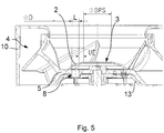
- Figure 4 shows a detailed view of the area of the fan in which the cover plate 2 is arranged.
- the cover disk 2 rests directly on the rotor bell base 13, since the impeller hub 5 in this embodiment only extends as far as the cover disk 2.
- a radial projection 71 on the cover plate 2 covers an area in which the cover plate 2 and the impeller hub 5 abut one another and possibly form a gap.
- the inner surface 30 of the cover plate 2 is spaced apart from the openings 8 as seen in the radial direction.
- the cover plate 2 directly adjoins the openings 8, as shown in FIG Figure 2 is shown.
- the inner surface 30 of the cover disk 2 runs in the radial plane
- the outer surface 31, on the other hand runs in a straight line obliquely radially outwards in the direction of the rotor bell base 13, so that the outer surface 31 of the cover disk 2 merges directly into the impeller hub surface of the impeller hub 5.
- the edge of the central opening 3 is rounded.
- the diameter D of the respective openings 8 and the diameter DPS of the central opening 3 are identified for the exemplary embodiments.
- the cover plate 2 has the overextension section L, which completely overextends the openings 8 in the radial direction.
- the diameter D of the respective openings 8 and the overextension section L are identical.
- the overlapping section UE is provided on the cover disk 2, in which the cover disk 2 extends radially inward beyond the openings 8 and thereby overlaps with the area of the rotor bell base 13 adjoining the openings 8 radially inward.
- the ratio is preferably adjusted in a range between 0.5 and 1.5 as required.
- the diameter DPS of the central opening 3 is greater in both versions than the sum of the overstretching section L and the overlapping section UE.
Landscapes
- Engineering & Computer Science (AREA)
- Mechanical Engineering (AREA)
- General Engineering & Computer Science (AREA)
- Power Engineering (AREA)
- Physics & Mathematics (AREA)
- Thermal Sciences (AREA)
- Structures Of Non-Positive Displacement Pumps (AREA)
- Motor Or Generator Cooling System (AREA)
Applications Claiming Priority (1)
| Application Number | Priority Date | Filing Date | Title |
|---|---|---|---|
| DE102020103772.4A DE102020103772A1 (de) | 2020-02-13 | 2020-02-13 | Ventilator mit Abdeckscheibe an der Rotorglocke |
Publications (3)
| Publication Number | Publication Date |
|---|---|
| EP3865711A1 true EP3865711A1 (fr) | 2021-08-18 |
| EP3865711B1 EP3865711B1 (fr) | 2025-10-22 |
| EP3865711C0 EP3865711C0 (fr) | 2025-10-22 |
Family
ID=74130050
Family Applications (1)
| Application Number | Title | Priority Date | Filing Date |
|---|---|---|---|
| EP21150833.8A Active EP3865711B1 (fr) | 2020-02-13 | 2021-01-11 | Ventilateur pourvu de plaque de recouvrement sur la cloche de rotor |
Country Status (4)
| Country | Link |
|---|---|
| US (1) | US12060887B2 (fr) |
| EP (1) | EP3865711B1 (fr) |
| CN (1) | CN113250982A (fr) |
| DE (1) | DE102020103772A1 (fr) |
Cited By (1)
| Publication number | Priority date | Publication date | Assignee | Title |
|---|---|---|---|---|
| CN114233652A (zh) * | 2021-12-06 | 2022-03-25 | 中国船舶重工集团公司第七0四研究所 | 一种舰船用低噪声高速斜流风机 |
Families Citing this family (2)
| Publication number | Priority date | Publication date | Assignee | Title |
|---|---|---|---|---|
| WO2023023307A1 (fr) | 2021-08-20 | 2023-02-23 | Milwaukee Electric Tool Corporation | Moteur électrique |
| DE102024208270A1 (de) * | 2024-08-30 | 2026-03-05 | Ziehl-Abegg Se | Motor für einen Lüfter, Lüfter und Laufrad |
Citations (5)
| Publication number | Priority date | Publication date | Assignee | Title |
|---|---|---|---|---|
| JPH10210727A (ja) * | 1997-01-17 | 1998-08-07 | Nippon Electric Ind Co Ltd | アウタロータ・ブラシレスモータの冷却用ファン機構 |
| US20020141866A1 (en) * | 2001-03-27 | 2002-10-03 | Wen-Shi Huang | Fan with improved self-cooling capability |
| DE102005006183A1 (de) * | 2005-02-10 | 2006-08-24 | Asia Vital Component Co., Ltd., Hsin-Chuan | Rotor mit zwangsläufiger Kühlung |
| DE102013108506A1 (de) | 2013-08-07 | 2015-02-12 | Ebm-Papst St. Georgen Gmbh & Co. Kg | Außenläufermotor mit einem Radiallüfterrad |
| JP2015139225A (ja) * | 2014-01-20 | 2015-07-30 | 日本電産株式会社 | モータ |
Family Cites Families (12)
| Publication number | Priority date | Publication date | Assignee | Title |
|---|---|---|---|---|
| US5944497A (en) | 1997-11-25 | 1999-08-31 | Siemens Canada Limited | Fan assembly having an air directing member to cool a motor |
| US7616440B2 (en) * | 2004-04-19 | 2009-11-10 | Hewlett-Packard Development Company, L.P. | Fan unit and methods of forming same |
| TWI245483B (en) * | 2004-09-06 | 2005-12-11 | Delta Electronics Inc | Heat-dissipation structure of motor |
| US20070152519A1 (en) * | 2005-12-29 | 2007-07-05 | Minebea Co., Ltd. | Blade and yoke arrangement for cooling stator windings |
| DE102006006702A1 (de) | 2006-02-13 | 2007-08-23 | Asia Vital Component Co., Ltd | Rotor |
| ITBO20070380A1 (it) * | 2007-05-30 | 2008-11-30 | Spal Automotive Srl | Unita' di ventilazione |
| DE102010001354A1 (de) * | 2009-08-26 | 2011-03-03 | Robert Bosch Gmbh | Gebläse |
| DE102010009566A1 (de) * | 2010-02-26 | 2011-09-01 | Ebm-Papst Mulfingen Gmbh & Co. Kg | Radial- oder Diagonal-Ventilatorrad |
| WO2012130404A1 (fr) * | 2011-03-26 | 2012-10-04 | Ebm-Papst St. Georgen Gmbh & Co. Kg | Ventilateur diagonal à refroidissement actif du moteur |
| CN202260790U (zh) * | 2011-09-23 | 2012-05-30 | 宁波菲仕电机技术有限公司 | 一种伺服电机的风冷装置 |
| DE102013215808A1 (de) * | 2013-08-09 | 2015-02-12 | Brose Fahrzeugteile GmbH & Co. Kommanditgesellschaft, Würzburg | Rotornabenanordnung, elektrischer Lüfter |
| JP7105584B2 (ja) * | 2018-03-13 | 2022-07-25 | 山洋電気株式会社 | ファンモータ装置およびファンモータ装置の保護カバー |
-
2020
- 2020-02-13 DE DE102020103772.4A patent/DE102020103772A1/de active Pending
-
2021
- 2021-01-11 EP EP21150833.8A patent/EP3865711B1/fr active Active
- 2021-02-01 CN CN202110137064.6A patent/CN113250982A/zh active Pending
- 2021-02-02 US US17/165,717 patent/US12060887B2/en active Active
Patent Citations (5)
| Publication number | Priority date | Publication date | Assignee | Title |
|---|---|---|---|---|
| JPH10210727A (ja) * | 1997-01-17 | 1998-08-07 | Nippon Electric Ind Co Ltd | アウタロータ・ブラシレスモータの冷却用ファン機構 |
| US20020141866A1 (en) * | 2001-03-27 | 2002-10-03 | Wen-Shi Huang | Fan with improved self-cooling capability |
| DE102005006183A1 (de) * | 2005-02-10 | 2006-08-24 | Asia Vital Component Co., Ltd., Hsin-Chuan | Rotor mit zwangsläufiger Kühlung |
| DE102013108506A1 (de) | 2013-08-07 | 2015-02-12 | Ebm-Papst St. Georgen Gmbh & Co. Kg | Außenläufermotor mit einem Radiallüfterrad |
| JP2015139225A (ja) * | 2014-01-20 | 2015-07-30 | 日本電産株式会社 | モータ |
Cited By (1)
| Publication number | Priority date | Publication date | Assignee | Title |
|---|---|---|---|---|
| CN114233652A (zh) * | 2021-12-06 | 2022-03-25 | 中国船舶重工集团公司第七0四研究所 | 一种舰船用低噪声高速斜流风机 |
Also Published As
| Publication number | Publication date |
|---|---|
| CN113250982A (zh) | 2021-08-13 |
| EP3865711B1 (fr) | 2025-10-22 |
| US20210254634A1 (en) | 2021-08-19 |
| EP3865711C0 (fr) | 2025-10-22 |
| US12060887B2 (en) | 2024-08-13 |
| DE102020103772A1 (de) | 2021-08-19 |
Similar Documents
| Publication | Publication Date | Title |
|---|---|---|
| EP3702620B1 (fr) | Ventilateur axial pourvu d'aubes de roue de ventilateur réduisant le bruit et pourvues de trous | |
| EP3405679B1 (fr) | Ventilateur diagonal | |
| EP3775565B1 (fr) | Ventilateur diagonal compact avec dispositif de guidage aval | |
| EP3865711B1 (fr) | Ventilateur pourvu de plaque de recouvrement sur la cloche de rotor | |
| EP2993357B1 (fr) | Étage de compresseur radial | |
| DE102013109577A1 (de) | Gebläsemodul für einen Wärmetauscher | |
| EP3880967B1 (fr) | Ventilateur diagonal équipé d'un dispositif directeur de sortie | |
| EP2122182B1 (fr) | Roue de ventilateur, système et série de boîte de vitesses | |
| EP2993356A1 (fr) | Étage de compresseur radial | |
| EP4073389A1 (fr) | Roue à aubes pour rotor, et machine électrique | |
| DE202016106538U1 (de) | Diagonalventilator | |
| EP3592987B1 (fr) | Carter semi-hélicoïdal | |
| DE102019101277A1 (de) | Axiallüfteranordnung für Fahrzeuge | |
| DE112018004202T5 (de) | Dampfturbine | |
| EP3608545A1 (fr) | Pompe à vide | |
| DE202018106503U1 (de) | Diagonalventilator mit Nachleiteinrichtung | |
| DE2458014C3 (de) | Stator eines Mehrstufen-Radialverdichters | |
| EP3559473B1 (fr) | Roue à aubes et ventilateur | |
| DE102014224282B4 (de) | Berührungslose Dichtung und Maschinenelementanordnung hiermit | |
| DE102014118210B4 (de) | Mehrflutige Strömungsmaschine | |
| DE102007037012B4 (de) | Gebläseeinheit und handgetragenes Blasgerät | |
| EP4636253A1 (fr) | Ensemble buse d'entrée et turbomachine comprenant une roue porteuse et un ensemble buse d'entrée | |
| EP3683451A1 (fr) | Dispositif de guidage de flux et agencement de ventilateur pourvu de dispositif de guidage de flux | |
| DE202005015357U1 (de) | Lüfter mit einem Lüfterrad | |
| DE10111292A1 (de) | Lüfteranordnung für eine elektrische Maschine |
Legal Events
| Date | Code | Title | Description |
|---|---|---|---|
| PUAI | Public reference made under article 153(3) epc to a published international application that has entered the european phase |
Free format text: ORIGINAL CODE: 0009012 |
|
| STAA | Information on the status of an ep patent application or granted ep patent |
Free format text: STATUS: THE APPLICATION HAS BEEN PUBLISHED |
|
| AK | Designated contracting states |
Kind code of ref document: A1 Designated state(s): AL AT BE BG CH CY CZ DE DK EE ES FI FR GB GR HR HU IE IS IT LI LT LU LV MC MK MT NL NO PL PT RO RS SE SI SK SM TR |
|
| STAA | Information on the status of an ep patent application or granted ep patent |
Free format text: STATUS: REQUEST FOR EXAMINATION WAS MADE |
|
| 17P | Request for examination filed |
Effective date: 20220201 |
|
| RBV | Designated contracting states (corrected) |
Designated state(s): AL AT BE BG CH CY CZ DE DK EE ES FI FR GB GR HR HU IE IS IT LI LT LU LV MC MK MT NL NO PL PT RO RS SE SI SK SM TR |
|
| STAA | Information on the status of an ep patent application or granted ep patent |
Free format text: STATUS: EXAMINATION IS IN PROGRESS |
|
| 17Q | First examination report despatched |
Effective date: 20230622 |
|
| GRAP | Despatch of communication of intention to grant a patent |
Free format text: ORIGINAL CODE: EPIDOSNIGR1 |
|
| STAA | Information on the status of an ep patent application or granted ep patent |
Free format text: STATUS: GRANT OF PATENT IS INTENDED |
|
| INTG | Intention to grant announced |
Effective date: 20250704 |
|
| GRAS | Grant fee paid |
Free format text: ORIGINAL CODE: EPIDOSNIGR3 |
|
| GRAA | (expected) grant |
Free format text: ORIGINAL CODE: 0009210 |
|
| STAA | Information on the status of an ep patent application or granted ep patent |
Free format text: STATUS: THE PATENT HAS BEEN GRANTED |
|
| AK | Designated contracting states |
Kind code of ref document: B1 Designated state(s): AL AT BE BG CH CY CZ DE DK EE ES FI FR GB GR HR HU IE IS IT LI LT LU LV MC MK MT NL NO PL PT RO RS SE SI SK SM TR |
|
| REG | Reference to a national code |
Ref country code: CH Ref legal event code: F10 Free format text: ST27 STATUS EVENT CODE: U-0-0-F10-F00 (AS PROVIDED BY THE NATIONAL OFFICE) Effective date: 20251022 Ref country code: GB Ref legal event code: FG4D Free format text: NOT ENGLISH |
|
| REG | Reference to a national code |
Ref country code: IE Ref legal event code: FG4D Free format text: LANGUAGE OF EP DOCUMENT: GERMAN |
|
| U01 | Request for unitary effect filed |
Effective date: 20251022 |
|
| U07 | Unitary effect registered |
Designated state(s): AT BE BG DE DK EE FI FR IT LT LU LV MT NL PT RO SE SI Effective date: 20251028 |
|
| U20 | Renewal fee for the european patent with unitary effect paid |
Year of fee payment: 6 Effective date: 20260128 |
|
| PG25 | Lapsed in a contracting state [announced via postgrant information from national office to epo] |
Ref country code: ES Free format text: LAPSE BECAUSE OF FAILURE TO SUBMIT A TRANSLATION OF THE DESCRIPTION OR TO PAY THE FEE WITHIN THE PRESCRIBED TIME-LIMIT Effective date: 20251022 |
|
| PG25 | Lapsed in a contracting state [announced via postgrant information from national office to epo] |
Ref country code: NO Free format text: LAPSE BECAUSE OF FAILURE TO SUBMIT A TRANSLATION OF THE DESCRIPTION OR TO PAY THE FEE WITHIN THE PRESCRIBED TIME-LIMIT Effective date: 20260122 |
|
| PG25 | Lapsed in a contracting state [announced via postgrant information from national office to epo] |
Ref country code: HR Free format text: LAPSE BECAUSE OF FAILURE TO SUBMIT A TRANSLATION OF THE DESCRIPTION OR TO PAY THE FEE WITHIN THE PRESCRIBED TIME-LIMIT Effective date: 20251022 |
|
| PG25 | Lapsed in a contracting state [announced via postgrant information from national office to epo] |
Ref country code: RS Free format text: LAPSE BECAUSE OF FAILURE TO SUBMIT A TRANSLATION OF THE DESCRIPTION OR TO PAY THE FEE WITHIN THE PRESCRIBED TIME-LIMIT Effective date: 20260122 |
|
| PG25 | Lapsed in a contracting state [announced via postgrant information from national office to epo] |
Ref country code: IS Free format text: LAPSE BECAUSE OF FAILURE TO SUBMIT A TRANSLATION OF THE DESCRIPTION OR TO PAY THE FEE WITHIN THE PRESCRIBED TIME-LIMIT Effective date: 20260222 |
|
| PG25 | Lapsed in a contracting state [announced via postgrant information from national office to epo] |
Ref country code: PL Free format text: LAPSE BECAUSE OF FAILURE TO SUBMIT A TRANSLATION OF THE DESCRIPTION OR TO PAY THE FEE WITHIN THE PRESCRIBED TIME-LIMIT Effective date: 20251022 |