EP3865715B1 - Réservoir pour une unité de puissance hydraulique modulaire et unité de puissance hydraulique modulaire le comprenant - Google Patents
Réservoir pour une unité de puissance hydraulique modulaire et unité de puissance hydraulique modulaire le comprenant Download PDFInfo
- Publication number
- EP3865715B1 EP3865715B1 EP20157056.1A EP20157056A EP3865715B1 EP 3865715 B1 EP3865715 B1 EP 3865715B1 EP 20157056 A EP20157056 A EP 20157056A EP 3865715 B1 EP3865715 B1 EP 3865715B1
- Authority
- EP
- European Patent Office
- Prior art keywords
- tank
- conduit
- fluid
- opening
- pipe
- Prior art date
- Legal status (The legal status is an assumption and is not a legal conclusion. Google has not performed a legal analysis and makes no representation as to the accuracy of the status listed.)
- Active
Links
Images


Classifications
-
- F—MECHANICAL ENGINEERING; LIGHTING; HEATING; WEAPONS; BLASTING
- F15—FLUID-PRESSURE ACTUATORS; HYDRAULICS OR PNEUMATICS IN GENERAL
- F15B—SYSTEMS ACTING BY MEANS OF FLUIDS IN GENERAL; FLUID-PRESSURE ACTUATORS, e.g. SERVOMOTORS; DETAILS OF FLUID-PRESSURE SYSTEMS, NOT OTHERWISE PROVIDED FOR
- F15B21/00—Common features of fluid actuator systems; Fluid-pressure actuator systems or details thereof, not covered by any other group of this subclass
- F15B21/04—Special measures taken in connection with the properties of the fluid
- F15B21/044—Removal or measurement of undissolved gas, e.g. de-aeration, venting or bleeding
-
- F—MECHANICAL ENGINEERING; LIGHTING; HEATING; WEAPONS; BLASTING
- F15—FLUID-PRESSURE ACTUATORS; HYDRAULICS OR PNEUMATICS IN GENERAL
- F15B—SYSTEMS ACTING BY MEANS OF FLUIDS IN GENERAL; FLUID-PRESSURE ACTUATORS, e.g. SERVOMOTORS; DETAILS OF FLUID-PRESSURE SYSTEMS, NOT OTHERWISE PROVIDED FOR
- F15B1/00—Installations or systems with accumulators; Supply reservoir or sump assemblies
- F15B1/26—Supply reservoir or sump assemblies
-
- F—MECHANICAL ENGINEERING; LIGHTING; HEATING; WEAPONS; BLASTING
- F15—FLUID-PRESSURE ACTUATORS; HYDRAULICS OR PNEUMATICS IN GENERAL
- F15B—SYSTEMS ACTING BY MEANS OF FLUIDS IN GENERAL; FLUID-PRESSURE ACTUATORS, e.g. SERVOMOTORS; DETAILS OF FLUID-PRESSURE SYSTEMS, NOT OTHERWISE PROVIDED FOR
- F15B13/00—Details of servomotor systems ; Valves for servomotor systems
- F15B13/02—Fluid distribution or supply devices characterised by their adaptation to the control of servomotors
-
- F—MECHANICAL ENGINEERING; LIGHTING; HEATING; WEAPONS; BLASTING
- F15—FLUID-PRESSURE ACTUATORS; HYDRAULICS OR PNEUMATICS IN GENERAL
- F15B—SYSTEMS ACTING BY MEANS OF FLUIDS IN GENERAL; FLUID-PRESSURE ACTUATORS, e.g. SERVOMOTORS; DETAILS OF FLUID-PRESSURE SYSTEMS, NOT OTHERWISE PROVIDED FOR
- F15B21/00—Common features of fluid actuator systems; Fluid-pressure actuator systems or details thereof, not covered by any other group of this subclass
- F15B21/04—Special measures taken in connection with the properties of the fluid
- F15B21/041—Removal or measurement of solid or liquid contamination, e.g. filtering
-
- F—MECHANICAL ENGINEERING; LIGHTING; HEATING; WEAPONS; BLASTING
- F15—FLUID-PRESSURE ACTUATORS; HYDRAULICS OR PNEUMATICS IN GENERAL
- F15B—SYSTEMS ACTING BY MEANS OF FLUIDS IN GENERAL; FLUID-PRESSURE ACTUATORS, e.g. SERVOMOTORS; DETAILS OF FLUID-PRESSURE SYSTEMS, NOT OTHERWISE PROVIDED FOR
- F15B21/00—Common features of fluid actuator systems; Fluid-pressure actuator systems or details thereof, not covered by any other group of this subclass
- F15B21/04—Special measures taken in connection with the properties of the fluid
- F15B21/042—Controlling the temperature of the fluid
- F15B21/0423—Cooling
-
- F—MECHANICAL ENGINEERING; LIGHTING; HEATING; WEAPONS; BLASTING
- F15—FLUID-PRESSURE ACTUATORS; HYDRAULICS OR PNEUMATICS IN GENERAL
- F15B—SYSTEMS ACTING BY MEANS OF FLUIDS IN GENERAL; FLUID-PRESSURE ACTUATORS, e.g. SERVOMOTORS; DETAILS OF FLUID-PRESSURE SYSTEMS, NOT OTHERWISE PROVIDED FOR
- F15B2211/00—Circuits for servomotor systems
- F15B2211/20—Fluid pressure source, e.g. accumulator or variable axial piston pump
- F15B2211/205—Systems with pumps
- F15B2211/20576—Systems with pumps with multiple pumps
-
- F—MECHANICAL ENGINEERING; LIGHTING; HEATING; WEAPONS; BLASTING
- F15—FLUID-PRESSURE ACTUATORS; HYDRAULICS OR PNEUMATICS IN GENERAL
- F15B—SYSTEMS ACTING BY MEANS OF FLUIDS IN GENERAL; FLUID-PRESSURE ACTUATORS, e.g. SERVOMOTORS; DETAILS OF FLUID-PRESSURE SYSTEMS, NOT OTHERWISE PROVIDED FOR
- F15B2211/00—Circuits for servomotor systems
- F15B2211/60—Circuit components or control therefor
- F15B2211/61—Secondary circuits
- F15B2211/611—Diverting circuits, e.g. for cooling or filtering
-
- F—MECHANICAL ENGINEERING; LIGHTING; HEATING; WEAPONS; BLASTING
- F15—FLUID-PRESSURE ACTUATORS; HYDRAULICS OR PNEUMATICS IN GENERAL
- F15B—SYSTEMS ACTING BY MEANS OF FLUIDS IN GENERAL; FLUID-PRESSURE ACTUATORS, e.g. SERVOMOTORS; DETAILS OF FLUID-PRESSURE SYSTEMS, NOT OTHERWISE PROVIDED FOR
- F15B2211/00—Circuits for servomotor systems
- F15B2211/60—Circuit components or control therefor
- F15B2211/615—Filtering means
-
- F—MECHANICAL ENGINEERING; LIGHTING; HEATING; WEAPONS; BLASTING
- F15—FLUID-PRESSURE ACTUATORS; HYDRAULICS OR PNEUMATICS IN GENERAL
- F15B—SYSTEMS ACTING BY MEANS OF FLUIDS IN GENERAL; FLUID-PRESSURE ACTUATORS, e.g. SERVOMOTORS; DETAILS OF FLUID-PRESSURE SYSTEMS, NOT OTHERWISE PROVIDED FOR
- F15B2211/00—Circuits for servomotor systems
- F15B2211/60—Circuit components or control therefor
- F15B2211/62—Cooling or heating means
Definitions
- the present invention relates to the technical field of tanks for a modular hydraulic power unit. Furthermore, the present invention relates to the technical fields of modular hydraulic power units comprising such tanks.
- hydraulic power unit assemblies with an installed power ranging from 350 to 6000kW can be delivered to the market faster, while at the same time meeting a high quality standard.
- tanks for Large Hydraulic Power Units should be optimized in floor space, amount of connections and flow.
- WO 2011/149949 A2 discloses a fluid storage tank for removing entrained air from fluid stored within and passing through the fluid storage tank.
- the problem to be solved is thus the realization of a tank for a modular hydraulic power unit, which at the same time enables the realization of a compact modular hydraulic power unit and also effectively enables to reduce the amount of air dissolved in the fluid, like oil, which is contained in the tank.
- the problem to be solved is how to create a standard tank with minimal variants and with a scaling capacity from 2500 I up to 30000 or more I with limited floor space and flow optimized micro intelligence.
- the present invention is based on the idea of deflecting the flow of fluid at the inside of the tanks so as to create an ascending-descending flow, which enables to effectively reduce the amount of air dissolved in the fluid, while at the same time an effective compactness of the tank of the modular hydraulic power unit is maintained.
- tank is used to describe a volume configured to store an amount of liquid, like oil. Therefore, in this invention the term “tank” is a synonym of reservoir.
- inclined surface it is meant that the surface has a leaning or slope.
- a plain surface having a constant inclination angle and a curvature having an inclined angle, which varies with the position are meant.
- prism it is meant a solid with bases that are polygons and the sides are flat surfaces. Therefore, even a cylinder falls in said definition since a cylinder is a prism with an infinite number of faces.
- a tank for a modular hydraulic power unit for the supply of a pressurized fluid wherein said tank extending primarily along a vertical direction; said tank being provided with a first opening which is positioned at an upper portion of said tank and through which a fluid can be introduced into said tank; said tank further comprising a conduit having a first and a second end portion, wherein said first end portion is attached to said first opening and wherein said second end portion is positioned at a central portion of said tank so as to convey said fluid coming from said first opening to a central portion of said tank; wherein said second end portion of said conduit is configured so as to release the fluid coming from said first opening along a direction substantially perpendicular to said vertical direction of said tank; wherein said tank comprises at least one inclined surfaces, which faces said second end portion of said conduit and which is inclined with respect to said vertical direction of said tank so as to deflect the flow of fluid coming from said second end portion of said conduit toward an upper portion of said tank.
- This embodiment enables to deflect the flow of fluid at the inside of the tanks so as to create an ascending-descending flow, which enables to effectively increase the length of the oil flow path inside the tank, and to obtain a high oil flow path even with a small volume of the tank. In that way it is effectively possible to reduce the amount of air dissolved in the fluid, while at the same time an effective compactness of the tank of the modular hydraulic power unit is maintained.
- inclined surface both a constant slope and a continuous/discontinuous varying slope are covered.
- a distance between said first opening and said central portion measured along an axis parallel to said vertical direction is at least 1/2 of a vertical extension of said tank, preferably greater than 3/5 of the vertical extension of said tank, more preferably greater than 2/3 of the vertical extension of said tank, more preferably greater than 4/5 of the vertical extension of said tank. Said embodiment enables to use the vertical extension of the tank to effectively increase the oil flow path.
- said conduit extends along said vertical direction of said tank. Said feature enables to obtain a symmetrical tank since the conduit can be preferably positioned along the axis of said tank.
- said tank comprises two of said inclined surfaces, which are provided on opposite sides of said tank.
- an element for example a diffusor, which comprises an inlet and two outlet sections, which are positioned on opposite sides in order to face each of said inclined walls, in order to effectively use the all volume of the tank for the internal flow path of oil.
- said conduit comprises a diffusor which is positioned at said second end portion and is configured to change a direction of the fluid coming from said first end portion so as to introduce said fluid into said tank along a direction substantially perpendicular to said vertical direction of said tank.
- a tilt angle of said at least one inclined surface with respect to said vertical direction of said tank is comprised between 20° and 45°, preferably between 22° and 35°, still more preferably equal to 25°.
- a lower portion of said tank which is positioned below, preferably directly below, said inclined surface is substantially a lower prism, wherein said lower prism is elongated along said vertical direction, wherein at least one side of said lower prism is provided with a second opening, wherein connecting means are provided at said second opening so as to protrude externally to said tank, wherein said connecting means are configured to enable the fluid connection of the internal volume of said tank with another tank having analogous characteristics.
- said second opening is provided on a lateral side of said lower prism at which said inclined surface is provided. Said feature effectively enables to effectively reduce the dimensions of the HPU since the tanks can be installed next to each other without a large distance between these.
- said lower prism is provided with two of said second opening, which are provided on opposite sides of said lower prism.
- said inclined surface is a lateral wall of said tank. Said characteristic is very advantageous since it effectively enables to use a lateral wall of the tank in order to deflect the flow and no additional element is required.
- an upper portion, which is preferably directly above said inclined lateral wall, of said tank is substantially an upper prism, wherein the upper prism is elongated along said vertical direction and wherein the conduit extends preferably along a central axis of said upper prism, wherein said at least one inclined lateral wall is positioned at a lower portion of said upper prism so as to reduce a section of said tank taken along a plane which is perpendicular to said vertical direction.
- a modular hydraulic power unit for the supply of a pressurized fluid comprising a plurality of tanks according to the invention connected with each other is provided, wherein each of the tank is provided with a third opening, which is provided at a lower portion of said tank, wherein a pump is provided at said third opening so as to supply the fluid contained in said tank in form of pressurized fluid to an external user.
- the third opening is positioned on a wall of the tank on which no lateral inclined walls are provided.
- a first and a second pipe are provided into said second opening so as to pass through said tanks, wherein each of the pipe is provided with a plurality of holes so as to enable a fluid to pass therethrough.
- said first and said second pipe comprises a plurality of sub-pipes positioned next to each other and wherein an end portion of a sub-pipe is preferably in direct contact with an end portion of another sub-pipe.
- said modular hydraulic power unit further comprises a filtering and/or cooling system for filtering and/or cooling the fluid passing therethrough, wherein said first pipe is connected to an inlet of said filtering and/or cooling system so as to provide fluid coming from said tanks and flowing through said plurality of holes of said first pipe to said filtering and/or cooling system and wherein said second pipe is connected to an outlet of said filtering and/or cooling system so as to reintroduce the cooled and/or filtered fluid into each of the tanks through said plurality of holes of said second pipe.
- a filtering and/or cooling system for filtering and/or cooling the fluid passing therethrough
- said modular hydraulic power unit further comprises an input/output interface which is connected to one of the connecting means of a tank, wherein said input/output interface has a substantially hollow cylindrical shape main body closed at the end portions thereof and having two conduits which extends parallel to an axis of the main body, wherein said two conduits of said input/output interface provides two openings on a base of the main body which faces said connecting means of said tank, wherein said two conduits comprise an inlet and an outlet conduit, wherein said inlet conduit is directly connected with said first pipe and wherein said outlet conduit is directly connected with said second pipe, wherein said input/output interface further comprises dividing means which divides the internal volume of the hollow main body of said input/output interface into a first and a second chamber, wherein said inlet conduit is provided with openings so as to be fluidically in contact with said first chamber, wherein said outlet conduit is provided with openings so as to be fluidically in contact with said second chamber.
- said filtering and/or cooling system is configured to create and overpressure in said second chamber and an underpressure in said firs chamber. In that way it is effectively possible to provide an internal circulation flow of oil, in order to filter and/or cool the oil contained in the tanks.
- said first chamber is positioned between said second chamber and said connecting means of said tank and wherein said modular hydraulic power unit is preferably further provided with a pump for sucking fluid from said first chamber and for conveying said fluid through said filtering and/or cooling system.
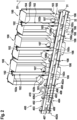
- Figure 1 shows a three dimensional view of a modular hydraulic power unit 1000 (from now on simply called modular HPU or only HPU).
- the modular HPU is configured to supply a compressed fluid, normally oil, to a user and to receive the expanded oil again, after said fluid has been used by the user for any scope.
- the HPU 1000 comprises a plurality of tanks 100 connected with each other and which are connected with a set of pumps (which will be shown with more details in the following figures).
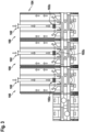
- Figure 2 shows a three-dimensional frontal cross section taken along a plane x-z of Figure 1 .
- figure 2 shows three tanks 100 connected in series according to a preferred embodiment of the present invention.
- Each of the tanks 100 extends primarily along a vertical direction D1 (which coincides with the z direction of figure 1 ).
- Each of the tanks 100 is provided with a first opening 101 which is positioned at an upper portion of the tank 100 and through which, as will be clearer with the prosecution of the disclosure, oil can be introduced into the tank 100.
- the first opening 101 is positioned on a top surface of the tank 100.
- said feature is not essential for this invention.
- the first opening 100 could also be positioned on a lateral upper portion of the tank 100.
- a conduit 102 extends from the first opening 101 to a central portion of the tank 100.
- the conduit 102 is a straight conduit extending along the axis of the tank 100, which is parallel to the vertical direction D1. Therefore, the conduit 102 comprises a first end portion 102a, which is positioned at said first opening, and a second end portion 102b, which is positioned at a central portion of the tank 100.
- central portion it is meant an internal portion of the tank 102 which has a significant distance from the external walls of the tank 102.
- a distance between the first opening 101 and the central portion of the tank 100 where the second end portion 102b is positioned, measured along an axis parallel to the vertical direction D1, is at least 1/2 of a vertical extension of the tank 100, preferably greater than 2/3 of the vertical extension of the tank 100.
- the conduit 102 at its second end portion 102b comprises a diffusor 102c, which is configured to change the direction of the flow of oil coming from the first opening 101 between a substantially vertical direction (upstream of the diffusor 102c) to a substantially horizontal direction, which is substantially perpendicular to the vertical direction D1 of the tank 100 (downstream of the diffusor 102c).
- the form of the diffusor 102c is not restricted to a particular form and could also be replaced by a curvature of the conduit 102, which would reach the same scope.
- the tank 100 comprises two inclined walls 103, which face the second end portion 102a of the conduit 102 and which are inclined with respect to the vertical direction D1 of the tank 100 so as to deflect the flow of oil coming from the second end portion 102b of the conduit 102 toward an upper portion of the tank 100.
- the two inclined surfaces 103 are provided on opposite sides of the tank 100.
- a tilt angle of the inclined walls 103 of the tank 100 with respect to the vertical direction D1 of the tank is comprised between 20° and 45°, preferably between 22° and 35°, still more preferably equal to 25°
- An upper portion 104 of the tank 100, which is directly above the inclined lateral walls 103 of the tank 100, is substantially an upper prism, for example an upper rectangular prism or a cylinder.
- the prism 104 is elongated along the vertical direction D1 and the inclined lateral walls are positioned on two opposite sides of the lower portion of the prism 104 so as to reduce a section of the tank 100 taken along a plane which is perpendicular to the vertical direction D1.
- a lower portion 105 of the tank 100 which is positioned directly below the inclined lateral walls 103, is substantially a lower prism, for example a lower rectangular prism or a cylinder.
- the prism 105 is elongated along the vertical direction D1.
- One side of the lower prism 105 is provided with two second openings 106, which are positioned on two opposite sides of the lower prism 105, which correspond to the sides on which the inclined lateral walls 103 are provided.
- Connecting means 108 are provided at the two second openings 106 so as to protrude externally to the tank 100.
- the connecting means 108 comprises a tubular portion 108a positioned at the second openings 106 and a flange portion 108b, which is positioned at a distal end portion of the connecting means 108 with respect to the two second openings 106.
- each tank 100 are connected with connecting means 108 of another tank 108, by means of the flange portions 108b thereof and, as will be clearer explained in the prosecution of the disclosure, are configured to enable the fluid connection of the internal volume of each of the tanks 100 with the other tanks 100, in order to maintain the same level of oil inside the tank 100.
- the connecting means 108 of the tanks 100 positioned on the left-hand side and on the right-hand side of figure 2 have a different function and in some cases could be also omitted.
- the connecting means 108 on the left hand side of figure 2 are connected with a cooling and/or filtering system.
- the connecting means 108 can be represented by widely known large flanges, whose pattern is assigned according to DIN EN 1092-1, by circular flanges for pipes, valves, fittings and accessories.
- the tank 100 is provided with two third openings 107, which are positioned one above the other, and which are normally used for connecting the tank with one or more pumps 81, 82 (shown in figure 5 ) for the supply of pressurized oil to an external user.
- a first pipe 30 and a second pipe 31 pass through the second openings 107 of the tank 100 and the connecting means 108.
- Each of the pipe is provided with a plurality of holes, which enable a fluid connection of the internal portion of the pipes with the oil contained in the tank 100.
- the conduit 102 is attached to a lateral surface of the first pipe 31, so as to stabilize and to reduce oscillations of the conduit 102.
- the conduit 102 at a portion lower than the diffusor 102c is closed. Therefore, even if the conduit 102 seems to extend to the first pipe 31, the portion comprised between the diffusor 102 and the first pipe 31 is closed, so that the all amount of oil coming from the pipe 102 is caused to flow directly through the diffusor 102c.
- These pipes 30, 31 can be used to convey the fluid contained in the tank 100 to a filtering and/or cooling system 50 and to convey the fluid back to the tanks.
- the first and the second pipes 31, 32 are preferably composed by a plurality of sub-pipes, each extending between the two connecting means 108 of each tank 100.
- This solution enables to facilitate the transport and installation of the components of the HPU 1000 since no transportation and installation of long external pipes is requested. External leakage points are herewith minimalized. Additionally, due to the low overpressure and underpressure in the first and the second pipes 31, 32 (which will be described more in details in the prosecution of the description) and due to the specific closed configuration of the HPU (the connection of the sub-pipes surrounded by oil of the tank 100), there is no necessity to provide sealing means between the end portions of the sub-pipes. In that way an easy connection of the sub-pipes and therefore of the tanks is effectively reached.
- the connecting means 108 are positioned at the left-hand side and are connected to an input/output interface 400, which is configured to connect the connecting means of the tank 100 with the filtering and/or cooling system 50.
- the input/output interface 400 has a substantially hollow cylindrical shape main body 401 closed at the end portions 402a, 402b thereof and having two conduits 403, 404, which extends parallel to the axis of the main body 401.
- the two conduits 403, 404 of the input/output interface 400 provides two openings on the first end portion 402a of the main body 401, which faces the connecting means 108 of the tank 100.
- the two conduits 403, 404 comprise an inlet conduit 403 and an outlet conduit 404, wherein the inlet conduit 403 is directly connected with the first pipe 30 and wherein the outlet conduit 401 is directly connected with the second pipe 31,
- the input/output interface 400 further comprises dividing means 405, which divides the internal volume of the hollow volume of the input/output interface 400 into a first chamber 406 and a second chamber 407.
- the dividing means 405 is represented by a plate having two holes, which enable the inlet and outlet conduit to pass therethrough and at the same time to maintain a sealing between the first and the second chamber 406, 407.
- the inlet conduit 403 is provided with openings 408, so as to be fluidically in contact with the first chamber 406. Furthermore, the outlet conduit 404 is provided also with openings 409 so as to be fluidically in contact with the second chamber 407.
- both the openings 408 and 409 of the inlet and outlet conduit respectively are two, which extends along an axial direction of the conduit.
- the first chamber 406 is positioned between the second chamber 407 and the connecting means 108 of the tank 100.
- the first chamber 406 is provided with a lateral opening 406a, which enables to fluidically connect the first chamber with the filtering and/or cooling system 50 described above. Therefore, the first chamber 406 has the function of an oil supply means for the filtering and/or cooling system 50.
- the opening 406a of the first chamber 406 is provided with connecting means 410, which protrudes outwards from the first chamber 406 and are attached to a pump (not shown) for sucking fluid from the first chamber 406 through the opening 406a and to convey the fluid through the filtering and/or cooling system 50.
- the second chamber 407 has the function of collecting oil coming from the filtering and/or cooling system 50 and to deliver said oil to the outlet conduit 404.
- first and the second chamber 406 and 407 also for another block of tanks 100, which are positioned on the left-hand side of figure 2 . In this way, the oil will reach the first chamber 406 both from the left and from the right hand side of figure 2 .
- the return oil coming from an external user, is introduced into the modular HPU 1000 through the first opening 101.
- the oil flows from the top of the tank 100 along the vertical direction D1 through the conduit 102.
- the return oil is introduced inside of the tank 100 by means of the diffusor 102c, which is positioned at the second end portion 102b of the conduit 102.
- This diffusor 102c faces the inclined lateral walls 103 and is configured to release the oil flow along a direction substantially perpendicular to the vertical direction D1. This will result in a deflection of the oil flow inside the tank 100.
- the oil is deflected from a direction substantially perpendicular to the vertical direction D1 to a direction substantially parallel to the vertical direction D1. In that way the oil is returned toward an upper portion of the tank 100 (see the arrows in the figure).
- the upwards flow of the return oil effectively decreases the amount of air in the oil, and, therefore, effectively provides a degassing process of the oil.
- the oil, which is highly degassed as it has reached the top portion of the tank 100 will flow from topside to the bottom of the tank 100 where it will flow, due to a slight vacuum pressure, in the first pipe 31 through the holes of the first pipe 31.
- the slight vacuum pressure is due to a pump (not shown), which is attached at the opening 406a of the first chamber 406. Said pump is normally driven by an electromotor.
- the filtering and/or cooling system 50 comprises a low pressure pump with electromotor, a low pressure and high volume filter.
- first and the second chambers 406 and 407 are used as first and the second chambers 406 and 407 for another block of tanks 100, which are positioned on the left-hand side of figure 3 .
- the oil will reach the first chamber both from the left and from the right hand side of figure 3 , as shown by the arrows. Additionally, the oil will be conveyed both toward the right and to the left of the second chamber 407.
- the cooled and/or filtered oil is reintroduced in each of the tanks 100 passing through the second chamber 407 by means of the second pipe 32, and in particular through the holes of the second pipe 32.
- the flowing of the oil through the second pipe 32 is guaranteed by a slight overpressure provided on the oil by means of the pump described above, which is positioned upstream of the filtering and/or cooling system 50.
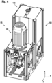
- FIG 4 shows in details a three dimensional external view of a single tank 100 in a modular hydraulic power unit 1000.
- the tank 100 as can be more clearly seen in the three-dimensional cross section of figure 5 , is provided with a pumping system 80 comprising two pumps 81, 82 driven by an electric motor 83, which are positioned at the third openings 107 of the tank 100.
- the two pumps 81, 82 are positioned one above the other, and are configured to supply pressurized oil to an external user.
- a leakage channel 84 connects a leakage port of the pumps with the first pipe 31.
- the pumps 81, 82 are connected to the third openings (107) by means of straight horizontal tubes 85 and a flange portion 86, which is attached to said third openings 107.
- the flange portion 107 has a particular form, which is eccentric. In that way, it is possible to install any type of pump 81, 82 and to adapt the system to the dimension of the particular dimensions of the pumps chosen by means of an eccentric flange, as the one described in the present invention.
- conduit 102 has been described to be parallel to the vertical direction D1 of the tank 100, said conduit could have a different shape, which substantially enable to provide oil coming from the first opening 101 to a lower portion of the tank 100.
- the tank 100 has been described to comprise at least one inclined lateral wall for deflecting the flow of oil coming from the second end portion 102a of the conduit 102, it is also possible to substitute the described inclined lateral wall of the tank 100 with one or more additional inclined surfaces, which are fixed to the tank and which face he second end portion 102a of the conduit 102 and are inclined with respect to the vertical direction D1 of the tank 100, in order to reach the same scope of the inclined lateral walls of the tank 100.
- figure 2 shows three tanks 100 connected in series it is possible to increase or decrease the number of tanks in series connected with each other.
- the tank 100 is provided with two third openings 107, which are positioned one above the other, it is possible also to provide the third openings on two opposite sides of the tank or one next to the other. Another possibility is also represented by providing the tank 100 with only one third opening 107 or with a higher number of third openings 107.
Landscapes
- Engineering & Computer Science (AREA)
- Physics & Mathematics (AREA)
- Fluid Mechanics (AREA)
- Mechanical Engineering (AREA)
- General Engineering & Computer Science (AREA)
- Chemical & Material Sciences (AREA)
- Analytical Chemistry (AREA)
- Supply Devices, Intensifiers, Converters, And Telemotors (AREA)
Claims (15)
- Réservoir (100) pour une unité de puissance hydraulique modulaire (1000) pour l'alimentation d'un fluide sous pression ; ledit réservoir (100) s'étendant principalement dans une direction verticale (D1) ;ledit réservoir (100) étant muni d'une première ouverture (101) qui est positionnée au niveau d'une partie supérieure dudit réservoir (100) et à travers laquelle un fluide peut être introduit dans ledit réservoir (100) ;ledit réservoir (100) comprenant en outre un conduit (102) ayant une première et une seconde partie d'extrémité (102a, 102b), dans lequel ladite première partie d'extrémité (102a) est fixée à ladite première ouverture (101) et dans lequel ladite seconde partie d'extrémité (102b) est positionnée au niveau d'une partie centrale dudit réservoir (100) de façon à transporter ledit fluide provenant de ladite première ouverture (101) vers une partie centrale dudit réservoir (100) ;dans lequel ladite seconde partie d'extrémité (102b) dudit conduit (102) est conçue de façon à libérer le fluide provenant de ladite première ouverture (101) dans une direction sensiblement perpendiculaire à ladite direction verticale (D1) dudit réservoir (100) ;dans lequel ledit réservoir (100) comprend au moins une surface inclinée (103), qui fait face à ladite seconde partie d'extrémité (102b) dudit conduit (102) et qui est inclinée par rapport à ladite direction verticale (D1) dudit réservoir (100) de façon à dévier l'écoulement de fluide provenant de ladite seconde partie d'extrémité dudit conduit (102) en direction d'une partie supérieure dudit réservoir (100), dans lequel une partie inférieure (105) dudit réservoir, qui est positionnée sous, de préférence directement en dessous, de ladite surface inclinée (103) est sensiblement un prisme inférieur, dans lequel ledit prisme inférieur est allongé dans ladite direction verticale (D1), dans lequel au moins un côté dudit prisme inférieur est muni d'une deuxième ouverture (106), dans lequel des moyens de liaison (108) sont placés au niveau de ladite deuxième ouverture (106) de façon à faire saillie à l'extérieur dudit réservoir (100), dans lequel lesdits moyens de liaison (108) sont conçus pour permettre la liaison fluidique du volume interne dudit réservoir (100) avec un autre réservoir (100) présentant des caractéristiques analogues.
- Réservoir (100) selon la revendication 1, dans lequel une distance entre ladite première ouverture (101) et ladite partie centrale mesurée le long d'un axe parallèle à ladite direction verticale (D1) est égale à au moins la moitié d'une extension verticale dudit réservoir (100), de préférence est supérieure aux deux tiers de l'extension verticale dudit réservoir (100).
- Réservoir (100) selon l'une quelconque des revendications 1 ou 2, dans lequel ledit conduit (102) s'étend dans ladite direction verticale (D1) dudit réservoir (100).
- Réservoir (100) selon l'une quelconque des revendications 1 à 3, dans lequel ledit réservoir (100) comprend deux desdites surfaces inclinées (103), qui sont placées sur des côtés opposés dudit réservoir (100).
- Réservoir (100) selon l'une quelconque des revendications 1 à 4, dans lequel ledit conduit (102) comprend un diffuseur (102c) qui est positionné au niveau de ladite seconde partie d'extrémité (102b) et est conçu pour modifier une direction du fluide provenant de ladite première partie d'extrémité (102a) de façon à introduire le fluide dans ledit réservoir (100) dans une direction sensiblement perpendiculaire à ladite direction verticale (D1) dudit réservoir (100).
- Réservoir (100) selon la revendication 1, dans lequel ladite deuxième ouverture (106) est placée sur un côté latéral dudit prisme inférieur (105) sur lequel ladite surface inclinée (103) est placée.
- Réservoir (100) selon la revendication 1, dans lequel ledit prisme inférieur (105) est muni de deux desdites secondes ouvertures (106), qui sont placées sur des côtés opposés dudit prisme inférieur (105).
- Réservoir (100) selon l'une quelconque des revendications 1 à 6, dans lequel ladite surface inclinée (103) est une paroi latérale dudit réservoir (100).
- Réservoir (100) selon la revendication 8, dans lequel une partie supérieure (104), qui est de préférence placée directement au-dessus de ladite paroi latérale inclinée (103) dudit réservoir (100), est sensiblement un prisme supérieur, dans lequel le prisme supérieur est allongé dans ladite direction verticale (D1) et dans lequel le conduit (102) s'étend de préférence le long d'un axe central dudit prisme supérieur, dans lequel ladite au moins une paroi latérale inclinée (103) est positionnée au niveau d'une partie inférieure dudit prisme supérieur de façon à réduire une section dudit réservoir (100) prise dans un plan qui est perpendiculaire à ladite direction verticale (D1).
- Unité de puissance hydraulique modulaire (1000) pour l'alimentation d'un fluide sous pression, comprenant une pluralité de réservoirs (100) selon l'une quelconque des revendications 1 à 9 reliés les uns aux autres, dans laquelle chacun des réservoirs (100) est muni d'une troisième ouverture (107), qui est placée au niveau d'une partie inférieure (105) dudit réservoir (100), dans laquelle une pompe (81, 82) est placée au niveau de ladite troisième ouverture (107) de façon à fournir le fluide contenu dans ledit réservoir (100) sous la forme de fluide sous pression à un utilisateur externe.
- Unité de puissance hydraulique modulaire (1000) selon la revendication 10 lorsqu'elle dépend de la revendication 6, dans laquelle un premier et un second tuyau (31, 32) sont placés dans ladite deuxième ouverture (106) de façon à passer à travers lesdits réservoirs (100), dans laquelle chacun des tuyaux (31, 32) est muni d'une pluralité de trous de façon à permettre le passage d'un fluide à travers.
- Unité de puissance hydraulique modulaire (1000) selon la revendication 11, dans laquelle lesdits premier et second tuyaux (31, 32) comprennent une pluralité de sous-tuyaux positionnés à côté les uns des autres et dans laquelle une partie d'extrémité d'un sous-tuyau est de préférence en contact direct avec une partie d'extrémité d'un autre sous-tuyau.
- Unité de puissance hydraulique modulaire (1000) selon l'une quelconque des revendications 11 ou 12, comprenant en outre un système de filtrage et/ou de refroidissement (50) destiné à filtrer et/ou refroidir le fluide passant à travers, dans laquelle ledit premier tuyau (31) est relié à une entrée dudit système de filtrage et/ou de refroidissement de façon à fournir le fluide provenant desdits réservoirs (100) et circulant à travers ladite pluralité de trous dudit premier tuyau (31) audit système de filtrage et/ou de refroidissement (50) et dans laquelle ledit second tuyau (32) est relié à une sortie dudit système de filtrage et/ou de refroidissement (50) de façon à réintroduire le fluide refroidi et/ou filtré dans chacun des réservoirs (100) par l'intermédiaire de ladite pluralité de trous dudit second tuyau (32).
- Unité de puissance hydraulique modulaire (1000) selon la revendication 13,dans laquelle ladite unité de puissance hydraulique modulaire (1000) comprend en outre une interface d'entrée/sortie (400) qui est reliée à l'un des moyens de liaison (108) d'un réservoir (100), dans laquelle ladite interface d'entrée/sortie (400) possède un corps principal de forme cylindrique sensiblement creux (401) fermé au niveau de ses parties d'extrémité (402a, 402b) et ayant deux conduits (403, 404) qui s'étendent parallèlement à un axe du corps principal,dans laquelle lesdits deux conduits (403, 404) de ladite interface d'entrée/sortie (400) fournissent deux ouvertures sur une base du corps principal (401) qui fait face auxdits moyens de liaison (108) dudit réservoir (100),dans laquelle lesdits deux conduits (403, 404) comprennent un conduit d'entrée et un conduit de sortie (403, 404), dans laquelle ledit conduit d'entrée (403) est directement relié audit premier tuyau (31) et dans laquelle ledit conduit de sortie (404) est directement relié audit second tuyau (32),dans laquelle ladite interface d'entrée/sortie (400) comprend en outre des moyens de division (405) qui divisent le volume interne du corps principal creux (401) de ladite interface d'entrée/sortie (400) en une première et une seconde chambre (406, 407),dans laquelle ledit conduit d'entrée (403) est muni d'ouvertures (408) de façon à être en contact fluidique avec ladite première chambre (406) ;dans laquelle ledit conduit de sortie (404) est muni d'ouvertures (409) de façon à être en contact fluidique avec ladite seconde chambre (407).
- Unité de puissance hydraulique modulaire (1000) selon la revendication 14, dans laquelle ledit système de filtrage et/ou de refroidissement (50) est conçu pour créer une surpression dans ladite seconde chambre (407) et une sous-pression dans ladite première chambre (406).
Priority Applications (3)
| Application Number | Priority Date | Filing Date | Title |
|---|---|---|---|
| ES20157056T ES2973102T3 (es) | 2020-02-13 | 2020-02-13 | Tanque para una unidad de potencia hidráulica modular y unidad de potencia hidráulica modular que comprende el mismo |
| EP20157056.1A EP3865715B1 (fr) | 2020-02-13 | 2020-02-13 | Réservoir pour une unité de puissance hydraulique modulaire et unité de puissance hydraulique modulaire le comprenant |
| CN202110181833.2A CN113251009A (zh) | 2020-02-13 | 2021-02-10 | 模块化液压动力单元的罐和包括罐的模块化液压动力单元 |
Applications Claiming Priority (1)
| Application Number | Priority Date | Filing Date | Title |
|---|---|---|---|
| EP20157056.1A EP3865715B1 (fr) | 2020-02-13 | 2020-02-13 | Réservoir pour une unité de puissance hydraulique modulaire et unité de puissance hydraulique modulaire le comprenant |
Publications (2)
| Publication Number | Publication Date |
|---|---|
| EP3865715A1 EP3865715A1 (fr) | 2021-08-18 |
| EP3865715B1 true EP3865715B1 (fr) | 2023-12-13 |
Family
ID=69581986
Family Applications (1)
| Application Number | Title | Priority Date | Filing Date |
|---|---|---|---|
| EP20157056.1A Active EP3865715B1 (fr) | 2020-02-13 | 2020-02-13 | Réservoir pour une unité de puissance hydraulique modulaire et unité de puissance hydraulique modulaire le comprenant |
Country Status (3)
| Country | Link |
|---|---|
| EP (1) | EP3865715B1 (fr) |
| CN (1) | CN113251009A (fr) |
| ES (1) | ES2973102T3 (fr) |
Family Cites Families (8)
| Publication number | Priority date | Publication date | Assignee | Title |
|---|---|---|---|---|
| EP0118340A3 (fr) * | 1983-02-03 | 1985-12-27 | Continental Emsco Company | Système de contrôle hydraulique d'urgence pour une grue |
| US6615866B2 (en) * | 2001-09-13 | 2003-09-09 | Morrell Incorporated | Hydraulic power assembly having a removable top |
| US8491707B2 (en) * | 2010-05-24 | 2013-07-23 | Helgesen Design Services, Llc | Fluid storage tank configured to remove entrained air from fluid |
| CN102788049B (zh) * | 2012-07-19 | 2015-04-15 | 北京理工大学 | 电液控制系统液控模块 |
| DE102013101869A1 (de) * | 2013-02-26 | 2014-08-28 | Linde Material Handling Gmbh | Luftblasenzerkleinerungsvorrichtung einer Hydraulikanlage mit einer fallenden Saugstrecke einer Hydraulikpumpe |
| DE102016216607A1 (de) * | 2016-09-02 | 2018-03-08 | Robert Bosch Gmbh | Tank |
| JP6446103B1 (ja) * | 2017-08-25 | 2018-12-26 | 川崎重工業株式会社 | 液圧駆動ユニット |
| CA3036887A1 (fr) * | 2018-03-16 | 2019-09-16 | A & A International, Llc | Systeme de conversion d'energie gravitationnelle thermo hydraulique |
-
2020
- 2020-02-13 EP EP20157056.1A patent/EP3865715B1/fr active Active
- 2020-02-13 ES ES20157056T patent/ES2973102T3/es active Active
-
2021
- 2021-02-10 CN CN202110181833.2A patent/CN113251009A/zh active Pending
Also Published As
| Publication number | Publication date |
|---|---|
| CN113251009A (zh) | 2021-08-13 |
| ES2973102T3 (es) | 2024-06-18 |
| EP3865715A1 (fr) | 2021-08-18 |
Similar Documents
| Publication | Publication Date | Title |
|---|---|---|
| JP7312758B2 (ja) | 真空ポンプ及び/又は除害システム用モジュール | |
| US9228598B2 (en) | Fluid cooling device with a replenishment circuit | |
| US20130334223A1 (en) | Split pressure vessel for two flow processing | |
| AU2018390708A1 (en) | Pump | |
| EP3865715B1 (fr) | Réservoir pour une unité de puissance hydraulique modulaire et unité de puissance hydraulique modulaire le comprenant | |
| CA2828614C (fr) | Ensemble pompes modulaires | |
| JPH0727043A (ja) | 送液ポンプ | |
| RU95101581A (ru) | Насосная установка, насос и способ откачки текучей среды | |
| CN114423854A (zh) | 生物过程系统 | |
| GB2129494A (en) | Casings for multi-stage centrifugal pumps | |
| EP1719915A1 (fr) | Pompe en ligne | |
| CN219763247U (zh) | 排水组件、基站和清洁装置 | |
| US11519403B1 (en) | Compressor for pumping fluid having check valves aligned with fluid ports | |
| CN208950786U (zh) | 双输入双输出式隔膜计量泵 | |
| CN220337023U (zh) | 一种串联式流体泵装置 | |
| US20230127613A1 (en) | Compresser for pumping fluid having check valves aligned with fluid ports | |
| US20230242278A1 (en) | Fluid module | |
| US20220389893A1 (en) | Fuel system with vapor management | |
| US20250320868A1 (en) | Radial piston pump | |
| KR102822124B1 (ko) | 제한된 공간 요건을 가진 전기 펌프를 위한 모듈 블록 및 관련된 펌프 | |
| JP2013052341A (ja) | ろ過装置 | |
| SU1333753A1 (ru) | Клапан самовсасывающего насоса | |
| RU2103554C1 (ru) | Насосная установка | |
| CN110500342B (zh) | 液压系统 | |
| EP4695539A1 (fr) | Bloc de valves pour un système de gestion de solutions pour biotraitement |
Legal Events
| Date | Code | Title | Description |
|---|---|---|---|
| PUAI | Public reference made under article 153(3) epc to a published international application that has entered the european phase |
Free format text: ORIGINAL CODE: 0009012 |
|
| STAA | Information on the status of an ep patent application or granted ep patent |
Free format text: STATUS: THE APPLICATION HAS BEEN PUBLISHED |
|
| AK | Designated contracting states |
Kind code of ref document: A1 Designated state(s): AL AT BE BG CH CY CZ DE DK EE ES FI FR GB GR HR HU IE IS IT LI LT LU LV MC MK MT NL NO PL PT RO RS SE SI SK SM TR |
|
| STAA | Information on the status of an ep patent application or granted ep patent |
Free format text: STATUS: REQUEST FOR EXAMINATION WAS MADE |
|
| 17P | Request for examination filed |
Effective date: 20220218 |
|
| RBV | Designated contracting states (corrected) |
Designated state(s): AL AT BE BG CH CY CZ DE DK EE ES FI FR GB GR HR HU IE IS IT LI LT LU LV MC MK MT NL NO PL PT RO RS SE SI SK SM TR |
|
| STAA | Information on the status of an ep patent application or granted ep patent |
Free format text: STATUS: EXAMINATION IS IN PROGRESS |
|
| 17Q | First examination report despatched |
Effective date: 20220920 |
|
| GRAP | Despatch of communication of intention to grant a patent |
Free format text: ORIGINAL CODE: EPIDOSNIGR1 |
|
| STAA | Information on the status of an ep patent application or granted ep patent |
Free format text: STATUS: GRANT OF PATENT IS INTENDED |
|
| INTG | Intention to grant announced |
Effective date: 20230915 |
|
| GRAS | Grant fee paid |
Free format text: ORIGINAL CODE: EPIDOSNIGR3 |
|
| GRAA | (expected) grant |
Free format text: ORIGINAL CODE: 0009210 |
|
| STAA | Information on the status of an ep patent application or granted ep patent |
Free format text: STATUS: THE PATENT HAS BEEN GRANTED |
|
| AK | Designated contracting states |
Kind code of ref document: B1 Designated state(s): AL AT BE BG CH CY CZ DE DK EE ES FI FR GB GR HR HU IE IS IT LI LT LU LV MC MK MT NL NO PL PT RO RS SE SI SK SM TR |
|
| REG | Reference to a national code |
Ref country code: GB Ref legal event code: FG4D |
|
| REG | Reference to a national code |
Ref country code: CH Ref legal event code: EP |
|
| REG | Reference to a national code |
Ref country code: DE Ref legal event code: R096 Ref document number: 602020022527 Country of ref document: DE |
|
| REG | Reference to a national code |
Ref country code: IE Ref legal event code: FG4D |
|
| REG | Reference to a national code |
Ref country code: NL Ref legal event code: FP |
|
| PG25 | Lapsed in a contracting state [announced via postgrant information from national office to epo] |
Ref country code: GR Free format text: LAPSE BECAUSE OF FAILURE TO SUBMIT A TRANSLATION OF THE DESCRIPTION OR TO PAY THE FEE WITHIN THE PRESCRIBED TIME-LIMIT Effective date: 20240314 |
|
| REG | Reference to a national code |
Ref country code: LT Ref legal event code: MG9D |
|
| PG25 | Lapsed in a contracting state [announced via postgrant information from national office to epo] |
Ref country code: LT Free format text: LAPSE BECAUSE OF FAILURE TO SUBMIT A TRANSLATION OF THE DESCRIPTION OR TO PAY THE FEE WITHIN THE PRESCRIBED TIME-LIMIT Effective date: 20231213 |
|
| PGFP | Annual fee paid to national office [announced via postgrant information from national office to epo] |
Ref country code: NL Payment date: 20240220 Year of fee payment: 5 Ref country code: ES Payment date: 20240301 Year of fee payment: 5 |
|
| PG25 | Lapsed in a contracting state [announced via postgrant information from national office to epo] |
Ref country code: LT Free format text: LAPSE BECAUSE OF FAILURE TO SUBMIT A TRANSLATION OF THE DESCRIPTION OR TO PAY THE FEE WITHIN THE PRESCRIBED TIME-LIMIT Effective date: 20231213 Ref country code: GR Free format text: LAPSE BECAUSE OF FAILURE TO SUBMIT A TRANSLATION OF THE DESCRIPTION OR TO PAY THE FEE WITHIN THE PRESCRIBED TIME-LIMIT Effective date: 20240314 Ref country code: BG Free format text: LAPSE BECAUSE OF FAILURE TO SUBMIT A TRANSLATION OF THE DESCRIPTION OR TO PAY THE FEE WITHIN THE PRESCRIBED TIME-LIMIT Effective date: 20240313 |
|
| REG | Reference to a national code |
Ref country code: AT Ref legal event code: MK05 Ref document number: 1640663 Country of ref document: AT Kind code of ref document: T Effective date: 20231213 |
|
| PG25 | Lapsed in a contracting state [announced via postgrant information from national office to epo] |
Ref country code: SE Free format text: LAPSE BECAUSE OF FAILURE TO SUBMIT A TRANSLATION OF THE DESCRIPTION OR TO PAY THE FEE WITHIN THE PRESCRIBED TIME-LIMIT Effective date: 20231213 Ref country code: RS Free format text: LAPSE BECAUSE OF FAILURE TO SUBMIT A TRANSLATION OF THE DESCRIPTION OR TO PAY THE FEE WITHIN THE PRESCRIBED TIME-LIMIT Effective date: 20231213 Ref country code: NO Free format text: LAPSE BECAUSE OF FAILURE TO SUBMIT A TRANSLATION OF THE DESCRIPTION OR TO PAY THE FEE WITHIN THE PRESCRIBED TIME-LIMIT Effective date: 20240313 Ref country code: LV Free format text: LAPSE BECAUSE OF FAILURE TO SUBMIT A TRANSLATION OF THE DESCRIPTION OR TO PAY THE FEE WITHIN THE PRESCRIBED TIME-LIMIT Effective date: 20231213 Ref country code: HR Free format text: LAPSE BECAUSE OF FAILURE TO SUBMIT A TRANSLATION OF THE DESCRIPTION OR TO PAY THE FEE WITHIN THE PRESCRIBED TIME-LIMIT Effective date: 20231213 |
|
| PGFP | Annual fee paid to national office [announced via postgrant information from national office to epo] |
Ref country code: IT Payment date: 20240329 Year of fee payment: 5 |
|
| REG | Reference to a national code |
Ref country code: ES Ref legal event code: FG2A Ref document number: 2973102 Country of ref document: ES Kind code of ref document: T3 Effective date: 20240618 |
|
| PG25 | Lapsed in a contracting state [announced via postgrant information from national office to epo] |
Ref country code: IS Free format text: LAPSE BECAUSE OF FAILURE TO SUBMIT A TRANSLATION OF THE DESCRIPTION OR TO PAY THE FEE WITHIN THE PRESCRIBED TIME-LIMIT Effective date: 20240413 |
|
| PG25 | Lapsed in a contracting state [announced via postgrant information from national office to epo] |
Ref country code: CZ Free format text: LAPSE BECAUSE OF FAILURE TO SUBMIT A TRANSLATION OF THE DESCRIPTION OR TO PAY THE FEE WITHIN THE PRESCRIBED TIME-LIMIT Effective date: 20231213 Ref country code: AT Free format text: LAPSE BECAUSE OF FAILURE TO SUBMIT A TRANSLATION OF THE DESCRIPTION OR TO PAY THE FEE WITHIN THE PRESCRIBED TIME-LIMIT Effective date: 20231213 |
|
| PG25 | Lapsed in a contracting state [announced via postgrant information from national office to epo] |
Ref country code: SK Free format text: LAPSE BECAUSE OF FAILURE TO SUBMIT A TRANSLATION OF THE DESCRIPTION OR TO PAY THE FEE WITHIN THE PRESCRIBED TIME-LIMIT Effective date: 20231213 |
|
| PG25 | Lapsed in a contracting state [announced via postgrant information from national office to epo] |
Ref country code: SM Free format text: LAPSE BECAUSE OF FAILURE TO SUBMIT A TRANSLATION OF THE DESCRIPTION OR TO PAY THE FEE WITHIN THE PRESCRIBED TIME-LIMIT Effective date: 20231213 Ref country code: SK Free format text: LAPSE BECAUSE OF FAILURE TO SUBMIT A TRANSLATION OF THE DESCRIPTION OR TO PAY THE FEE WITHIN THE PRESCRIBED TIME-LIMIT Effective date: 20231213 Ref country code: RO Free format text: LAPSE BECAUSE OF FAILURE TO SUBMIT A TRANSLATION OF THE DESCRIPTION OR TO PAY THE FEE WITHIN THE PRESCRIBED TIME-LIMIT Effective date: 20231213 Ref country code: IS Free format text: LAPSE BECAUSE OF FAILURE TO SUBMIT A TRANSLATION OF THE DESCRIPTION OR TO PAY THE FEE WITHIN THE PRESCRIBED TIME-LIMIT Effective date: 20240413 Ref country code: EE Free format text: LAPSE BECAUSE OF FAILURE TO SUBMIT A TRANSLATION OF THE DESCRIPTION OR TO PAY THE FEE WITHIN THE PRESCRIBED TIME-LIMIT Effective date: 20231213 Ref country code: CZ Free format text: LAPSE BECAUSE OF FAILURE TO SUBMIT A TRANSLATION OF THE DESCRIPTION OR TO PAY THE FEE WITHIN THE PRESCRIBED TIME-LIMIT Effective date: 20231213 Ref country code: AT Free format text: LAPSE BECAUSE OF FAILURE TO SUBMIT A TRANSLATION OF THE DESCRIPTION OR TO PAY THE FEE WITHIN THE PRESCRIBED TIME-LIMIT Effective date: 20231213 |
|
| PG25 | Lapsed in a contracting state [announced via postgrant information from national office to epo] |
Ref country code: PL Free format text: LAPSE BECAUSE OF FAILURE TO SUBMIT A TRANSLATION OF THE DESCRIPTION OR TO PAY THE FEE WITHIN THE PRESCRIBED TIME-LIMIT Effective date: 20231213 Ref country code: PT Free format text: LAPSE BECAUSE OF FAILURE TO SUBMIT A TRANSLATION OF THE DESCRIPTION OR TO PAY THE FEE WITHIN THE PRESCRIBED TIME-LIMIT Effective date: 20240415 |
|
| PG25 | Lapsed in a contracting state [announced via postgrant information from national office to epo] |
Ref country code: PT Free format text: LAPSE BECAUSE OF FAILURE TO SUBMIT A TRANSLATION OF THE DESCRIPTION OR TO PAY THE FEE WITHIN THE PRESCRIBED TIME-LIMIT Effective date: 20240415 Ref country code: PL Free format text: LAPSE BECAUSE OF FAILURE TO SUBMIT A TRANSLATION OF THE DESCRIPTION OR TO PAY THE FEE WITHIN THE PRESCRIBED TIME-LIMIT Effective date: 20231213 |
|
| REG | Reference to a national code |
Ref country code: DE Ref legal event code: R097 Ref document number: 602020022527 Country of ref document: DE |
|
| PG25 | Lapsed in a contracting state [announced via postgrant information from national office to epo] |
Ref country code: MC Free format text: LAPSE BECAUSE OF FAILURE TO SUBMIT A TRANSLATION OF THE DESCRIPTION OR TO PAY THE FEE WITHIN THE PRESCRIBED TIME-LIMIT Effective date: 20231213 |
|
| REG | Reference to a national code |
Ref country code: CH Ref legal event code: PL |
|
| PG25 | Lapsed in a contracting state [announced via postgrant information from national office to epo] |
Ref country code: DK Free format text: LAPSE BECAUSE OF FAILURE TO SUBMIT A TRANSLATION OF THE DESCRIPTION OR TO PAY THE FEE WITHIN THE PRESCRIBED TIME-LIMIT Effective date: 20231213 |
|
| PG25 | Lapsed in a contracting state [announced via postgrant information from national office to epo] |
Ref country code: LU Free format text: LAPSE BECAUSE OF NON-PAYMENT OF DUE FEES Effective date: 20240213 |
|
| PLBE | No opposition filed within time limit |
Free format text: ORIGINAL CODE: 0009261 |
|
| STAA | Information on the status of an ep patent application or granted ep patent |
Free format text: STATUS: NO OPPOSITION FILED WITHIN TIME LIMIT |
|
| PG25 | Lapsed in a contracting state [announced via postgrant information from national office to epo] |
Ref country code: CH Free format text: LAPSE BECAUSE OF NON-PAYMENT OF DUE FEES Effective date: 20240229 |
|
| PG25 | Lapsed in a contracting state [announced via postgrant information from national office to epo] |
Ref country code: SI Free format text: LAPSE BECAUSE OF FAILURE TO SUBMIT A TRANSLATION OF THE DESCRIPTION OR TO PAY THE FEE WITHIN THE PRESCRIBED TIME-LIMIT Effective date: 20231213 |
|
| PG25 | Lapsed in a contracting state [announced via postgrant information from national office to epo] |
Ref country code: SI Free format text: LAPSE BECAUSE OF FAILURE TO SUBMIT A TRANSLATION OF THE DESCRIPTION OR TO PAY THE FEE WITHIN THE PRESCRIBED TIME-LIMIT Effective date: 20231213 Ref country code: LU Free format text: LAPSE BECAUSE OF NON-PAYMENT OF DUE FEES Effective date: 20240213 Ref country code: DK Free format text: LAPSE BECAUSE OF FAILURE TO SUBMIT A TRANSLATION OF THE DESCRIPTION OR TO PAY THE FEE WITHIN THE PRESCRIBED TIME-LIMIT Effective date: 20231213 Ref country code: CH Free format text: LAPSE BECAUSE OF NON-PAYMENT OF DUE FEES Effective date: 20240229 |
|
| 26N | No opposition filed |
Effective date: 20240916 |
|
| GBPC | Gb: european patent ceased through non-payment of renewal fee |
Effective date: 20240313 |
|
| REG | Reference to a national code |
Ref country code: BE Ref legal event code: MM Effective date: 20240229 |
|
| PG25 | Lapsed in a contracting state [announced via postgrant information from national office to epo] |
Ref country code: BE Free format text: LAPSE BECAUSE OF NON-PAYMENT OF DUE FEES Effective date: 20240229 |
|
| PG25 | Lapsed in a contracting state [announced via postgrant information from national office to epo] |
Ref country code: GB Free format text: LAPSE BECAUSE OF NON-PAYMENT OF DUE FEES Effective date: 20240313 |
|
| PG25 | Lapsed in a contracting state [announced via postgrant information from national office to epo] |
Ref country code: FR Free format text: LAPSE BECAUSE OF NON-PAYMENT OF DUE FEES Effective date: 20240213 |
|
| PG25 | Lapsed in a contracting state [announced via postgrant information from national office to epo] |
Ref country code: IE Free format text: LAPSE BECAUSE OF NON-PAYMENT OF DUE FEES Effective date: 20240213 |
|
| PG25 | Lapsed in a contracting state [announced via postgrant information from national office to epo] |
Ref country code: IE Free format text: LAPSE BECAUSE OF NON-PAYMENT OF DUE FEES Effective date: 20240213 Ref country code: GB Free format text: LAPSE BECAUSE OF NON-PAYMENT OF DUE FEES Effective date: 20240313 Ref country code: FR Free format text: LAPSE BECAUSE OF NON-PAYMENT OF DUE FEES Effective date: 20240213 Ref country code: BE Free format text: LAPSE BECAUSE OF NON-PAYMENT OF DUE FEES Effective date: 20240229 |
|
| PGFP | Annual fee paid to national office [announced via postgrant information from national office to epo] |
Ref country code: DE Payment date: 20250422 Year of fee payment: 6 |
|
| PG25 | Lapsed in a contracting state [announced via postgrant information from national office to epo] |
Ref country code: CY Free format text: LAPSE BECAUSE OF FAILURE TO SUBMIT A TRANSLATION OF THE DESCRIPTION OR TO PAY THE FEE WITHIN THE PRESCRIBED TIME-LIMIT; INVALID AB INITIO Effective date: 20200213 |
|
| PG25 | Lapsed in a contracting state [announced via postgrant information from national office to epo] |
Ref country code: HU Free format text: LAPSE BECAUSE OF FAILURE TO SUBMIT A TRANSLATION OF THE DESCRIPTION OR TO PAY THE FEE WITHIN THE PRESCRIBED TIME-LIMIT; INVALID AB INITIO Effective date: 20200213 |
|
| PG25 | Lapsed in a contracting state [announced via postgrant information from national office to epo] |
Ref country code: FI Free format text: LAPSE BECAUSE OF FAILURE TO SUBMIT A TRANSLATION OF THE DESCRIPTION OR TO PAY THE FEE WITHIN THE PRESCRIBED TIME-LIMIT Effective date: 20231213 |
|
| REG | Reference to a national code |
Ref country code: NL Ref legal event code: MM Effective date: 20250301 |
|
| PG25 | Lapsed in a contracting state [announced via postgrant information from national office to epo] |
Ref country code: NL Free format text: LAPSE BECAUSE OF NON-PAYMENT OF DUE FEES Effective date: 20250301 |
|
| PG25 | Lapsed in a contracting state [announced via postgrant information from national office to epo] |
Ref country code: TR Free format text: LAPSE BECAUSE OF FAILURE TO SUBMIT A TRANSLATION OF THE DESCRIPTION OR TO PAY THE FEE WITHIN THE PRESCRIBED TIME-LIMIT Effective date: 20231213 |
|
| PG25 | Lapsed in a contracting state [announced via postgrant information from national office to epo] |
Ref country code: IT Free format text: LAPSE BECAUSE OF NON-PAYMENT OF DUE FEES Effective date: 20250213 |
|
| REG | Reference to a national code |
Ref country code: ES Ref legal event code: FD2A Effective date: 20260327 |
|
| PG25 | Lapsed in a contracting state [announced via postgrant information from national office to epo] |
Ref country code: ES Free format text: LAPSE BECAUSE OF NON-PAYMENT OF DUE FEES Effective date: 20250214 |