EP3865731A1 - Mécanisme articulé parallèle et dispositif d'actionnement d'articulation - Google Patents
Mécanisme articulé parallèle et dispositif d'actionnement d'articulation Download PDFInfo
- Publication number
- EP3865731A1 EP3865731A1 EP19871283.8A EP19871283A EP3865731A1 EP 3865731 A1 EP3865731 A1 EP 3865731A1 EP 19871283 A EP19871283 A EP 19871283A EP 3865731 A1 EP3865731 A1 EP 3865731A1
- Authority
- EP
- European Patent Office
- Prior art keywords
- link
- end member
- revolute pair
- distal end
- proximal end
- Prior art date
- Legal status (The legal status is an assumption and is not a legal conclusion. Google has not performed a legal analysis and makes no representation as to the accuracy of the status listed.)
- Granted
Links
Images


Classifications
-
- F—MECHANICAL ENGINEERING; LIGHTING; HEATING; WEAPONS; BLASTING
- F16—ENGINEERING ELEMENTS AND UNITS; GENERAL MEASURES FOR PRODUCING AND MAINTAINING EFFECTIVE FUNCTIONING OF MACHINES OR INSTALLATIONS; THERMAL INSULATION IN GENERAL
- F16H—GEARING
- F16H21/00—Gearings comprising primarily only links or levers, with or without slides
- F16H21/46—Gearings comprising primarily only links or levers, with or without slides with movements in three dimensions [3D]
- F16H21/54—Gearings comprising primarily only links or levers, with or without slides with movements in three dimensions [3D] for conveying or interconverting oscillating or reciprocating motions
-
- F—MECHANICAL ENGINEERING; LIGHTING; HEATING; WEAPONS; BLASTING
- F16—ENGINEERING ELEMENTS AND UNITS; GENERAL MEASURES FOR PRODUCING AND MAINTAINING EFFECTIVE FUNCTIONING OF MACHINES OR INSTALLATIONS; THERMAL INSULATION IN GENERAL
- F16H—GEARING
- F16H21/00—Gearings comprising primarily only links or levers, with or without slides
- F16H21/46—Gearings comprising primarily only links or levers, with or without slides with movements in three dimensions [3D]
-
- B—PERFORMING OPERATIONS; TRANSPORTING
- B25—HAND TOOLS; PORTABLE POWER-DRIVEN TOOLS; MANIPULATORS
- B25J—MANIPULATORS; CHAMBERS PROVIDED WITH MANIPULATION DEVICES
- B25J9/00—Program-controlled manipulators
- B25J9/003—Program-controlled manipulators having parallel kinematics
- B25J9/0045—Program-controlled manipulators having parallel kinematics with kinematics chains having a rotary joint at the base
- B25J9/0048—Program-controlled manipulators having parallel kinematics with kinematics chains having a rotary joint at the base with kinematics chains of the type rotary-rotary-rotary
-
- B—PERFORMING OPERATIONS; TRANSPORTING
- B25—HAND TOOLS; PORTABLE POWER-DRIVEN TOOLS; MANIPULATORS
- B25J—MANIPULATORS; CHAMBERS PROVIDED WITH MANIPULATION DEVICES
- B25J9/00—Program-controlled manipulators
- B25J9/16—Program controls
- B25J9/1615—Program controls characterised by special kind of manipulator, e.g. planar, scara, gantry, cantilever, space, closed chain, passive/active joints and tendon driven manipulators
- B25J9/1623—Parallel manipulator, Stewart platform, links are attached to a common base and to a common platform, plate which is moved parallel to the base
Definitions
- a first center axis of the first revolute pair unit and a second center axis of the second revolute pair unit intersect at a single spherical link center point.
- the fourth link members of the at least three link mechanisms are rotatably connected to each other at a fifth revolute pair unit.
- a fifth center axis of the fifth revolute pair unit passes through the spherical link center point.
- the fourth link member of at least one link mechanism among the at least three link mechanisms is fixed to the distal end member at the fifth revolute pair unit.
- the link actuation device includes first to third posture control drive sources and a control device.
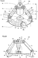
- Fourth link members 8a, 8b, and 8c respectively include base portions 81a to 81c each connected to wall portion 83.
- the two-dimensional shape of base portions 81a to 81c is circular.
- a center shaft 82 is provided at the middle of base portion 81a.
- Base portion 81b of fourth link member 8b is arranged so as to overlap base portion 81a.
- a through hole is formed at the middle of base portion 81b.
- Base portion 81c of fourth link member 8c is arranged so as to lie on base portion 81b.
- a through hole is formed at the middle of base portion 81c.
- Base portions 81b and 81c are stacked on base portion 81a with center shaft 82 inserted in their respective through holes.
- a nut 9 is installed as a fastening member at the tip end portion of center shaft 82.
- Fourth link members 8a, 8b, and 8c are rotatable independently of each other around center shaft 82.
- center shaft 82 of the stacked fourth link members 8a, 8b, and 8c or base portions 81a to 81c can be considered as distal end member 8.
- another member may be connected to center shaft 82 or one of base portions 81a to 81c.
- each of base portions 81a to 81c, center shaft 82, and nut 9 constitute a fifth revolute pair unit.
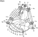
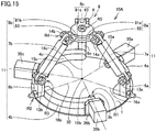
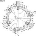
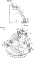
- Parallel link mechanism 10 includes proximal end member 1 and three or more link mechanisms 11.
- Three or more link mechanisms 11 connect proximal end member 1 to distal end member 8.
- Three or more link mechanisms 11 can change the posture of distal end member 8 relative to proximal end member 1.
- Three or more link mechanisms 11 each include first to fourth link members.
- First link members 4a, 4b, and 4c are rotatably connected to proximal end member 1 at the first revolute pair units.
- Second link members 6a, 6b, and 6c are rotatably connected to first link members 4a, 4b, and 4c, respectively, at the second revolute pair units.
- bearing 26 is arranged between shaft portion 42 of each of first link member 4a, 4b, and 4c and the corresponding one of second link members 6a, 6b, and 6c.
- the outer race of bearing 26 may be fixed to second link member 6a, 6b, 6c.
- the inner race of bearing 26 connected to shaft portion 42 may be fixed so as to be sandwiched between nut 5a, 5b, 5c and first link member 4a, 4b, 4c.
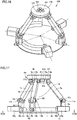
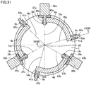
- the link actuation device illustrated in Fig. 8 and Fig. 9 includes parallel link mechanism 10 illustrated in Fig. 1 to Fig. 5 and posture control drive sources 35a, 35b, and 35c.
- Posture control drive sources 35a, 35b, and 35c are installed for all of three link mechanisms 11.
- Posture control drive sources 35a, 35b, and 35c change the posture of distal end member 8 relative to proximal end member 1 as desired by changing the respective angles of rotation around first center axes 15a, 15b, and 15c of first link members 4a, 4b, and 4c.
- the link actuation device includes parallel link mechanism 10 described above and posture control drive sources 35a, 35b, and 35c.
- Posture control drive sources 35a, 35b, and 35c are installed for at least three link mechanisms 11 among three or more link mechanisms 11 and change the posture of distal end member 8 relative to proximal end member 1 as desired.
- distal end member 8 can be moved relative to proximal end member 1 along a sphere around spherical link center point 30 and can be moved also in a direction along fifth center axes 19 independently of the movement along the sphere, in the same manner as the parallel link mechanism illustrated in Fig. 1 to Fig. 5 .
- proximal end member 1 is not present at a position overlapping the second revolute pair units in a two-dimensional view. Therefore, when viewed from the lateral direction along a first surface on the distal end member 8 side of proximal end member 1, the operable range of the second revolute pair units can be expanded to a second surface side (back surface side) on the opposite side to the first surface of proximal end member 1. As a result, the distal end member 8 can be moved to a position near spherical link center point 30.
- Coupling member 13a, 13b, and 13c, the second end of second link member 6a, 6b, 6c, and the first end of third link member 7a, 7b, 7c constitute a third revolute pair unit R3. That is, second link members 6a, 6b, and 6c are rotatably connected to third link members 7a, 7b, and 7c, respectively, at third revolute pair units R3.
- Third link members 7a, 7b, and 7c are rod-shaped members each extending linearly.
- the above-noted through hole 73 is formed at a first end of each of third link members 7a, 7b, and 7c.
- the shape of third link members 7a, 7b, and 7c may be any shape other than the rod-like shape extending linearly.
- third link members 7a, 7b, and 7c each may be a rod-shaped body extending in the form of an arc.
- Coupling members 14a, 14b, 14c are, for example, bolts and nuts. Coupling member 14a, 14b, 14c, the second end of third link member 7a, 7b, 7c, and wall portion 83 of fourth link member 8a, 8b, 8c constitute a fourth revolute pair unit R4. That is, third link members 7a, 7b, and 7c are rotatably connected to fourth link members 8a, 8b, and 8c, respectively, at fourth revolute pair units R4.
- fourth center axes 18a, 18b, and 18c of fourth revolute pair units R4 and fifth center axes 19 of fifth revolute pair units R5 are in a twisted arrangement. More specifically, fourth center axes 18a, 18b, and 18c of fourth revolute pair units R4 extend in directions orthogonal to fifth center axes 19 of fifth revolute pair units R5.
- This shaft serves as, for example, the axis of center of rotation when a drill serving as a working body part is attached to working body 127, and the axis for transmitting rotational motive power to the attached drill.
- working body 1 27 does not necessarily have such a shaft.
- Working body 127 thus can insert work target 128 into the pin slot in workbench 129 or remove work target 128 from workbench 129. It is preferable that, for example, a not-shown load sensor is arranged appropriately and the positioning control of working body 127 is performed by referring to output from the load sensor. In this way, working body 127 can operate minutely in the state illustrated in Fig. 25 to enable minute operation such as inserting and removing a pin into/from the pin slot in workbench 129 without misalignment. As illustrated in Fig. 24 , it is more preferable that the center in a two-dimensional view of working body 127 is arranged at a position overlapping spherical link center point 30. In this manner, the working can be performed more easily.
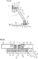
- working body attachment member 121 is fixed to face the proximal end member 1 side of distal end member 8.
- Work target 128 that working body 127 works on can be arranged on the proximal end member 1 side with respect to distal end member 8. In particular, it is preferable that work target 128 can be arranged between distal end member 8 and proximal end member 1.
- work target 128 can be arranged on the opposite side to distal end member 8 relative to proximal end member 1. That is, work target 128 is arranged below proximal end member 1.
- working body 127, proximal end member 1 (proximal end member through hole 130), and work target 128 are arranged in this order from the upper side to the lower side in Fig. 27 .
- Working body 127 can work on work target 128 arranged on the opposite side to distal end member 8 with proximal end member through hole 130 interposed. That is, in the present embodiment, work target 128 is arranged below first link members 4a to 4c in Fig. 27 .
- Work target 128 is spaced apart from proximal end member 1 in the direction along fifth center axis 19. It is preferable that work target 128 is mounted on workbench 129.
- proximal end member 1 has proximal end member through hole 1 30.
- Work target 128 can be arranged on the opposite side to distal end member 8 relative to proximal end member 1.
- Working body 127 can work on work target 128 arranged on the opposite side to distal end member 8 with proximal end member through hole 130 interposed.
- Second link members 6a, 6b, and 6c are rod-shaped members each extending linearly. Through holes 63a, 63b, and 63c are formed at the first ends of second link members 6a, 6b, and 6c, respectively.
- the shape of second link members 6a, 6b, and 6c may be any shape other than the rod-like shape extending linearly.
- second link members 6a, 6b, and 6c each may be a rod-shaped body extending in the form of an arc.
- Fourth link members 8a, 8b, and 8c include base portions 81a, 81b, and 81c connected to wall portions 83a, 83b, and 83c, respectively.
- the two-dimensional shape of base portions 81a, 81b, and 81c is circular.
- center shaft 82 is provided at the middle of base portion 81a
- Base portion 81b of fourth link member 8b is arranged so as to overlap base portion 81a.
- a through hole is formed at the middle of base portion 81b.
- Base portion 81c of fourth link member 8c is arranged so as to overlap base portion 81b.
- a through hole is formed at the middle of base portion 81c.
- Fig. 37 is a diagram illustrating a first working example to which load estimation is applied.
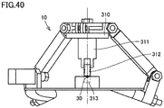
- a hand 211 is mounted as a working body on parallel link mechanism 10.
- a base member 210 is fixed to distal end member 8, and hand 211 is attached to base member 210.
- Hand 211 thus can make a motion similar to that of distal end member 8. That is, ( ⁇ , ⁇ , r) of hand 211 can be controlled by parallel link mechanism 10.
- Center shaft 82 is hollow so that a control cable for controlling grip and release of hand 211 can pass through the inside of center shaft 82 in Fig. 32 .
- the first working example is the operation of inserting connector 212 as a work target into a hole in the workbench 213 installed obliquely, using hand 211 attached to parallel link mechanism 10.
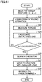
- FIG. 38 is a flowchart illustrating a method of measuring and estimating a load exerted on the working body by calculation.
- Link actuation device 200 includes: first to third posture control drive sources 35a, 35b, and 35c provided corresponding to the first to third link mechanisms among at least three link mechanisms 11 and configured to change the rotation angles at the respective first revolute pair units of first link members 4a, 4b, and 4c; and control device 100 that estimates respective torques of posture control drive sources 35a, 35b, and 35c, based on values of current flowing through posture control drive sources 35a, 35b, and 35c or current command values and estimates a load acting on distal end member 8 based on the estimated torques of posture control drive sources 35a, 35b, and 35c.
- Control device 100 controls each posture control drive source 35a, 35b, 35c such that the operation of pushing a member (for example, connector) gripped by the working body illustrated in Fig. 37 to Fig. 39 into another member (for example, terminal block) or the operation of pulling a member (for example, pin) gripped by the working body illustrated in Fig. 40 and Fig. 41 out of another member (for example, a member having a hole) is performed while the estimated torque of each posture control drive source 35a, 35b, 35c is monitored.
- a member for example, connector
- a member for example, pin
Landscapes
- Engineering & Computer Science (AREA)
- Mechanical Engineering (AREA)
- General Engineering & Computer Science (AREA)
- Robotics (AREA)
- Health & Medical Sciences (AREA)
- General Health & Medical Sciences (AREA)
- Orthopedic Medicine & Surgery (AREA)
- Transmission Devices (AREA)
- Manipulator (AREA)
Applications Claiming Priority (4)
| Application Number | Priority Date | Filing Date | Title |
|---|---|---|---|
| JP2018191816A JP7189528B2 (ja) | 2018-10-10 | 2018-10-10 | パラレルリンク機構およびリンク作動装置 |
| JP2018230100A JP7189531B2 (ja) | 2018-12-07 | 2018-12-07 | リンク作動装置 |
| JP2018229954A JP7189530B2 (ja) | 2018-12-07 | 2018-12-07 | リンク作動装置 |
| PCT/JP2019/039901 WO2020075779A1 (fr) | 2018-10-10 | 2019-10-09 | Mécanisme articulé parallèle et dispositif d'actionnement d'articulation |
Publications (3)
| Publication Number | Publication Date |
|---|---|
| EP3865731A1 true EP3865731A1 (fr) | 2021-08-18 |
| EP3865731A4 EP3865731A4 (fr) | 2022-06-15 |
| EP3865731B1 EP3865731B1 (fr) | 2024-06-05 |
Family
ID=70164615
Family Applications (1)
| Application Number | Title | Priority Date | Filing Date |
|---|---|---|---|
| EP19871283.8A Active EP3865731B1 (fr) | 2018-10-10 | 2019-10-09 | Mécanisme articulé parallèle et dispositif d'actionnement d'articulation |
Country Status (4)
| Country | Link |
|---|---|
| US (1) | US11668375B2 (fr) |
| EP (1) | EP3865731B1 (fr) |
| CN (1) | CN112888878B (fr) |
| WO (1) | WO2020075779A1 (fr) |
Families Citing this family (6)
| Publication number | Priority date | Publication date | Assignee | Title |
|---|---|---|---|---|
| TWI757959B (zh) * | 2020-03-27 | 2022-03-11 | 國立成功大學 | 並聯式三軸線性機器人 |
| JP7438908B2 (ja) * | 2020-09-23 | 2024-02-27 | Ntn株式会社 | パラレルリンク機構およびリンク作動装置 |
| CN113696187B (zh) * | 2021-10-22 | 2022-01-25 | 成都飞机工业(集团)有限责任公司 | 一种适用于双机器人系统的防碰撞方法 |
| JP7754760B2 (ja) * | 2022-03-22 | 2025-10-15 | 株式会社東芝 | パラレルリンク機構、ロボット機構、及び制動方法 |
| JP7652172B2 (ja) * | 2022-10-21 | 2025-03-27 | トヨタ自動車株式会社 | ロボットシステムおよびロボットの駆動方法 |
| CN119458295A (zh) * | 2024-12-27 | 2025-02-18 | 中国科学院沈阳自动化研究所 | 一种空间三自由度平移机构 |
Family Cites Families (26)
| Publication number | Priority date | Publication date | Assignee | Title |
|---|---|---|---|---|
| US5893296A (en) | 1997-03-13 | 1999-04-13 | Ross-Hime Designs, Incorporated | Multiple rotatable links robotic manipulator |
| JP2000094245A (ja) | 1998-09-17 | 2000-04-04 | Fanuc Ltd | パラレルリンク機構を具備する作業装置 |
| JP3995449B2 (ja) * | 2001-11-09 | 2007-10-24 | 三菱電機株式会社 | パラレルメカニズム |
| JP2005144627A (ja) * | 2003-11-18 | 2005-06-09 | Ntn Corp | リンク作動装置 |
| US7478576B2 (en) * | 2005-03-22 | 2009-01-20 | Ross-Hime Designs, Inc. | Robotic manipulator |
| US8469945B2 (en) * | 2006-01-25 | 2013-06-25 | Intuitive Surgical Operations, Inc. | Center robotic arm with five-bar spherical linkage for endoscopic camera |
| CN101225876A (zh) * | 2008-02-20 | 2008-07-23 | 陈茂盛 | 双矩作用轮系的方法及其装置 |
| CN101797435A (zh) * | 2010-03-17 | 2010-08-11 | 上海大学 | 三自由度球面并联机构仿生眼睛 |
| CN103857942B (zh) * | 2011-09-29 | 2016-12-14 | Ntn株式会社 | 连杆动作装置 |
| JP6104701B2 (ja) * | 2013-05-16 | 2017-03-29 | Ntn株式会社 | リンク作動装置 |
| US9579786B2 (en) * | 2013-09-26 | 2017-02-28 | Wen-Der TRUI | Spherical coordinates manipulating mechanism |
| JP6324033B2 (ja) | 2013-11-22 | 2018-05-16 | Ntn株式会社 | リンク作動装置 |
| JP6289973B2 (ja) * | 2014-03-31 | 2018-03-07 | Ntn株式会社 | パラレルリンク機構およびリンク作動装置 |
| JP6453066B2 (ja) * | 2014-12-05 | 2019-01-16 | Ntn株式会社 | リンク作動装置の制御方法 |
| JP6380933B2 (ja) | 2014-12-12 | 2018-08-29 | パナソニックIpマネジメント株式会社 | 電動工具 |
| JP6625322B2 (ja) * | 2014-12-15 | 2019-12-25 | Ntn株式会社 | リンク作動装置 |
| JP6502115B2 (ja) | 2015-02-13 | 2019-04-17 | Ntn株式会社 | リンク作動装置を用いた多関節ロボット |
| JP6527782B2 (ja) * | 2015-08-10 | 2019-06-05 | Ntn株式会社 | パラレルリンク機構を用いた作業装置 |
| JP2017082832A (ja) * | 2015-10-23 | 2017-05-18 | 三菱日立パワーシステムズ株式会社 | リンク装置、可変翼装置、及び回転機械 |
| CN105756877A (zh) * | 2016-04-13 | 2016-07-13 | 武汉钜威天数字化机械制造有限公司 | 对称斜弯主轴结构轴向柱塞液压泵 |
| CN107097211A (zh) * | 2017-04-19 | 2017-08-29 | 中国地质大学(武汉) | 两层两环对称连杆单元及基于此的大折展比伞状可展机构 |
| JP7274846B2 (ja) * | 2018-09-28 | 2023-05-17 | Ntn株式会社 | リンク作動装置 |
| CN113597523B (zh) * | 2019-03-22 | 2024-03-15 | Ntn株式会社 | 平行连杆机构和连杆致动装置 |
| JP7340196B2 (ja) * | 2019-06-05 | 2023-09-11 | 国立大学法人九州工業大学 | リンク作動装置 |
| JP7417917B2 (ja) * | 2019-07-02 | 2024-01-19 | 国立大学法人九州工業大学 | パラレルリンク機構およびリンク作動装置 |
| TW202219420A (zh) * | 2020-11-03 | 2022-05-16 | 崔文德 | 球座標轉向機構 |
-
2019
- 2019-10-09 US US17/283,218 patent/US11668375B2/en active Active
- 2019-10-09 EP EP19871283.8A patent/EP3865731B1/fr active Active
- 2019-10-09 WO PCT/JP2019/039901 patent/WO2020075779A1/fr not_active Ceased
- 2019-10-09 CN CN201980067159.6A patent/CN112888878B/zh active Active
Also Published As
| Publication number | Publication date |
|---|---|
| EP3865731A4 (fr) | 2022-06-15 |
| CN112888878B (zh) | 2024-07-26 |
| EP3865731B1 (fr) | 2024-06-05 |
| WO2020075779A1 (fr) | 2020-04-16 |
| US20210388887A1 (en) | 2021-12-16 |
| US11668375B2 (en) | 2023-06-06 |
| CN112888878A (zh) | 2021-06-01 |
Similar Documents
| Publication | Publication Date | Title |
|---|---|---|
| EP3865731B1 (fr) | Mécanisme articulé parallèle et dispositif d'actionnement d'articulation | |
| US9568075B2 (en) | Robot, robot control device, and robot system | |
| JP6332899B2 (ja) | ロボット | |
| US10363661B2 (en) | Control device, robot, and robot system | |
| EP2703131B1 (fr) | Robot | |
| US9821459B2 (en) | Multi-joint robot having function for repositioning arm | |
| JP6860498B2 (ja) | ロボットシステムの監視装置 | |
| US8812157B2 (en) | Robot system having error detection function of robot and control method thereof | |
| US11717964B2 (en) | Control device for robot that works collaboratively with people | |
| US20150352679A1 (en) | Abnormality diagnosis device for machine tool, and abnormality diagnosis method | |
| JP2017507041A (ja) | 工業用ロボットの安全システム | |
| JP2010064232A (ja) | 搬送システムの異常検出方法および異常検出装置 | |
| JP2019098407A (ja) | ロボット | |
| CN112638600B (zh) | 机器人的控制装置 | |
| US12515326B2 (en) | Method for controlling robot and arm | |
| JP2017007010A (ja) | ロボット、制御装置およびロボットシステム | |
| JP7189530B2 (ja) | リンク作動装置 | |
| JP7375345B2 (ja) | ロボット | |
| CN111660293B (zh) | 水平多关节机器人 | |
| WO2023195146A1 (fr) | Dispositif robot et système de diagnostic à ultrasons | |
| JP2024164671A (ja) | 協働ロボットシステム | |
| WO2025177419A1 (fr) | Dispositif de robot | |
| CN121398944A (zh) | 机器人系统、机器人的控制装置、控制方法以及控制程序 | |
| AU2018236759A1 (en) | Modular robot |
Legal Events
| Date | Code | Title | Description |
|---|---|---|---|
| STAA | Information on the status of an ep patent application or granted ep patent |
Free format text: STATUS: THE INTERNATIONAL PUBLICATION HAS BEEN MADE |
|
| PUAI | Public reference made under article 153(3) epc to a published international application that has entered the european phase |
Free format text: ORIGINAL CODE: 0009012 |
|
| STAA | Information on the status of an ep patent application or granted ep patent |
Free format text: STATUS: REQUEST FOR EXAMINATION WAS MADE |
|
| 17P | Request for examination filed |
Effective date: 20210426 |
|
| AK | Designated contracting states |
Kind code of ref document: A1 Designated state(s): AL AT BE BG CH CY CZ DE DK EE ES FI FR GB GR HR HU IE IS IT LI LT LU LV MC MK MT NL NO PL PT RO RS SE SI SK SM TR |
|
| DAV | Request for validation of the european patent (deleted) | ||
| DAX | Request for extension of the european patent (deleted) | ||
| A4 | Supplementary search report drawn up and despatched |
Effective date: 20220513 |
|
| RIC1 | Information provided on ipc code assigned before grant |
Ipc: B25J 17/02 20060101ALI20220509BHEP Ipc: B25J 9/00 20060101ALI20220509BHEP Ipc: F16H 21/46 20060101AFI20220509BHEP |
|
| GRAP | Despatch of communication of intention to grant a patent |
Free format text: ORIGINAL CODE: EPIDOSNIGR1 |
|
| STAA | Information on the status of an ep patent application or granted ep patent |
Free format text: STATUS: GRANT OF PATENT IS INTENDED |
|
| INTG | Intention to grant announced |
Effective date: 20231103 |
|
| GRAJ | Information related to disapproval of communication of intention to grant by the applicant or resumption of examination proceedings by the epo deleted |
Free format text: ORIGINAL CODE: EPIDOSDIGR1 |
|
| STAA | Information on the status of an ep patent application or granted ep patent |
Free format text: STATUS: REQUEST FOR EXAMINATION WAS MADE |
|
| GRAP | Despatch of communication of intention to grant a patent |
Free format text: ORIGINAL CODE: EPIDOSNIGR1 |
|
| STAA | Information on the status of an ep patent application or granted ep patent |
Free format text: STATUS: GRANT OF PATENT IS INTENDED |
|
| INTC | Intention to grant announced (deleted) | ||
| INTG | Intention to grant announced |
Effective date: 20240124 |
|
| GRAS | Grant fee paid |
Free format text: ORIGINAL CODE: EPIDOSNIGR3 |
|
| GRAA | (expected) grant |
Free format text: ORIGINAL CODE: 0009210 |
|
| STAA | Information on the status of an ep patent application or granted ep patent |
Free format text: STATUS: THE PATENT HAS BEEN GRANTED |
|
| AK | Designated contracting states |
Kind code of ref document: B1 Designated state(s): AL AT BE BG CH CY CZ DE DK EE ES FI FR GB GR HR HU IE IS IT LI LT LU LV MC MK MT NL NO PL PT RO RS SE SI SK SM TR |
|
| REG | Reference to a national code |
Ref country code: CH Ref legal event code: EP |
|
| REG | Reference to a national code |
Ref country code: DE Ref legal event code: R096 Ref document number: 602019053375 Country of ref document: DE |
|
| REG | Reference to a national code |
Ref country code: IE Ref legal event code: FG4D |
|
| REG | Reference to a national code |
Ref country code: LT Ref legal event code: MG9D |
|
| PG25 | Lapsed in a contracting state [announced via postgrant information from national office to epo] |
Ref country code: BG Free format text: LAPSE BECAUSE OF FAILURE TO SUBMIT A TRANSLATION OF THE DESCRIPTION OR TO PAY THE FEE WITHIN THE PRESCRIBED TIME-LIMIT Effective date: 20240605 |
|
| REG | Reference to a national code |
Ref country code: NL Ref legal event code: MP Effective date: 20240605 |
|
| PG25 | Lapsed in a contracting state [announced via postgrant information from national office to epo] |
Ref country code: FI Free format text: LAPSE BECAUSE OF FAILURE TO SUBMIT A TRANSLATION OF THE DESCRIPTION OR TO PAY THE FEE WITHIN THE PRESCRIBED TIME-LIMIT Effective date: 20240605 Ref country code: HR Free format text: LAPSE BECAUSE OF FAILURE TO SUBMIT A TRANSLATION OF THE DESCRIPTION OR TO PAY THE FEE WITHIN THE PRESCRIBED TIME-LIMIT Effective date: 20240605 |
|
| PG25 | Lapsed in a contracting state [announced via postgrant information from national office to epo] |
Ref country code: GR Free format text: LAPSE BECAUSE OF FAILURE TO SUBMIT A TRANSLATION OF THE DESCRIPTION OR TO PAY THE FEE WITHIN THE PRESCRIBED TIME-LIMIT Effective date: 20240906 |
|
| PG25 | Lapsed in a contracting state [announced via postgrant information from national office to epo] |
Ref country code: ES Free format text: LAPSE BECAUSE OF FAILURE TO SUBMIT A TRANSLATION OF THE DESCRIPTION OR TO PAY THE FEE WITHIN THE PRESCRIBED TIME-LIMIT Effective date: 20240605 |
|
| PG25 | Lapsed in a contracting state [announced via postgrant information from national office to epo] |
Ref country code: LV Free format text: LAPSE BECAUSE OF FAILURE TO SUBMIT A TRANSLATION OF THE DESCRIPTION OR TO PAY THE FEE WITHIN THE PRESCRIBED TIME-LIMIT Effective date: 20240605 |
|
| PG25 | Lapsed in a contracting state [announced via postgrant information from national office to epo] |
Ref country code: NO Free format text: LAPSE BECAUSE OF FAILURE TO SUBMIT A TRANSLATION OF THE DESCRIPTION OR TO PAY THE FEE WITHIN THE PRESCRIBED TIME-LIMIT Effective date: 20240905 Ref country code: LV Free format text: LAPSE BECAUSE OF FAILURE TO SUBMIT A TRANSLATION OF THE DESCRIPTION OR TO PAY THE FEE WITHIN THE PRESCRIBED TIME-LIMIT Effective date: 20240605 Ref country code: HR Free format text: LAPSE BECAUSE OF FAILURE TO SUBMIT A TRANSLATION OF THE DESCRIPTION OR TO PAY THE FEE WITHIN THE PRESCRIBED TIME-LIMIT Effective date: 20240605 Ref country code: GR Free format text: LAPSE BECAUSE OF FAILURE TO SUBMIT A TRANSLATION OF THE DESCRIPTION OR TO PAY THE FEE WITHIN THE PRESCRIBED TIME-LIMIT Effective date: 20240906 Ref country code: FI Free format text: LAPSE BECAUSE OF FAILURE TO SUBMIT A TRANSLATION OF THE DESCRIPTION OR TO PAY THE FEE WITHIN THE PRESCRIBED TIME-LIMIT Effective date: 20240605 Ref country code: ES Free format text: LAPSE BECAUSE OF FAILURE TO SUBMIT A TRANSLATION OF THE DESCRIPTION OR TO PAY THE FEE WITHIN THE PRESCRIBED TIME-LIMIT Effective date: 20240605 Ref country code: BG Free format text: LAPSE BECAUSE OF FAILURE TO SUBMIT A TRANSLATION OF THE DESCRIPTION OR TO PAY THE FEE WITHIN THE PRESCRIBED TIME-LIMIT Effective date: 20240605 Ref country code: RS Free format text: LAPSE BECAUSE OF FAILURE TO SUBMIT A TRANSLATION OF THE DESCRIPTION OR TO PAY THE FEE WITHIN THE PRESCRIBED TIME-LIMIT Effective date: 20240905 |
|
| PG25 | Lapsed in a contracting state [announced via postgrant information from national office to epo] |
Ref country code: NL Free format text: LAPSE BECAUSE OF FAILURE TO SUBMIT A TRANSLATION OF THE DESCRIPTION OR TO PAY THE FEE WITHIN THE PRESCRIBED TIME-LIMIT Effective date: 20240605 |
|
| REG | Reference to a national code |
Ref country code: AT Ref legal event code: MK05 Ref document number: 1692669 Country of ref document: AT Kind code of ref document: T Effective date: 20240605 |
|
| PG25 | Lapsed in a contracting state [announced via postgrant information from national office to epo] |
Ref country code: NL Free format text: LAPSE BECAUSE OF FAILURE TO SUBMIT A TRANSLATION OF THE DESCRIPTION OR TO PAY THE FEE WITHIN THE PRESCRIBED TIME-LIMIT Effective date: 20240605 |
|
| PG25 | Lapsed in a contracting state [announced via postgrant information from national office to epo] |
Ref country code: PT Free format text: LAPSE BECAUSE OF FAILURE TO SUBMIT A TRANSLATION OF THE DESCRIPTION OR TO PAY THE FEE WITHIN THE PRESCRIBED TIME-LIMIT Effective date: 20241007 |
|
| PG25 | Lapsed in a contracting state [announced via postgrant information from national office to epo] |
Ref country code: PT Free format text: LAPSE BECAUSE OF FAILURE TO SUBMIT A TRANSLATION OF THE DESCRIPTION OR TO PAY THE FEE WITHIN THE PRESCRIBED TIME-LIMIT Effective date: 20241007 |
|
| PG25 | Lapsed in a contracting state [announced via postgrant information from national office to epo] |
Ref country code: PL Free format text: LAPSE BECAUSE OF FAILURE TO SUBMIT A TRANSLATION OF THE DESCRIPTION OR TO PAY THE FEE WITHIN THE PRESCRIBED TIME-LIMIT Effective date: 20240605 |
|
| PG25 | Lapsed in a contracting state [announced via postgrant information from national office to epo] |
Ref country code: EE Free format text: LAPSE BECAUSE OF FAILURE TO SUBMIT A TRANSLATION OF THE DESCRIPTION OR TO PAY THE FEE WITHIN THE PRESCRIBED TIME-LIMIT Effective date: 20240605 |
|
| PG25 | Lapsed in a contracting state [announced via postgrant information from national office to epo] |
Ref country code: AT Free format text: LAPSE BECAUSE OF FAILURE TO SUBMIT A TRANSLATION OF THE DESCRIPTION OR TO PAY THE FEE WITHIN THE PRESCRIBED TIME-LIMIT Effective date: 20240605 Ref country code: IS Free format text: LAPSE BECAUSE OF FAILURE TO SUBMIT A TRANSLATION OF THE DESCRIPTION OR TO PAY THE FEE WITHIN THE PRESCRIBED TIME-LIMIT Effective date: 20241005 |
|
| PG25 | Lapsed in a contracting state [announced via postgrant information from national office to epo] |
Ref country code: CZ Free format text: LAPSE BECAUSE OF FAILURE TO SUBMIT A TRANSLATION OF THE DESCRIPTION OR TO PAY THE FEE WITHIN THE PRESCRIBED TIME-LIMIT Effective date: 20240605 |
|
| PG25 | Lapsed in a contracting state [announced via postgrant information from national office to epo] |
Ref country code: SK Free format text: LAPSE BECAUSE OF FAILURE TO SUBMIT A TRANSLATION OF THE DESCRIPTION OR TO PAY THE FEE WITHIN THE PRESCRIBED TIME-LIMIT Effective date: 20240605 Ref country code: RO Free format text: LAPSE BECAUSE OF FAILURE TO SUBMIT A TRANSLATION OF THE DESCRIPTION OR TO PAY THE FEE WITHIN THE PRESCRIBED TIME-LIMIT Effective date: 20240605 |
|
| PG25 | Lapsed in a contracting state [announced via postgrant information from national office to epo] |
Ref country code: SM Free format text: LAPSE BECAUSE OF FAILURE TO SUBMIT A TRANSLATION OF THE DESCRIPTION OR TO PAY THE FEE WITHIN THE PRESCRIBED TIME-LIMIT Effective date: 20240605 |
|
| PG25 | Lapsed in a contracting state [announced via postgrant information from national office to epo] |
Ref country code: SM Free format text: LAPSE BECAUSE OF FAILURE TO SUBMIT A TRANSLATION OF THE DESCRIPTION OR TO PAY THE FEE WITHIN THE PRESCRIBED TIME-LIMIT Effective date: 20240605 Ref country code: SK Free format text: LAPSE BECAUSE OF FAILURE TO SUBMIT A TRANSLATION OF THE DESCRIPTION OR TO PAY THE FEE WITHIN THE PRESCRIBED TIME-LIMIT Effective date: 20240605 Ref country code: RO Free format text: LAPSE BECAUSE OF FAILURE TO SUBMIT A TRANSLATION OF THE DESCRIPTION OR TO PAY THE FEE WITHIN THE PRESCRIBED TIME-LIMIT Effective date: 20240605 Ref country code: PL Free format text: LAPSE BECAUSE OF FAILURE TO SUBMIT A TRANSLATION OF THE DESCRIPTION OR TO PAY THE FEE WITHIN THE PRESCRIBED TIME-LIMIT Effective date: 20240605 Ref country code: IS Free format text: LAPSE BECAUSE OF FAILURE TO SUBMIT A TRANSLATION OF THE DESCRIPTION OR TO PAY THE FEE WITHIN THE PRESCRIBED TIME-LIMIT Effective date: 20241005 Ref country code: EE Free format text: LAPSE BECAUSE OF FAILURE TO SUBMIT A TRANSLATION OF THE DESCRIPTION OR TO PAY THE FEE WITHIN THE PRESCRIBED TIME-LIMIT Effective date: 20240605 Ref country code: CZ Free format text: LAPSE BECAUSE OF FAILURE TO SUBMIT A TRANSLATION OF THE DESCRIPTION OR TO PAY THE FEE WITHIN THE PRESCRIBED TIME-LIMIT Effective date: 20240605 Ref country code: AT Free format text: LAPSE BECAUSE OF FAILURE TO SUBMIT A TRANSLATION OF THE DESCRIPTION OR TO PAY THE FEE WITHIN THE PRESCRIBED TIME-LIMIT Effective date: 20240605 |
|
| PG25 | Lapsed in a contracting state [announced via postgrant information from national office to epo] |
Ref country code: IT Free format text: LAPSE BECAUSE OF FAILURE TO SUBMIT A TRANSLATION OF THE DESCRIPTION OR TO PAY THE FEE WITHIN THE PRESCRIBED TIME-LIMIT Effective date: 20240605 |
|
| REG | Reference to a national code |
Ref country code: DE Ref legal event code: R097 Ref document number: 602019053375 Country of ref document: DE |
|
| PLBE | No opposition filed within time limit |
Free format text: ORIGINAL CODE: 0009261 |
|
| STAA | Information on the status of an ep patent application or granted ep patent |
Free format text: STATUS: NO OPPOSITION FILED WITHIN TIME LIMIT |
|
| PG25 | Lapsed in a contracting state [announced via postgrant information from national office to epo] |
Ref country code: DK Free format text: LAPSE BECAUSE OF FAILURE TO SUBMIT A TRANSLATION OF THE DESCRIPTION OR TO PAY THE FEE WITHIN THE PRESCRIBED TIME-LIMIT Effective date: 20240605 |
|
| 26N | No opposition filed |
Effective date: 20250306 |
|
| REG | Reference to a national code |
Ref country code: CH Ref legal event code: PL |
|
| GBPC | Gb: european patent ceased through non-payment of renewal fee |
Effective date: 20241009 |
|
| PG25 | Lapsed in a contracting state [announced via postgrant information from national office to epo] |
Ref country code: MC Free format text: LAPSE BECAUSE OF FAILURE TO SUBMIT A TRANSLATION OF THE DESCRIPTION OR TO PAY THE FEE WITHIN THE PRESCRIBED TIME-LIMIT Effective date: 20240605 |
|
| PG25 | Lapsed in a contracting state [announced via postgrant information from national office to epo] |
Ref country code: GB Free format text: LAPSE BECAUSE OF NON-PAYMENT OF DUE FEES Effective date: 20241009 |
|
| PG25 | Lapsed in a contracting state [announced via postgrant information from national office to epo] |
Ref country code: LU Free format text: LAPSE BECAUSE OF NON-PAYMENT OF DUE FEES Effective date: 20241009 Ref country code: BE Free format text: LAPSE BECAUSE OF NON-PAYMENT OF DUE FEES Effective date: 20241031 |
|
| PG25 | Lapsed in a contracting state [announced via postgrant information from national office to epo] |
Ref country code: CH Free format text: LAPSE BECAUSE OF NON-PAYMENT OF DUE FEES Effective date: 20241031 |
|
| REG | Reference to a national code |
Ref country code: BE Ref legal event code: MM Effective date: 20241031 |
|
| PG25 | Lapsed in a contracting state [announced via postgrant information from national office to epo] |
Ref country code: SE Free format text: LAPSE BECAUSE OF FAILURE TO SUBMIT A TRANSLATION OF THE DESCRIPTION OR TO PAY THE FEE WITHIN THE PRESCRIBED TIME-LIMIT Effective date: 20240605 |
|
| PGFP | Annual fee paid to national office [announced via postgrant information from national office to epo] |
Ref country code: FR Payment date: 20250908 Year of fee payment: 7 |
|
| PG25 | Lapsed in a contracting state [announced via postgrant information from national office to epo] |
Ref country code: IE Free format text: LAPSE BECAUSE OF NON-PAYMENT OF DUE FEES Effective date: 20241009 |
|
| PGFP | Annual fee paid to national office [announced via postgrant information from national office to epo] |
Ref country code: DE Payment date: 20250910 Year of fee payment: 7 |
|
| PG25 | Lapsed in a contracting state [announced via postgrant information from national office to epo] |
Ref country code: CY Free format text: LAPSE BECAUSE OF FAILURE TO SUBMIT A TRANSLATION OF THE DESCRIPTION OR TO PAY THE FEE WITHIN THE PRESCRIBED TIME-LIMIT; INVALID AB INITIO Effective date: 20191009 |
|
| PG25 | Lapsed in a contracting state [announced via postgrant information from national office to epo] |
Ref country code: HU Free format text: LAPSE BECAUSE OF FAILURE TO SUBMIT A TRANSLATION OF THE DESCRIPTION OR TO PAY THE FEE WITHIN THE PRESCRIBED TIME-LIMIT; INVALID AB INITIO Effective date: 20191009 |