EP3865771B1 - Verfahren zum betreiben einer feuerungsanlage - Google Patents
Verfahren zum betreiben einer feuerungsanlage Download PDFInfo
- Publication number
- EP3865771B1 EP3865771B1 EP20000469.5A EP20000469A EP3865771B1 EP 3865771 B1 EP3865771 B1 EP 3865771B1 EP 20000469 A EP20000469 A EP 20000469A EP 3865771 B1 EP3865771 B1 EP 3865771B1
- Authority
- EP
- European Patent Office
- Prior art keywords
- chute
- grate
- determined
- combustion
- line
- Prior art date
- Legal status (The legal status is an assumption and is not a legal conclusion. Google has not performed a legal analysis and makes no representation as to the accuracy of the status listed.)
- Active
Links
Images


Classifications
-
- F—MECHANICAL ENGINEERING; LIGHTING; HEATING; WEAPONS; BLASTING
- F23—COMBUSTION APPARATUS; COMBUSTION PROCESSES
- F23G—CREMATION FURNACES; CONSUMING WASTE PRODUCTS BY COMBUSTION
- F23G5/00—Incineration of waste; Incinerator constructions; Details, accessories or control therefor
- F23G5/50—Control or safety arrangements
-
- F—MECHANICAL ENGINEERING; LIGHTING; HEATING; WEAPONS; BLASTING
- F23—COMBUSTION APPARATUS; COMBUSTION PROCESSES
- F23G—CREMATION FURNACES; CONSUMING WASTE PRODUCTS BY COMBUSTION
- F23G5/00—Incineration of waste; Incinerator constructions; Details, accessories or control therefor
- F23G5/44—Details; Accessories
- F23G5/442—Waste feed arrangements
-
- F—MECHANICAL ENGINEERING; LIGHTING; HEATING; WEAPONS; BLASTING
- F23—COMBUSTION APPARATUS; COMBUSTION PROCESSES
- F23G—CREMATION FURNACES; CONSUMING WASTE PRODUCTS BY COMBUSTION
- F23G5/00—Incineration of waste; Incinerator constructions; Details, accessories or control therefor
- F23G5/44—Details; Accessories
- F23G5/46—Recuperation of heat
-
- F—MECHANICAL ENGINEERING; LIGHTING; HEATING; WEAPONS; BLASTING
- F23—COMBUSTION APPARATUS; COMBUSTION PROCESSES
- F23N—REGULATING OR CONTROLLING COMBUSTION
- F23N5/00—Systems for controlling combustion
- F23N5/02—Systems for controlling combustion using devices responsive to thermal changes or to thermal expansion of a medium
- F23N5/08—Systems for controlling combustion using devices responsive to thermal changes or to thermal expansion of a medium using light-sensitive elements
- F23N5/082—Systems for controlling combustion using devices responsive to thermal changes or to thermal expansion of a medium using light-sensitive elements using electronic means
-
- F—MECHANICAL ENGINEERING; LIGHTING; HEATING; WEAPONS; BLASTING
- F23—COMBUSTION APPARATUS; COMBUSTION PROCESSES
- F23G—CREMATION FURNACES; CONSUMING WASTE PRODUCTS BY COMBUSTION
- F23G2205/00—Waste feed arrangements
- F23G2205/16—Waste feed arrangements using chute
-
- F—MECHANICAL ENGINEERING; LIGHTING; HEATING; WEAPONS; BLASTING
- F23—COMBUSTION APPARATUS; COMBUSTION PROCESSES
- F23G—CREMATION FURNACES; CONSUMING WASTE PRODUCTS BY COMBUSTION
- F23G2207/00—Control
- F23G2207/10—Arrangement of sensing devices
- F23G2207/112—Arrangement of sensing devices for waste supply flowrate
-
- F—MECHANICAL ENGINEERING; LIGHTING; HEATING; WEAPONS; BLASTING
- F23—COMBUSTION APPARATUS; COMBUSTION PROCESSES
- F23G—CREMATION FURNACES; CONSUMING WASTE PRODUCTS BY COMBUSTION
- F23G2207/00—Control
- F23G2207/20—Waste supply
-
- F—MECHANICAL ENGINEERING; LIGHTING; HEATING; WEAPONS; BLASTING
- F23—COMBUSTION APPARATUS; COMBUSTION PROCESSES
- F23G—CREMATION FURNACES; CONSUMING WASTE PRODUCTS BY COMBUSTION
- F23G2900/00—Special features of, or arrangements for incinerators
- F23G2900/55—Controlling; Monitoring or measuring
- F23G2900/55007—Sensors arranged in waste loading zone, e.g. feed hopper level
-
- F—MECHANICAL ENGINEERING; LIGHTING; HEATING; WEAPONS; BLASTING
- F23—COMBUSTION APPARATUS; COMBUSTION PROCESSES
- F23G—CREMATION FURNACES; CONSUMING WASTE PRODUCTS BY COMBUSTION
- F23G5/00—Incineration of waste; Incinerator constructions; Details, accessories or control therefor
- F23G5/002—Incineration of waste; Incinerator constructions; Details, accessories or control therefor characterised by their grates
-
- F—MECHANICAL ENGINEERING; LIGHTING; HEATING; WEAPONS; BLASTING
- F23—COMBUSTION APPARATUS; COMBUSTION PROCESSES
- F23N—REGULATING OR CONTROLLING COMBUSTION
- F23N2223/00—Signal processing; Details thereof
- F23N2223/48—Learning / Adaptive control
-
- F—MECHANICAL ENGINEERING; LIGHTING; HEATING; WEAPONS; BLASTING
- F23—COMBUSTION APPARATUS; COMBUSTION PROCESSES
- F23N—REGULATING OR CONTROLLING COMBUSTION
- F23N2229/00—Flame sensors
- F23N2229/20—Camera viewing
-
- F—MECHANICAL ENGINEERING; LIGHTING; HEATING; WEAPONS; BLASTING
- F23—COMBUSTION APPARATUS; COMBUSTION PROCESSES
- F23N—REGULATING OR CONTROLLING COMBUSTION
- F23N2900/00—Special features of, or arrangements for controlling combustion
- F23N2900/05006—Controlling systems using neuronal networks
-
- G—PHYSICS
- G05—CONTROLLING; REGULATING
- G05B—CONTROL OR REGULATING SYSTEMS IN GENERAL; FUNCTIONAL ELEMENTS OF SUCH SYSTEMS; MONITORING OR TESTING ARRANGEMENTS FOR SUCH SYSTEMS OR ELEMENTS
- G05B13/00—Adaptive control systems, i.e. systems automatically adjusting themselves to have a performance which is optimum according to some preassigned criterion
- G05B13/02—Adaptive control systems, i.e. systems automatically adjusting themselves to have a performance which is optimum according to some preassigned criterion electric
- G05B13/0265—Adaptive control systems, i.e. systems automatically adjusting themselves to have a performance which is optimum according to some preassigned criterion electric the criterion being a learning criterion
- G05B13/027—Adaptive control systems, i.e. systems automatically adjusting themselves to have a performance which is optimum according to some preassigned criterion electric the criterion being a learning criterion using neural networks only
Definitions
- the invention relates to a method for operating a furnace.
- a firing system it is important that a defined quantity of material runs through the firing system from the feed chute via the grate to the slag discharge.
- a hopper is filled with material in batch mode using a gripper.
- This material is a positive energy balance chemically convertible material and is preferably waste for the purposes of this application.
- This material can be wet and heavy and can slide down the hopper quickly, it can settle on the walls of the hopper, get stuck in the hopper, or for other reasons cannot flow continuously through the hopper into the area of the furnace grate.
- the material ignites and burns with varying intensity and heat release, depending on the composition of the waste. If several grates are operated next to each other, there is also the possibility that the garbage will also burn out differently when the garbage moves over different grate tracks.
- EP 0 352 620 A2 and WO 90/09552 A1 each disclose a method for controlling an incinerator with an incineration grate.
- combustion plants especially waste incineration plants, are used for the environmentally friendly disposal of waste with the lowest possible emissions and for the generation of energy.
- the heat release should be as constant as possible, on the one hand to achieve controlled combustion and on the other hand to provide a steam output that is as constant as possible.
- the invention is therefore based on the object of keeping the combustion output that is ultimately generated, which is generally reflected in the steam output, as constant as possible.
- This object is achieved with a method for operating a firing system with a feed chute and a camera for capturing an image of the surface of the chute in that the chute has a chute on which material flows to a grate, and with an image evaluation the cover of the Chute and in particular the slide with material and / or the change in position and thus the movement of individual components or surface areas within the chute is determined.
- the chute is a surface of the feed chute that is inclined relative to the horizontal.
- the chute can be a lower or a side surface of the feed chute, the material fed onto the chute sliding along these surfaces in order to reach the furnace.
- the wall material of the chute which is usually a sheet of iron, is covered and is static or changing depending on the movement of the feed piston, then the material can be assumed to slide properly to the furnace.
- the movement of the fuel on the chute towards the furnace is coupled with the movement of the feed piston. If this moves, the material moves. If this does not move, the material does not move. If this relationship does not exist and the material moves even though the feeder is not moving, or the material does not move even though the feeder is moving, there is an error indicating that the material is not sliding properly to the furnace.
- a vertical wall area or an area on the slide can be observed.
- a surface of the chute is preferably observed which, as a chute, has the smallest possible angle with respect to the horizontal, since a surface detected in the event of incorrect subsequent sliding is then larger.
- a preferred exemplary embodiment provides that the position of at least one boundary point in the image is determined at which material covers the chute on the one hand and the surface of the chute is visible on the other. It is advantageous if several border points are determined and in this case it is also possible to determine the position of a line connecting the border points in the image.
- Defined points on the side of the chute can also be calculated to determine how full the chute is. In this case, the distance of at least one limit point to a defined point on one side of the chute is determined.
- the image of the chute surface can be divided into several zones. This makes it possible to determine the coverage in the individual zones with the image evaluation. From this, the material flow can be determined at any point within the chute.
- a dynamic behavior of the firing system can be determined if several images are recorded at intervals and the filling level in the chute is determined by means of the image evaluation from the change in the images. This also makes it possible to determine the speed at which the material flows to the furnace from the change in the images. The speed is then a way of measuring the amount of material that flows to the grate.
- the change in position and thus the movement of individual components or surface areas within the chute can be tracked using imaging methods. In this case, it is necessary to take several pictures at intervals of time. These images can be captured as still images or as a movie.
- significant components or areas are selected after the material has been loaded and their movement is detected (until the selected components are obscured).
- the selection is automated and can be based on structures and objects learned by means of artificial intelligence, based on significant shapes, colors or outlines of material within the chute or based on random or defined areas within the be hit.
- this method allows the material flow within the chute to be determined. The method can be used individually or in addition to detecting individual points in the transition between the chute and the material.
- a fault detected in the area of the feed chute often leads directly to faults in combustion on the grate. It is therefore proposed in a further development that an action is triggered in the event of a predetermined covering or a predetermined change in the covering of the chute and in particular the chute with material or a specific material flow depending on the movement of the feeder.
- This action can be an early intervention in the regulation of the system. For example, a clearing stroke can be initiated and, in the event of an uncontrolled flow of waste, an adjustment can be achieved through air management and/or the grate speed. It is also possible to intervene in the feeder speed and/or position in the event of uncontrolled waste flow in order to optimize incineration.
- assistance signal to the crane driver
- direct intervention in the material feed into the chute by the crane is possible, depending on the level detected in the chute.
- an image evaluation makes it possible to determine the transition from material to background as the position of at least one point and preferably at the line in the flow direction of the material at the end of the image.
- the height of a line that can be determined by the transition from material to chute can be evaluated on the determined image when the camera is stationary. For this, individual points or a continuous line, which can also be averaged, can be determined.
- this makes it possible for the point or the line to be compared with a limit value and for an action to be triggered if this limit value is exceeded.
- This action corresponds to the above actions.
- an image evaluation can also be used at the end of the firing grate to affect the firing system.
- Firing systems with a grate at the end of which a camera is arranged are known.
- the end of the grate forms the area where the slag accumulates on the grate.
- a camera positioned there, directed from the slag area towards the combustion bed, shows how the material burns in the combustion bed.
- the brightness shows the intensity of the burnout and the location of the brightness shows where the material burns out particularly well on the grate.
- the change in the burn-out line allows conclusions to be drawn about the stoking effect of the grate and the primary air management and makes it possible to adjust these parameters in order to improve combustion.
- the burn-out line also makes it possible to equalize the amount of fuel between different grate tracks.
- the movement of individual components or fractions within the combustion bed can be tracked using imaging processes. Fractions are areas that are recognizable as such by their structure or have been selected as areas. In this case, it is necessary to take several pictures at intervals of time.
- significant components or fractions are selected according to the material input and their movement is detected until the selected components are covered.
- the selection is automated and can be made based on structures and objects learned by means of artificial intelligence, based on significant shapes, colors or outlines of material within the chute or based on random or defined areas within the chute. This method allows the material flow within the combustion bed to be determined. The method can be used individually or in addition to detecting the height of the combustion bed and the length of the fire.
- This information can be compared with a target value, so that an action can be triggered depending on the firing position and/or the thickness of the combustion bed and/or the movement of individual components or surface areas.
- This action can in turn, as indicated above, affect the conveyance on the grate or the gas conditions. It is therefore proposed as a further development that depending on the position of the fire on the grate, in particular in the longitudinal direction of the grate, and/or the thickness of the combustion bed, a control or regulation of the combustion system is automatically acted upon. And therefore it is suggested that the grate speed is controlled or regulated depending on the firing position and/or the fire bed thickness. It is particularly advantageous if the grate speed of individual grate zones or adjacent grate tracks is controlled or regulated.
- the airflow of the firing system can also be controlled or regulated as a function of the thickness of the combustion bed and/or the position of the fire.
- the primary air of the furnace is controlled or regulated as a function of the firing position and/or the thickness of the combustion bed.
- the furnace has individual grate tracks that are analyzed using image analysis, so that the feeding of individual grate tracks of the furnace can be controlled or regulated depending on the thickness of the combustion bed and/or the position of the furnace. For example, the stroke length can be adjusted or a zero point offset for the feeder can be set.
- the individual grate tracks have several drives, so that the intensity of the stoking movement of the individual grate zones can be controlled or regulated depending on the thickness of the combustion bed and/or the position of the fire. For example, the stoking speed can be adjusted.
- a coupling of both optical camera systems is advantageous. In this way, interventions triggered by the camera above the chute can be checked using the camera at the end of the combustion bed. Through the use of control circuits or neural networks, it is possible to optimize the interventions triggered.
- a grate which has a number of grate zones and/or a number of grate tracks and a number of fuel supply devices, in which a uniform release of heat is set on the grate the temperature per grate zone and/or per grate track is measured and the fuel supply devices are controlled as a function of the measured temperature.
- At least one temperature measuring device is used per grate zone and/or per grate lane.
- the temperature can be measured parallel to the grate segments or in the first radiation path.
- the temperature change should be recorded close to the furnace and at the latest at a level of the radiation path into which the flue gases reach after 1 to 15 seconds.
- Firing system 1 shown is a grate furnace with a grate 2, under which a primary air supply 3 is arranged.
- the material 4 burned on the grate 2 is conveyed via the grate 3 to a slag discharge 5 .
- the flue gas 6 resulting from the burning of the material 4 on the grate 2 enters a first pass 7 and from there into further passes 8 and 9 in order to heat water which is used as steam for a power generation plant (not shown).
- waste passes as material 4 from the chute 10 through a feed channel 11 to the grate 2 and from there to the slag discharge 5.
- a camera 12 is used to capture the surface 13 of the chute and display it as an image 14.
- Another camera 34 at the end 15 of the grate 2 is aimed at the material 4 on the grate 2 and the flame 16 produced during the combustion of the material 4 .
- a third camera 17 can be used to observe the flame 16 generated on the grate 2 from above.
- the figure 2 shows how material 4 can be thrown into the feed chute 10 by means of a gripper 20, which material then reaches the channel 4 on a chute 21 and from there to the fire grate 2.
- the camera 12 is connected to an image evaluation 22 which determines the covering of the chute 10 and in particular the chute 21 with material 4 .
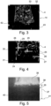
- the figure 3 and especially their in figure 4 The enlargement shown shows areas 23 in which the chute 21 is covered with material 4, and an area 24 and an area 43 in which the top of the chute 21 can be seen, since it is not covered with material 4 in this area 24.
- Bars 25, 26 and 27 form boundary points in Figure 4, at which material 4 covers the chute 10 on the one hand and the surface of the chute 10 is visible on the other hand.
- points 29, 30 and 31 are indicated as vertical bars. This allows the intersection between horizontal To determine bars 25, 26 and 27 and vertical bars 29, 30 and 31 in order to deduce the filling of the chute 10.
- Line 33 shows the transition between the material 4 and the background 33.
- the height of this line 33 in Figure 4 and deviations from a straight line provide information about the material in the chute 10.
- the figure 5 shows an image 35 which was recorded with a camera 14 in the flow direction of the material 4 at the end of the grate 2 . From this image 35, an image evaluation 36 determines the thickness of the combustion bed 37 as the distance between a line 38 and a line 41.
- the line 38 results from the contrast between the light area 39 of the flames 16 and the dark area 40 of the slag.
- the height of the line 41 in Figure 35 can be determined by trials and also results from a system that does not yet have any material 4 on the grate 2 .
- the image evaluation devices 22 and 36 are connected to the controller 41 of the firing system 1, so that if a limit value is exceeded, the controller 41 of the firing system can be acted upon to adjust the grate speed and/or the air supply to the firing system 1 depending on the determined at the chute 10 Limit and / or the thickness of the combustion bed 37 to control or regulate.
- FIG 6 shows a fire grate 2 and above it the first flue gas flue 7, and then the second flue gas flue 8.
- a temperature measuring device 49 is arranged parallel to the grate 2 or measuring horizontally. This creates a level 52 of temperature measurement above the secondary air level 54 .
- the figure 7 shows an exemplary arrangement of the temperature measuring devices for a system with 3 grate tracks 46, 47 and 48. Each grate track is assigned a temperature measuring device 49, 50 and 51.
Landscapes
- Engineering & Computer Science (AREA)
- Mechanical Engineering (AREA)
- General Engineering & Computer Science (AREA)
- Environmental & Geological Engineering (AREA)
- Chemical & Material Sciences (AREA)
- Combustion & Propulsion (AREA)
- Incineration Of Waste (AREA)
- Control Of Combustion (AREA)
- Solid-Fuel Combustion (AREA)
- Waste-Gas Treatment And Other Accessory Devices For Furnaces (AREA)
Description
- Die Erfindung betrifft ein Verfahren zum Betreiben einer Feuerungsanlage. Beim Betreiben einer Feuerungsanlage ist es wichtig, dass von der Aufgabeschurre über den Feuerrost bis zum Schlackenaustrag eine definierte Menge Material pro Zeit die Feuerungsanlage durchläuft.
- An der Aufgabeschurre wird ein Trichter im Chargenbetrieb über einen Greifer mit Material gefüllt. Dieses Material ist ein mit positiver Energiebilanz, chemisch umwandelbar Stoff und im Rahmen dieser Anmeldung vorzugsweise Müll. Dieses Material kann nass und schwer sein und schnell in den Trichter hinein rutschen, es kann auf den Wandungen des Trichters liegen bleiben, sich im Trichter versperren oder aus anderen Gründen nicht kontinuierlich über den Trichter in den Bereich des Feuerungsrostes gelangen.
- Auf dem Feuerungsrost entzündet sich das Material und es brennt mit unterschiedlicher Intensität und Wärmefreisetzung, abhängig von der Zusammensetzung des Mülls. Wenn mehrere Roste nebeneinander betrieben werden, besteht darüber hinaus die Möglichkeit, dass bei der Bewegung des Mülls über unterschiedliche Rostbahnen der Müll auch unterschiedlich ausbrennt.
-
EP 0 352 620 A2 undWO 90/09552 A1 - In vielen Fällen dienen Feuerungsanlagen, insbesondere Müllverbrennungsanlagen, der umweltfreundlichen Entsorgung von Abfällen mit möglichst geringen Emissionen und der Erzeugung von Energie. Hierfür sollte die Wärmefreisetzung möglichst konstant sein, um einerseits eine kontrollierte Verbrennung zu erreichen und andererseits eine möglichst unveränderte konstante Dampfleistung bereitzustellen.
- Der Erfindung liegt daher die Aufgabe zu Grunde, die letztlich erzeugte Feuerungsleistung, die sich in der Regel in der Dampfleistung widerspiegelt, möglichst konstant zu halten.
- Diese Aufgabe wird mit einem Verfahren zum Betreiben einer Feuerungsanlage mit einer Aufgabeschurre und einer Kamera zur Erfassung eines Bildes der Oberfläche der Schurre dadurch gelöst, dass die Schurre eine Rutsche aufweist, auf der Material zu einem Rost fließt, und mit einer Bildauswertung die Abdeckung der der Schurre und insbesondere der Rutsche mit Material und/oder die Positionsänderung und damit die Bewegung einzelner Komponenten oder Flächenbereiche innerhalb der Schurre ermittelt wird.
- Die Rutsche ist dabei eine gegenüber der Waagerechten schräge Fläche der Aufgabeschurre. Die Rutsche kann eine untere oder eine seitliche Fläche der Aufgabeschurre sein, wobei an diesen Flächen das auf die Schurre aufgegebene Material entlang gleitet, um zur Feuerungsanlage zu gelangen.
- Sofern in einem bestimmten Bereich das Wandmaterial der Rutsche, das in der Regel eine Eisenfläche ist, bedeckt ist und abhängig von der Bewegung des Beschicckolbens statisch ist oder sich die Bedeckung verändert, ist davon auszugehen, dass das Material ordnungsgemäß zur Feuerungsanlage gleitet. Die Bewegung des Brennstoffs auf der Rutsche in Richtung der Feuerung ist mit der Bewegung des Beschickkolbens gekoppelt. Bewegt sich dieser so bewegt sich das Material. Bewegt sich dieser nicht, so bewegt sich das Material nicht. Ist dieser Zusammenhang nicht gegeben und bewegt sich das Material obwohl sich der Beschicker nicht bewegt oder bewegt sich das Material nicht obwohl sich der Beschicker bewegt, besteht ein Fehler, der darauf hinweist, dass das Material nicht ordnungsmäßig zur Feuerungsanlage gleitet. Dabei kann ein senkrechter Wandbereich oder ein Bereich auf der Rutsche beobachtet werden. Vorzugsweise wird eine Fläche der Schurre beobachtet, die als Rutsche gegenüber der Waagrechten einen möglichst kleinen Winkel hat, da dann eine bei fehlerhaftem Nachrutschen detektierte Fläche größer ist.
- Daher wird vorzugsweise die Abdeckung einer unteren Seite der Schurre mit Material ausgewertet, während die anderen Seiten der Schurre in der Regel zusätzliche Anhaltspunkte bilden.
- Ein bevorzugtes Ausführungsbeispiel sieht vor, dass die Position zumindest eines Grenzpunktes im Bild ermittelt wird, an dem einerseits Material die Schurre abdeckt und andererseits die Oberfläche der Schurre sichtbar ist. Vorteilhaft ist es, wenn mehrere Grenzpunkte ermittelt werden und in diesem Fall ist es auch möglich, die Position einer die Grenzpunkte verbindenden Linie im Bild zu ermitteln.
- Zur Ermittlung der Befüllung der Schurre können auch definierte Punkte an der Seite der Schurre berechnet werden. In diesem Fall wird der Abstand mindestens eines Grenzpunktes zu einem definierten Punkt an einer Seite der Schurre ermittelt.
- Mit anderen Worten ausgedrückt ist es vorteilhaft, die sichtbare Linie zwischen Schurre und Material zu ermitteln. Zur Erhöhung der Genauigkeit der Bildauswertung kann das Bild der Oberfläche der Schurre in mehrere Zonen aufgeteilt werden. Dies ermöglicht es, mit der Bildauswertung die Abdeckung in den einzelnen Zonen zu ermitteln. Daraus kann der Materialstrom an jeder beliebigen Stelle innerhalb der Schurre ermittelt werden. Ein dynamisches Verhalten der Feuerungsanlage kann ermittelt werden, wenn in zeitlichem Abstand mehrere Bilder aufgenommen werden und mittels der Bildauswertung aus der Veränderung der Bilder das Füllniveau in der Schurre ermittelt wird. Dies ermöglicht es dann auch, aus der Veränderung der Bilder die Geschwindigkeit zu ermitteln, mit der das Material zur Feuerungsanlage fließt. Die Geschwindigkeit bildet sodann eine Möglichkeit auch die Materialmenge zu erfassen, die zum Rost fließt.
- Außerdem können mittels bildgebenden Verfahren die Positionsänderung und damit die Bewegung einzelner Komponenten oder Flächenbereiche innerhalb der Schurre nachverfolgt werden. Hierbei ist es notwendig in zeitlichem Abstand mehrere Bilder aufzunehmen. Diese Bilder können als Einzelbilder oder als Film aufgenommen werden. Innerhalb der Schurre werden signifikante Komponenten oder Flächenbereiche nach der Aufgabe des Materials ausgewählt und deren Bewegung detektiert (bis die ausgewählten Komponenten verdeckt werden). Die Auswahl erfolgt automatisiert und kann basierend auf mittels künstlicher Intelligenz eingelernter Strukturen und Gegenstände, basierend auf signifikanten Formen, Farben oder Umrissen von Material innerhalb der Schurre oder basierend auf zufälligen bzw. definierten Bereichen innerhalb der Schurre getroffen werden. Dieses Verfahren erlaubt, wie das Verfahren zur Erkennung einzelner Punkte im Übergang zwischen Schurre und Material, den Materialfluss innerhalb der Schurre festzustellen. Das Verfahren kann einzeln oder in Ergänzung zur Erkennung einzelner Punkte im Übergang zwischen Schurre und Material eingesetzt werden.
- Ein im Bereich der Aufgabeschurre detektierter Fehler führt häufig unmittelbar zu Fehlern bei der Verbrennung auf dem Rost. Es wird daher weiterbildend vorgeschlagen, dass bei einer vorbestimmten Abdeckung oder einer vorbestimmten Änderung der Abdeckung der Schurre und insbesondere der Rutsche mit Material oder einem bestimmten Materialfluss abhängig von der Beschickerbewegung eine Aktion ausgelöst wird. Diese Aktion kann ein frühzeitiges Eingreifen in die Regelung der Anlage sein. Dabei kann beispielsweise ein Räumhub veranlasst werden und im Falle eines unkontrollierten Müllflusses kann durch das Luftmanagement und/oder die Rostgeschwindigkeit eine Anpassung erreicht werden. Auch ein Eingriff in die Beschickergeschwindigkeit und/oder Position ist im Falle unkontrollierten Müllflusses zur Optimierung der Verbrennung durchführbar. Zusätzlich ist eine Hilfestellung (Signal an den Kranführer) oder ein direkter Eingriff in die Materialaufgabe der Schurre durch den Kran abhängig vom detektierten Füllstand der Schurre möglich.
- Der Einsatz einer Bildauswertung ermöglicht es, in Flussrichtung des Materials am Ende des Bildes den Übergang von Material zu Hintergrund als Position mindestens eines Punktes und vorzugsweise an der Linie zu ermitteln. Alternativ oder kumulativ zur Abdeckung der Rutsche kann somit bei einer stationären Anordnung der Kamera am ermittelten Bild die Höhe einer Linie ausgewertet werden, die durch den Übergang von Material zu Schurre ermittelt werden kann. Hierfür können einzelne Punkte oder eine durchgehende Linie, die auch gemittelt werden kann, ermittelt werden.
- Dies ermöglicht es weiterbildend, dass der Punkt oder die Linie mit einem Grenzwert verglichen werden und bei Überschreiten dieses Grenzwertes eine Aktion ausgelöst wird. Diese Aktion entspricht den oben genannten Aktionen.
- Weiterbildend kann auch am Ende des Feuerungsrostes eine Bildauswertung dazu verwendet werden, auf die Feuerungsanlage einzuwirken.
- Feuerungsanlagen mit einem Rost, an dessen Ende eine Kamera angeordnet ist, sind bekannt. Dabei bildet das Ende des Rostes den Bereich, an dem die Schlacke auf dem Rost anfällt. Eine dort positionierte Kamera, die vom Schlackenbereich her zum Brennbett gerichtet ist, zeigt, wie das Material im Brennbett verbrennt. Dabei zeigt die Helligkeit die Intensität des Ausbrands und der Ort der Helligkeit zeigt, wo das Material auf dem Rost besonders gut ausbrennt.
- Weiterbildend wird nun vorgeschlagen, diese Kamera mit einer Bildauswertung zu kombinieren, die eine Brennbettdicke und/oder eine Ausbrandlinie und/oder die Bewegung einzelner Komponenten oder Flächenbereiche ermittelt. Bei einer stationären Kamera zeigt das Bild das Brennbett und statische Merkmale innerhalb des Feuerraums. Der Abstand zwischen statischem Merkmal und Brennbett ist direkt proportional zur Höhe des Brennbetts. Ein zu hohes Brennbett lässt auf einen Betrieb schließen, bei dem zu viel Material aufgegeben oder eine zu geringe Schürbewegung, die das Material zu langsam bewegt. Ein besonders niedriges Brennbett, das aus einer niedrigen Linie im Bild abgeleitet werden kann, lässt auf eine Materialzufuhr schließen, bei der nicht genügend Material aufgegeben wird und/oder auf eine zu intensive, die das Material zu schnell bewegt.
- Zusätzlich wird nun vorgeschlagen, diese Kamera mit einer Bildauswertung zu kombinieren, die die Ausbrandlinie ermittelt. Bei einer stationären Kamera zeigt das Bild den Übergang zwischen brennendem und ausgebranntem Material als Ausbrandlinie. Dieser Kontrast bildet in der Praxis eine Linie, die entweder näher am oberen Rand des mit der Kamera aufgenommenen Bildes oder näher am unteren Rand dieses Bildes liegt. Die Höhe der Linie ist somit direkt proportional zur Lage des Feuers. Ein in Richtung der Längserstreckung des Rostes zu langes Feuer lässt auf eine Materialzufuhr schließen, bei der zu viel Material aufgegeben wird oder das Material schlecht brennbar ist. Ein besonders kurzes Feuer, das aus dem Bild abgeleitet werden kann, lässt auf eine Materialzufuhr schließen, bei der nicht genügend Material aufgegeben wird. Weiterhin erlaubt die Änderung der Ausbrandlinie Rückschlüsse über die Schürwirkung des Rostes und das Primärluftmanagement und ermöglicht es diese Parameter anzupassen um die Verbrennung zu verbessern. Auch eine Vergleichmäßigung der Brennstoffmenge zwischen verschiedenen Rostbahnen wird mittels der Ausbrandlinie ermöglicht.
- Ergänzend können mittels bildgebenden Verfahren die Bewegung einzelner Komponenten oder Fraktionen innerhalb des Brennbetts nachverfolgt werden. Fraktionen sind hierbei Flächenbereiche, die durch ihre Struktur als solche erkennbar sind oder als Flächenbereiche ausgewählt wurden. Hierbei ist es notwendig in zeitlichem Abstand mehrere Bilder aufzunehmen. Innerhalb des Brennbetts werden signifikante Komponenten oder Fraktionen nach der Aufgabe des Materials ausgewählt und deren Bewegung solange detektiert bis die ausgewählten Komponenten verdeckt werden. Die Auswahl erfolgt automatisiert und kann basierend auf mittels künstlicher Intelligenz eingelernter Strukturen und Gegenständen, basierend auf signifikanten Formen, Farben oder Umrisse von Material innerhalb der Schurre oder basierend auf zufälligen bzw. definierten Bereichen innerhalb der Schurre getroffen werden. Dieses Verfahren erlaubt den Materialstrom innerhalb des Brennbetts festzustellen. Das Verfahren kann einzeln oder in Ergänzung zur Erkennung der Brennbetthöhe und der Feuerlänge eingesetzt werden.
- Auf diese Art und Weise lässt auch eine Bildauswertung am Ende des Rostes einen Rückschluss auf die Aufgabevorrichtung zu.
- Daher ist es möglich, mit einer gut eingestellten Bildauswertung und vorzugsweise auch mit einem lernenden System, wie beispielweise einem neuronalen Netzwerk, ein zu dünnes oder zu dickes Brennbett und ein zu langes oder zu kurzes Feuer, das heißt eine falsche Position der Ausbrandlinie zu erkennen.
- Diese Informationen kann mit einem Sollwert verglichen werden, sodass abhängig von der Feuerlage und/oder der Brennbettdicke und/oder der Bewegung einzelner Komponenten oder Flächenbereiche eine Aktion ausgelöst werden kann. Diese Aktion kann wiederum, wie oben angegeben, ein Einwirken auf die Förderung auf dem Rost oder die Gasverhältnisse sein. Daher wird weiterbildend vorgeschlagen, dass abhängig von der Feuerlage auf dem Rost, insbesondere in Längsrichtung des Rostes, und/oder der Brennbettdicke automatisch auf eine Steuerung oder eine Regelung der Feuerungsanlage eingewirkt wird. Und daher wird vorgeschlagen, dass die Rostgeschwindigkeit abhängig von der Feuerlage und/oder der Brennbettdicke gesteuert oder geregelt wird. Dabei ist es besonders vorteilhaft, wenn die Rostgeschwindigkeit einzelner Rostzonen oder nebeneinander liegender Rostbahnen gesteuert oder geregelt wird.
- Kumulativ oder alternativ kann auch die Luftführung der Feuerungsanlage abhängig von der Brennbettdicke und/oder der Feuerlage gesteuert oder geregelt werden. Dabei wird insbesondere die Primärluft der Feuerungsanlage abhängig von der Feuerlage und/oder der Brennbettdicke gesteuert oder geregelt.
- Besonders vorteilhaft ist es, wenn die Feuerung einzelne Rostbahnen aufweist, die mit einer Bildauswertung analysiert werden, sodass die Beschickung einzelner Rostbahnen der Feuerungsanlage abhängig von der Brennbettdicke und/oder der Feuerlage gesteuert oder geregelt werden kann. Dafür kann beispielsweise die Hublänge angepasst werden oder es wird ein Nullpunktversatz des Beschickers eingestellt.
- Besonders vorteilhaft ist es, wenn die einzelnen Rostbahnen über mehrere Antriebe verfügen, sodass die Intensität der Schürbewegung der einzelnen Rostzonen abhängig von der Brennbettdicke und/oder der Feuerlage gesteuert oder geregelt werden kann. Dafür kann beispielsweise die Schürgeschwindigkeit angepasst werden.
- Vorteilhaft ist eine Kopplung beider optischer Kamerasysteme. So können ausgelöste Eingriffe durch die Kamera oberhalb der Schurre mittels der Kamera am Brennbettende überprüft werden. Durch den Einsatz von Regelkreisen oder neuronalen Netzwerken ist es möglich die ausgelösten Eingriffe zu optimieren.
- Weiterbildend wird ein Rost vorgeschlagen, der mehrere Rostzonen und/oder mehrere Rostbahnen, und mehrere Brennstoffzufuhreinrichtungen aufweist, bei dem zur Einstellung einer gleichmäßgen Wärmefreisetzung auf dem Rost die Temperatur pro Rostzone und/oder pro Rostbahn gemessen wird und abhängig von der gemessenen Temperatur die Brennstoffzufuhreinrichtungen gesteuert werden.
- Dabei ist es besonders vorteilhaft, wenn pro Rostzone und/oder pro Rostbahnen mindestens eine Temperaturmesseinrichtung verwendet wird. Die Temperaturmessung kann parallel zu den Rostsegmenten oder im ersten Strahlungszug erfolgen. Damit die Genauigkeit der Temperaturmessung nicht durch Verwirbelungen beeinträchtigt wird, wird vorgeschlagen, dass eine Aufnahme der Temperaturänderung nahe an der Feuerung und spätestens in einem Niveau des Strahlungszuges erfolgt, in die die Rauchgase nach 1 bis 15 Sekunden gelangen.
- Vorteilhafte Ausführungsvarianten werden in der Zeichnung dargestellt und im Folgenden näher beschrieben.
- Es zeigt:
- Figur 1
- schematisch eine Rostfeuerung mit einer Analyse der Schurre A, einer Analyse des Feuers B und einer Analyse der Temperaturen auf der Rostbahn C,
- Figur 2
- einen Schnitt durch den Bereich einer Aufgabeschurre einer Feuerungsanlage,
- Figur 3
- eine Draufsicht auf die in
Figur 2 gezeigte Schurre, - Figur 4
- eine vergrößerte Ansicht aus Figur ,
- Figur 5
- ein Bild mit einer in
Figur 1 bei B angeordneten Kamera, - Figur 6
- eine Feuerungsanlage mit zwei Strahlungszügen und
- Figur 7
- die in
Figur 6 gezeigte Feuerungsanlage in perspektivischer Ansicht. - Die in
Figur 1 gezeigte Feuerungsanlage 1 ist eine Rostfeuerung mit einem Rost 2, unter dem eine Primärluftzugabe 3 angeordnet ist. Das auf dem Rost 2 verbrannte Material 4 wird über den Rost 3 zu einem Schlackenaustrag 5 gefördert. Das beim Verbrennen des Materials 4 auf dem Rost 2 entstehende Rauchgas 6 gelangt in einen ersten Zug 7 und von dort in weitere Züge 8 und 9, um Wasser zu erhitzen, das als Dampf für eine Energieerzeugungsanlage (nicht gezeigt) genutzt wird. - Beim Betreiben der Feuerungsanlage 1 gelangt Müll als Material 4 von der Schurre 10 durch einen Zuführkanal 11 zum Rost 2 und von dort zum Schlackenaustrag 5. Dabei wird eine Kamera 12 dazu verwendet, die Oberfläche 13 der Schurre zu erfassen und als Bild 14 darzustellen.
- Eine weitere Kamera 34 am Ende 15 des Rostes 2 ist auf das Material 4 auf dem Rost 2 und die bei der Verbrennung des Materials 4 entstehende Flamme 16 gerichtet. Dazwischen kann mit einer dritten Kamera 17, die auf dem Rost 2 erzeugte Flamme 16 von oben beobachtet werden.
- Die
Figur 2 zeigt, wie mittels eines Greifers 20 Material 4 in die Aufgabeschurre 10 geworfen werden kann, das dann auf einer Rutsche 21 in den Kanal 4 und von dort zum Feuerrost 2 gelangt. - Die Kamera 12 ist mit einer Bildauswertung 22 verbunden, die die Abdeckung der Schurre 10 und insbesondere der Rutsche 21 mit Material 4 ermittelt.
- Die
Figur 3 und insbesondere deren inFigur 4 gezeigte Vergrößerung zeigen Bereiche 23, in denen die Rutsche 21 mit Material 4 bedeckt ist, und einen Bereich 24 sowie einen Bereich 43, in dem die Oberseite der Rutsche 21 zu sehen ist, da sie in diesem Bereich 24 nicht mit Material 4 bedeckt ist. - Balken 25, 26 und 27 bilden Grenzpunkte im Bild 4, an denen einerseits Material 4 die Schurre 10 abdeckt und andererseits die Oberfläche der Schurre 10 sichtbar ist.
- An der Seite 28 der Schurre 10 sind definierte Punkte 29, 30 und 31 als senkrechte Balken angedeutet. Dies ermöglicht es, den Schnittpunkt zwischen waagerechten Balken 25, 26 und 27 und senkrechten Balken 29, 30 und 31 zu ermitteln, um daraus auf die Befüllung der Schurre 10 zurückzuschließen.
- Im Bild 14 der
Figur 3 zeigt die Linie 33 den Übergang zwischen dem Material 4 und dem Hintergrund 33. Die Höhe dieser Linie 33 im Bild 4 und Abweichungen von einer geraden Linie geben Aufschluss über das Material in der Schurre 10. - Die
Figur 5 zeigt ein Bild 35, das in Flussrichtung des Materials 4 am Ende des Rostes 2 mit einer Kamera 14 aufgenommen wurde. Aus diesem Bild 35 ermittelt eine Bildauswertung 36 die Brennbettdicke 37 als Abstand zwischen einer Linie 38 und einer Linie 41. Die Linie 38 ergibt sich aus dem Kontrast zwischen dem hellen Bereich 39 der Flammen 16 und dem dunklen Bereich 40 der Schlacke. Die Höhe der Linie 41 im Bild 35 kann durch Versuche ermittelt werden und ergibt sich auch bei einer Anlage, die noch kein Material 4 auf dem Rost 2 aufweist. - Die Bildauswerteinrichtungen 22 und 36 sind mit der Steuerung 41 der Feuerungsanlage 1 verbunden, sodass bei einem Überstreiten eines Grenzwertes auf die Regelung 41 der Feuerungsanlage eingewirkt werden kann, um die Rostgeschwindigkeit und/oder die Luftzuführung der Feuerungsanlage 1 abhängig von dem an der Schurre 10 ermittelten Grenzwert und/oder der Brennbettdicke 37 zu steuern oder zu regeln.
-
Figur 6 zeigt einen Feuerrost 2 und darüber den ersten Rauchgaszug 7, sowie daran anschließend den zweiten Rauchgaszug 8. Parallel zum Rost 2 oder waagerecht messend ist eine Temperaturmesseinrichtung 49 angeordnet. Dadurch entsteht oberhalb der Sekundärluftebene 54 eine Ebene 52 der Temperaturmessung. DieFigur 7 zeigt eine beispielhafte Anordnung der Temperaturmesseinrichtungen für eine Anlage mit 3 Rostbahnen 46, 47 und 48. Jeder Rostbahn ist eine Temperaturmesseinrichtung 49, 50 und 51 zugeordnet.
Claims (26)
- Verfahren zum Betreiben einer Feuerungsanlage (1) mit einer Aufgabeschurre (10) und einer Kamera (12) zur Erfassung eines Bildes (14) der Oberfläche (13,43) der Schurre (10), wobei die Schurre (10) eine Rutsche (21) aufweist, auf der Material (4) zu einem Rost (2) der Feuerungsanlage (1) fließt, und mit einer Bildauswertung (22) die Abdeckung der Schurre (10) und insbesondere der Rutsche (21) mit Material (4) und/oder die Positionsänderung und damit die Bewegung einzelner Komponenten oder Flächenbereiche (42) innerhalb der Schurre ermittelt wird.
- Verfahren nach Anspruch 1, wobei die Position zumindest eines Grenzpunktes (25, 26, 27) im Bild (14) ermittelt wird, an dem einerseits Material (4) die Schurre (10) abdeckt und andererseits die Oberfläche (43) der Schurre (10) sichtbar ist.
- Verfahren nach Anspruch 2, wobei der Grenzpunkt (25, 26, 27) im Bereich der Rutsche (10) ermittelt wird.
- Verfahren nach Anspruch 2 oder 3, wobei mehrere Grenzpunkte (25, 26, 27) ermittelt werden.
- Verfahren nach Anspruch 4, wobei die Position einer die Grenzpunkte (25, 26, 27) verbindenden Linie im Bild ermittelt wird.
- Verfahren nach einem der Ansprüche 2 bis 5, wobei der Abstand mindestens eines Grenzpunktes (25, 26, 27) zu einem definierten Punkt (29, 30, 31) an einer Seite (28) der Schurre (10) ermittelt wird.
- Verfahren nach einem der Ansprüche 2 bis 4, wobei die sichtbare Linie zwischen Schurre (10) und Material (4) ermittelt wird.
- Verfahren nach einem der Ansprüche 1 bis 7, wobei das Bild (14) der Oberfläche der Schurre (10) in mehrere Zonen (25, 26, 27, 28, 29) aufgeteilt wird und mit der Bildauswertung (22) die Abdeckung in den einzelnen Zonen (25, 26, 27, 28, 29) ermittelt wird.
- Verfahren nach einem der vorhergehenden Ansprüche, wobei in zeitlichem Abstand mehrere Bilder (14) oder ein Video aufgenommen werden und mittels der Bildauswertung (22) aus der Veränderung der Bilder (14) ein Füllniveau in der Schurre (10) ermittelt wird.
- Verfahren nach Anspruch 9, wobei aus der Veränderung der Bilder (14) die Geschwindigkeit ermittelt wird, mit der das Material (4) zum Rost (2) fließt.
- Verfahren nach einem der Ansprüche 1 bis 10, wobei bei einer vorbestimmten Abdeckung oder einer vorbestimmten Änderung der Abdeckung der Schurre (10) und insbesondere der Rutsche (21) mit Material (4) oder einem bestimmten Materialfluss abhängig von der Beschickerbewegung eine Aktion ausgelöst wird.
- Verfahren insbesondere nach einem der Ansprüche 9 bis 11, wobei in Flussrichtung des Materials (4) am Ende des Bildes (14) der Übergang von Material (4) zu Hintergrund (32) als Position mindestens eines Punktes und vorzugsweise einer Linie (33) ermittelt wird.
- Verfahren nach Anspruch 12, wobei der Punkt oder die Linie (33) mit einem Grenzwert verglichen werden und bei Überschreiten dieses Grenzwertes eine Aktion ausgelöst wird.
- Verfahren nach einem der vorhergehenden Ansprüche, wobei aus dem Bilde (14) der Oberfläche (13,43) der Schurre (10) mit einem lernenden System wie einem neuronalen Netzwerk die Müllqualität und/oder Müllzusammensetzung bestimmt wird.
- Verfahren nach einem der vorhergehenden Ansprüche, wobei am Ende (15) des Rostes (2) eine Kamera (14) angeordnet ist, und wobei mit einer Bildauswertung (36) die Brennbettdicke (37) und/oder eine Ausbrandlinie (38) und/oder die Bewegung einzelner Komponenten oder Flächenbereiche ermittelt wird.
- Verfahren nach Anspruch 15, wobei mit der Bildauswertung (36) mit einem lernenden System wie einem neuronalen Netzwerk oder über eine charakteristische Form der Ausbrandlinie (38) ein überschüttetes Brennbett erkannt wird.
- Verfahren nach Anspruch 15 oder 16, wobei abhängig von der Brennbettdicke (37) und/oder der Ausbrandlinie (38) und/oder der Bewegung einzelner Komponenten oder Flächenbereiche eine Aktion ausgelöst wird.
- Verfahren nach einem der Ansprüche 15 bis 17, wobei abhängig von der Brennbettdicke (37) und/oder der Ausbrandlinie (38) und/oder der Bewegung einzelner Komponenten oder Flächenbereiche automatisch auf eine Steuerung (41) oder eine Regelung der Feuerungsanlage (1) eingewirkt wird.
- Verfahren nach einem der Ansprüche 15 bis 18, wobei die Rostgeschwindigkeit abhängig von der Brennbettdicke (37) und/oder der Ausbrandlinie (38) und/oder der Bewegung einzelner Komponenten oder Flächenbereiche gesteuert oder geregelt wird.
- Verfahren nach einem der Ansprüche 15 bis 19, wobei die Luftzuführung (3) der Feuerungsanlage (1) abhängig von der Brennbettdicke (37) und/oder der Ausbrandlinie (38) und/oder der Bewegung einzelner Komponenten oder Flächenbereiche gesteuert oder geregelt wird.
- Verfahren nach Anspruch 20, wobei Primärluft (3) der Feuerungsanlage (1) abhängig von der Brennbettdicke (37) und/oder der Ausbrandlinie (38) und/oder der Bewegung einzelner Komponenten oder Flächenbereiche gesteuert oder geregelt wird.
- Verfahren nach einem der Ansprüche 15 bis 21, wobei die Beschickung einzelner Rostbahnen (46, 47, 48) der Feuerungsanlage (1) abhängig von der Brennbettdicke (37) und/oder der Ausbrandlinie (38) und/oder der Bewegung einzelner Komponenten oder Flächenbereiche gesteuert oder geregelt wird.
- Verfahren nach einem der vorhergehenden Ansprüche wobei der Rost (2) mehrere Rostzonen und/oder mehrere Rostbahnen (46, 47, 48) und mehrere Brennstoffzufuhreinrichtungen (45) aufweist, wobei zur Einstellung einer gleichmäßigen Wärmefreisetzung auf dem Rost (2) die Temperatur pro Rostzone und/oder pro Rostbahn (46, 47, 48) gemessen wird und abhängig von der gemessenen Temperatur die Brennstoffzufuhreinrichtungen (45) gesteuert werden.
- Verfahren nach Anspruch 23, wobei pro Rostzone und/oder pro Rostbahnen (46, 47, 48) mindestens eine Temperaturmesseinrichtung (49, 50, 51) verwendet wird.
- Verfahren nach Anspruch 23 oder 24, wobei die Temperaturmessung parallel zum Rost (2) erfolgt.
- Verfahren nach Anspruch 23 oder 24, wobei die Temperaturmessung im ersten Strahlungszug (7) erfolgt.
Priority Applications (1)
| Application Number | Priority Date | Filing Date | Title |
|---|---|---|---|
| EP21201665.3A EP3964752B1 (de) | 2020-02-14 | 2020-12-15 | Verfahren zum betreiben einer feuerungsanlage |
Applications Claiming Priority (1)
| Application Number | Priority Date | Filing Date | Title |
|---|---|---|---|
| DE102020000980.8A DE102020000980A1 (de) | 2020-02-14 | 2020-02-14 | Verfahren zum Betreiben einer Feuerungsanlage |
Related Child Applications (2)
| Application Number | Title | Priority Date | Filing Date |
|---|---|---|---|
| EP21201665.3A Division EP3964752B1 (de) | 2020-02-14 | 2020-12-15 | Verfahren zum betreiben einer feuerungsanlage |
| EP21201665.3A Division-Into EP3964752B1 (de) | 2020-02-14 | 2020-12-15 | Verfahren zum betreiben einer feuerungsanlage |
Publications (4)
| Publication Number | Publication Date |
|---|---|
| EP3865771A2 EP3865771A2 (de) | 2021-08-18 |
| EP3865771A3 EP3865771A3 (de) | 2021-09-15 |
| EP3865771B1 true EP3865771B1 (de) | 2023-06-28 |
| EP3865771C0 EP3865771C0 (de) | 2023-06-28 |
Family
ID=73855046
Family Applications (2)
| Application Number | Title | Priority Date | Filing Date |
|---|---|---|---|
| EP20000469.5A Active EP3865771B1 (de) | 2020-02-14 | 2020-12-15 | Verfahren zum betreiben einer feuerungsanlage |
| EP21201665.3A Active EP3964752B1 (de) | 2020-02-14 | 2020-12-15 | Verfahren zum betreiben einer feuerungsanlage |
Family Applications After (1)
| Application Number | Title | Priority Date | Filing Date |
|---|---|---|---|
| EP21201665.3A Active EP3964752B1 (de) | 2020-02-14 | 2020-12-15 | Verfahren zum betreiben einer feuerungsanlage |
Country Status (5)
| Country | Link |
|---|---|
| US (1) | US11994287B2 (de) |
| EP (2) | EP3865771B1 (de) |
| JP (2) | JP2021127934A (de) |
| DE (1) | DE102020000980A1 (de) |
| ES (1) | ES2975514T3 (de) |
Families Citing this family (2)
| Publication number | Priority date | Publication date | Assignee | Title |
|---|---|---|---|---|
| DE102022001707A1 (de) | 2022-05-16 | 2023-11-16 | Martin GmbH für Umwelt- und Energietechnik | Labyrinthdichtung |
| KR102584092B1 (ko) * | 2022-08-26 | 2023-10-05 | 주식회사 엔이씨파워 | 폐기물 종류 구분을 이용한 소각장 크레인 자동운전장치 및 그 자동운전방법 |
Family Cites Families (29)
| Publication number | Priority date | Publication date | Assignee | Title |
|---|---|---|---|---|
| JP2769620B2 (ja) | 1988-04-27 | 1998-06-25 | 日本セメント株式会社 | 画像処理による焼却炉の燃え切り点検出方法 |
| DE3825931A1 (de) * | 1988-07-29 | 1990-02-01 | Martin Umwelt & Energietech | Verfahren und vorrichtung zur regelung der feuerungsleistung von verbrennungsanlagen |
| DE3904272C3 (de) * | 1989-02-14 | 1998-01-08 | Steinmueller Gmbh L & C | Verfahren zum Erfassen der von mindestens zwei räumlich getrennten Stellen mindestens einer Verbrennungszone auf einem Rost ausgehenden Strahlung und Vorrichtung zum Erfassen einer solchen Strahlung |
| KR950011334B1 (ko) * | 1990-03-27 | 1995-09-30 | 니홍 고오강 가부시끼가이샤 | 유동상 소각로의 연소제어 방법 |
| JP2516278B2 (ja) * | 1990-10-24 | 1996-07-24 | 株式会社クボタ | 焼却炉の燃焼状況診断装置 |
| JP2989367B2 (ja) * | 1992-03-26 | 1999-12-13 | 三井造船株式会社 | 廃棄物焼却炉の燃焼制御方法 |
| DE4220149C2 (de) | 1992-06-19 | 2002-06-13 | Steinmueller Gmbh L & C | Verfahren zum Regelung der Verbrennung von Müll auf einem Rost einer Feuerungsanlage und Vorrichtung zur Durchführung des Verfahrens |
| DE4344906C2 (de) * | 1993-12-29 | 1997-04-24 | Martin Umwelt & Energietech | Verfahren zum Regeln einzelner oder sämtlicher die Verbrennung auf einem Feuerungsrost beeinflussender Faktoren |
| JP3669779B2 (ja) * | 1996-08-02 | 2005-07-13 | 株式会社クボタ | ゴミ焼却炉の燃焼制御装置 |
| DE19735139C1 (de) | 1997-08-13 | 1999-02-25 | Martin Umwelt & Energietech | Verfahren zum Ermitteln der durchschnittlichen Strahlung eines Brennbettes in Verbrennungsanlagen und Regelung des Verbrennungsvorganges |
| JP2001355819A (ja) * | 2000-06-12 | 2001-12-26 | Takuma Co Ltd | ごみの定量供給方法およびその装置 |
| JP3618668B2 (ja) * | 2001-01-09 | 2005-02-09 | 株式会社タクマ | ストーカ式廃棄物焼却炉 |
| JP3844333B2 (ja) * | 2001-03-13 | 2006-11-08 | 住友重機械工業株式会社 | ボイラ設備を持たないごみ焼却炉の燃焼制御方式 |
| JP2004085094A (ja) * | 2002-08-27 | 2004-03-18 | Jfe Engineering Kk | 焼却炉 |
| RU2415339C2 (ru) | 2008-05-29 | 2011-03-27 | Мартин ГмбХ Фюр Умвельт-Унд Энергитехник | Установка для сжигания и способ регулирования установки для сжигания |
| US8219247B2 (en) * | 2009-11-19 | 2012-07-10 | Air Products And Chemicals, Inc. | Method of operating a furnace |
| DE102010031528B4 (de) * | 2010-07-19 | 2013-04-25 | Klaus Seeger | System zur Bestimmung eines Energiegehalts eines festen Brennstoffs und Verwendung des Systems |
| JP6547441B2 (ja) | 2015-06-23 | 2019-07-24 | 宇部興産株式会社 | シュート管の閉塞防止装置及び方法 |
| JP6696816B2 (ja) * | 2016-04-06 | 2020-05-20 | 日立造船株式会社 | ストーカ式焼却炉 |
| JP6723864B2 (ja) * | 2016-08-01 | 2020-07-15 | 株式会社タクマ | ごみ移動速度検出機能を備えた燃焼制御装置 |
| JP2018155411A (ja) * | 2017-03-15 | 2018-10-04 | 三菱重工業株式会社 | ストーカ式焼却炉 |
| US11365886B2 (en) * | 2017-06-19 | 2022-06-21 | Uop Llc | Remote monitoring of fired heaters |
| US10746470B2 (en) * | 2017-06-29 | 2020-08-18 | Air Products & Chemicals, Inc. | Method of operating a furnace |
| JP6554148B2 (ja) * | 2017-07-31 | 2019-07-31 | 荏原環境プラント株式会社 | 廃棄物の質を推定する装置、システム、プログラム、方法、及びデータ構造 |
| JP6472035B1 (ja) * | 2018-01-30 | 2019-02-20 | 株式会社タクマ | 焼却炉内のごみ量推定機能を備えた燃焼制御システム |
| JP6970033B2 (ja) * | 2018-02-15 | 2021-11-24 | 日立造船株式会社 | 情報処理装置および情報処理プログラム |
| CN108709187A (zh) | 2018-06-05 | 2018-10-26 | 江苏天楹环保能源成套设备有限公司 | 一种生活垃圾焚烧炉进料料斗破拱装置 |
| US10878943B2 (en) * | 2018-06-21 | 2020-12-29 | Uop Llc | Crystalline metallophosphates, their method of preparation, and use |
| JP6880141B2 (ja) * | 2019-10-18 | 2021-06-02 | 川崎重工業株式会社 | 燃焼状況評価方法及び燃焼制御方法 |
-
2020
- 2020-02-14 DE DE102020000980.8A patent/DE102020000980A1/de active Pending
- 2020-12-15 EP EP20000469.5A patent/EP3865771B1/de active Active
- 2020-12-15 ES ES21201665T patent/ES2975514T3/es active Active
- 2020-12-15 EP EP21201665.3A patent/EP3964752B1/de active Active
-
2021
- 2021-02-09 JP JP2021018666A patent/JP2021127934A/ja active Pending
- 2021-02-11 US US17/173,402 patent/US11994287B2/en active Active
-
2025
- 2025-06-04 JP JP2025093014A patent/JP2025116197A/ja active Pending
Also Published As
| Publication number | Publication date |
|---|---|
| EP3964752A3 (de) | 2022-05-04 |
| EP3964752A2 (de) | 2022-03-09 |
| US11994287B2 (en) | 2024-05-28 |
| US20210254828A1 (en) | 2021-08-19 |
| EP3964752B1 (de) | 2024-02-07 |
| JP2025116197A (ja) | 2025-08-07 |
| EP3865771C0 (de) | 2023-06-28 |
| ES2975514T3 (es) | 2024-07-08 |
| DE102020000980A1 (de) | 2021-08-19 |
| JP2021127934A (ja) | 2021-09-02 |
| EP3964752C0 (de) | 2024-02-07 |
| EP3865771A3 (de) | 2021-09-15 |
| EP3865771A2 (de) | 2021-08-18 |
Similar Documents
| Publication | Publication Date | Title |
|---|---|---|
| DE4344906C2 (de) | Verfahren zum Regeln einzelner oder sämtlicher die Verbrennung auf einem Feuerungsrost beeinflussender Faktoren | |
| EP0621449B2 (de) | Verfahren zum Verbrennen von Kehricht auf einem Verbrennungsrost sowie Verbrennungsrost zur Ausübung des Verfahrens | |
| DE2412927C3 (de) | Verfahren zum Regeln der Verbrennungsluftzufuhr bei einem Abfallverbrennungsofen mit vertikalem Verbrennungsschacht | |
| DE69000870T2 (de) | Verfahren und vorrichtung zur abfallbeseitigung. | |
| EP1698827B1 (de) | Verfahren zum Verbrennen von Brennstoffen, insbesondere Abfall | |
| DE69306714T2 (de) | Ascheschmelzofen | |
| DE3904272C3 (de) | Verfahren zum Erfassen der von mindestens zwei räumlich getrennten Stellen mindestens einer Verbrennungszone auf einem Rost ausgehenden Strahlung und Vorrichtung zum Erfassen einer solchen Strahlung | |
| EP0897086B1 (de) | Verfahren zum Ermitteln der durchschnittlichen Strahlung eines Brennbettes in Verbrennungsanlagen und Regelung des Verbrennungsvorganges | |
| DE4312820A1 (de) | Verfahren zum Verbrennen von Brennstoffen, insbesondere Abfall | |
| EP3865771B1 (de) | Verfahren zum betreiben einer feuerungsanlage | |
| EP2128523A2 (de) | Verbrennungsanlage und Verfahren zum Regeln einer Verbrennungsanlage | |
| DE3915992A1 (de) | Verfahren zur reduktion von stickstoffoxiden | |
| WO2013104464A2 (de) | Verfahren zur regelung einer verbrennungs- und/oder vergasungseinrichtung | |
| DE60309301T2 (de) | Verfahren und vorrichtung zur regelung der primär- und sekundärlufteinspritzung einer müllverbrennungsanlage | |
| DE10327471B3 (de) | Verfahren und Vorrichtung zum Regeln der Feuerleistung von Verbrennungsanlagen | |
| EP1001218B1 (de) | Wassergekühlter Verbrennungsrost, sowie Verfahren zum Verbrennen von Kehricht auf demselben | |
| EP2784392B1 (de) | Strahlungsdetektor | |
| EP0391146B1 (de) | Verbrennungsanlage zum Verbrennen von Brennmaterial insbesondere von Müll | |
| WO2012130554A1 (de) | Verbrennungsanlage mit nachbrennerrost | |
| DE112021005842T5 (de) | Verbrennungsvorrichtung und Erhitzer | |
| CH440526A (de) | Ofen zur Verbrennung von festen, teigigen und flüssigen Abfallstoffen | |
| AT282047B (de) | Müllverbrennungsanlage | |
| DE3114722C2 (de) | ||
| CH288109A (de) | Verfahren und Anlage zum Verfeuern fester Brennstoffe, insbesondere Grobkoks. | |
| CH546924A (de) | Rostanlage zur thermischen behandlung von schuettgut, insbesondere zur verbrennung von muell und anderen brennbaren stoffen. |
Legal Events
| Date | Code | Title | Description |
|---|---|---|---|
| PUAI | Public reference made under article 153(3) epc to a published international application that has entered the european phase |
Free format text: ORIGINAL CODE: 0009012 |
|
| STAA | Information on the status of an ep patent application or granted ep patent |
Free format text: STATUS: THE APPLICATION HAS BEEN PUBLISHED |
|
| PUAL | Search report despatched |
Free format text: ORIGINAL CODE: 0009013 |
|
| AK | Designated contracting states |
Kind code of ref document: A2 Designated state(s): AL AT BE BG CH CY CZ DE DK EE ES FI FR GB GR HR HU IE IS IT LI LT LU LV MC MK MT NL NO PL PT RO RS SE SI SK SM TR |
|
| AK | Designated contracting states |
Kind code of ref document: A3 Designated state(s): AL AT BE BG CH CY CZ DE DK EE ES FI FR GB GR HR HU IE IS IT LI LT LU LV MC MK MT NL NO PL PT RO RS SE SI SK SM TR |
|
| RIC1 | Information provided on ipc code assigned before grant |
Ipc: F23G 5/50 20060101AFI20210809BHEP |
|
| STAA | Information on the status of an ep patent application or granted ep patent |
Free format text: STATUS: REQUEST FOR EXAMINATION WAS MADE |
|
| 17P | Request for examination filed |
Effective date: 20210913 |
|
| RBV | Designated contracting states (corrected) |
Designated state(s): AL AT BE BG CH CY CZ DE DK EE ES FI FR GB GR HR HU IE IS IT LI LT LU LV MC MK MT NL NO PL PT RO RS SE SI SK SM TR |
|
| RIN1 | Information on inventor provided before grant (corrected) |
Inventor name: MARTIN, ULRICH Inventor name: SCHOENSTEINER, MAX JOSEF Inventor name: JELL, SEBASTIAN JOSEF |
|
| GRAP | Despatch of communication of intention to grant a patent |
Free format text: ORIGINAL CODE: EPIDOSNIGR1 |
|
| STAA | Information on the status of an ep patent application or granted ep patent |
Free format text: STATUS: GRANT OF PATENT IS INTENDED |
|
| INTG | Intention to grant announced |
Effective date: 20230125 |
|
| GRAS | Grant fee paid |
Free format text: ORIGINAL CODE: EPIDOSNIGR3 |
|
| GRAA | (expected) grant |
Free format text: ORIGINAL CODE: 0009210 |
|
| STAA | Information on the status of an ep patent application or granted ep patent |
Free format text: STATUS: THE PATENT HAS BEEN GRANTED |
|
| AK | Designated contracting states |
Kind code of ref document: B1 Designated state(s): AL AT BE BG CH CY CZ DE DK EE ES FI FR GB GR HR HU IE IS IT LI LT LU LV MC MK MT NL NO PL PT RO RS SE SI SK SM TR |
|
| REG | Reference to a national code |
Ref country code: CH Ref legal event code: EP |
|
| REG | Reference to a national code |
Ref country code: AT Ref legal event code: REF Ref document number: 1582977 Country of ref document: AT Kind code of ref document: T Effective date: 20230715 |
|
| REG | Reference to a national code |
Ref country code: IE Ref legal event code: FG4D Free format text: LANGUAGE OF EP DOCUMENT: GERMAN |
|
| REG | Reference to a national code |
Ref country code: DE Ref legal event code: R096 Ref document number: 502020003910 Country of ref document: DE |
|
| U01 | Request for unitary effect filed |
Effective date: 20230811 |
|
| REG | Reference to a national code |
Ref country code: LT Ref legal event code: MG9D |
|
| REG | Reference to a national code |
Ref country code: NO Ref legal event code: T2 Effective date: 20230628 |
|
| PG25 | Lapsed in a contracting state [announced via postgrant information from national office to epo] |
Ref country code: SE Free format text: LAPSE BECAUSE OF FAILURE TO SUBMIT A TRANSLATION OF THE DESCRIPTION OR TO PAY THE FEE WITHIN THE PRESCRIBED TIME-LIMIT Effective date: 20230628 |
|
| REG | Reference to a national code |
Ref country code: NL Ref legal event code: MP Effective date: 20230628 |
|
| U50 | Request for re-establishment of rights filed [unitary effect] |
Free format text: RE-ESTABLISHMENT OF RIGHTS REQUESTED DUE TO A LATE FILING ON THE REQUEST FOR UNITARY EFFECT Effective date: 20230811 |
|
| PG25 | Lapsed in a contracting state [announced via postgrant information from national office to epo] |
Ref country code: RS Free format text: LAPSE BECAUSE OF FAILURE TO SUBMIT A TRANSLATION OF THE DESCRIPTION OR TO PAY THE FEE WITHIN THE PRESCRIBED TIME-LIMIT Effective date: 20230628 Ref country code: NL Free format text: LAPSE BECAUSE OF FAILURE TO SUBMIT A TRANSLATION OF THE DESCRIPTION OR TO PAY THE FEE WITHIN THE PRESCRIBED TIME-LIMIT Effective date: 20230628 Ref country code: HR Free format text: LAPSE BECAUSE OF FAILURE TO SUBMIT A TRANSLATION OF THE DESCRIPTION OR TO PAY THE FEE WITHIN THE PRESCRIBED TIME-LIMIT Effective date: 20230628 Ref country code: GR Free format text: LAPSE BECAUSE OF FAILURE TO SUBMIT A TRANSLATION OF THE DESCRIPTION OR TO PAY THE FEE WITHIN THE PRESCRIBED TIME-LIMIT Effective date: 20230929 |
|
| U07 | Unitary effect registered |
Designated state(s): AT BE BG DE DK EE FI FR IT LT LU LV MT NL PT SE SI Effective date: 20231123 |
|
| U53 | Request for re-establishment of rights accepted [unitary effect] |
Effective date: 20231123 |
|
| PG25 | Lapsed in a contracting state [announced via postgrant information from national office to epo] |
Ref country code: SK Free format text: LAPSE BECAUSE OF FAILURE TO SUBMIT A TRANSLATION OF THE DESCRIPTION OR TO PAY THE FEE WITHIN THE PRESCRIBED TIME-LIMIT Effective date: 20230628 |
|
| PG25 | Lapsed in a contracting state [announced via postgrant information from national office to epo] |
Ref country code: ES Free format text: LAPSE BECAUSE OF FAILURE TO SUBMIT A TRANSLATION OF THE DESCRIPTION OR TO PAY THE FEE WITHIN THE PRESCRIBED TIME-LIMIT Effective date: 20230628 |
|
| PG25 | Lapsed in a contracting state [announced via postgrant information from national office to epo] |
Ref country code: IS Free format text: LAPSE BECAUSE OF FAILURE TO SUBMIT A TRANSLATION OF THE DESCRIPTION OR TO PAY THE FEE WITHIN THE PRESCRIBED TIME-LIMIT Effective date: 20231028 |
|
| PG25 | Lapsed in a contracting state [announced via postgrant information from national office to epo] |
Ref country code: SM Free format text: LAPSE BECAUSE OF FAILURE TO SUBMIT A TRANSLATION OF THE DESCRIPTION OR TO PAY THE FEE WITHIN THE PRESCRIBED TIME-LIMIT Effective date: 20230628 Ref country code: SK Free format text: LAPSE BECAUSE OF FAILURE TO SUBMIT A TRANSLATION OF THE DESCRIPTION OR TO PAY THE FEE WITHIN THE PRESCRIBED TIME-LIMIT Effective date: 20230628 Ref country code: RO Free format text: LAPSE BECAUSE OF FAILURE TO SUBMIT A TRANSLATION OF THE DESCRIPTION OR TO PAY THE FEE WITHIN THE PRESCRIBED TIME-LIMIT Effective date: 20230628 Ref country code: IS Free format text: LAPSE BECAUSE OF FAILURE TO SUBMIT A TRANSLATION OF THE DESCRIPTION OR TO PAY THE FEE WITHIN THE PRESCRIBED TIME-LIMIT Effective date: 20231028 Ref country code: ES Free format text: LAPSE BECAUSE OF FAILURE TO SUBMIT A TRANSLATION OF THE DESCRIPTION OR TO PAY THE FEE WITHIN THE PRESCRIBED TIME-LIMIT Effective date: 20230628 |
|
| U20 | Renewal fee for the european patent with unitary effect paid |
Year of fee payment: 4 Effective date: 20240124 |
|
| PG25 | Lapsed in a contracting state [announced via postgrant information from national office to epo] |
Ref country code: PL Free format text: LAPSE BECAUSE OF FAILURE TO SUBMIT A TRANSLATION OF THE DESCRIPTION OR TO PAY THE FEE WITHIN THE PRESCRIBED TIME-LIMIT Effective date: 20230628 |
|
| REG | Reference to a national code |
Ref country code: DE Ref legal event code: R097 Ref document number: 502020003910 Country of ref document: DE |
|
| PLBE | No opposition filed within time limit |
Free format text: ORIGINAL CODE: 0009261 |
|
| STAA | Information on the status of an ep patent application or granted ep patent |
Free format text: STATUS: NO OPPOSITION FILED WITHIN TIME LIMIT |
|
| 26N | No opposition filed |
Effective date: 20240402 |
|
| PG25 | Lapsed in a contracting state [announced via postgrant information from national office to epo] |
Ref country code: MC Free format text: LAPSE BECAUSE OF FAILURE TO SUBMIT A TRANSLATION OF THE DESCRIPTION OR TO PAY THE FEE WITHIN THE PRESCRIBED TIME-LIMIT Effective date: 20230628 |
|
| PG25 | Lapsed in a contracting state [announced via postgrant information from national office to epo] |
Ref country code: MC Free format text: LAPSE BECAUSE OF FAILURE TO SUBMIT A TRANSLATION OF THE DESCRIPTION OR TO PAY THE FEE WITHIN THE PRESCRIBED TIME-LIMIT Effective date: 20230628 |
|
| REG | Reference to a national code |
Ref country code: IE Ref legal event code: MM4A |
|
| PG25 | Lapsed in a contracting state [announced via postgrant information from national office to epo] |
Ref country code: IE Free format text: LAPSE BECAUSE OF NON-PAYMENT OF DUE FEES Effective date: 20231215 |
|
| PG25 | Lapsed in a contracting state [announced via postgrant information from national office to epo] |
Ref country code: IE Free format text: LAPSE BECAUSE OF NON-PAYMENT OF DUE FEES Effective date: 20231215 |
|
| U20 | Renewal fee for the european patent with unitary effect paid |
Year of fee payment: 5 Effective date: 20241227 |
|
| PGFP | Annual fee paid to national office [announced via postgrant information from national office to epo] |
Ref country code: CH Payment date: 20250101 Year of fee payment: 5 |
|
| PG25 | Lapsed in a contracting state [announced via postgrant information from national office to epo] |
Ref country code: CY Free format text: LAPSE BECAUSE OF FAILURE TO SUBMIT A TRANSLATION OF THE DESCRIPTION OR TO PAY THE FEE WITHIN THE PRESCRIBED TIME-LIMIT; INVALID AB INITIO Effective date: 20201215 |
|
| PG25 | Lapsed in a contracting state [announced via postgrant information from national office to epo] |
Ref country code: HU Free format text: LAPSE BECAUSE OF FAILURE TO SUBMIT A TRANSLATION OF THE DESCRIPTION OR TO PAY THE FEE WITHIN THE PRESCRIBED TIME-LIMIT; INVALID AB INITIO Effective date: 20201215 |
|
| PG25 | Lapsed in a contracting state [announced via postgrant information from national office to epo] |
Ref country code: TR Free format text: LAPSE BECAUSE OF FAILURE TO SUBMIT A TRANSLATION OF THE DESCRIPTION OR TO PAY THE FEE WITHIN THE PRESCRIBED TIME-LIMIT Effective date: 20230628 |
|
| REG | Reference to a national code |
Ref country code: CH Ref legal event code: U11 Free format text: ST27 STATUS EVENT CODE: U-0-0-U10-U11 (AS PROVIDED BY THE NATIONAL OFFICE) Effective date: 20260101 |
|
| PGFP | Annual fee paid to national office [announced via postgrant information from national office to epo] |
Ref country code: GB Payment date: 20251219 Year of fee payment: 6 |
|
| PGFP | Annual fee paid to national office [announced via postgrant information from national office to epo] |
Ref country code: CZ Payment date: 20251210 Year of fee payment: 6 |
|
| U20 | Renewal fee for the european patent with unitary effect paid |
Year of fee payment: 6 Effective date: 20251230 |
|
| PGFP | Annual fee paid to national office [announced via postgrant information from national office to epo] |
Ref country code: NO Payment date: 20251230 Year of fee payment: 6 |