EP3865773A1 - Procédé de commande d'un dispositif de combustion - Google Patents
Procédé de commande d'un dispositif de combustion Download PDFInfo
- Publication number
- EP3865773A1 EP3865773A1 EP20157640.2A EP20157640A EP3865773A1 EP 3865773 A1 EP3865773 A1 EP 3865773A1 EP 20157640 A EP20157640 A EP 20157640A EP 3865773 A1 EP3865773 A1 EP 3865773A1
- Authority
- EP
- European Patent Office
- Prior art keywords
- proportion
- fuel
- nitrogen oxides
- target value
- carbon monoxide
- Prior art date
- Legal status (The legal status is an assumption and is not a legal conclusion. Google has not performed a legal analysis and makes no representation as to the accuracy of the status listed.)
- Withdrawn
Links
Images

Classifications
-
- F—MECHANICAL ENGINEERING; LIGHTING; HEATING; WEAPONS; BLASTING
- F23—COMBUSTION APPARATUS; COMBUSTION PROCESSES
- F23N—REGULATING OR CONTROLLING COMBUSTION
- F23N1/00—Regulating fuel supply
- F23N1/002—Regulating fuel supply using electronic means
-
- F—MECHANICAL ENGINEERING; LIGHTING; HEATING; WEAPONS; BLASTING
- F05—INDEXING SCHEMES RELATING TO ENGINES OR PUMPS IN VARIOUS SUBCLASSES OF CLASSES F01-F04
- F05D—INDEXING SCHEME FOR ASPECTS RELATING TO NON-POSITIVE-DISPLACEMENT MACHINES OR ENGINES, GAS-TURBINES OR JET-PROPULSION PLANTS
- F05D2270/00—Control
- F05D2270/01—Purpose of the control system
- F05D2270/08—Purpose of the control system to produce clean exhaust gases
- F05D2270/082—Purpose of the control system to produce clean exhaust gases with as little NOx as possible
-
- F—MECHANICAL ENGINEERING; LIGHTING; HEATING; WEAPONS; BLASTING
- F05—INDEXING SCHEMES RELATING TO ENGINES OR PUMPS IN VARIOUS SUBCLASSES OF CLASSES F01-F04
- F05D—INDEXING SCHEME FOR ASPECTS RELATING TO NON-POSITIVE-DISPLACEMENT MACHINES OR ENGINES, GAS-TURBINES OR JET-PROPULSION PLANTS
- F05D2270/00—Control
- F05D2270/01—Purpose of the control system
- F05D2270/08—Purpose of the control system to produce clean exhaust gases
- F05D2270/083—Purpose of the control system to produce clean exhaust gases by monitoring combustion conditions
- F05D2270/0831—Purpose of the control system to produce clean exhaust gases by monitoring combustion conditions indirectly, at the exhaust
-
- F—MECHANICAL ENGINEERING; LIGHTING; HEATING; WEAPONS; BLASTING
- F05—INDEXING SCHEMES RELATING TO ENGINES OR PUMPS IN VARIOUS SUBCLASSES OF CLASSES F01-F04
- F05D—INDEXING SCHEME FOR ASPECTS RELATING TO NON-POSITIVE-DISPLACEMENT MACHINES OR ENGINES, GAS-TURBINES OR JET-PROPULSION PLANTS
- F05D2270/00—Control
- F05D2270/30—Control parameters, e.g. input parameters
- F05D2270/305—Tolerances
-
- F—MECHANICAL ENGINEERING; LIGHTING; HEATING; WEAPONS; BLASTING
- F05—INDEXING SCHEMES RELATING TO ENGINES OR PUMPS IN VARIOUS SUBCLASSES OF CLASSES F01-F04
- F05D—INDEXING SCHEME FOR ASPECTS RELATING TO NON-POSITIVE-DISPLACEMENT MACHINES OR ENGINES, GAS-TURBINES OR JET-PROPULSION PLANTS
- F05D2270/00—Control
- F05D2270/30—Control parameters, e.g. input parameters
- F05D2270/306—Mass flow
-
- F—MECHANICAL ENGINEERING; LIGHTING; HEATING; WEAPONS; BLASTING
- F05—INDEXING SCHEMES RELATING TO ENGINES OR PUMPS IN VARIOUS SUBCLASSES OF CLASSES F01-F04
- F05D—INDEXING SCHEME FOR ASPECTS RELATING TO NON-POSITIVE-DISPLACEMENT MACHINES OR ENGINES, GAS-TURBINES OR JET-PROPULSION PLANTS
- F05D2270/00—Control
- F05D2270/30—Control parameters, e.g. input parameters
- F05D2270/311—Air humidity
-
- F—MECHANICAL ENGINEERING; LIGHTING; HEATING; WEAPONS; BLASTING
- F05—INDEXING SCHEMES RELATING TO ENGINES OR PUMPS IN VARIOUS SUBCLASSES OF CLASSES F01-F04
- F05D—INDEXING SCHEME FOR ASPECTS RELATING TO NON-POSITIVE-DISPLACEMENT MACHINES OR ENGINES, GAS-TURBINES OR JET-PROPULSION PLANTS
- F05D2270/00—Control
- F05D2270/30—Control parameters, e.g. input parameters
- F05D2270/313—Air temperature
-
- F—MECHANICAL ENGINEERING; LIGHTING; HEATING; WEAPONS; BLASTING
- F05—INDEXING SCHEMES RELATING TO ENGINES OR PUMPS IN VARIOUS SUBCLASSES OF CLASSES F01-F04
- F05D—INDEXING SCHEME FOR ASPECTS RELATING TO NON-POSITIVE-DISPLACEMENT MACHINES OR ENGINES, GAS-TURBINES OR JET-PROPULSION PLANTS
- F05D2270/00—Control
- F05D2270/70—Type of control algorithm
- F05D2270/71—Type of control algorithm synthesized, i.e. parameter computed by a mathematical model
-
- F—MECHANICAL ENGINEERING; LIGHTING; HEATING; WEAPONS; BLASTING
- F23—COMBUSTION APPARATUS; COMBUSTION PROCESSES
- F23N—REGULATING OR CONTROLLING COMBUSTION
- F23N2241/00—Applications
- F23N2241/20—Gas turbines
-
- F—MECHANICAL ENGINEERING; LIGHTING; HEATING; WEAPONS; BLASTING
- F23—COMBUSTION APPARATUS; COMBUSTION PROCESSES
- F23N—REGULATING OR CONTROLLING COMBUSTION
- F23N2900/00—Special features of, or arrangements for controlling combustion
- F23N2900/05001—Measuring CO content in flue gas
-
- F—MECHANICAL ENGINEERING; LIGHTING; HEATING; WEAPONS; BLASTING
- F23—COMBUSTION APPARATUS; COMBUSTION PROCESSES
- F23N—REGULATING OR CONTROLLING COMBUSTION
- F23N2900/00—Special features of, or arrangements for controlling combustion
- F23N2900/05003—Measuring NOx content in flue gas
Definitions
- the invention relates to a method for controlling a combustion device, the focus being on achieving a minimum output.
- the combustion device is operated with the lowest possible power, in particular in order to avoid a standstill.
- the object of the present invention is therefore to enable a lower output than has been customary up to now, at which the given limit values for the pollutants are adhered to.
- the generic method is used to control a combustion process of a combustion device.
- the type of incineration device involved is initially irrelevant.
- At least the method can advantageously be used to control the combustion process in a combustion chamber of a gas turbine.
- the combustion device comprises at least one combustion chamber and at least one burner is arranged on this.
- the burner By means of the burner, the fuel and the supply air required for the combustion of the fuel can be conveyed into the combustion chamber for combustion.
- a calculation model of the combustion process is stored in the control device. For a given output, it can be determined on the basis of the stored calculation model whether the pollutants are theoretically within a permissible range.
- a permissible limit value for the proportion of nitrogen oxides is stored in the calculation model of the control device. Furthermore, it is also necessary that a permissible limit value for the proportion of carbon monoxide is set. These two values can be defined as unchangeable variables or it can be provided that an adaptation to local conditions is possible. For example, the permissible limit values can be legal requirements.
- the type and / or quality of the fuel used is known.
- the parameters for this it is possible, on the one hand, for the parameters for this to be entered as a default in the control device.
- the type or quality of the fuel is measured or determined before it is fed to the combustion device and the result is transmitted to the control device.
- a signal for setting a minimum power is also necessary, so that the fuel supply to the combustion device is subsequently reduced.
- the combustion device has an exhaust air measuring device with which at least the proportion of a relevant pollutant in the exhaust air can be detected.
- the proportion of nitrogen oxides in the exhaust air is continuously measured.
- the calculation model is used in the control device to determine how far the amount of fuel can be reduced until the proportion of carbon monoxide theoretically reaches the target value. Due to the lack of knowledge about the actual content in the exhaust air, a greater tolerance to the permissible limit value must be observed here.
- the proportion of carbon monoxide in the exhaust air is continuously measured.
- the possible reduction in fuel or power is now calculated until the target value for the proportion of carbon monoxide is reached.
- the fuel supply is now reduced with further ongoing monitoring of the proportion of nitrogen oxides (in the first method) or of carbon monoxide (in the second method) until the calculated minimum amount of fuel is reached. Should the measured proportion of nitrogen oxides or carbon monoxide already reach the target value, the reduction in the fuel supply is then stopped. This results in an assumed minimum fuel supply and thus minimum power in both methods, at which one of the two or both pollutants nitrogen oxides or carbon monoxide has reached the target value. It can be reliably assumed that both permissible limit values are complied with.
- a third method combines the first method with the second method, the exhaust air measuring device being able to monitor both the proportion of nitrogen oxides and the proportion of carbon monoxide.
- the control device calculates how far the fuel or the power can be reduced until one of the two or both target values is reached when the signal that a minimum power is to be approached. Since both values are recorded continuously, the tolerance for the permissible limit value for both pollutants can be selected to be relatively small.
- the fuel supply or the power is reduced until the previously calculated minimum fuel supply is reached. If the situation occurs in which one of the two measured values for the proportion of nitrogen oxides or carbon monoxide reaches the target value, the fuel reduction is stopped.
- the calculation of the lowest possible fuel supply is carried out once after the signal to shut down the combustion device to a minimum output has been given.
- the calculation is carried out repeatedly, so that a renewed possibility of further lowering the fuel supply or the output - if given - can be used.
- the minimum fuel supply is recalculated at which the target values are not exceeded.
- the fuel supply is increased. If, on the other hand, it is determined on the basis of a new calculation that both target values are not reached, the fuel supply can be reduced again.
- a new calculation can be provided at regular intervals.
- the period of time can be selected in such a way that after a change in the fuel supply and thus the power, the proportion of pollutants which changes as a result has leveled off at an essentially constant value.
- the ongoing measurement of nitrogen oxides and / or carbon monoxide can lead to a new calculation.
- a constant comparison between the measured values and the permissible limit values and / or the target value can be carried out, with a new calculation being initiated to adjust the fuel quantity when a predetermined absolute or relative difference is reached. It can be provided here that the difference is selected to be small when the target value is exceeded and, in contrast, the difference is selected to be greater when the target value is not reached.
- the combustion device at least comprises a main burner and at least one secondary burner.
- the type of burner involved is initially irrelevant, it being provided that these have different combustion characteristics.
- the main burner and the secondary burner can convey fuel and / or supply air into the combustion chamber.
- a minimum fuel supply can subsequently be determined as before, in which at least a proportion of nitrogen oxides or carbon monoxide reaches the target value for a given fuel distribution.
- the fuel supply can be reduced to the calculated minimum fuel supply.
- an optimal distribution of the fuel is calculated when using a main burner and a secondary burner.
- an iterative comparison can be made between the calculated values for the proportion of nitrogen oxides and carbon monoxide and the target values when changing the distribution of the fuel and reducing the amount of fuel until the smallest possible difference is achieved between the calculated proportion for the pollutants and the target values.
- This method is particularly advantageous when the secondary burner is a so-called pilot burner.
- the difference between the proportion of carbon dioxide and the associated target value is greater than the difference between the proportion of nitrogen oxides and the associated target value, it is advantageous if the distribution of the fuel is changed so that the proportion for the main burner increased and the proportion for the secondary burner is reduced.
- the fuel supply can be further reduced in the following.
- a further improvement of the method, in particular for reducing the necessary tolerances, is achieved if there is a supply air measuring device by means of which at least one property of the supply air can be determined. It is particularly advantageous if the temperature and the humidity of the supply air are known in the calculation model. Accordingly, these values can be taken into account when calculating the minimum amount of fuel and the optimal distribution of the fuel.
- calculation model is created using the known calculation bases (e.g. combustion characteristics, properties of the combustion device, type of fuel), with the measured proportion of pollutants representing the variable to be calculated.
- known calculation bases e.g. combustion characteristics, properties of the combustion device, type of fuel
- the calculation model can be adapted.
- the calculation parameters are continuously saved together with as many existing status data as possible.
- the status data include the actual status of the combustion device or gas turbine (temperature data, vibration data, etc.), the type and / or quality of the fuel, the temperature and / or humidity of the supply air, the proportion of nitrogen oxides and / or carbon monoxide in the Exhaust air.
- the calculation model can be adjusted regularly or continuously, taking into account the stored data. The so-called self-learning methods can be used in a particularly advantageous manner.
- this method is not restricted to one type of fuel. It can also be provided that different fuels are used when the main burner and secondary burner are present. In principle, the method can be used advantageously when the fuel is gaseous.
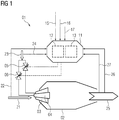
- a combustion device 01 according to the invention is sketched schematically in FIG. This initially comprises the combustion chamber 02 with the main burner 03 arranged thereon and the secondary burner 04. Fuel 23 and supply air 21 can be fed to the burners 03, 04. Exhaust air 25, d. H. Flue gas emerges from the combustion chamber 02.
- control device 11 in which a calculation model 12 is stored and which in this exemplary embodiment includes a data memory 13.
- Various parameters are transmitted to the control device 11.
- the maximum proportion of nitrogen oxides 16 and the maximum proportion of carbon monoxide 17 are fixedly predefined. This can be the respective permissible limit value or the target value.
- the target value can be calculated by the control device. It is also possible to transmit both the permissible limit value and the respective target value as a specification to the control device 11.
- the type or quality 24 of the fuel 23 is known in the calculation model. For this purpose, it is provided, for example, that this 24 is continuously recorded and transmitted to the control device 11. In addition, it is provided in this exemplary embodiment that the temperature and the air humidity 22 of the supply air 21 are measured and transmitted to the control device 11.
- the method according to the invention is triggered by a signal for starting a minimum output, for which purpose the control device 11 is transmitted the respectively required target output 15.
- the minimum fuel supply and, in this case, the optimal distribution between the main burner 03 and the secondary burner 04 are calculated.
- a correspondingly associated main valve 05 for controlling the fuel flow to the main burner 03 and a correspondingly associated secondary valve 06 for controlling the fuel flow to the secondary burner 04 are actuated by the control device 11.
- the target value for carbon monoxide in the calculation has already been reached, while even a greater difference between the target value for nitrogen oxides and the measured value of NOx is present.
- this leads to for advantageous method to change the fuel split, so that also between the target value for carbon monoxide and the calculated value of a difference results, wherein herewith a reduction of the difference between the target value for nitrogen oxides and the measured value of NOx is accompanied - see time T3.
- the amount of fuel can be reduced again until the target values NOx max are essentially reached in accordance with the calculation or the respective measurement - see point in time T4.
- the process stabilizes, in which the proportion of pollutants is reduced over the course of time - see point in time T5. Due to the ongoing monitoring of at least one pollutant, it is possible to trigger a new calculation if the difference arises, so that a renewed lowering of the fuel supply and thus the power P is possible - see time T6.
Landscapes
- Engineering & Computer Science (AREA)
- Chemical & Material Sciences (AREA)
- Combustion & Propulsion (AREA)
- Mechanical Engineering (AREA)
- General Engineering & Computer Science (AREA)
- Regulation And Control Of Combustion (AREA)
Priority Applications (5)
| Application Number | Priority Date | Filing Date | Title |
|---|---|---|---|
| EP20157640.2A EP3865773A1 (fr) | 2020-02-17 | 2020-02-17 | Procédé de commande d'un dispositif de combustion |
| CN202080096776.1A CN115135930B (zh) | 2020-02-17 | 2020-10-16 | 用于控制燃烧装置的方法 |
| EP20797405.6A EP4045851B1 (fr) | 2020-02-17 | 2020-10-16 | Procédé de commande d'un dispositif de combustion |
| US17/792,049 US12553606B2 (en) | 2020-02-17 | 2020-10-16 | Method for controlling a combustion device |
| PCT/EP2020/079142 WO2021164897A1 (fr) | 2020-02-17 | 2020-10-16 | Procédé de commande d'un dispositif de combustion |
Applications Claiming Priority (1)
| Application Number | Priority Date | Filing Date | Title |
|---|---|---|---|
| EP20157640.2A EP3865773A1 (fr) | 2020-02-17 | 2020-02-17 | Procédé de commande d'un dispositif de combustion |
Publications (1)
| Publication Number | Publication Date |
|---|---|
| EP3865773A1 true EP3865773A1 (fr) | 2021-08-18 |
Family
ID=69631435
Family Applications (2)
| Application Number | Title | Priority Date | Filing Date |
|---|---|---|---|
| EP20157640.2A Withdrawn EP3865773A1 (fr) | 2020-02-17 | 2020-02-17 | Procédé de commande d'un dispositif de combustion |
| EP20797405.6A Active EP4045851B1 (fr) | 2020-02-17 | 2020-10-16 | Procédé de commande d'un dispositif de combustion |
Family Applications After (1)
| Application Number | Title | Priority Date | Filing Date |
|---|---|---|---|
| EP20797405.6A Active EP4045851B1 (fr) | 2020-02-17 | 2020-10-16 | Procédé de commande d'un dispositif de combustion |
Country Status (4)
| Country | Link |
|---|---|
| US (1) | US12553606B2 (fr) |
| EP (2) | EP3865773A1 (fr) |
| CN (1) | CN115135930B (fr) |
| WO (1) | WO2021164897A1 (fr) |
Citations (3)
| Publication number | Priority date | Publication date | Assignee | Title |
|---|---|---|---|---|
| US4735052A (en) * | 1985-09-30 | 1988-04-05 | Kabushiki Kaisha Toshiba | Gas turbine apparatus |
| US20110265487A1 (en) * | 2010-04-30 | 2011-11-03 | Alstom Technology Ltd. | Dynamically Auto-Tuning a Gas Turbine Engine |
| WO2013061301A1 (fr) * | 2011-10-26 | 2013-05-02 | Ansaldo Energia S.P.A. | Installation de turbine à gaz pour la production d'énergie électrique et procédé d'exploitation de ladite installation de turbine à gaz |
Family Cites Families (10)
| Publication number | Priority date | Publication date | Assignee | Title |
|---|---|---|---|---|
| EP1533569B1 (fr) | 2003-11-20 | 2016-02-17 | Alstom Technology Ltd | Méthode de fonctionnement d'un appareil de combustion |
| EP1645804A1 (fr) * | 2004-10-11 | 2006-04-12 | Siemens Aktiengesellschaft | Méthode opératoire d'un brûleur, en particulier d'un brûleur de turbine à gaz, et dispositif pour mettre en oeuvre la méthode |
| EP1724528A1 (fr) | 2005-05-13 | 2006-11-22 | Siemens Aktiengesellschaft | Procédé et dispositif de régulation du fonctionnement dans une chambre de combustion d'une turbine à gaz |
| EP1944547A1 (fr) * | 2007-01-15 | 2008-07-16 | Siemens Aktiengesellschaft | Procédé de contrôle d'une fuite de carburant |
| US20090056413A1 (en) * | 2007-09-05 | 2009-03-05 | General Electric Company | Method And System For Predicting Gas Turbine Emissions Utilizing Meteorological Data |
| US9671797B2 (en) * | 2009-05-08 | 2017-06-06 | Gas Turbine Efficiency Sweden Ab | Optimization of gas turbine combustion systems low load performance on simple cycle and heat recovery steam generator applications |
| DE102013202984A1 (de) | 2013-02-22 | 2014-08-28 | Siemens Aktiengesellschaft | Verfahren zum Betreiben einer Gasturbine unterhalb ihrer Nennleistung |
| AT515821A1 (de) * | 2014-05-23 | 2015-12-15 | M A L Umwelttechnik Gmbh | Einspritzvorrichtung, System und Verfahren zur Rauchgasentstickung |
| US10094569B2 (en) * | 2014-12-11 | 2018-10-09 | General Electric Company | Injecting apparatus with reheat combustor and turbomachine |
| EP3130852A1 (fr) * | 2015-08-08 | 2017-02-15 | Testo AG | Procede de reglage d'une installation de chauffage, appareil de mesure de gaz d'echappement et systeme de reglage |
-
2020
- 2020-02-17 EP EP20157640.2A patent/EP3865773A1/fr not_active Withdrawn
- 2020-10-16 EP EP20797405.6A patent/EP4045851B1/fr active Active
- 2020-10-16 CN CN202080096776.1A patent/CN115135930B/zh active Active
- 2020-10-16 US US17/792,049 patent/US12553606B2/en active Active
- 2020-10-16 WO PCT/EP2020/079142 patent/WO2021164897A1/fr not_active Ceased
Patent Citations (3)
| Publication number | Priority date | Publication date | Assignee | Title |
|---|---|---|---|---|
| US4735052A (en) * | 1985-09-30 | 1988-04-05 | Kabushiki Kaisha Toshiba | Gas turbine apparatus |
| US20110265487A1 (en) * | 2010-04-30 | 2011-11-03 | Alstom Technology Ltd. | Dynamically Auto-Tuning a Gas Turbine Engine |
| WO2013061301A1 (fr) * | 2011-10-26 | 2013-05-02 | Ansaldo Energia S.P.A. | Installation de turbine à gaz pour la production d'énergie électrique et procédé d'exploitation de ladite installation de turbine à gaz |
Also Published As
| Publication number | Publication date |
|---|---|
| US20230046593A1 (en) | 2023-02-16 |
| EP4045851C0 (fr) | 2024-02-28 |
| CN115135930A (zh) | 2022-09-30 |
| EP4045851A1 (fr) | 2022-08-24 |
| EP4045851B1 (fr) | 2024-02-28 |
| CN115135930B (zh) | 2025-10-17 |
| WO2021164897A1 (fr) | 2021-08-26 |
| US12553606B2 (en) | 2026-02-17 |
Similar Documents
| Publication | Publication Date | Title |
|---|---|---|
| DE102011085115B4 (de) | Verfahren und Vorrichtung zur Adaption einer Lambdaregelung | |
| DE602004004990T2 (de) | Verfahren zur Verschlechterungsfeststellung eines Abgasreinigers | |
| EP3312405B1 (fr) | Procédé de fonctionnement d'un dispositif d'entraînement et dispositif d'entraînement correspondant | |
| DE102011088296A1 (de) | Verfahren und Vorrichtung zur Dynamiküberwachung von Gas-Sensoren | |
| DE2730100C2 (de) | Einrichtung zum Regeln des Luft/Kraftstoff-Verhältnisses des Betriebsgemisches einer Brennkraftmaschine | |
| DE102004036911A1 (de) | Betriebsverfahren für eine Feuerungsanlage | |
| DE102005032456A1 (de) | Verfahren zur Dynamikdiagnose einer Abgassonde | |
| DE2609161A1 (de) | Regelsystem fuer das luft/kraftstoff- verhaeltnis eines verbrennungsmotors | |
| DE4125154A1 (de) | Verfahren und einrichtung zur lambdasonden-ueberwachung bei einer brennkraftmaschine | |
| DE102005000978B4 (de) | Vorrichtung zur Steuerung des Schadstoffausstoßes eines selbstzündenden Verbrennungsmotors | |
| EP4045851B1 (fr) | Procédé de commande d'un dispositif de combustion | |
| EP1533569B1 (fr) | Méthode de fonctionnement d'un appareil de combustion | |
| DE102011121099B4 (de) | Verfahren zum Betreiben einer Abgasreinigungseinrichtung sowie entsprechende Abgasreinigunseinrichtung | |
| EP3767174B1 (fr) | Procédé et dispositif d'étalonnage ultérieur d'un système de mesure permettant de réguler un mélange gaz-air de combustion dans un appareil de chauffage | |
| EP0416197A1 (fr) | Méthode et dispositif pour améliorer la composition des gaz d'échappement d'un moteur à combustion interne | |
| DE102004017886B3 (de) | Verfahren und Vorrichtung zur Lambdaregelung einer Brennkraftmaschine mit Abgaskatalysator | |
| DE102009054935A1 (de) | Verfahren und Vorrichtung zur Diagnose der Dynamik eines Abgassensors | |
| DE112019000330B4 (de) | Steuervorrichtung für eine gasturbine, gasturbine und verfahren zum steuern einer gasturbine | |
| EP1971804B1 (fr) | Procédé de fonctionnement d'un foyer | |
| EP0655583B1 (fr) | Procédé pour le réglage et la surveillance de combustion | |
| WO2023052453A1 (fr) | Procédé permettant de faire fonctionner un dispositif d'entraînement et dispositif d'entraînement correspondant | |
| DE102025106311B3 (de) | Verfahren zur Regelung eines Verbrennungsluftverhältnisses einer Brennkraftmaschine sowie Steuergerät | |
| DE4103840A1 (de) | Fehler-ueberwachungsverfahren | |
| DE102012207639A1 (de) | Verfahren und Vorrichtung zur Dynamik-Diagnose einer Abgassonde | |
| DE102014002037A1 (de) | NO2 Sichtbarkeitsregelung für passiv regenerierende DPF Systeme |
Legal Events
| Date | Code | Title | Description |
|---|---|---|---|
| PUAI | Public reference made under article 153(3) epc to a published international application that has entered the european phase |
Free format text: ORIGINAL CODE: 0009012 |
|
| STAA | Information on the status of an ep patent application or granted ep patent |
Free format text: STATUS: THE APPLICATION HAS BEEN PUBLISHED |
|
| AK | Designated contracting states |
Kind code of ref document: A1 Designated state(s): AL AT BE BG CH CY CZ DE DK EE ES FI FR GB GR HR HU IE IS IT LI LT LU LV MC MK MT NL NO PL PT RO RS SE SI SK SM TR |
|
| STAA | Information on the status of an ep patent application or granted ep patent |
Free format text: STATUS: THE APPLICATION IS DEEMED TO BE WITHDRAWN |
|
| 18D | Application deemed to be withdrawn |
Effective date: 20220219 |