EP3865960B1 - Computing system for analyzing factory, and method for using computing system in order to manage factory - Google Patents
Computing system for analyzing factory, and method for using computing system in order to manage factory Download PDFInfo
- Publication number
- EP3865960B1 EP3865960B1 EP19870652.5A EP19870652A EP3865960B1 EP 3865960 B1 EP3865960 B1 EP 3865960B1 EP 19870652 A EP19870652 A EP 19870652A EP 3865960 B1 EP3865960 B1 EP 3865960B1
- Authority
- EP
- European Patent Office
- Prior art keywords
- data
- factory
- product
- facilities
- computing system
- Prior art date
- Legal status (The legal status is an assumption and is not a legal conclusion. Google has not performed a legal analysis and makes no representation as to the accuracy of the status listed.)
- Active
Links
Images


Classifications
-
- G—PHYSICS
- G05—CONTROLLING; REGULATING
- G05B—CONTROL OR REGULATING SYSTEMS IN GENERAL; FUNCTIONAL ELEMENTS OF SUCH SYSTEMS; MONITORING OR TESTING ARRANGEMENTS FOR SUCH SYSTEMS OR ELEMENTS
- G05B19/00—Program-control systems
- G05B19/02—Program-control systems electric
- G05B19/18—Numerical control [NC], i.e. automatically operating machines, in particular machine tools, e.g. in a manufacturing environment, so as to execute positioning, movement or co-ordinated operations by means of program data in numerical form
- G05B19/408—Numerical control [NC], i.e. automatically operating machines, in particular machine tools, e.g. in a manufacturing environment, so as to execute positioning, movement or co-ordinated operations by means of program data in numerical form characterised by data handling or data format, e.g. reading, buffering or conversion of data
-
- G—PHYSICS
- G05—CONTROLLING; REGULATING
- G05B—CONTROL OR REGULATING SYSTEMS IN GENERAL; FUNCTIONAL ELEMENTS OF SUCH SYSTEMS; MONITORING OR TESTING ARRANGEMENTS FOR SUCH SYSTEMS OR ELEMENTS
- G05B19/00—Program-control systems
- G05B19/02—Program-control systems electric
- G05B19/418—Total factory control, i.e. centrally controlling a plurality of machines, e.g. direct or distributed numerical control [DNC], flexible manufacturing systems [FMS], integrated manufacturing systems [IMS] or computer integrated manufacturing [CIM]
- G05B19/4183—Total factory control, i.e. centrally controlling a plurality of machines, e.g. direct or distributed numerical control [DNC], flexible manufacturing systems [FMS], integrated manufacturing systems [IMS] or computer integrated manufacturing [CIM] characterised by data acquisition, e.g. workpiece identification
-
- G—PHYSICS
- G05—CONTROLLING; REGULATING
- G05B—CONTROL OR REGULATING SYSTEMS IN GENERAL; FUNCTIONAL ELEMENTS OF SUCH SYSTEMS; MONITORING OR TESTING ARRANGEMENTS FOR SUCH SYSTEMS OR ELEMENTS
- G05B19/00—Program-control systems
- G05B19/02—Program-control systems electric
- G05B19/418—Total factory control, i.e. centrally controlling a plurality of machines, e.g. direct or distributed numerical control [DNC], flexible manufacturing systems [FMS], integrated manufacturing systems [IMS] or computer integrated manufacturing [CIM]
- G05B19/41845—Total factory control, i.e. centrally controlling a plurality of machines, e.g. direct or distributed numerical control [DNC], flexible manufacturing systems [FMS], integrated manufacturing systems [IMS] or computer integrated manufacturing [CIM] characterised by system universality, reconfigurability, modularity
-
- G—PHYSICS
- G05—CONTROLLING; REGULATING
- G05B—CONTROL OR REGULATING SYSTEMS IN GENERAL; FUNCTIONAL ELEMENTS OF SUCH SYSTEMS; MONITORING OR TESTING ARRANGEMENTS FOR SUCH SYSTEMS OR ELEMENTS
- G05B19/00—Program-control systems
- G05B19/02—Program-control systems electric
- G05B19/418—Total factory control, i.e. centrally controlling a plurality of machines, e.g. direct or distributed numerical control [DNC], flexible manufacturing systems [FMS], integrated manufacturing systems [IMS] or computer integrated manufacturing [CIM]
- G05B19/41885—Total factory control, i.e. centrally controlling a plurality of machines, e.g. direct or distributed numerical control [DNC], flexible manufacturing systems [FMS], integrated manufacturing systems [IMS] or computer integrated manufacturing [CIM] characterised by modeling, simulation of the manufacturing system
-
- G—PHYSICS
- G06—COMPUTING OR CALCULATING; COUNTING
- G06Q—INFORMATION AND COMMUNICATION TECHNOLOGY [ICT] SPECIALLY ADAPTED FOR ADMINISTRATIVE, COMMERCIAL, FINANCIAL, MANAGERIAL OR SUPERVISORY PURPOSES; SYSTEMS OR METHODS SPECIALLY ADAPTED FOR ADMINISTRATIVE, COMMERCIAL, FINANCIAL, MANAGERIAL OR SUPERVISORY PURPOSES, NOT OTHERWISE PROVIDED FOR
- G06Q10/00—Administration; Management
- G06Q10/06—Resources, workflows, human or project management; Enterprise or organisation planning; Enterprise or organisation modelling
- G06Q10/063—Operations research, analysis or management
- G06Q10/0633—Workflow analysis
-
- G—PHYSICS
- G06—COMPUTING OR CALCULATING; COUNTING
- G06Q—INFORMATION AND COMMUNICATION TECHNOLOGY [ICT] SPECIALLY ADAPTED FOR ADMINISTRATIVE, COMMERCIAL, FINANCIAL, MANAGERIAL OR SUPERVISORY PURPOSES; SYSTEMS OR METHODS SPECIALLY ADAPTED FOR ADMINISTRATIVE, COMMERCIAL, FINANCIAL, MANAGERIAL OR SUPERVISORY PURPOSES, NOT OTHERWISE PROVIDED FOR
- G06Q10/00—Administration; Management
- G06Q10/06—Resources, workflows, human or project management; Enterprise or organisation planning; Enterprise or organisation modelling
- G06Q10/067—Enterprise or organisation modelling
-
- G—PHYSICS
- G06—COMPUTING OR CALCULATING; COUNTING
- G06Q—INFORMATION AND COMMUNICATION TECHNOLOGY [ICT] SPECIALLY ADAPTED FOR ADMINISTRATIVE, COMMERCIAL, FINANCIAL, MANAGERIAL OR SUPERVISORY PURPOSES; SYSTEMS OR METHODS SPECIALLY ADAPTED FOR ADMINISTRATIVE, COMMERCIAL, FINANCIAL, MANAGERIAL OR SUPERVISORY PURPOSES, NOT OTHERWISE PROVIDED FOR
- G06Q10/00—Administration; Management
- G06Q10/20—Administration of product repair or maintenance
-
- G—PHYSICS
- G06—COMPUTING OR CALCULATING; COUNTING
- G06Q—INFORMATION AND COMMUNICATION TECHNOLOGY [ICT] SPECIALLY ADAPTED FOR ADMINISTRATIVE, COMMERCIAL, FINANCIAL, MANAGERIAL OR SUPERVISORY PURPOSES; SYSTEMS OR METHODS SPECIALLY ADAPTED FOR ADMINISTRATIVE, COMMERCIAL, FINANCIAL, MANAGERIAL OR SUPERVISORY PURPOSES, NOT OTHERWISE PROVIDED FOR
- G06Q50/00—Information and communication technology [ICT] specially adapted for implementation of business processes of specific business sectors, e.g. utilities or tourism
- G06Q50/04—Manufacturing
-
- G—PHYSICS
- G06—COMPUTING OR CALCULATING; COUNTING
- G06T—IMAGE DATA PROCESSING OR GENERATION, IN GENERAL
- G06T7/00—Image analysis
- G06T7/0002—Inspection of images, e.g. flaw detection
- G06T7/0004—Industrial image inspection
-
- G—PHYSICS
- G07—CHECKING-DEVICES
- G07C—TIME OR ATTENDANCE REGISTERS; REGISTERING OR INDICATING THE WORKING OF MACHINES; GENERATING RANDOM NUMBERS; VOTING OR LOTTERY APPARATUS; ARRANGEMENTS, SYSTEMS OR APPARATUS FOR CHECKING NOT PROVIDED FOR ELSEWHERE
- G07C3/00—Registering or indicating the condition or the working of machines or other apparatus, other than vehicles
- G07C3/005—Registering or indicating the condition or the working of machines or other apparatus, other than vehicles during manufacturing process
-
- G—PHYSICS
- G05—CONTROLLING; REGULATING
- G05B—CONTROL OR REGULATING SYSTEMS IN GENERAL; FUNCTIONAL ELEMENTS OF SUCH SYSTEMS; MONITORING OR TESTING ARRANGEMENTS FOR SUCH SYSTEMS OR ELEMENTS
- G05B19/00—Program-control systems
- G05B19/02—Program-control systems electric
- G05B19/418—Total factory control, i.e. centrally controlling a plurality of machines, e.g. direct or distributed numerical control [DNC], flexible manufacturing systems [FMS], integrated manufacturing systems [IMS] or computer integrated manufacturing [CIM]
- G05B19/4184—Total factory control, i.e. centrally controlling a plurality of machines, e.g. direct or distributed numerical control [DNC], flexible manufacturing systems [FMS], integrated manufacturing systems [IMS] or computer integrated manufacturing [CIM] characterised by fault tolerance, reliability of production system
-
- G—PHYSICS
- G05—CONTROLLING; REGULATING
- G05B—CONTROL OR REGULATING SYSTEMS IN GENERAL; FUNCTIONAL ELEMENTS OF SUCH SYSTEMS; MONITORING OR TESTING ARRANGEMENTS FOR SUCH SYSTEMS OR ELEMENTS
- G05B2219/00—Program-control systems
- G05B2219/30—Nc systems
- G05B2219/32—Operator till task planning
- G05B2219/32339—Object oriented modeling, design, analysis, implementation, simulation language
-
- G—PHYSICS
- G05—CONTROLLING; REGULATING
- G05B—CONTROL OR REGULATING SYSTEMS IN GENERAL; FUNCTIONAL ELEMENTS OF SUCH SYSTEMS; MONITORING OR TESTING ARRANGEMENTS FOR SUCH SYSTEMS OR ELEMENTS
- G05B2219/00—Program-control systems
- G05B2219/30—Nc systems
- G05B2219/32—Operator till task planning
- G05B2219/32347—Knowledge based simulation engine, use answers from user, database
-
- G—PHYSICS
- G06—COMPUTING OR CALCULATING; COUNTING
- G06T—IMAGE DATA PROCESSING OR GENERATION, IN GENERAL
- G06T2207/00—Indexing scheme for image analysis or image enhancement
- G06T2207/30—Subject of image; Context of image processing
- G06T2207/30108—Industrial image inspection
- G06T2207/30164—Workpiece; Machine component
Definitions
- the present disclosure relates to a computing system, and more particularly, relates to a computing system for analyzing a factory and a method of using the computing system to manage the factory.
- Factory automation refers to automatize overall procedures for control, management, and operation of a factory producing products by using robots, computers, and the like.
- IT information technology
- the smart factory is an intelligent factory capable of improving productivity of a factory and a product quality by applying information and communication technologies to overall processes that are performed in the factory.
- the virtual factory may be implemented in a virtual environment based on a result of modeling a real factory.
- a process that is performed in the real factory is modeled so as to be expressed by a factory model implemented in the virtual environment. Accordingly, as the virtual factory is used, even though a product is not really produced in the real factory, procedures for producing products may be virtually implemented or duplicated through simulation in the virtual environment.
- EP 2755096 A1 describes an imaging device and terminal device for each of plural work areas. Image data sets, capturing time data sets, and imaging unit identifiers transmitted by imaging device are stored in association with each other in an image database.
- WO 2008/116282 A1 describes a method and system for identifying, quantifying and presenting to a user constraints in an automated manufacturing or processing facility.
- a data processing system continuously receives basic status signals and state signals from automation equipment in the facility and evaluates and processes these signals to derive a throughput capability measure (a measure of constraint) of each given manufacturing workstation in the process.
- An object of the present disclosure is directed to provide a computing system for building a virtual factory reflecting a situation of a real factory and analyzing the situation of the real factory and a method of managing the real factory by using the computing system.
- a computing system for building a virtual factory as recited in claim 1.
- the present disclosure may gather data associated with a real factory from the real factory.
- a monitoring device may be installed on a facility to gather data associated with the facility. Also, the monitoring device may be installed in a surrounding area adjacent to the facility to gather data associated with both the facility and a process.
- the present disclosure may analyze and predict a situation of a real factory in real time by using data gathered from the real factory.
- the user may establish a producing plan capable of increasing the production of a factory with reference to the analysis result and the prediction result. Also, the user may manage works performed in a factory and products generated in the factory in an optimum state with reference to the analysis result and the prediction result.
- the present disclosure builds a virtual factory, to which a situation of a real factory is reflected, by using data gathered from the real factory. Accordingly, a situation of a real factory may be displayed at a look in real time.
- the present disclosure may build a virtual factory on a cloud and may analyze a situation of a real factory. Accordingly, according to an embodiment of the present disclosure, users may access the virtual factory through a plurality of servers and may check a result of analyzing a situation of a real factory.
- FIG. 1 is a conceptual diagram illustrating a real factory and an image displayed in a display panel of the present disclosure.
- a real factory 1000 may be a physical work space that is used to produce, process, and/or pack any object or product.
- the real factory 1000 may include facilities 311, 312, and 313, a vehicle 325, products 331a, 332a, 333a, and 334a, transport containers 331, 332, 333, and 334, and workers 341 and 342.
- the real factory 1000 is illustrated by ways of example for better understanding of the present disclosure, and the present disclosure is not limited thereto.
- the real factory 1000 may include one or more facilities, one or more vehicles, one or more transport containers, and one or more workers and may further include components for operating the real factory 1000.
- the products 331a, 332a, 333a, and 334a may be produced and managed by the workers 341 and 342, the facilities 311, 312, and 313, the vehicle 325, and the transport containers 331, 332, 333, and 334.
- the product 331a may be produced by the facilities 311, 312, and 313.
- the products 331a, 332a, 333a, and 334a may be kept or carried in a state of being put in the transport containers 331, 332, 333, and 334.
- work used in the specification means one operation that is performed by the workers 341 and 342, the facilities 311, 312, and 313, and the vehicle 325 in the real factory 1000.
- one work may be to move the product 332a by using the vehicle 325.
- process used in the specification means a series of works that are performed to produce one product.
- one process may be composed of one or more works of the following: a work for producing the product 332a by using the facilities 311, 312, and 313, a work for putting the product 332a in the transport container 332, and a work for transporting the product 332a by using the vehicle 325.
- data associated with a real factory used in the specification means data gathered from the real factory 1000.
- the data associated with the real factory may include data that are measured or observed (or monitored) from the facilities 311, 312, and 313, the vehicle 325, the products 331a, 332a, 333a, and 334a, the transport containers 331, 332, 333, and 334, and the workers 341 and 342.
- situation of a real factory used in the specification means a "structure of a real factory” and a "progress situation of a work being performed in a real factory".
- the structure of the real factory means locations of the facilities 311, 312, and 313, the vehicle 325, the transport containers 331, 332, 333, and 334, and the workers 341 and 342 in the real factory 1000.
- the progress situation of the work being performed in the real factory means whether the facilities 311, 312, and 313 normally operate, how much products are produced, and the like.
- the present disclosure may gather data associated with the real factory 1000 from the real factory 1000 and builds a virtual factory, to which a situation of the real factory 1000 is reflected, by using the data associated with the real factory 1000. Also, the present disclosure may analyze a situation of the real factory 1000 by using the data associated with the real factory 1000.
- the present disclosure may display a two-dimensional (2D) image and/or a three-dimensional (3D) image of an analysis result 2200, which is obtained by analyzing the situation of the real factory 1000, and a virtual factory 2100 in a display panel 2000. Accordingly, a user may manage the real factory 1000 with reference to the virtual factory 2100 and the analysis result 2200 displayed in the display panel 2000. With reference to the virtual factory 2100 and the analysis result 2200, the user may establish a producing plan capable of making productivity of the real factory 1000 high.
- the real factory 1000, the virtual factory 2100, and the analysis result 2200 will be described in more detail with reference to FIGS. 2 to 13 .
- FIG. 2 is a block diagram illustrating a device and a system used to manage a real factory of FIG. 1 .
- a data gathering device 100 may include a data gathering device for equipment 110, a data gathering device for vehicle 120, a data gathering device for container 130, a data gathering device for worker 140, and a data gathering device for factory 150.
- the data gathering devices 110, 120, 130, 140 and 150 may gather data d01, d02, d03, d04, and d05 associated with the real factory 1000 from the real factory 1000.
- the data gathering devices 110, 120, 130, 140, and 150 and the data d01, d02, d03, d04, and d05 will be described in detail with reference to FIGS. 4 to 6 .
- the data gathering devices 110, 120, 130, 140, and 150 may respectively output the data d01, d02, d03, d04, and d05 to a middleware system 200 through interfaces 111, 121, 131, 141, and 151.
- that devices and modules output and/or receive data may be used but may mean that real devices and modules output and/or receive signals including data.
- a "module” may be implemented with a hardware circuit (e.g., an analog circuit and a logic circuit) configured to perform given and/or reconfigurable operations and functions.
- a “module” may be implemented by a program code of software configured to perform given and/or programmable operations and functions, and an instruction set of the program code may be executed by a processing device (e.g., a central processing unit (CPU) or a graphic processing unit (GPU)).
- a “module” may be implemented in a hybrid form of hardware and software.
- the middleware system 200 may include interfaces 210 and 230 and a data processing module 220.
- the data gathering device 100 and a computing system 300 may communicate with each other through the middleware system 200.
- the middleware system 200 may use a communication technology such as TCP/IP (Transmission Control Protocol/Internet Protocol), database access middleware, DCOM (Distributed Component Object Model), CORBA (Common Object Request Broker Architecture), Bluetooth, 3G, 4G, 5G, Wi-Fi (Wireless Fidelity), or the like.
- the middleware system 200 may receive the data d01, d02, d03, d04, and d05 through the interface 210.
- the data processing module 220 may receive the data d01, d02, d03, d04, and d05 from the interface 210.
- the data processing module 220 may process the data d01, d02, d03, d04, and d05 to generate data d1.
- the data d1 includes information for analyzing the real factory 1000.
- the data d01 includes information about an image taken by the data gathering device for equipment 110.
- the data processing module 220 calculates a processing time taken to perform a work in the real factory 1000, by using the data d01.
- the data d1 may include information about a processing time.
- the data d01, d02, d03, d04, and d05 and the data d1 will be described in detail with reference to FIGS. 3 to 6 .
- the amount of data to be transmitted to the computing system 300 may decrease. This may mean that the amount of data to be processed by the computing system 300 decreases. The decrease in the amount of data to be processed by the computing system 300 may also improve a speed at which the computing system 300 processes data.
- the data processing module 220 may output the data d1 to the interface 230.
- the middleware system 200 may output the data d1 to the computing system 300 through the interface 230.
- the computing system 300 includes an interface 310, database 320, a modeling module 330, a virtual factory building module 340, a display device 350, and a data analysis module 360.
- the computing system 300 may further include a processing (or computing) device configured to execute an instruction set of a program code for some operations and functions, which is implemented by software, and a memory for storing data to be used by the processing device.
- a processing (or computing) device configured to execute an instruction set of a program code for some operations and functions, which is implemented by software, and a memory for storing data to be used by the processing device.
- the computing system 300 may receive the data d1 through the interface 310.
- the computing system 300 builds the virtual factory 2100, to which a situation of the real factory 1000 is reflected, by using the data d1 and analyzes the situation of the real factory 1000.
- the computing system 300 may be connected with the data gathering device 100 through a short range network or a long range network.
- the middleware system 200 may arbitrate communication between the data gathering device 100 and the computing system 300 on a network and may perform appropriate data processing for the computing system 300 by using the data processing module 220.
- the computing system 300 may be implemented within the real factory 1000 and may be directly accessed by the user present in the real factory 1000.
- all or a part of components of the computing system 300 may be separated from the real factory 1000 and may be remotely accessed by users present in the real factory 1000.
- the middleware system 200 may be separated from the computing system 300 and may be implemented inside or outside the real factory 1000.
- the computing system 300 may build the virtual factory 2100 that is driven in a cloud environment and may analyze a situation of the real factory 1000.
- the computing system 300 may use AWS (Amazon Web Service), Microsoft Azure, or the like, or the computing system 300 may automatically build and use a cloud server or a web server. Accordingly, users may access the virtual factory 2100 through one or more servers and may check a result of analyzing a situation of the real factory 1000 by accessing the virtual factory 2100.
- AWS Amazon Web Service
- Azure Microsoft Azure
- users may access the virtual factory 2100 through one or more servers and may check a result of analyzing a situation of the real factory 1000 by accessing the virtual factory 2100.
- the display device 350 may display a 2D image and/or a 3D image of the analysis result 2200, which is obtained by analyzing the situation of the real factory 1000, and the virtual factory 2100 in the display panel 2000 as illustrated in FIG. 1 .
- the database 320 may store data such as a location and a size of each facility, the number of workers, and kinds of processes to be performed in a factory.
- the database 320 may store data that are input in advance by the user. For example, to build a virtual factory, the user may input data to the database 320 before operating a computing system. For another example, before the data gathering device 100 gathers the data d01, d02, d03, d04, and d05 from the real factory 1000, the user may input data to the database 320.
- the database 320 may store data indicating a situation of the real factory 1000.
- the database 320 may receive data d2 from the interface 310 and may store the data d2.
- the modeling module 330 may generate modeling data by using data stored in the database 320.
- the modeling module 330 may include a 2D, 3D modeling program and QUEST, such as Auto CAD, 3D MAX, or Pro-E, a simulation program such as eM-Plant or ARENA, or the like.
- the modeling module 330 may generate modeling data associated with facilities, vehicles, products, workers, processes, and factories by using 3D computer aided design (CAD) information of facilities, vehicles, products, and workers.
- the modeling data may include information for displaying a configuration corresponding to the modeling data in the display panel 2000 in the shape of a 2D and/or 3D model.
- the computing system 300 may display a 2D and/or 3D facility model in the display panel 2000 by using the facility modeling data.
- the database 320 may store the generated modeling data.
- the virtual factory building module 340 may receive the data d2 from the interface 310.
- the data d2 may include a part of information included in the data d1.
- the data d2 may include information about a size and a location of each facility, speeds of vehicles, speeds of transport containers, the number of workers, and the number and kinds of processes.
- the virtual factory building module 340 builds the virtual factory 2100, to which a situation of the real factory 1000 is reflected, by using the data d2.
- the virtual factory building module 340 detects modeling data corresponding to the data d2 from the database 320.
- the case where the database 320 generates modeling data in real time by using the data d2 will be described in detail with reference to FIG. 13 .
- the virtual factory building module 340 may generate data d3 by using the data d2 and the modeling data.
- the data d3 may include information about the virtual factory 2100 to which a situation of the real factory 1000 is reflected.
- the virtual factory building module 340 may output the data d3 to the display device 350.
- the display device 350 may receive the data d3.
- the display device 350 may display a 2D image and/or a 3D image of the virtual factory 2100 in the display panel 2000 by using the data d3 as illustrated in FIG. 1 .
- the data analysis module 360 may receive data d4 from the interface 310.
- the data d4 may include a part of information included in the data d1.
- the data d4 may include information about a processing time, a mean time to repair (MTTR), and a mean time between failures (MTBF).
- MTTR mean time to repair
- MTBF mean time between failures
- the data analysis module 360 may generate data d5 by using the data d4.
- the data d5 may include information about a result of analyzing a current situation of the real factory 1000 and/or a result of predicting a future situation of the real factory 1000.
- the data analysis module 360 may output the data d5 to the display device 350.
- the display device 350 may receive the data d5.
- the display device 350 may display the current situation of the real factory 1000 and/or the analysis result 2200 of analyzing and predicting the future situation of the real factory 1000 in the display panel 2000 by using the data d5 as illustrated in FIG. 1 .
- FIG. 3 is a conceptual diagram for describing an operation of a data processing module of FIG. 2 .
- the data processing module 220 may generate the data d1 by using the data d01, d02, d03, d04, and d05.
- the data processing module 220 may generate the data d1 by processing a part of information included in the data d01, d02, d03, d04, and d05.
- the data d0 may include the same information as the part of the information included in the data d01, d02, d03, d04, and d05 or may include information obtained by converting the part of the information included in the data d01, d02, d03, d04, and d05.
- FIG. 3 will be described together with FIGS. 4 to 6 .
- FIG. 4 is a conceptual diagram illustrating a data gathering device gathering data from a real factory of FIG. 1 .
- the data gathering device 100 may include the data gathering device for equipment 110, the data gathering device for vehicle 120, the data gathering device for container 130, the data gathering device for worker 140, and the data gathering device for factory 150.
- the data gathering device for vehicle 120, the data gathering device for container 130, and the data gathering device for worker 140 may include a variety of sensors.
- the data gathering device for vehicle 120, the data gathering device for container 130, and the data gathering device for worker 140 may be attached to the vehicle 325, the transport containers 331, 332, 333, and 334, and the workers 341 and 342 by using a magnet or an adhesive material.
- the data gathering device for vehicle 120, the data gathering device for container 130, and the data gathering device for worker 140 may operate based on a power supplied from an external power source or based on powers supplied from batteries respectively included in the data gathering device for vehicle 120, the data gathering device for container 130, and the data gathering device for worker 140.
- the data gathering device for vehicle 120 may gather the data d02 associated with a location, a speed, acceleration, and a movement direction of the vehicle 325, and the intensity of a noise, the intensity of vibration, a temperature, illuminance, and humidity of a place where the vehicle 325 is located, through the sensors.
- the data gathering device for container 130 may gather the data d03 associated with a location of each of the transport containers 331, 332, 333, and 334, and the intensity of a noise, the intensity of vibration, a temperature, illuminance, and humidity of each of places where the transport containers 331, 332, 333, and 334 are located, through the sensors.
- the data gathering device for worker 140 may gather the data d04 associated with a blood pressure and a body temperature of each of the workers 341 and 342, a location of each of the workers 341 and 342, and the intensity of a noise, the intensity of vibration, a temperature, illuminance, and humidity of each of places where the workers 341 and 342 are located, through the sensors.
- the data processing module 220 may calculate the number of workers 341 and 342 by using information about blood pressures of the workers 341 and 342.
- the data d1 may include information about the number of workers 341 and 342, and may include information about speeds of the vehicle 325 and the transport containers 331, 332, 333, and 334.
- the data gathering device for equipment 110 may include a plurality of monitoring devices 110a and 110b.
- the monitoring devices 110a and 110b may monitor a part of the facilities 311 and 313 from the outside of the facilities 311 and 313.
- the facilities 311 and 313 may be used to perform a process.
- the facilities 311 and 313 may be used to perform one work included in the process.
- the monitoring devices 110a and 110b may be installed in the real factory 1000 and components included in the real factory 1000 for the purpose of monitoring a part of the facilities 311 and 313.
- the monitoring devices 110a and 110b may be installed in the facilities 311 and 313, respectively.
- the data gathering device for equipment 110 may be installed in a surrounding area adjacent to facilities. The case where the data gathering device for equipment 110 is installed in a surrounding area adjacent to facilities will be described in detail with reference to FIG. 7 .
- the monitoring devices 110a and 110b may monitor a part of the facilities 311 and 313 and/or one work of a process by taking a part of the facility 311 and a part of the facility 313, respectively.
- the monitoring devices 110a and 110b may be a photographing device such as a digital camera.
- the monitoring devices 110a and 110b may monitor a part of each of the facilities 311 and 313 and/or one work of a process by monitoring the product.
- the monitoring devices 110a and 110b may be a sensor capable of recognizing an object, such as a depth sensor or a vision sensor.
- the monitoring devices 110a and 110b may recognize the data gathering device for container 130 and/or the product 331a.
- the monitoring device 110a recognizes the data gathering device for container 130 attached to the transport container 331 and/or the product 331a.
- the monitoring device 110a outputs a signal.
- the signal includes information indicating that the product 331a is detected at the location P1.
- the signal includes information about an image taken by the monitoring device 110a when the product 331a is at the location P1.
- the monitoring device 110b may recognize the data gathering device for container 130 attached to the transport container 331 and/or the product 331a. In the case where the product 331a is at the location P2, the monitoring device 110b outputs a signal.
- the signal includes information indicating that the product 331a is detected at the location P2.
- the signal includes information about an image taken by the monitoring device 110a when the product 331a is at the location P2.
- Each of the signals output from the monitoring devices 110a and 110b includes time information about a time when the corresponding signal is output.
- the data processing module 220 calculates a time difference between a time at which the signal is output by the monitoring device 110a and a time at which the signal is output by the monitoring device 110b, by using the time information included in the signals. Accordingly, the data processing module 220 may calculate a time taken for the product 331a to move from the location P1 to the location P2.
- each of the monitoring devices 110a and 110b may continuously take the locations P1 and P2.
- Each of the monitoring devices 110a and 110b transmits a signal, which includes information about images obtained by taking the locations P1 and P2, to the data processing module 220 in real time.
- the signal includes information about times at which the images are taken.
- the data processing module 220 may process the signal to obtain time information about times at which the product 331a is taken at the locations P1 and P2.
- the monitoring devices 110a and 110b may be installed at opposite ends of a facility, or may be installed at a start location and an end location of one process, which will be described in detail with reference to FIG. 6 .
- the data gathering device for equipment 110 may include sensors.
- the sensors may be attached to the facilities 311, 312, and 313 to gather data associated with the intensity of a noise, the intensity of vibration, a temperature, illuminance, and humidity of each of places where the facilities 311, 312, and 313 are located.
- the data gathering device for factory 150 may gather data associated with the whole structure of the real factory 1000 and the whole situation of the real factory 1000.
- the data gathering device for factory 150 may monitor the whole appearance of the real factory 1000.
- the data gathering device for factory 150 may be installed on an inner wall of the real factory 1000 to monitor the whole appearance of the real factory 1000.
- the data gathering device for factory 150 may be one of devices such as a digital camera, a depth camera, and a vision sensor.
- the data processing module 220 may calculate a size and a location of each of the facilities 311, 312, and 313 by using an image taken by the data gathering device for factory 150 and/or a signal output from the data gathering device for factory 150.
- the data processing module 220 may calculate kinds, the number, and scales of processes by using the image taken by the data gathering device for factory 150 and/or the signal output from the data gathering device for factory 150.
- FIG. 5 is a conceptual diagram illustrating an image taken by a data gathering device for factory of FIG. 4 .
- the data gathering device for factory 150 may take the whole appearance of the real factory 1000.
- An image 3000 taken by the data gathering device for factory 150 may include information about a structure of the real factory 1000 and the whole situation of the real factory 1000.
- the image 3000 may include information about a size and a location of each of facilities 311, 312, 313, 314, and 315 and offices 351 and 352.
- the data processing module 220 may calculate the size and location of each of the facilities 311, 312, 313, 314, and 315 by using the image 3000.
- the data d1 may include information about the size and location of each of the facilities 311, 312, 313, 314, and 315, instead of the image 3000.
- the data processing module 220 may convert the information about the image 3000 into information about the size and the location of each of the facilities 311, 312, 313, 314, and 315 such that the amount of data d1 output from the data processing module 220 decreases.
- FIG. 6 is a conceptual diagram illustrating an example method of gathering data by monitoring devices of FIG. 4 .
- the data gathering device for equipment 110 may monitor a part of the facilities 311, 312, 313, 314, and 315 by using monitoring devices 111a, 111b, 111c, and 111d. In the case where the facilities 311, 312, 313, 314, and 315 are used in one process, the data gathering device for equipment 110 may monitor one work of the process by using the monitoring devices 111a, 111b, 111c, and 111d.
- the data processing module 220 may calculate a processing time, a mean time to repair (MTTR), and a mean time between failures (MTBF) by using a signal output from the data gathering device for equipment 110.
- the data processing module 220 may convert information included in the signal into information about the processing time, the mean time to repair, and the mean time between failures such that the amount of data d1 output from the data processing module 220 decreases.
- the monitoring devices 111a and 111b may be installed at opposite ends P11 and P12 of the facility 311. While the transport container 331 moves from the location P11 to the location P12, the facility 311 may perform one work.
- the data processing module 220 may calculate a processing time taken for the facility 311 to perform a work, a mean time to repair of the facility 311, and a mean time between failures of the facility 311, by using signals output from the monitoring devices 111a and 111b.
- the monitoring devices 111a and 111c may be respectively installed at ends P11 and P13 of the facilities 311 and 313 as described with reference to FIG. 4 . While the transport container 331 moves from the location P11 to the location P13, the facilities 311, 312, and 313 may perform one work.
- the data processing module 220 may calculate a processing time taken for the facilities 311, 312, and 313 to perform a work, by using signals output from the monitoring devices 111a and 111c.
- the monitoring devices 111a and 111d may be respectively installed at ends P11 and P14 of the facilities 311 and 315. While the transport container 331 moves from the location P11 to the location P14, the facilities 311 to 315 may perform one work.
- the data processing module 220 may calculate a processing time taken for the facilities 311 to 315 to perform a process, by using signals output from the monitoring devices 111a and 111d.
- the data gathering device for equipment 110 may include a plurality of monitoring devices to monitor a product that moves over time.
- a plurality of monitoring devices may be easily be attached or installed to or in facilities. Accordingly, even in the case where a facility incapable of automatically measuring a processing time is used in the real factory 1000, the present disclosure may easily gather data associated with a processing time of a facility by using a plurality of monitoring devices.
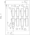
- FIG. 7 is a conceptual diagram illustrating an example method of gathering data by monitoring devices of FIG. 4 .
- One process 1500a may be performed in a factory 1000a illustrated in FIG. 7 .
- Facilities 311a to 314a and 311b to 314b, workers 343 and 344, and vehicles 326 and 327 may be required to perform the process 1500a.
- the process 1500a may include a series of works.
- the works may be performed by the facilities 311a to 314a and 311b to 314b.
- the present disclosure is not limited thereto.
- a plurality of processes may be performed in the factory 1000a, and the process 1500a may be performed by one or more facilities, one or more workers, one or more vehicles, and one or more transport containers.
- the data gathering device for equipment 110 may monitor a work, which is performed by the process 1500a and/or the facilities 311a to 314a and 311b to 314b, by using monitoring devices 111e, 111f, 111g, and 111h.
- the process 1500a may start from the facility 311a and may be completed at the facility 314b.
- the facilities 311a and 314b may include a load device 319a and an unload device 319b, respectively.
- the load device 319a and the unload device 319b may be devices independent of the facilities 311a and 314b.
- the load device 319a may be used to load the product 331a onto the facility 311a.
- the unload device 319b may be used to unload the product 331a from the facility 314b.
- the monitoring devices 111e and 111f may monitor a start portion of the process 1500a and a complete portion of the process 1500a, respectively.
- the monitoring devices 111e and 111f may monitor the load device 319a and the unload device 319b, respectively.
- the monitoring devices 111e and 111f may be installed in surrounding areas adjacent to the facilities 311a and 314b.
- the monitoring devices 111e and 111f may be installed in a surrounding areas adjacent to the load device 319a and a surrounding areas adjacent to the unload device 319b.
- the data processing module 220 may calculate a tact time, a neck time, a cycle time of each process, and a net cycle time of each process, by using signals output from the monitoring devices 111e and 111f.
- the monitoring devices 111g and 111h may correspond to the monitoring devices 110a and 110b illustrated in FIG. 4 .
- the monitoring devices 111g and 111h may be installed in surrounding areas adjacent to the facilities 311a and 311b. Below, the descriptions given above are omitted to avoid redundancy.
- the data gathering device for equipment 110 may gather data associated with process 1500a, as well as data associated with the facilities 311a to 314a and 311b to 314b.
- the present disclosure may obtain an analysis result of high reliability with respect to the process 1500a and the factory 1000a by gathering data associated with the process 1500a independently of the facilities 311a to 314a and 311b to 314b.
- FIG. 8 is a conceptual diagram for describing an operation of a virtual factory building module of FIG. 2 .
- FIG. 9 is a conceptual diagram illustrating a virtual factory displayed in a display panel of FIG. 2 .
- FIGS. 1 , 8 , and 9 will be referenced together.
- the virtual factory building module 340 may receive the data d2 from the interface 310.
- the data d2 may include a part of information included in the data d1.
- the data d2 may include only information necessary to build the virtual factory 2100 from among the information included in the data d1.
- the data d2 may include information about a size, a location, and a processing time of each facility, speeds of vehicles, speeds of transport containers, and the number of workers.
- the virtual factory building module 340 may build the virtual factory 2100, to which a structure and a work situation of the real factory 1000 are reflected, by using the data d2. For example, the virtual factory building module 340 may build the virtual factory 2100 by disposing facility models at the virtual factory 2100 by using the information about the location of each facility included in the data d2.
- the database 320 may store information about the data d2 and/or the built virtual factory 2100.
- the modeling module 330 may support visualization of the virtual factory 2100 based on the information stored in the database 320.
- the display device 350 may provide the user with a visualized shape of the virtual factory 2100 through the display panel 2000.
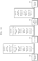
- FIG. 10 is a conceptual diagram for describing an operation of a data analysis module of FIG. 2 .
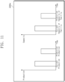
- FIG. 11 is a conceptual diagram illustrating an analysis result of a real factory displayed in a display panel of FIG. 2 .
- FIGS. 1 , 10 , and 11 will be referenced together.
- the data analysis module 360 may receive the data d4 from the interface 310.
- the data d4 may include a part of information included in the data d1.
- the data d4 may include only information necessary to analyze a current situation of the real factory 1000 and to predict a future situation of the real factory 1000 from among the information included in the data d1.
- the data d4 may include information about a processing time, a mean time to repair, a mean time between failures, speeds of vehicles, speeds of transport containers, and the number of workers.
- the data analysis module 360 may generate the data d5 by using the data d4.
- the data d5 may include information that is useful for the user to make a decision about a real factory.
- the data d5 may include information about primary KPIs (Key Performance Indicators) of a factory.
- KPIs Key Performance Indicators
- the data d5 may include information about a result of analyzing a current situation of the real factory 1000 and/or a result of predicting a future situation of the real factory 1000.
- the data analysis module 360 analyzes a progress situation of a first work that is performed while the transport container 331 is moved from the location P11 to the location P13. After the first work starts, a second work starts from the facility 311. The second work may be performed by the facilities 311, 312, and 313. The data analysis module 360 predicts a progress situation of the second work based on the signals output from the monitoring devices 111a and 111c.
- the data d5 may include information about the production of products, an operating state of a facility, a progress situation of a process, and the like.
- the data d5 may include information about a current lead time of a product, a predicted lead time of the product, a current production of the product, a predicted production of the product, a trend in production, a current stock of the product, a predicted stock of the product, a trend in product inventory, a tact time, a neck time, a cycle time for each process, a net cycle time for each process, a current capacity for each process, a predicted capacity for each process, a current work-in-process stock for each process, a predicted work-in-process stock of each process, a current capacity of each facility, predicted operation, congestion, waiting, and failure of each facility, current capacity of each transport device, predicted operation, congestion, waiting, and failure of each transport device, a congestion interval of a current process, and strength of each neck process.
- the information included in the data d5 may be displayed in the display panel 2000.
- the display device 350 may display a current situation of the real factory 1000 and the analysis result 2200 of a future situation of the real factory 1000 through the display panel 2000 in the shape of a graph or a chart.
- the analysis result 2200 may display current production, predicted production of the real factory 1000, a current capacity of a facility, and a predicted capacity of a facility.
- the user may grasp a current situation and a predicted situation of the real factory 1000 with reference to the analysis result 2200 displayed in the display panel 2000. With reference to the analysis result 2200, the user may establish a producing plan capable of optimally maintaining the real factory 1000.
- FIG. 12 is a flowchart for describing a method of displaying a virtual factory and an analysis result of a situation of a real factory in a display panel of FIG. 2 .
- FIG. 2 will be referenced together.
- the data gathering device 100 may gather the data d01, d02, d03, d04, and d05 associated with the real factory 1000.
- the data gathering device 100 may transmit the gathered data d01, d02, d03, d04, and d05 to the middleware system 200.
- the middleware system 200 may receive the gathered data d01, d02, d03, d04, and d05.
- the middleware system 200 may generate the data d1 by processing the gathered data d01, d02, d03, d04, and d05 through the data processing module 220.
- the middleware system 200 may transmit the data d1 to the computing system 300.
- the computing system 300 may receive the data d1.
- the virtual factory building module 340 may receive the data d2.
- the virtual factory building module 340 may generate the data d3 by using the data d2.
- the data d3 may include information about a virtual factory.
- the virtual factory building module 340 may output the data d3 to the display device 350. Operation S450 will be described in detail with reference to FIG. 13 .
- the data analysis module 360 may receive the data d4.
- the data analysis module 360 may generate the data d5 by using the data d4.
- the data d5 may include information about a result of analyzing a situation of a real factory.
- the data analysis module 360 may output the data d5 to the display device 350.
- the display device 350 may receive the data d3 and the data d5.
- the display device 350 may display a 2D image and/or a 3D image of the virtual factory 2100 and the analysis result 2200 of the situation of the real factory 1000 in the display panel 2000 by using the data d3 and d5.
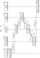
- FIG. 13 is a flowchart for describing a method of building a virtual factory at a virtual factory building module of FIG. 2 .
- Operation S515 to operation S560 illustrated in FIG. 13 correspond to operation S450 described with reference to FIG. 12 .
- the interface 310 may receive the data d1 from the middleware system 200.
- the interface 310 may transmit the data d2 to the virtual factory building module 340 based on the received data d1.
- the interface 310 may transmit the data d2 to the database 320.
- the database 320 may store the data d2.
- the database 320 may transmit the data d2 to the modeling module 330.
- the modeling module 330 may generate modeling data corresponding to the data d2 by using the data d2.
- the modeling module 330 may transmit the modeling data to the database 320.
- the database 320 stores the modeling data.
- the database 320 may store information about a correspondence relationship between the modeling data and the data d2.
- the database 320 may store the modeling data, the data d2, and the information about the correspondence relationship between the modeling data and the data d2.
- the virtual factory building module 340 may detect the modeling data corresponding to the data d2 from the database 320.
- the database 320 may transmit the modeling data to the virtual factory building module 340.
- the virtual factory building module 340 may generate the data d3 by using the data d2 and the modeling data.
- the data d3 may include information about the virtual factory 2100 to which a situation of the real factory 1000 is reflected.
- the virtual factory building module 340 may transmit the data d3 to the display device 350.
- the display device 350 may output a visualized shape of the virtual factory 2100 through the display panel 2000 based on the data d3.
Landscapes
- Engineering & Computer Science (AREA)
- Business, Economics & Management (AREA)
- Human Resources & Organizations (AREA)
- General Physics & Mathematics (AREA)
- Physics & Mathematics (AREA)
- Strategic Management (AREA)
- Manufacturing & Machinery (AREA)
- Economics (AREA)
- Quality & Reliability (AREA)
- Theoretical Computer Science (AREA)
- Entrepreneurship & Innovation (AREA)
- Tourism & Hospitality (AREA)
- General Business, Economics & Management (AREA)
- Marketing (AREA)
- Automation & Control Theory (AREA)
- Operations Research (AREA)
- General Engineering & Computer Science (AREA)
- Educational Administration (AREA)
- Game Theory and Decision Science (AREA)
- Development Economics (AREA)
- Health & Medical Sciences (AREA)
- General Health & Medical Sciences (AREA)
- Primary Health Care (AREA)
- Computer Vision & Pattern Recognition (AREA)
- Human Computer Interaction (AREA)
- General Factory Administration (AREA)
- Management, Administration, Business Operations System, And Electronic Commerce (AREA)
- Testing And Monitoring For Control Systems (AREA)
Applications Claiming Priority (2)
| Application Number | Priority Date | Filing Date | Title |
|---|---|---|---|
| KR1020180119847A KR102086005B1 (ko) | 2018-10-08 | 2018-10-08 | 공장을 분석하는 컴퓨팅 시스템 및 공장을 관리하기 위해 그 컴퓨팅 시스템을 이용하는 방법 |
| PCT/KR2019/013031 WO2020076012A1 (ko) | 2018-10-08 | 2019-10-04 | 공장을 분석하는 컴퓨팅 시스템 및 공장을 관리하기 위해 그 컴퓨팅 시스템을 이용하는 방법 |
Publications (4)
| Publication Number | Publication Date |
|---|---|
| EP3865960A1 EP3865960A1 (en) | 2021-08-18 |
| EP3865960A4 EP3865960A4 (en) | 2021-11-24 |
| EP3865960C0 EP3865960C0 (en) | 2024-07-24 |
| EP3865960B1 true EP3865960B1 (en) | 2024-07-24 |
Family
ID=70163838
Family Applications (1)
| Application Number | Title | Priority Date | Filing Date |
|---|---|---|---|
| EP19870652.5A Active EP3865960B1 (en) | 2018-10-08 | 2019-10-04 | Computing system for analyzing factory, and method for using computing system in order to manage factory |
Country Status (7)
| Country | Link |
|---|---|
| US (1) | US11940783B2 (pl) |
| EP (1) | EP3865960B1 (pl) |
| JP (1) | JP7145339B2 (pl) |
| KR (1) | KR102086005B1 (pl) |
| CN (1) | CN112823317B (pl) |
| PL (1) | PL3865960T3 (pl) |
| WO (1) | WO2020076012A1 (pl) |
Families Citing this family (6)
| Publication number | Priority date | Publication date | Assignee | Title |
|---|---|---|---|---|
| CN116449774B (zh) * | 2022-01-06 | 2025-09-12 | 蜂联智能(深圳)有限公司 | 基于工厂环境虚拟化受力评估的调控方法、调控装置及可读介质 |
| CN114415575B (zh) * | 2022-01-27 | 2023-05-05 | 电子科技大学 | 实时数据驱动的焊接车间三维虚拟监控与智能预警系统 |
| KR102590515B1 (ko) | 2022-11-07 | 2023-10-19 | (주)브이엠에스 솔루션스 | 공장 상황을 나타내는 이미지에 대한 전처리 장치 및 방법 |
| KR102888767B1 (ko) * | 2022-12-09 | 2025-11-21 | 주식회사 쓰리디오토메이션 | 3d cad 데이터 모델링 시스템 및 그의 동작 방법 |
| DE102023119112A1 (de) * | 2023-07-19 | 2025-01-23 | Krones Aktiengesellschaft | Behälterbehandlungsanlage und Verfahren zum überlagerten Darstellen von Positionsdaten von Behältern zusammen mit einer simulierten Darstellung der Behälter und mit einem simulierten Modell einer Behälterbehandlungsanlage |
| KR102922014B1 (ko) * | 2025-08-21 | 2026-02-03 | (주)위치스 | 3d cad 설계 자동화를 위한 지능형 설계 시스템 |
Family Cites Families (34)
| Publication number | Priority date | Publication date | Assignee | Title |
|---|---|---|---|---|
| JP3980760B2 (ja) | 1997-07-23 | 2007-09-26 | 株式会社東芝 | プラント監視装置 |
| ES2176018T3 (es) * | 1998-06-30 | 2002-11-16 | Siemens Ag | Dispositivo y procedimiento para la creacion de un modelo de instalacion virtual. |
| JP4643610B2 (ja) | 2000-05-31 | 2011-03-02 | 株式会社東芝 | 生産システム及び生産方法 |
| JP2002373018A (ja) * | 2001-06-14 | 2002-12-26 | Ntn Corp | 仮想工場システムおよび仮想工場・遠隔監視連携システム |
| US20020193972A1 (en) | 2001-06-14 | 2002-12-19 | Ntn Corporation | Workshop facility design and operation support system enabling verification of the entire workshop to be performed easily |
| GB0127941D0 (en) * | 2001-11-21 | 2002-01-16 | Prophet Control Systems Ltd | 3D virtual manufacturing process |
| US7660680B1 (en) * | 2006-06-26 | 2010-02-09 | Rockwell Automation Technologies, Inc. | Systems and methods for totalizing parallel feeds |
| US7379782B1 (en) * | 2007-03-26 | 2008-05-27 | Activplant Corporation | System and method of monitoring and quantifying performance of an automated manufacturing facility |
| KR101037391B1 (ko) | 2008-05-27 | 2011-05-26 | 재단법인서울대학교산학협력재단 | 가상의 공장 모델 구축 방법 및 장치 |
| KR100948760B1 (ko) | 2008-05-27 | 2010-03-23 | 재단법인서울대학교산학협력재단 | 시뮬레이션 기반 공장 레이아웃 설계 장치 및 방법 |
| US8843221B2 (en) * | 2009-12-09 | 2014-09-23 | Comau Spa | Automation management system and method |
| KR101071908B1 (ko) | 2010-09-06 | 2011-10-10 | (주) 디지털팩토리 | 디지털 팩토리를 이용한 공장 신축 방법 |
| KR101222051B1 (ko) | 2010-12-28 | 2013-01-15 | 주식회사 포스코 | 가상 공장용 데이터 모델 생성 방법 및 가상 공장용 데이터 모델 미들웨어 시스템 |
| KR101309900B1 (ko) * | 2011-08-01 | 2013-10-14 | 주식회사 포스코 | 설비 해석 및 제어 알고리즘 검증 기능을 구비한 철강산업용 가상설비 시스템 및 그의 구동 방법 |
| EP2755096A4 (en) * | 2011-09-05 | 2014-12-31 | Kobayashi Manufacture Co Ltd | WORK MANAGEMENT SYSTEM, WORK MANAGEMENT TERMINAL, WORK MANAGEMENT PROGRAM AND METHOD |
| US9862051B2 (en) * | 2011-09-27 | 2018-01-09 | Illinois Tool Works Inc. | Welding system and method utilizing cloud computing and data storage |
| KR20140141313A (ko) * | 2013-05-31 | 2014-12-10 | 삼성전기주식회사 | 가상 공장 모델 자동 생성 시스템, 가상 공장 모델 자동 생성 방법, 가상 공장 모델 자동 시뮬레이션 시스템 및 가상 공장 모델 자동 시뮬레이션 방법 |
| US20150046363A1 (en) * | 2013-08-07 | 2015-02-12 | Flextronics Ap, Llc | Method and Apparatus for Managing, Displaying, Analyzing, Coordinating, and Optimizing Innovation, Engineering, Manufacturing, and Logistics Infrastructures |
| WO2015058152A1 (en) | 2013-10-17 | 2015-04-23 | Plethora Corporation | Method for implementing design-for-manufacturability checks |
| KR101543884B1 (ko) | 2013-12-18 | 2015-08-11 | 주식회사 포스코 | 가상 공장의 실시간 동작 상황을 통합 로깅하기 위한 시스템 및 방법 |
| EP3012695B1 (en) * | 2014-10-23 | 2017-10-11 | Comau S.p.A. | System for monitoring and controlling an industrial plant |
| KR101646421B1 (ko) | 2014-12-31 | 2016-08-12 | 주식회사 포스코아이씨티 | 통합된 시뮬레이션 환경을 제공하는 가상공장 시뮬레이션 시스템 및 방법 |
| KR101646444B1 (ko) | 2015-01-30 | 2016-08-05 | 주식회사 포스코아이씨티 | 에너지 관리 시뮬레이션을 위한 가상공장 시뮬레이션 시스템 및 방법 |
| US10532268B2 (en) * | 2016-05-02 | 2020-01-14 | Bao Tran | Smart device |
| US10977749B2 (en) * | 2016-05-05 | 2021-04-13 | Georgia-Pacific Corrugated Llc | System and method for tracking a box and correlating a quality characteristic of the box to an overall equipment effectiveness of a packaging line that manipulates the box during a product packaging process |
| US20230196231A1 (en) * | 2016-05-09 | 2023-06-22 | Strong Force Iot Portfolio 2016, Llc | Industrial digital twin systems using state value to adjust industrial production processes and determine relevance with role taxonomy |
| US11204597B2 (en) * | 2016-05-20 | 2021-12-21 | Moog Inc. | Outer space digital logistics system |
| CN106530405B (zh) * | 2016-11-22 | 2019-03-22 | 盐城工学院 | 基于虚拟现实技术的汽车生产线实时漫游系统 |
| US10467353B2 (en) * | 2017-02-22 | 2019-11-05 | Middle Chart, LLC | Building model with capture of as built features and experiential data |
| KR101933533B1 (ko) | 2017-02-27 | 2019-04-05 | 한국기계연구원 | 스마트 공장 가상화 방법 |
| US10360193B2 (en) * | 2017-03-24 | 2019-07-23 | Western Digital Technologies, Inc. | Method and apparatus for smart archiving and analytics |
| CN107885336B (zh) * | 2017-11-30 | 2021-04-27 | 成都飞机工业(集团)有限责任公司 | 映射真实生产情况的虚拟车间模型与信息融合显示方法 |
| US20190340269A1 (en) * | 2018-05-02 | 2019-11-07 | Rockwell Automation Technologies, Inc. | Blockchain-enabled industrial devices |
| EP3621050B1 (en) * | 2018-09-05 | 2022-01-26 | Honeywell International Inc. | Method and system for improving infection control in a facility |
-
2018
- 2018-10-08 KR KR1020180119847A patent/KR102086005B1/ko active Active
-
2019
- 2019-10-04 WO PCT/KR2019/013031 patent/WO2020076012A1/ko not_active Ceased
- 2019-10-04 US US17/282,945 patent/US11940783B2/en active Active
- 2019-10-04 JP JP2021544082A patent/JP7145339B2/ja active Active
- 2019-10-04 PL PL19870652.5T patent/PL3865960T3/pl unknown
- 2019-10-04 EP EP19870652.5A patent/EP3865960B1/en active Active
- 2019-10-04 CN CN201980066162.6A patent/CN112823317B/zh active Active
Also Published As
| Publication number | Publication date |
|---|---|
| EP3865960C0 (en) | 2024-07-24 |
| US11940783B2 (en) | 2024-03-26 |
| KR102086005B1 (ko) | 2020-04-23 |
| CN112823317A (zh) | 2021-05-18 |
| JP7145339B2 (ja) | 2022-09-30 |
| PL3865960T3 (pl) | 2024-10-28 |
| WO2020076012A1 (ko) | 2020-04-16 |
| CN112823317B (zh) | 2024-10-18 |
| US20210389757A1 (en) | 2021-12-16 |
| JP2022508633A (ja) | 2022-01-19 |
| EP3865960A1 (en) | 2021-08-18 |
| EP3865960A4 (en) | 2021-11-24 |
Similar Documents
| Publication | Publication Date | Title |
|---|---|---|
| EP3865960B1 (en) | Computing system for analyzing factory, and method for using computing system in order to manage factory | |
| CN111857065B (zh) | 基于边缘计算和数字孪生的智能生产系统和方法 | |
| US11595271B2 (en) | Digital twin architecture for multi-access edge computing environment | |
| Dotoli et al. | An overview of current technologies and emerging trends in factory automation | |
| JP6892704B2 (ja) | スマート工場並列制御方法及びシステム | |
| CN107589695B (zh) | 一种列车组故障预测与健康管理系统 | |
| CN113805550A (zh) | 基于数字孪生的航天器装配过程管控方法及系统 | |
| EP3037901B1 (en) | Cloud-based emulation and modeling for automation systems | |
| US11782431B2 (en) | Control device and non-transitory computer-readable recording medium recording program | |
| RU2547708C2 (ru) | Информационная система для промышленных машин, включающая в себя циклически повторяющееся информационное сообщение машины | |
| CN107292422B (zh) | 一种信息-物理-社交融合空间下实现智能制造的S2ensor | |
| KR20190088581A (ko) | Fbd 머신러닝 기반의 동적 모니터링 시스템 및 그 방법 | |
| KR20220009241A (ko) | 통합 제조 운영 관리 시스템 및 방법 | |
| CN104142661A (zh) | 使用基于云的数据用于工业自动化系统训练 | |
| KR102284282B1 (ko) | 증강현실 이미지 기반의 원격협업 모니터링 방법 | |
| CN110658793A (zh) | 一种智能生产异构设备多通道信息感知分析系统及其操作方法 | |
| CN103946755A (zh) | 用于操作现场设备的方法、计算机程序、计算机可读介质和计算单元 | |
| Saidy et al. | Building future factories: a smart robotic assembly platform using virtual commissioning, data analytics, and accelerated computing | |
| CN121094453A (zh) | 一种基于云平台的金属模架生产全流程管控系统 | |
| EP4287587B1 (en) | Device discovery with data modeling and data egress | |
| KR20250103195A (ko) | 대용량 시뮬레이션 데이터 처리 기술을 이용한 제조 공정용 디지털 트윈 시스템 | |
| US20230393555A1 (en) | Industrial automation edge as a service | |
| Oumaima et al. | Enhancing High-Speed Train Maintenance through Augmented Reality and Deep Reinforcement Learning: A Hybrid Optimization Approach | |
| KR102913675B1 (ko) | 제조설비 자동화장비의 디지털 트윈을 위한 데이터 제공 방법 및 그 장치 | |
| Clounie et al. | Digital twin approach to support preventative maintenance in a robotic application |
Legal Events
| Date | Code | Title | Description |
|---|---|---|---|
| STAA | Information on the status of an ep patent application or granted ep patent |
Free format text: STATUS: THE INTERNATIONAL PUBLICATION HAS BEEN MADE |
|
| PUAI | Public reference made under article 153(3) epc to a published international application that has entered the european phase |
Free format text: ORIGINAL CODE: 0009012 |
|
| STAA | Information on the status of an ep patent application or granted ep patent |
Free format text: STATUS: REQUEST FOR EXAMINATION WAS MADE |
|
| 17P | Request for examination filed |
Effective date: 20210407 |
|
| AK | Designated contracting states |
Kind code of ref document: A1 Designated state(s): AL AT BE BG CH CY CZ DE DK EE ES FI FR GB GR HR HU IE IS IT LI LT LU LV MC MK MT NL NO PL PT RO RS SE SI SK SM TR |
|
| A4 | Supplementary search report drawn up and despatched |
Effective date: 20211027 |
|
| RIC1 | Information provided on ipc code assigned before grant |
Ipc: G06Q 50/04 20120101ALI20211021BHEP Ipc: G05B 19/418 20060101ALI20211021BHEP Ipc: G05B 19/408 20060101AFI20211021BHEP |
|
| DAV | Request for validation of the european patent (deleted) | ||
| DAX | Request for extension of the european patent (deleted) | ||
| STAA | Information on the status of an ep patent application or granted ep patent |
Free format text: STATUS: EXAMINATION IS IN PROGRESS |
|
| 17Q | First examination report despatched |
Effective date: 20230206 |
|
| REG | Reference to a national code |
Ref legal event code: R079 Ipc: G06Q0010063000 Ref country code: DE Ref legal event code: R079 Ref document number: 602019055887 Country of ref document: DE Free format text: PREVIOUS MAIN CLASS: G05B0019408000 Ipc: G06Q0010063000 |
|
| GRAP | Despatch of communication of intention to grant a patent |
Free format text: ORIGINAL CODE: EPIDOSNIGR1 |
|
| STAA | Information on the status of an ep patent application or granted ep patent |
Free format text: STATUS: GRANT OF PATENT IS INTENDED |
|
| INTG | Intention to grant announced |
Effective date: 20240222 |
|
| RIC1 | Information provided on ipc code assigned before grant |
Ipc: G06Q 50/04 20120101ALI20240209BHEP Ipc: G05B 19/418 20060101ALI20240209BHEP Ipc: G06Q 10/067 20230101ALI20240209BHEP Ipc: G06Q 10/063 20230101AFI20240209BHEP |
|
| GRAS | Grant fee paid |
Free format text: ORIGINAL CODE: EPIDOSNIGR3 |
|
| GRAA | (expected) grant |
Free format text: ORIGINAL CODE: 0009210 |
|
| STAA | Information on the status of an ep patent application or granted ep patent |
Free format text: STATUS: THE PATENT HAS BEEN GRANTED |
|
| AK | Designated contracting states |
Kind code of ref document: B1 Designated state(s): AL AT BE BG CH CY CZ DE DK EE ES FI FR GB GR HR HU IE IS IT LI LT LU LV MC MK MT NL NO PL PT RO RS SE SI SK SM TR |
|
| REG | Reference to a national code |
Ref country code: GB Ref legal event code: FG4D |
|
| REG | Reference to a national code |
Ref country code: CH Ref legal event code: EP |
|
| REG | Reference to a national code |
Ref country code: IE Ref legal event code: FG4D Ref country code: DE Ref legal event code: R096 Ref document number: 602019055887 Country of ref document: DE |
|
| U01 | Request for unitary effect filed |
Effective date: 20240822 |
|
| U07 | Unitary effect registered |
Designated state(s): AT BE BG DE DK EE FI FR IT LT LU LV MT NL PT RO SE SI Effective date: 20240902 |
|
| U20 | Renewal fee for the european patent with unitary effect paid |
Year of fee payment: 6 Effective date: 20240913 |
|
| PG25 | Lapsed in a contracting state [announced via postgrant information from national office to epo] |
Ref country code: NO Free format text: LAPSE BECAUSE OF FAILURE TO SUBMIT A TRANSLATION OF THE DESCRIPTION OR TO PAY THE FEE WITHIN THE PRESCRIBED TIME-LIMIT Effective date: 20241024 |
|
| PG25 | Lapsed in a contracting state [announced via postgrant information from national office to epo] |
Ref country code: GR Free format text: LAPSE BECAUSE OF FAILURE TO SUBMIT A TRANSLATION OF THE DESCRIPTION OR TO PAY THE FEE WITHIN THE PRESCRIBED TIME-LIMIT Effective date: 20241025 |
|
| PG25 | Lapsed in a contracting state [announced via postgrant information from national office to epo] |
Ref country code: IS Free format text: LAPSE BECAUSE OF FAILURE TO SUBMIT A TRANSLATION OF THE DESCRIPTION OR TO PAY THE FEE WITHIN THE PRESCRIBED TIME-LIMIT Effective date: 20241124 |
|
| PG25 | Lapsed in a contracting state [announced via postgrant information from national office to epo] |
Ref country code: HR Free format text: LAPSE BECAUSE OF FAILURE TO SUBMIT A TRANSLATION OF THE DESCRIPTION OR TO PAY THE FEE WITHIN THE PRESCRIBED TIME-LIMIT Effective date: 20240724 |
|
| PG25 | Lapsed in a contracting state [announced via postgrant information from national office to epo] |
Ref country code: RS Free format text: LAPSE BECAUSE OF FAILURE TO SUBMIT A TRANSLATION OF THE DESCRIPTION OR TO PAY THE FEE WITHIN THE PRESCRIBED TIME-LIMIT Effective date: 20241024 Ref country code: ES Free format text: LAPSE BECAUSE OF FAILURE TO SUBMIT A TRANSLATION OF THE DESCRIPTION OR TO PAY THE FEE WITHIN THE PRESCRIBED TIME-LIMIT Effective date: 20240724 |
|
| PG25 | Lapsed in a contracting state [announced via postgrant information from national office to epo] |
Ref country code: RS Free format text: LAPSE BECAUSE OF FAILURE TO SUBMIT A TRANSLATION OF THE DESCRIPTION OR TO PAY THE FEE WITHIN THE PRESCRIBED TIME-LIMIT Effective date: 20241024 Ref country code: NO Free format text: LAPSE BECAUSE OF FAILURE TO SUBMIT A TRANSLATION OF THE DESCRIPTION OR TO PAY THE FEE WITHIN THE PRESCRIBED TIME-LIMIT Effective date: 20241024 Ref country code: IS Free format text: LAPSE BECAUSE OF FAILURE TO SUBMIT A TRANSLATION OF THE DESCRIPTION OR TO PAY THE FEE WITHIN THE PRESCRIBED TIME-LIMIT Effective date: 20241124 Ref country code: HR Free format text: LAPSE BECAUSE OF FAILURE TO SUBMIT A TRANSLATION OF THE DESCRIPTION OR TO PAY THE FEE WITHIN THE PRESCRIBED TIME-LIMIT Effective date: 20240724 Ref country code: GR Free format text: LAPSE BECAUSE OF FAILURE TO SUBMIT A TRANSLATION OF THE DESCRIPTION OR TO PAY THE FEE WITHIN THE PRESCRIBED TIME-LIMIT Effective date: 20241025 Ref country code: ES Free format text: LAPSE BECAUSE OF FAILURE TO SUBMIT A TRANSLATION OF THE DESCRIPTION OR TO PAY THE FEE WITHIN THE PRESCRIBED TIME-LIMIT Effective date: 20240724 |
|
| PG25 | Lapsed in a contracting state [announced via postgrant information from national office to epo] |
Ref country code: SM Free format text: LAPSE BECAUSE OF FAILURE TO SUBMIT A TRANSLATION OF THE DESCRIPTION OR TO PAY THE FEE WITHIN THE PRESCRIBED TIME-LIMIT Effective date: 20240724 |
|
| PG25 | Lapsed in a contracting state [announced via postgrant information from national office to epo] |
Ref country code: CZ Free format text: LAPSE BECAUSE OF FAILURE TO SUBMIT A TRANSLATION OF THE DESCRIPTION OR TO PAY THE FEE WITHIN THE PRESCRIBED TIME-LIMIT Effective date: 20240724 |
|
| PG25 | Lapsed in a contracting state [announced via postgrant information from national office to epo] |
Ref country code: SK Free format text: LAPSE BECAUSE OF FAILURE TO SUBMIT A TRANSLATION OF THE DESCRIPTION OR TO PAY THE FEE WITHIN THE PRESCRIBED TIME-LIMIT Effective date: 20240724 |
|
| PLBE | No opposition filed within time limit |
Free format text: ORIGINAL CODE: 0009261 |
|
| STAA | Information on the status of an ep patent application or granted ep patent |
Free format text: STATUS: NO OPPOSITION FILED WITHIN TIME LIMIT |
|
| REG | Reference to a national code |
Ref country code: CH Ref legal event code: PL |
|
| 26N | No opposition filed |
Effective date: 20250425 |
|
| PG25 | Lapsed in a contracting state [announced via postgrant information from national office to epo] |
Ref country code: MC Free format text: LAPSE BECAUSE OF FAILURE TO SUBMIT A TRANSLATION OF THE DESCRIPTION OR TO PAY THE FEE WITHIN THE PRESCRIBED TIME-LIMIT Effective date: 20240724 |
|
| PG25 | Lapsed in a contracting state [announced via postgrant information from national office to epo] |
Ref country code: CH Free format text: LAPSE BECAUSE OF NON-PAYMENT OF DUE FEES Effective date: 20241031 |
|
| U20 | Renewal fee for the european patent with unitary effect paid |
Year of fee payment: 7 Effective date: 20250805 |
|
| PGFP | Annual fee paid to national office [announced via postgrant information from national office to epo] |
Ref country code: PL Payment date: 20250805 Year of fee payment: 7 |
|
| PGFP | Annual fee paid to national office [announced via postgrant information from national office to epo] |
Ref country code: GB Payment date: 20250805 Year of fee payment: 7 |
|
| PG25 | Lapsed in a contracting state [announced via postgrant information from national office to epo] |
Ref country code: IE Free format text: LAPSE BECAUSE OF NON-PAYMENT OF DUE FEES Effective date: 20241004 |
|
| PG25 | Lapsed in a contracting state [announced via postgrant information from national office to epo] |
Ref country code: CY Free format text: LAPSE BECAUSE OF FAILURE TO SUBMIT A TRANSLATION OF THE DESCRIPTION OR TO PAY THE FEE WITHIN THE PRESCRIBED TIME-LIMIT; INVALID AB INITIO Effective date: 20191004 |
|
| PG25 | Lapsed in a contracting state [announced via postgrant information from national office to epo] |
Ref country code: HU Free format text: LAPSE BECAUSE OF FAILURE TO SUBMIT A TRANSLATION OF THE DESCRIPTION OR TO PAY THE FEE WITHIN THE PRESCRIBED TIME-LIMIT; INVALID AB INITIO Effective date: 20191004 |