EP3866295B1 - Elektrisches fahrzeugsystem - Google Patents
Elektrisches fahrzeugsystem Download PDFInfo
- Publication number
- EP3866295B1 EP3866295B1 EP20157083.5A EP20157083A EP3866295B1 EP 3866295 B1 EP3866295 B1 EP 3866295B1 EP 20157083 A EP20157083 A EP 20157083A EP 3866295 B1 EP3866295 B1 EP 3866295B1
- Authority
- EP
- European Patent Office
- Prior art keywords
- switch
- inverter
- electrical
- storage system
- conductive line
- Prior art date
- Legal status (The legal status is an assumption and is not a legal conclusion. Google has not performed a legal analysis and makes no representation as to the accuracy of the status listed.)
- Active
Links
Images



Classifications
-
- B—PERFORMING OPERATIONS; TRANSPORTING
- B60—VEHICLES IN GENERAL
- B60L—PROPULSION OF ELECTRICALLY-PROPELLED VEHICLES; SUPPLYING ELECTRIC POWER FOR AUXILIARY EQUIPMENT OF ELECTRICALLY-PROPELLED VEHICLES; ELECTRODYNAMIC BRAKE SYSTEMS FOR VEHICLES IN GENERAL; MAGNETIC SUSPENSION OR LEVITATION FOR VEHICLES; MONITORING OPERATING VARIABLES OF ELECTRICALLY-PROPELLED VEHICLES; ELECTRIC SAFETY DEVICES FOR ELECTRICALLY-PROPELLED VEHICLES
- B60L53/00—Methods of charging batteries, specially adapted for electric vehicles; Charging stations or on-board charging equipment therefor; Exchange of energy storage elements in electric vehicles
- B60L53/10—Methods of charging batteries, specially adapted for electric vehicles; Charging stations or on-board charging equipment therefor; Exchange of energy storage elements in electric vehicles characterised by the energy transfer between the charging station and the vehicle
- B60L53/14—Conductive energy transfer
-
- B—PERFORMING OPERATIONS; TRANSPORTING
- B60—VEHICLES IN GENERAL
- B60L—PROPULSION OF ELECTRICALLY-PROPELLED VEHICLES; SUPPLYING ELECTRIC POWER FOR AUXILIARY EQUIPMENT OF ELECTRICALLY-PROPELLED VEHICLES; ELECTRODYNAMIC BRAKE SYSTEMS FOR VEHICLES IN GENERAL; MAGNETIC SUSPENSION OR LEVITATION FOR VEHICLES; MONITORING OPERATING VARIABLES OF ELECTRICALLY-PROPELLED VEHICLES; ELECTRIC SAFETY DEVICES FOR ELECTRICALLY-PROPELLED VEHICLES
- B60L53/00—Methods of charging batteries, specially adapted for electric vehicles; Charging stations or on-board charging equipment therefor; Exchange of energy storage elements in electric vehicles
- B60L53/20—Methods of charging batteries, specially adapted for electric vehicles; Charging stations or on-board charging equipment therefor; Exchange of energy storage elements in electric vehicles characterised by converters located in the vehicle
- B60L53/22—Constructional details or arrangements of charging converters specially adapted for charging electric vehicles
-
- B—PERFORMING OPERATIONS; TRANSPORTING
- B60—VEHICLES IN GENERAL
- B60L—PROPULSION OF ELECTRICALLY-PROPELLED VEHICLES; SUPPLYING ELECTRIC POWER FOR AUXILIARY EQUIPMENT OF ELECTRICALLY-PROPELLED VEHICLES; ELECTRODYNAMIC BRAKE SYSTEMS FOR VEHICLES IN GENERAL; MAGNETIC SUSPENSION OR LEVITATION FOR VEHICLES; MONITORING OPERATING VARIABLES OF ELECTRICALLY-PROPELLED VEHICLES; ELECTRIC SAFETY DEVICES FOR ELECTRICALLY-PROPELLED VEHICLES
- B60L53/00—Methods of charging batteries, specially adapted for electric vehicles; Charging stations or on-board charging equipment therefor; Exchange of energy storage elements in electric vehicles
- B60L53/20—Methods of charging batteries, specially adapted for electric vehicles; Charging stations or on-board charging equipment therefor; Exchange of energy storage elements in electric vehicles characterised by converters located in the vehicle
- B60L53/24—Using the vehicle's propulsion converter for charging
-
- H—ELECTRICITY
- H02—GENERATION; CONVERSION OR DISTRIBUTION OF ELECTRIC POWER
- H02J—ELECTRIC POWER NETWORKS; CIRCUIT ARRANGEMENTS OR SYSTEMS FOR SUPPLYING OR DISTRIBUTING ELECTRIC POWER; SYSTEMS FOR STORING ELECTRIC ENERGY
- H02J7/00—Circuit arrangements for charging or discharging batteries or for supplying loads from batteries
- H02J7/02—Circuit arrangements for charging or discharging batteries or for supplying loads from batteries for charging batteries from AC mains by converters
-
- H—ELECTRICITY
- H02—GENERATION; CONVERSION OR DISTRIBUTION OF ELECTRIC POWER
- H02J—ELECTRIC POWER NETWORKS; CIRCUIT ARRANGEMENTS OR SYSTEMS FOR SUPPLYING OR DISTRIBUTING ELECTRIC POWER; SYSTEMS FOR STORING ELECTRIC ENERGY
- H02J7/00—Circuit arrangements for charging or discharging batteries or for supplying loads from batteries
- H02J7/90—Regulation of charging or discharging current or voltage
-
- H—ELECTRICITY
- H02—GENERATION; CONVERSION OR DISTRIBUTION OF ELECTRIC POWER
- H02J—ELECTRIC POWER NETWORKS; CIRCUIT ARRANGEMENTS OR SYSTEMS FOR SUPPLYING OR DISTRIBUTING ELECTRIC POWER; SYSTEMS FOR STORING ELECTRIC ENERGY
- H02J7/00—Circuit arrangements for charging or discharging batteries or for supplying loads from batteries
- H02J7/90—Regulation of charging or discharging current or voltage
- H02J7/92—Regulation of charging or discharging current or voltage with prioritisation of loads or sources
-
- B—PERFORMING OPERATIONS; TRANSPORTING
- B60—VEHICLES IN GENERAL
- B60L—PROPULSION OF ELECTRICALLY-PROPELLED VEHICLES; SUPPLYING ELECTRIC POWER FOR AUXILIARY EQUIPMENT OF ELECTRICALLY-PROPELLED VEHICLES; ELECTRODYNAMIC BRAKE SYSTEMS FOR VEHICLES IN GENERAL; MAGNETIC SUSPENSION OR LEVITATION FOR VEHICLES; MONITORING OPERATING VARIABLES OF ELECTRICALLY-PROPELLED VEHICLES; ELECTRIC SAFETY DEVICES FOR ELECTRICALLY-PROPELLED VEHICLES
- B60L2210/00—Converter types
- B60L2210/30—AC to DC converters
-
- B—PERFORMING OPERATIONS; TRANSPORTING
- B60—VEHICLES IN GENERAL
- B60L—PROPULSION OF ELECTRICALLY-PROPELLED VEHICLES; SUPPLYING ELECTRIC POWER FOR AUXILIARY EQUIPMENT OF ELECTRICALLY-PROPELLED VEHICLES; ELECTRODYNAMIC BRAKE SYSTEMS FOR VEHICLES IN GENERAL; MAGNETIC SUSPENSION OR LEVITATION FOR VEHICLES; MONITORING OPERATING VARIABLES OF ELECTRICALLY-PROPELLED VEHICLES; ELECTRIC SAFETY DEVICES FOR ELECTRICALLY-PROPELLED VEHICLES
- B60L2210/00—Converter types
- B60L2210/40—DC to AC converters
-
- B—PERFORMING OPERATIONS; TRANSPORTING
- B60—VEHICLES IN GENERAL
- B60L—PROPULSION OF ELECTRICALLY-PROPELLED VEHICLES; SUPPLYING ELECTRIC POWER FOR AUXILIARY EQUIPMENT OF ELECTRICALLY-PROPELLED VEHICLES; ELECTRODYNAMIC BRAKE SYSTEMS FOR VEHICLES IN GENERAL; MAGNETIC SUSPENSION OR LEVITATION FOR VEHICLES; MONITORING OPERATING VARIABLES OF ELECTRICALLY-PROPELLED VEHICLES; ELECTRIC SAFETY DEVICES FOR ELECTRICALLY-PROPELLED VEHICLES
- B60L2220/00—Electrical machine types; Structures or applications thereof
- B60L2220/40—Electrical machine applications
-
- B—PERFORMING OPERATIONS; TRANSPORTING
- B60—VEHICLES IN GENERAL
- B60L—PROPULSION OF ELECTRICALLY-PROPELLED VEHICLES; SUPPLYING ELECTRIC POWER FOR AUXILIARY EQUIPMENT OF ELECTRICALLY-PROPELLED VEHICLES; ELECTRODYNAMIC BRAKE SYSTEMS FOR VEHICLES IN GENERAL; MAGNETIC SUSPENSION OR LEVITATION FOR VEHICLES; MONITORING OPERATING VARIABLES OF ELECTRICALLY-PROPELLED VEHICLES; ELECTRIC SAFETY DEVICES FOR ELECTRICALLY-PROPELLED VEHICLES
- B60L2220/00—Electrical machine types; Structures or applications thereof
- B60L2220/40—Electrical machine applications
- B60L2220/42—Electrical machine applications with use of more than one motor
-
- H—ELECTRICITY
- H02—GENERATION; CONVERSION OR DISTRIBUTION OF ELECTRIC POWER
- H02J—ELECTRIC POWER NETWORKS; CIRCUIT ARRANGEMENTS OR SYSTEMS FOR SUPPLYING OR DISTRIBUTING ELECTRIC POWER; SYSTEMS FOR STORING ELECTRIC ENERGY
- H02J2105/00—Networks for supplying or distributing electric power characterised by their spatial reach or by the load
- H02J2105/30—Networks for supplying or distributing electric power characterised by their spatial reach or by the load the load networks being external to vehicles, i.e. exchanging power with vehicles
- H02J2105/33—Networks for supplying or distributing electric power characterised by their spatial reach or by the load the load networks being external to vehicles, i.e. exchanging power with vehicles exchanging power with road vehicles
- H02J2105/37—Networks for supplying or distributing electric power characterised by their spatial reach or by the load the load networks being external to vehicles, i.e. exchanging power with vehicles exchanging power with road vehicles exchanging power with electric vehicles [EV] or with hybrid electric vehicles [HEV]
-
- H—ELECTRICITY
- H02—GENERATION; CONVERSION OR DISTRIBUTION OF ELECTRIC POWER
- H02J—ELECTRIC POWER NETWORKS; CIRCUIT ARRANGEMENTS OR SYSTEMS FOR SUPPLYING OR DISTRIBUTING ELECTRIC POWER; SYSTEMS FOR STORING ELECTRIC ENERGY
- H02J2207/00—Details of circuit arrangements for charging or discharging batteries or supplying loads from batteries
- H02J2207/40—Details of circuit arrangements for charging or discharging batteries or supplying loads from batteries adapted for charging from various sources, e.g. AC, DC or multivoltage
-
- Y—GENERAL TAGGING OF NEW TECHNOLOGICAL DEVELOPMENTS; GENERAL TAGGING OF CROSS-SECTIONAL TECHNOLOGIES SPANNING OVER SEVERAL SECTIONS OF THE IPC; TECHNICAL SUBJECTS COVERED BY FORMER USPC CROSS-REFERENCE ART COLLECTIONS [XRACs] AND DIGESTS
- Y02—TECHNOLOGIES OR APPLICATIONS FOR MITIGATION OR ADAPTATION AGAINST CLIMATE CHANGE
- Y02T—CLIMATE CHANGE MITIGATION TECHNOLOGIES RELATED TO TRANSPORTATION
- Y02T10/00—Road transport of goods or passengers
- Y02T10/60—Other road transportation technologies with climate change mitigation effect
- Y02T10/70—Energy storage systems for electromobility, e.g. batteries
-
- Y—GENERAL TAGGING OF NEW TECHNOLOGICAL DEVELOPMENTS; GENERAL TAGGING OF CROSS-SECTIONAL TECHNOLOGIES SPANNING OVER SEVERAL SECTIONS OF THE IPC; TECHNICAL SUBJECTS COVERED BY FORMER USPC CROSS-REFERENCE ART COLLECTIONS [XRACs] AND DIGESTS
- Y02—TECHNOLOGIES OR APPLICATIONS FOR MITIGATION OR ADAPTATION AGAINST CLIMATE CHANGE
- Y02T—CLIMATE CHANGE MITIGATION TECHNOLOGIES RELATED TO TRANSPORTATION
- Y02T10/00—Road transport of goods or passengers
- Y02T10/60—Other road transportation technologies with climate change mitigation effect
- Y02T10/7072—Electromobility specific charging systems or methods for batteries, ultracapacitors, supercapacitors or double-layer capacitors
Definitions
- An object of the present disclosure is to provide a vehicle electrical system and method for charging an electrical storage system of a vehicle electrical system, where the previously mentioned problems are avoided. This object is at least partly achieved by the features of the independent claims.
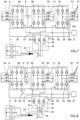
- a vehicle electrical system comprising an electrical storage system, a first multiphase electrical machine having a plurality of stator windings, a first inverter connected to the electrical storage system and to the first multiphase electrical machine, wherein the first inverter has a plurality of switch legs with switches, a second multiphase electrical machine having a plurality of stator windings, a second inverter connected to the electrical storage system and to the second multiphase electrical machine, wherein the second inverter has a plurality of switch legs with switches, a terminal having a plurality of poles and configured for receiving single-phase AC or multi-phase AC or DC from a vehicle external charging source, a first conductive line connecting a first pole of the terminal with a first switch leg of the first inverter, a second conductive line connecting a second pole of the terminal with a first switch leg of the second inverter, a first inductor arranged in one of the first and second conductive line, and a control system
- a method for charging an electrical storage system of a vehicle electrical system comprises the steps of connecting a first inverter to a first multiphase electrical machine having a plurality of stator windings and to the electrical storage system, wherein the first inverter has a plurality of switch legs with switches, connecting a second inverter to a second multiphase electrical machine having a plurality of stator windings and to the electrical storage system, wherein the second inverter has a plurality of switch legs with switches, connecting a first pole of a terminal with a first switch leg of the first inverter via a first conductive line, connecting a second pole of the terminal with a first switch leg of the second inverter via a second conductive line, providing a first inductor in one of the first and second conductive lines, connecting the terminal having a plurality of poles to a vehicle external charging source configured for supplying single-phase AC or multi-phase AC or DC, and controlling operation of the switches of the
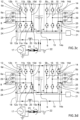
- the control system when the control system is configured for charging the electrical storage system using electrical energy supplied from the vehicle external charging source in a voltage step-down mode, the control system is configured to operate the first supply switch and the step-down switch, such that a charging current during an on-period of the step-down switch flows from a negative pole of the electrical storage system, through the intrinsic or extrinsic reverse diode associated with a first switch of the first switch leg of the second inverter, the second conductive line, the first inductor, the step-down switch, the first conductive line, an intrinsic or extrinsic reverse diode associated with a second switch of the first switch leg of the first inverter, and to a positive pole of the electrical storage system.
- a straight-forward and easily implemented step-down solution is accomplished, that also can be implemented without changing or customizing the design or structure of the inverters and/or electrical machines.
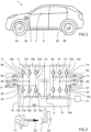
- the first and second multiphase electrical machines 5a, 5b may for example be three-phase, five-phase, or seven-phase electrical machines, or the like.
- a three-phase electrical machine may for example have three stator windings, each divided in two halves that are arranged on opposite sides in the stator. The three stator windings may then be disposed 120 degrees apart from each other, and each stator winding may then be deemed having two magnetic poles, i.e. a three-phase two-pole electrical machine. However, the stator windings may alternatively be distributed into four sections, wherein each section is displaced 90 degrees apart from each other. Such a stator winding is deemed having four poles, i.e. a three-phase four-pole electrical machine. Other stator winding arrangements are possible, such as six-pole arrangement, or the like.
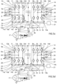
- the other switches of the first and second inverters 9a, 9b shall be controlled to remain in the open state during the step-up mode described above.
- control system 21 when the control system 21 is configured for charging the electrical storage system 6 using electrical energy supplied from the vehicle external charging source 17 in a voltage step-down mode, the control system 21 is configured to operate the first supply switch 30 and the step-down switch 31 synchronised and with alternating on and off periods.
- the control system 21 when the control system 21 is configured for charging the electrical storage system 6 using electrical energy supplied from the vehicle external charging source 17 in a voltage step-down mode, the control system 21 is configured to operate the first supply switch 30 and the step-down switch 31, such that a charging current during an on-period of the step-down switch 31 flows from the negative pole of the electrical storage system 6, through the intrinsic or extrinsic reverse diode 14c associated with a first switch 14a of the first switch leg 14 of the second inverter 9b, the second conductive line 19, the step-down switch 31 in a closed state, the first conductive line 18 including the first inductor 20, an intrinsic or extrinsic reverse diode 10d associated with a second switch 10b of the first switch leg 10 of the first inverter 9a, and to a positive pole of the electrical storage system 6.
- the external voltage source 17 will be disconnected from the charging circuit and the charging current will start to decrease.
- the decreasing current will produce a voltage drop across the first inductor caused by the sinking stored energy in the inductor's magnetic field, such that the first inductor becomes current source driving a continued charging current. With time, the voltage drop of the first inductor become smaller and the charging current sinks.
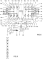
- the example embodiments of the vehicle electrical system described above are configured for being supplied with DC or single phase AC from the vehicle external charging source 17 for charging of the electrical storage system 6. However, in certain applications is may be desirable to charge the electrical storage system with three-phase AC from the vehicle external charging source 17.
- Such an example embodiment is schematically illustrated in figure 7 , wherein the vehicle external charging source 17 is a three-phase power source connected to the external charging connector 23.
- the vehicle electrical system of figure 7 comprises, in addition to the features described with reference to figure 2 , a third multiphase electrical machine 5c having a plurality of stator windings 37, a third inverter 9c connected to the electrical storage system 6 and to the third multiphase electrical machine 5c, wherein the third inverter 9c has a plurality of switch legs with switches, a third conductive line 38 connecting a third pole of the terminal 7 with a first switch leg 39 of the third inverter 9c, a second inductor 35 arranged in the second conductive line 19, a third inductor 40 arranged in the third conductive line 38, wherein the first inductor 20 is arranged in the first conductive line 18, and wherein the control system 21 is operatively coupled to each of the first, second and third inverters 9a, 9b, 9c and configured for controlling operation of the switches of the first, second and third inverters 9a, 9b, 9c for preventing charging current from passing through any of the stator windings 8, 13, 37 of the stator
- the method further comprises a second step S2 of connecting a second inverter 9b to a second multiphase electrical machine 5b having a plurality of stator windings 13 and to the electrical storage system 6, wherein the second inverter 9b has a plurality of switch legs 14, 15, 16 with switches.
- the method additionally includes a third step S3 of connecting a first pole of a terminal 7 with a first switch leg 10 of the first inverter 9a via a first conductive line 18, and a fourth step S4 of connecting a second pole of the terminal 7 with a first switch leg 14 of the second inverter 9b via a second conductive line 19.
Landscapes
- Engineering & Computer Science (AREA)
- Power Engineering (AREA)
- Transportation (AREA)
- Mechanical Engineering (AREA)
- Charge And Discharge Circuits For Batteries Or The Like (AREA)
- Electric Propulsion And Braking For Vehicles (AREA)
Claims (15)
- Elektrisches Fahrzeugsystem, umfassend:ein elektrisches Speichersystem (6),eine erste mehrphasige elektrische Maschine (5a), die eine Vielzahl von Statorwicklungen (8) aufweist,einen ersten Wechselrichter (9a), der mit dem elektrischen Speichersystem (6) und der ersten mehrphasigen elektrischen Maschine (5a) verbunden ist, wobei der erste Wechselrichter (9a) eine Vielzahl von Schalterzweigen (10, 11, 12) mit Schaltern (10a, 10b, 11a, 11b, 12a, 12b) aufweist,eine zweite mehrphasige elektrische Maschine (5b), die eine Vielzahl von Statorwicklungen (13) aufweist,einen zweiten Wechselrichter (9b), der mit dem elektrischen Speichersystem (6) und der zweiten mehrphasigen elektrischen Maschine (5b) verbunden ist, wobei der zweite Wechselrichter (9b) eine Vielzahl von Schalterzweigen (14, 15, 16) mit Schaltern (14a, 14b) aufweist,einen Anschluss (7), der eine Vielzahl von Polen aufweist und dazu konfiguriert ist, einphasigen Wechselstrom oder mehrphasigen Wechselstrom oder Gleichstrom von einer externen Fahrzeugladequelle (17) zu empfangen,eine erste leitfähige Leitung (18), die einen ersten Pol des Anschlusses (7) mit einem ersten Schalterzweig (10) des ersten Wechselrichters (9a) verbindet,eine zweite leitfähige Leitung (19), die einen zweiten Pol des Anschlusses (7) mit einem ersten Schalterzweig (14) des zweiten Wechselrichters (9b) verbindet,dadurch gekennzeichnet, dass es Folgendes umfasst:einen ersten Induktor (20), der in einer der ersten und zweiten leitfähigen Leitung (18, 19) angeordnet ist, undein Steuerungssystem (21), das an den ersten und zweiten Wechselrichter (9a, 9b) wirkgekoppelt ist und dazu konfiguriert ist, einen Betrieb der Schalter des ersten und zweiten Wechselrichters (9a, 9b) zu steuern, um zu verhindern, dass während einer Übertragung von elektrischer Ladung von der externen Fahrzeugladequelle (17) an das elektrische Speichersystem (6) ein Ladestrom durch eine beliebige der Statorwicklungen (8, 13) der ersten und zweiten mehrphasigen elektrischen Maschine (5a, 5b) fließt.
- Elektrisches Fahrzeugsystem nach Anspruch 1, wobei, wenn das Steuerungssystem (21) dazu konfiguriert ist, das elektrische Speichersystem (6) unter Verwendung elektrischer Energie, die von der externen Fahrzeugladequelle (17) in einem Spannungshochtransformationsmodus bereitgestellt wird, zu laden, das Steuerungssystem (21) dazu konfiguriert ist, einen ersten Schalter (10a) des ersten Schalterzweigs (10) des ersten Wechselrichters (9a) mit abwechselnden An- und Aus-Zeiträumen so zu betreiben, dass ein Ladestrom während eines An-Zeitraums von der externen Fahrzeugladequelle (17) durch die erste leitfähige Leitung (18), den ersten Schalter (10a) des ersten Schalterzweigs (10) des ersten Wechselrichters (9a), eine intrinsische oder extrinsische Rückwärtsdiode (14c), die einem ersten Schalter (14a) des ersten Schalterzweigs (14) des zweiten Wechselrichters (9b) zugeordnet ist, die zweite leitfähige Leitung (19), den ersten Induktor (20) und zurück zu der externen Fahrzeugladequelle (17) fließt, während das elektrische Speichersystem (6) umgangen wird, und so dass ein Ladestrom während eines Aus-Zeitraums von einem negativen Pol des elektrischen Speichersystems (6) durch die intrinsische oder extrinsische Rückwärtsdiode (14c), die dem ersten Schalter (14a) des ersten Schalterzweigs (14) des zweiten Wechselrichters (9b) zugeordnet ist, die zweite leitfähige Leitung (19), den ersten Induktor (20), die externe Fahrzeugladequelle (17), die erste leitfähige Leitung (18), eine intrinsische oder extrinsische Rückwärtsdiode (10d), die einem zweiten Schalter (10b) des ersten Schalterzweigs (10) des ersten Wechselrichters (9a) zugeordnet ist, zu einem positiven Pol des elektrischen Speichersystems (6) fließt.
- Elektrisches Fahrzeugsystem nach Anspruch 2, wobei, wenn es sich bei der externen Fahrzeugladequelle (17) um Wechselstrom zum Laden des elektrischen Speichersystems (6) in einem Spannungshochtransformationsmodus handelt, das Steuerungssystem (21) den Betrieb des ersten Schalterzweigs (10) des erstens Wechselrichters (9a) und des ersten Schalterzweigs (14) des zweiten Wechselrichters (9b) selektiv so steuert, dass elektrischer Stromfluss zwischen den Folgenden abwechselt:Fließen durch den ersten Schalter (10a) des ersten Schalterzweigs (10) des erstens Wechselrichters (9a), um das elektrische Speichersystem (6) während eines ersten Versorgungsspannungspolaritätszustands zu laden, undFließen durch den ersten Schalter (14a) des ersten Schalterzweigs (14) des zweiten Wechselrichters (9b), um das elektrische Speichersystem (6) während eines zweiten Versorgungsspannungspolaritätszustands zu laden.
- Elektrisches Fahrzeugsystem nach einem der vorhergehenden Ansprüche, wobei das elektrische Fahrzeugsystem ferner Folgendes umfasst:einen ersten Versorgungsschalter (30), der in einer der ersten und zweiten leitfähigen Leitung (18, 19) angeordnet ist und dazu konfiguriert ist, die erste oder zweite leitfähige Leitung (18, 19) selektiv zu öffnen oder zu schließen, undeinen Abwärtstransformationsschalter (31), der mit der ersten und zweiten leitfähigen Leitung (18, 19) wirkverbunden ist und dazu konfiguriert ist, eine Verbindung zwischen der ersten oder zweiten leitfähigen Leitung (18, 19) selektiv zu öffnen und zu schließen,wobei der erste Versorgungsschalter (30), der Abwärtstransformationsschalter (31) und der erste Induktor (20) so angeordnet sind, dass sie einen Stromfluss zwischen einem Abschnitt der ersten leitfähigen Leitung (18) und einem Abschnitt der zweiten leitfähigen Leitung (19) über den Abwärtstransformationsschalter (31) und den ersten Induktor (20) zulassen, wenn der erste Versorgungsschalter (30) sich in einem offenen Zustand befindet.
- Elektrisches Fahrzeugsystem nach Anspruch 4, wobei, wenn das Steuerungssystem (21) dazu konfiguriert ist, das elektrische Speichersystem (6) unter Verwendung elektrischer Energie, die von der externen Fahrzeugladequelle (17) in einem Spannungsabwärtstransformationsmodus bereitgestellt wird, zu laden, das Steuerungssystem (21) dazu konfiguriert ist, den ersten Versorgungsschalter (30) und den Abwärtstransformationsschalter (31) synchronisiert und mit abwechselnden An- und Aus-Zeiträumen zu betreiben.
- Elektrisches Fahrzeugsystem nach einem der vorhergehenden Ansprüche 4-5, wobei, wenn das Steuerungssystem (21) dazu konfiguriert ist, das elektrische Speichersystem (6) unter Verwendung elektrischer Energie, die von der externen Fahrzeugladequelle (17) in einem Spannungsabwärtstransformationsmodus bereitgestellt wird, zu laden, das Steuerungssystem (21) dazu konfiguriert ist, den ersten Versorgungsschalter (30) in einen geschlossenen Zustand zu versetzen, wenn der Abwärtstransformationsschalter (31) in einen offenen Zustand versetzt ist, und umgekehrt.
- Elektrisches Fahrzeugsystem nach einem der vorhergehenden Ansprüche 4-6, wobei, wenn das Steuerungssystem (21) dazu konfiguriert ist, das elektrische Speichersystem (6) unter Verwendung elektrischer Energie, die von der externen Fahrzeugladequelle (17) in einem Spannungsabwärtstransformationsmodus bereitgestellt wird, zu laden, das Steuerungssystem (21) dazu konfiguriert ist, alle Schalter des ersten und zweiten Wechselrichters (9a, 9b) in einem offenen Zustand zu belassen.
- Elektrisches Fahrzeugsystem nach einem der vorhergehenden Ansprüche 4-7, wobei, wenn das Steuerungssystem (21) dazu konfiguriert ist, das elektrische Speichersystem (6) unter Verwendung elektrischer Energie, die von der externen Fahrzeugladequelle (17) in einem Spannungsabwärtstransformationsmodus bereitgestellt wird, zu laden, das Steuerungssystem (21) dazu konfiguriert ist, den ersten Versorgungsschalter (30) und den Abwärtstransformationsschalter (31) so zu betreiben, dass ein Ladestrom während eines An-Zeitraums des ersten Versorgungsschalters (30) von einem negativen Pol des elektrischen Speichersystems (6) durch die intrinsische oder extrinsische Rückwärtsdiode (14c), die einem ersten Schalter (14a) des ersten Schalterzweigs (14) des zweiten Wechselrichters (9b) zugeordnet ist, die zweite leitfähige Leitung (19), den ersten Induktor (20), die externe Fahrzeugladequelle (17), die erste leitfähige Leitung (18), eine intrinsische oder extrinsische Rückwärtsdiode (10d), die einem zweiten Schalter (10b) des ersten Schalterzweigs (10) des ersten Wechselrichters (9a) zugeordnet ist, und zu einem positiven Pol des elektrischen Speichersystems (6) fließt.
- Elektrisches Fahrzeugsystem nach einem der vorhergehenden Ansprüche 4-8, wobei, wenn das Steuerungssystem (21) dazu konfiguriert ist, das elektrische Speichersystem (6) unter Verwendung elektrischer Energie, die von der externen Fahrzeugladequelle (17) in einem Spannungsabwärtstransformationsmodus bereitgestellt wird, zu laden, das Steuerungssystem (21) dazu konfiguriert ist, den ersten Versorgungsschalter (30) und den Abwärtstransformationsschalter (31) so zu betreiben, dass ein Ladestrom während eines An-Zeitraums des Abwärtstransformationsschalters (31) von einem negativen Pol des elektrischen Speichersystems (6) durch die intrinsische oder extrinsische Rückwärtsdiode (14c), die einem ersten Schalter (14a) des ersten Schalterzweigs (14) des zweiten Wechselrichters (9b) zugeordnet ist, die zweite leitfähige Leitung (19), den ersten Induktor (20), den Abwärtstransformationsschalter (31), die erste leitfähige Leitung (18), eine intrinsische oder extrinsische Rückwärtsdiode (10d), die einem zweiten Schalter (10b) des ersten Schalterzweigs (10) des ersten Wechselrichters (9a) zugeordnet ist, und zu einem positiven Pol des elektrischen Speichersystems (6) fließt.
- Elektrisches Fahrzeugsystem nach einem der vorhergehenden Ansprüche 4-9, wobei, wenn das Steuerungssystem (21) dazu konfiguriert ist, das elektrische Speichersystem (6) unter Verwendung elektrischer Wechselstromenergie, die von der externen Fahrzeugladequelle (17) in einem Spannungsabwärtstransformationsmodus bereitgestellt wird, zu laden, das Steuerungssystem (21) dazu konfiguriert ist, den ersten Versorgungsschalter (30) und den Abwärtstransformationsschalter (31) so zu betreiben, dass ein Ladestrom zwischen den Folgenden abwechselt:Fließen durch die intrinsische oder extrinsische Rückwärtsdiode (10d), die einem zweiten Schalter (10b) des ersten Schalterzweigs (10) des ersten Wechselrichters (9a) zugeordnet ist, und eine intrinsische oder extrinsische Rückwärtsdiode (14c), die einem ersten Schalter (14a) des ersten Schalterzweigs (14) des zweiten Wechselrichters (9b) zugeordnet ist, um das elektrische Speichersystem (6) während eines ersten Versorgungsspannungspolaritätszustands zu laden, undFließen durch die intrinsische oder extrinsische Rückwärtsdiode (14d), die einem zweiten Schalter (14b) des ersten Schalterzweigs (14) des zweiten Wechselrichters (9b) zugeordnet ist, und eine intrinsische oder extrinsische Rückwärtsdiode (10c), die einem ersten Schalter (10a) des ersten Schalterzweigs (10) des ersten Wechselrichters (9a) zugeordnet ist, um das elektrische Speichersystem (6) während eines zweiten Versorgungsspannungspolaritätszustands zu laden.
- Elektrisches Fahrzeugsystem nach einem der vorhergehenden Ansprüche, wobei das elektrische Fahrzeugsystem ferner Folgendes umfasst:eine dritte mehrphasige elektrische Maschine (5c), die eine Vielzahl von Statorwicklungen (37) aufweist,einen dritten Wechselrichter (9c), der mit dem elektrischen Speichersystem (6) und der dritten mehrphasigen elektrischen Maschine (5c) verbunden ist, wobei der dritte Wechselrichter (9c) eine Vielzahl von Schalterzweigen (39) mit Schaltern (39a) aufweist,eine dritte leitfähige Leitung (38), die einen dritten Pol des Anschlusses (7) mit einem ersten Schalterzweig (39) des dritten Wechselrichters (9c) verbindet,einen zweiten Induktor (35), der in der zweiten leitfähigen Leitung (19) angeordnet ist,einen dritten Induktor (40), der in der dritten leitfähigen Leitung (38) angeordnet ist,wobei der erste Induktor (20) in der ersten leitfähigen Leitung (18) angeordnet ist undwobei das Steuerungssystem (21) mit jedem des ersten, zweiten und dritten Wechselrichters (9a, 9b, 9c) wirkgekoppelt ist und dazu konfiguriert ist, den Betrieb der Schalter des ersten, zweiten und dritten Wechselrichters (9a, 9b, 9c) zu steuern, um zu verhindern, dass während dreiphasigen Ladens des elektrischen Speichersystems (6) von der externen Fahrzeugladequelle (17) ein Ladestrom durch eine beliebige der Statorwicklungen (8, 13, 37) der ersten, zweiten und dritten mehrphasigen elektrischen Maschine (5a, 5b, 5c) fließt.
- Verfahren zum Laden eines elektrischen Speichersystems (6) eines elektrischen Fahrzeugsystems, wobei das Verfahren Folgendes umfasst:Verbinden eines ersten Wechselrichters (9a) mit einer ersten mehrphasigen elektrischen Maschine (5a), die eine Vielzahl von Statorwicklungen (8) aufweist, und dem elektrischen Speichersystem (6), wobei der erste Wechselrichter (9a) eine Vielzahl von Schalterzweigen (10, 11, 12) mit Schaltern (10a, 10b, 11a, 11b, 12a, 12b) aufweist,Verbinden eines zweiten Wechselrichters (9b) mit einer zweiten mehrphasigen elektrischen Maschine (5b), die eine Vielzahl von Statorwicklungen (13) aufweist, und dem elektrischen Speichersystem (6), wobei der zweite Wechselrichter (9b) eine Vielzahl von Schalterzweigen (14, 15, 16) mit Schaltern (14a, 14b) aufweist,Verbinden eines ersten Pols eines Anschlusses (7) mit einem ersten Schalterzweig (10) des ersten Wechselrichters (9a) über eine erste leitfähige Leitung (18),Verbinden eines zweiten Pols des Anschlusses (7) mit einem ersten Schalterzweig (14) des zweiten Wechselrichters (9b) über eine zweite leitfähige Leitung (19), gekennzeichnet durchBereitstellen eines ersten Induktors (20) in einer der ersten und zweiten leitfähigen Leitung (18, 19),Verbinden des Anschlusses (7), der eine Vielzahl von Polen aufweist, mit einer externen Fahrzeugladequelle (17), die dazu konfiguriert ist, einphasigen Wechselstrom oder mehrphasigen Wechselstrom oder Gleichstrom bereitzustellen, undSteuern des Betriebs der Schalter des ersten und zweiten Wechselrichters (9a, 9b), um zu verhindern, dass während einer Übertragung einer elektrischen Ladung von der externen Fahrzeugladequelle (17) an das elektrische Speichersystem (6) ein Ladestrom durch eine beliebige der Statorwicklungen (8, 13) der ersten und zweiten mehrphasigen elektrischen Maschine (5a, 5b) fließt.
- Verfahren nach Anspruch 12, wobei, beim Laden des elektrischen Speichersystems (6) unter Verwendung elektrischer Energie, die von der externen Fahrzeugladequelle (17) in einem Spannungshochtransformationsmodus bereitgestellt wird, Betreiben eines ersten Schalters (10a) des ersten Schalterzweigs (10) des ersten Wechselrichters (9a) mit abwechselnden An- und Aus-Zeiträumen, so dass ein Ladestrom während eines An-Zeitraums von der externen Fahrzeugladequelle (17) durch die erste leitfähige Leitung (18), den ersten Schalter (10a) des ersten Schalterzweigs (10) des ersten Wechselrichters (9a), eine intrinsische oder extrinsische Rückwärtsdiode (14c), die einem ersten Schalter des ersten Schalterzweigs des zweiten Wechselrichters (9b) zugeordnet ist, die zweite leitfähige Leitung (19), den ersten Induktor (20) und zurück zu der externen Fahrzeugladequelle (17) fließt, während das elektrische Speichersystem (6) umgangen wird, und so dass ein Ladestrom während eines Aus-Zeitraums von einem negativen Pol des elektrischen Speichersystems (6) durch die intrinsische oder extrinsische Rückwärtsdiode (14c), die dem ersten Schalter (14a) des ersten Schalterzweigs (14) des zweiten Wechselrichters (9b) zugeordnet ist, die zweite leitfähige Leitung (19), den ersten Induktor (20), die externe Fahrzeugladequelle (17), die erste leitfähige Leitung (18), eine intrinsische oder extrinsische Rückwärtsdiode (10d), die einem zweiten Schalter (10b) des ersten Schalterzweigs (10) des ersten Wechselrichters (9a) zugeordnet ist, zu einem positiven Pol des elektrischen Speichersystems (6) fließt.
- Verfahren nach einem der vorhergehenden Ansprüche 12-13, ferner umfassend:Bereitstellen eines ersten Versorgungsschalters (30) in einer der ersten und zweiten leitfähigen Leitung (18, 19), der dazu konfiguriert ist, die erste oder zweite leitfähige Leitung (18, 19) selektiv zu öffnen oder zu schließen, undBereitstellen eines Abwärtstransformationsschalters (31), der mit der ersten und zweiten leitfähigen Leitung (18, 19) wirkverbunden ist und dazu konfiguriert ist, eine Verbindung zwischen der ersten oder zweiten leitfähigen Leitung (18, 19) selektiv zu öffnen und zu schließen,wobei der erste Versorgungsschalter (30), der Abwärtstransformationsschalter (31) und der erste Induktor (20) so angeordnet sind, dass sie einen Stromfluss zwischen einem Abschnitt der ersten leitfähigen Leitung (18) und einem Abschnitt der zweiten leitfähigen Leitung (19) über den Abwärtstransformationsschalter (31) und den ersten Induktor (20) zulassen, wenn der erste Versorgungsschalter (30) sich in einem offenen Zustand befindet.
- Verfahren nach Anspruch 14, ferner umfassend Laden des elektrischen Speichersystems (6) unter Verwendung elektrischer Energie, die von der externen Fahrzeugladequelle (17) in einem Spannungsabwärtstransformationsmodus bereitgestellt wird, durch Betreiben des ersten Versorgungsschalters (30) und des Abwärtstransformationsschalter (31), so dass:ein Ladestrom während eines An-Zeitraums des ersten Versorgungsschalters (30) von einem negativen Pol des elektrischen Speichersystems (6) durch die intrinsische oder extrinsische Rückwärtsdiode (14c), die einem ersten Schalter (14a) des ersten Schalterzweigs (14) des zweiten Wechselrichters (9b) zugeordnet ist, die zweite leitfähige Leitung (19), den ersten Induktor (20), die externe Fahrzeugladequelle (17), die erste leitfähige Leitung (18), eine intrinsische oder extrinsische Rückwärtsdiode (10d), die einem zweiten Schalter (10b) des ersten Schalterzweigs (10) des ersten Wechselrichters (9a) zugeordnet ist, und zu einem positiven Pol des elektrischen Speichersystems (6) fließt undein Ladestrom während eines An-Zeitraums des Abwärtstransformationsschalters (31) von einem negativen Pol des elektrischen Speichersystems (6) durch die intrinsische oder extrinsische Rückwärtsdiode (14c), die einem ersten Schalter (14) des ersten Schalterzweigs (14) des zweiten Wechselrichters (9b) zugeordnet ist, die zweite leitfähige Leitung (19), den ersten Induktor (20), den Abwärtstransformationsschalter (31), die erste leitfähige Leitung (18), eine intrinsische oder extrinsische Rückwärtsdiode (10d), die einem zweiten Schalter (10b) des ersten Schalterzweigs (10) des ersten Wechselrichters (9a) zugeordnet ist, und zu einem positiven Pol des elektrischen Speichersystems (6) fließt.
Priority Applications (4)
| Application Number | Priority Date | Filing Date | Title |
|---|---|---|---|
| EP20157083.5A EP3866295B1 (de) | 2020-02-13 | 2020-02-13 | Elektrisches fahrzeugsystem |
| PCT/CN2021/075305 WO2021160022A1 (en) | 2020-02-13 | 2021-02-04 | Vehicle electrical system |
| CN202180011961.0A CN115023895B (zh) | 2020-02-13 | 2021-02-04 | 交通工具电气系统 |
| US17/853,448 US12576733B2 (en) | 2020-02-13 | 2022-06-29 | Vehicle electrical system |
Applications Claiming Priority (1)
| Application Number | Priority Date | Filing Date | Title |
|---|---|---|---|
| EP20157083.5A EP3866295B1 (de) | 2020-02-13 | 2020-02-13 | Elektrisches fahrzeugsystem |
Publications (2)
| Publication Number | Publication Date |
|---|---|
| EP3866295A1 EP3866295A1 (de) | 2021-08-18 |
| EP3866295B1 true EP3866295B1 (de) | 2024-07-10 |
Family
ID=69582000
Family Applications (1)
| Application Number | Title | Priority Date | Filing Date |
|---|---|---|---|
| EP20157083.5A Active EP3866295B1 (de) | 2020-02-13 | 2020-02-13 | Elektrisches fahrzeugsystem |
Country Status (4)
| Country | Link |
|---|---|
| US (1) | US12576733B2 (de) |
| EP (1) | EP3866295B1 (de) |
| CN (1) | CN115023895B (de) |
| WO (1) | WO2021160022A1 (de) |
Families Citing this family (8)
| Publication number | Priority date | Publication date | Assignee | Title |
|---|---|---|---|---|
| DE102021003882A1 (de) | 2021-07-27 | 2021-09-09 | Daimler Ag | Elektrisches Antriebssystem für ein Fahrzeug, sowie Verfahren zum Betreiben eines elektrischen Antriebssystems |
| DE102021208773B3 (de) | 2021-08-11 | 2022-08-18 | Volkswagen Aktiengesellschaft | Traktionsnetz für ein Elektrofahrzeug und Verfahren zum Laden |
| CN113879154B (zh) * | 2021-09-27 | 2023-05-23 | 重庆长安新能源汽车科技有限公司 | 一种匹配多种电压平台的电动汽车充电电驱系统 |
| DE102021133266A1 (de) * | 2021-12-15 | 2023-06-15 | Schaeffler Technologies AG & Co. KG | Anordnung zur Strom- bzw. Spannungsversorgung eines elektrischen Antriebes |
| CN117674373A (zh) * | 2022-08-31 | 2024-03-08 | 比亚迪股份有限公司 | 充电和驱动一体化系统、整车系统及控制方法 |
| CN115817231B (zh) * | 2022-12-15 | 2024-04-30 | 小米汽车科技有限公司 | 电动汽车及其充电装置 |
| JP7893241B2 (ja) * | 2023-12-27 | 2026-07-22 | トヨタ自動車株式会社 | 充電システム |
| JP2025109509A (ja) * | 2024-01-12 | 2025-07-25 | トヨタ自動車株式会社 | 充電システム |
Family Cites Families (20)
| Publication number | Priority date | Publication date | Assignee | Title |
|---|---|---|---|---|
| US6683389B2 (en) * | 2000-06-30 | 2004-01-27 | Capstone Turbine Corporation | Hybrid electric vehicle DC power generation system |
| JP4285458B2 (ja) * | 2005-08-08 | 2009-06-24 | トヨタ自動車株式会社 | 車両の電源装置およびその制御方法 |
| JP4367391B2 (ja) * | 2005-09-01 | 2009-11-18 | トヨタ自動車株式会社 | 充電制御装置および電動車両 |
| JP2007068358A (ja) * | 2005-09-01 | 2007-03-15 | Toyota Motor Corp | 電動車両 |
| US7733039B2 (en) * | 2006-10-19 | 2010-06-08 | Ut-Battelle, Llc | Electric vehicle system for charging and supplying electrical power |
| US7579792B2 (en) * | 2007-04-23 | 2009-08-25 | Gm Global Technology Operations, Inc. | Hybrid motor boost system and methods |
| JP4609474B2 (ja) * | 2007-10-10 | 2011-01-12 | 株式会社デンソー | 回転電機装置 |
| US20100268406A1 (en) | 2008-01-11 | 2010-10-21 | Toyota Jidosha Kabushiki Kaisha | Charging control apparatus for vehicle and vehicle |
| JP4561878B2 (ja) | 2008-06-05 | 2010-10-13 | トヨタ自動車株式会社 | 蓄電装置を搭載する車両および充電ケーブル |
| US8183820B2 (en) | 2008-07-21 | 2012-05-22 | GM Global Technology Operations LLC | Power processing systems and methods for use in plug-in electric vehicles |
| FR2944653B1 (fr) | 2009-04-15 | 2016-03-11 | Renault Sas | Vehicule automobile a propulsion electrique et borne de charge de la batterie d'un tel vehicule |
| GB2477128B (en) * | 2010-01-22 | 2012-05-30 | Protean Electric Ltd | A switching device |
| DE102010062376A1 (de) | 2010-12-03 | 2012-06-06 | Zf Friedrichshafen Ag | Verfahren zum Laden einer Traktionsbatterie |
| DE102012220376A1 (de) | 2012-11-08 | 2014-05-08 | Robert Bosch Gmbh | Vorrichtung und Verfahren zum Laden eines elektrischen Energiespeichers aus einer Wechselspannungsquelle |
| CN103434415A (zh) * | 2013-08-09 | 2013-12-11 | 浙江吉利汽车研究院有限公司 | 机动车驱动系统 |
| US9783070B2 (en) * | 2014-02-14 | 2017-10-10 | Jabil Circuit, Inc. | Charge transfer system |
| GB2531039A (en) * | 2014-10-08 | 2016-04-13 | Nissan Motor Mfg (Uk) Ltd | Electric drive and charger system for a grid enabled vehicle |
| DE102015207413B4 (de) | 2015-04-23 | 2025-12-04 | Schaeffler Technologies AG & Co. KG | Leistungsschaltung zur Stromversorgung in einem elektrisch angetriebenen Fahrzeug |
| JP7048059B2 (ja) | 2017-10-13 | 2022-04-05 | ザ ガバニング カウンシル オブ ザ ユニバーシティ オブ トロント | 電動車両用オンボード双方向ac急速充電器 |
| DE102018009848A1 (de) | 2018-12-14 | 2019-06-27 | Daimler Ag | Schaltungsanordnung für ein Kraftfahrzeug, insbesondere für ein Hybrid- oder Elektrofahrzeug |
-
2020
- 2020-02-13 EP EP20157083.5A patent/EP3866295B1/de active Active
-
2021
- 2021-02-04 WO PCT/CN2021/075305 patent/WO2021160022A1/en not_active Ceased
- 2021-02-04 CN CN202180011961.0A patent/CN115023895B/zh active Active
-
2022
- 2022-06-29 US US17/853,448 patent/US12576733B2/en active Active
Also Published As
| Publication number | Publication date |
|---|---|
| EP3866295A1 (de) | 2021-08-18 |
| CN115023895A (zh) | 2022-09-06 |
| US20220324340A1 (en) | 2022-10-13 |
| CN115023895B (zh) | 2025-04-25 |
| WO2021160022A1 (en) | 2021-08-19 |
| US12576733B2 (en) | 2026-03-17 |
Similar Documents
| Publication | Publication Date | Title |
|---|---|---|
| US12576733B2 (en) | Vehicle electrical system | |
| EP3988377B1 (de) | Elektrisches fahrzeugsystem | |
| US9350287B2 (en) | Vehicle with electrical machine and method for operating the same | |
| CN108382215B (zh) | 多逆变器的混合动力驱动系统 | |
| US10439541B2 (en) | Vehicle with electrical machine and method for operating the same | |
| US7816805B2 (en) | Power supply system with multiphase motor and multiphase inverter | |
| CN108482142B (zh) | 用于降低具有多个三相电驱动装置的电气化车辆动力传动系统中的噪声的系统和方法 | |
| US8994318B2 (en) | Electrical on-board network and method for operating an electrical on-board network | |
| CN103872970B (zh) | 用于操作电机的电路装置和方法 | |
| EP2928061B1 (de) | Stromwandlersystem und verfahren zur steuerung davon | |
| EP3121952B1 (de) | Geschalteter reluktanzmotor mit treiberschaltung und verfahren zur steuerung eines geschalteten reluktanzmotors | |
| JP2025008106A (ja) | 車載充電装置 | |
| CN110626183A (zh) | 隔离双总线混合动力车辆动力传动系统 | |
| US20200162005A1 (en) | Partial-load phase deactivation of polyphase electric machine | |
| JP2025008108A (ja) | 車載充電装置 | |
| JPH09298840A (ja) | 電気自動車の充電装置 | |
| CN119428261A (zh) | 车载充电装置 | |
| JP2015216824A (ja) | トラクションモータ駆動装置 | |
| CN110620462A (zh) | 共模电流减小混合动力驱动系统 | |
| JP2004015895A (ja) | 電気負荷駆動装置 | |
| JP4153760B2 (ja) | モータ回路およびモータ制御方法 | |
| CN119773543A (zh) | 电动车辆推进和充电系统 | |
| US20250233443A1 (en) | Charging system | |
| JP7589624B2 (ja) | 電源システム | |
| Liu et al. | The control strategy for integrated motor-drive and battery-charging system based on the split-field-winding doubly salient electromagnetic machine in charging mode |
Legal Events
| Date | Code | Title | Description |
|---|---|---|---|
| PUAI | Public reference made under article 153(3) epc to a published international application that has entered the european phase |
Free format text: ORIGINAL CODE: 0009012 |
|
| STAA | Information on the status of an ep patent application or granted ep patent |
Free format text: STATUS: REQUEST FOR EXAMINATION WAS MADE |
|
| 17P | Request for examination filed |
Effective date: 20200213 |
|
| AK | Designated contracting states |
Kind code of ref document: A1 Designated state(s): AL AT BE BG CH CY CZ DE DK EE ES FI FR GB GR HR HU IE IS IT LI LT LU LV MC MK MT NL NO PL PT RO RS SE SI SK SM TR |
|
| GRAP | Despatch of communication of intention to grant a patent |
Free format text: ORIGINAL CODE: EPIDOSNIGR1 |
|
| STAA | Information on the status of an ep patent application or granted ep patent |
Free format text: STATUS: GRANT OF PATENT IS INTENDED |
|
| RIC1 | Information provided on ipc code assigned before grant |
Ipc: B60L 53/22 20190101ALI20240122BHEP Ipc: B60L 53/14 20190101ALI20240122BHEP Ipc: H02J 7/02 20160101ALI20240122BHEP Ipc: B60L 53/24 20190101ALI20240122BHEP Ipc: H02J 7/00 20060101AFI20240122BHEP |
|
| INTG | Intention to grant announced |
Effective date: 20240208 |
|
| GRAS | Grant fee paid |
Free format text: ORIGINAL CODE: EPIDOSNIGR3 |
|
| GRAA | (expected) grant |
Free format text: ORIGINAL CODE: 0009210 |
|
| STAA | Information on the status of an ep patent application or granted ep patent |
Free format text: STATUS: THE PATENT HAS BEEN GRANTED |
|
| AK | Designated contracting states |
Kind code of ref document: B1 Designated state(s): AL AT BE BG CH CY CZ DE DK EE ES FI FR GB GR HR HU IE IS IT LI LT LU LV MC MK MT NL NO PL PT RO RS SE SI SK SM TR |
|
| REG | Reference to a national code |
Ref country code: CH Ref legal event code: EP |
|
| REG | Reference to a national code |
Ref country code: DE Ref legal event code: R096 Ref document number: 602020033598 Country of ref document: DE |
|
| REG | Reference to a national code |
Ref country code: LT Ref legal event code: MG9D |
|
| REG | Reference to a national code |
Ref country code: NL Ref legal event code: MP Effective date: 20240710 |
|
| PG25 | Lapsed in a contracting state [announced via postgrant information from national office to epo] |
Ref country code: PT Free format text: LAPSE BECAUSE OF FAILURE TO SUBMIT A TRANSLATION OF THE DESCRIPTION OR TO PAY THE FEE WITHIN THE PRESCRIBED TIME-LIMIT Effective date: 20241111 |
|
| REG | Reference to a national code |
Ref country code: AT Ref legal event code: MK05 Ref document number: 1702900 Country of ref document: AT Kind code of ref document: T Effective date: 20240710 |
|
| PG25 | Lapsed in a contracting state [announced via postgrant information from national office to epo] |
Ref country code: NL Free format text: LAPSE BECAUSE OF FAILURE TO SUBMIT A TRANSLATION OF THE DESCRIPTION OR TO PAY THE FEE WITHIN THE PRESCRIBED TIME-LIMIT Effective date: 20240710 |
|
| PG25 | Lapsed in a contracting state [announced via postgrant information from national office to epo] |
Ref country code: PT Free format text: LAPSE BECAUSE OF FAILURE TO SUBMIT A TRANSLATION OF THE DESCRIPTION OR TO PAY THE FEE WITHIN THE PRESCRIBED TIME-LIMIT Effective date: 20241111 Ref country code: NL Free format text: LAPSE BECAUSE OF FAILURE TO SUBMIT A TRANSLATION OF THE DESCRIPTION OR TO PAY THE FEE WITHIN THE PRESCRIBED TIME-LIMIT Effective date: 20240710 |
|
| PG25 | Lapsed in a contracting state [announced via postgrant information from national office to epo] |
Ref country code: NO Free format text: LAPSE BECAUSE OF FAILURE TO SUBMIT A TRANSLATION OF THE DESCRIPTION OR TO PAY THE FEE WITHIN THE PRESCRIBED TIME-LIMIT Effective date: 20241010 |
|
| PG25 | Lapsed in a contracting state [announced via postgrant information from national office to epo] |
Ref country code: FI Free format text: LAPSE BECAUSE OF FAILURE TO SUBMIT A TRANSLATION OF THE DESCRIPTION OR TO PAY THE FEE WITHIN THE PRESCRIBED TIME-LIMIT Effective date: 20240710 Ref country code: PL Free format text: LAPSE BECAUSE OF FAILURE TO SUBMIT A TRANSLATION OF THE DESCRIPTION OR TO PAY THE FEE WITHIN THE PRESCRIBED TIME-LIMIT Effective date: 20240710 |
|
| PG25 | Lapsed in a contracting state [announced via postgrant information from national office to epo] |
Ref country code: BG Free format text: LAPSE BECAUSE OF FAILURE TO SUBMIT A TRANSLATION OF THE DESCRIPTION OR TO PAY THE FEE WITHIN THE PRESCRIBED TIME-LIMIT Effective date: 20240710 |
|
| PG25 | Lapsed in a contracting state [announced via postgrant information from national office to epo] |
Ref country code: LV Free format text: LAPSE BECAUSE OF FAILURE TO SUBMIT A TRANSLATION OF THE DESCRIPTION OR TO PAY THE FEE WITHIN THE PRESCRIBED TIME-LIMIT Effective date: 20240710 |
|
| PG25 | Lapsed in a contracting state [announced via postgrant information from national office to epo] |
Ref country code: AT Free format text: LAPSE BECAUSE OF FAILURE TO SUBMIT A TRANSLATION OF THE DESCRIPTION OR TO PAY THE FEE WITHIN THE PRESCRIBED TIME-LIMIT Effective date: 20240710 Ref country code: IS Free format text: LAPSE BECAUSE OF FAILURE TO SUBMIT A TRANSLATION OF THE DESCRIPTION OR TO PAY THE FEE WITHIN THE PRESCRIBED TIME-LIMIT Effective date: 20241110 |
|
| PG25 | Lapsed in a contracting state [announced via postgrant information from national office to epo] |
Ref country code: HR Free format text: LAPSE BECAUSE OF FAILURE TO SUBMIT A TRANSLATION OF THE DESCRIPTION OR TO PAY THE FEE WITHIN THE PRESCRIBED TIME-LIMIT Effective date: 20240710 |
|
| PG25 | Lapsed in a contracting state [announced via postgrant information from national office to epo] |
Ref country code: RS Free format text: LAPSE BECAUSE OF FAILURE TO SUBMIT A TRANSLATION OF THE DESCRIPTION OR TO PAY THE FEE WITHIN THE PRESCRIBED TIME-LIMIT Effective date: 20241010 Ref country code: ES Free format text: LAPSE BECAUSE OF FAILURE TO SUBMIT A TRANSLATION OF THE DESCRIPTION OR TO PAY THE FEE WITHIN THE PRESCRIBED TIME-LIMIT Effective date: 20240710 |
|
| PG25 | Lapsed in a contracting state [announced via postgrant information from national office to epo] |
Ref country code: RS Free format text: LAPSE BECAUSE OF FAILURE TO SUBMIT A TRANSLATION OF THE DESCRIPTION OR TO PAY THE FEE WITHIN THE PRESCRIBED TIME-LIMIT Effective date: 20241010 Ref country code: PL Free format text: LAPSE BECAUSE OF FAILURE TO SUBMIT A TRANSLATION OF THE DESCRIPTION OR TO PAY THE FEE WITHIN THE PRESCRIBED TIME-LIMIT Effective date: 20240710 Ref country code: NO Free format text: LAPSE BECAUSE OF FAILURE TO SUBMIT A TRANSLATION OF THE DESCRIPTION OR TO PAY THE FEE WITHIN THE PRESCRIBED TIME-LIMIT Effective date: 20241010 Ref country code: LV Free format text: LAPSE BECAUSE OF FAILURE TO SUBMIT A TRANSLATION OF THE DESCRIPTION OR TO PAY THE FEE WITHIN THE PRESCRIBED TIME-LIMIT Effective date: 20240710 Ref country code: IS Free format text: LAPSE BECAUSE OF FAILURE TO SUBMIT A TRANSLATION OF THE DESCRIPTION OR TO PAY THE FEE WITHIN THE PRESCRIBED TIME-LIMIT Effective date: 20241110 Ref country code: HR Free format text: LAPSE BECAUSE OF FAILURE TO SUBMIT A TRANSLATION OF THE DESCRIPTION OR TO PAY THE FEE WITHIN THE PRESCRIBED TIME-LIMIT Effective date: 20240710 Ref country code: FI Free format text: LAPSE BECAUSE OF FAILURE TO SUBMIT A TRANSLATION OF THE DESCRIPTION OR TO PAY THE FEE WITHIN THE PRESCRIBED TIME-LIMIT Effective date: 20240710 Ref country code: ES Free format text: LAPSE BECAUSE OF FAILURE TO SUBMIT A TRANSLATION OF THE DESCRIPTION OR TO PAY THE FEE WITHIN THE PRESCRIBED TIME-LIMIT Effective date: 20240710 Ref country code: BG Free format text: LAPSE BECAUSE OF FAILURE TO SUBMIT A TRANSLATION OF THE DESCRIPTION OR TO PAY THE FEE WITHIN THE PRESCRIBED TIME-LIMIT Effective date: 20240710 Ref country code: AT Free format text: LAPSE BECAUSE OF FAILURE TO SUBMIT A TRANSLATION OF THE DESCRIPTION OR TO PAY THE FEE WITHIN THE PRESCRIBED TIME-LIMIT Effective date: 20240710 |
|
| REG | Reference to a national code |
Ref country code: DE Ref legal event code: R097 Ref document number: 602020033598 Country of ref document: DE |
|
| PG25 | Lapsed in a contracting state [announced via postgrant information from national office to epo] |
Ref country code: RO Free format text: LAPSE BECAUSE OF FAILURE TO SUBMIT A TRANSLATION OF THE DESCRIPTION OR TO PAY THE FEE WITHIN THE PRESCRIBED TIME-LIMIT Effective date: 20240710 Ref country code: DK Free format text: LAPSE BECAUSE OF FAILURE TO SUBMIT A TRANSLATION OF THE DESCRIPTION OR TO PAY THE FEE WITHIN THE PRESCRIBED TIME-LIMIT Effective date: 20240710 Ref country code: SM Free format text: LAPSE BECAUSE OF FAILURE TO SUBMIT A TRANSLATION OF THE DESCRIPTION OR TO PAY THE FEE WITHIN THE PRESCRIBED TIME-LIMIT Effective date: 20240710 |
|
| PG25 | Lapsed in a contracting state [announced via postgrant information from national office to epo] |
Ref country code: EE Free format text: LAPSE BECAUSE OF FAILURE TO SUBMIT A TRANSLATION OF THE DESCRIPTION OR TO PAY THE FEE WITHIN THE PRESCRIBED TIME-LIMIT Effective date: 20240710 |
|
| PG25 | Lapsed in a contracting state [announced via postgrant information from national office to epo] |
Ref country code: CZ Free format text: LAPSE BECAUSE OF FAILURE TO SUBMIT A TRANSLATION OF THE DESCRIPTION OR TO PAY THE FEE WITHIN THE PRESCRIBED TIME-LIMIT Effective date: 20240710 |
|
| PG25 | Lapsed in a contracting state [announced via postgrant information from national office to epo] |
Ref country code: SK Free format text: LAPSE BECAUSE OF FAILURE TO SUBMIT A TRANSLATION OF THE DESCRIPTION OR TO PAY THE FEE WITHIN THE PRESCRIBED TIME-LIMIT Effective date: 20240710 Ref country code: IT Free format text: LAPSE BECAUSE OF FAILURE TO SUBMIT A TRANSLATION OF THE DESCRIPTION OR TO PAY THE FEE WITHIN THE PRESCRIBED TIME-LIMIT Effective date: 20240710 |
|
| PLBE | No opposition filed within time limit |
Free format text: ORIGINAL CODE: 0009261 |
|
| STAA | Information on the status of an ep patent application or granted ep patent |
Free format text: STATUS: NO OPPOSITION FILED WITHIN TIME LIMIT |
|
| 26N | No opposition filed |
Effective date: 20250411 |
|
| PG25 | Lapsed in a contracting state [announced via postgrant information from national office to epo] |
Ref country code: SE Free format text: LAPSE BECAUSE OF FAILURE TO SUBMIT A TRANSLATION OF THE DESCRIPTION OR TO PAY THE FEE WITHIN THE PRESCRIBED TIME-LIMIT Effective date: 20240710 |
|
| PG25 | Lapsed in a contracting state [announced via postgrant information from national office to epo] |
Ref country code: MC Free format text: LAPSE BECAUSE OF FAILURE TO SUBMIT A TRANSLATION OF THE DESCRIPTION OR TO PAY THE FEE WITHIN THE PRESCRIBED TIME-LIMIT Effective date: 20240710 |
|
| REG | Reference to a national code |
Ref country code: CH Ref legal event code: PL |
|
| PG25 | Lapsed in a contracting state [announced via postgrant information from national office to epo] |
Ref country code: LU Free format text: LAPSE BECAUSE OF NON-PAYMENT OF DUE FEES Effective date: 20250213 |
|
| PG25 | Lapsed in a contracting state [announced via postgrant information from national office to epo] |
Ref country code: CH Free format text: LAPSE BECAUSE OF NON-PAYMENT OF DUE FEES Effective date: 20250228 |
|
| REG | Reference to a national code |
Ref country code: BE Ref legal event code: MM Effective date: 20250228 |
|
| PGFP | Annual fee paid to national office [announced via postgrant information from national office to epo] |
Ref country code: GB Payment date: 20251201 Year of fee payment: 7 |
|
| PGFP | Annual fee paid to national office [announced via postgrant information from national office to epo] |
Ref country code: FR Payment date: 20251201 Year of fee payment: 7 |
|
| PG25 | Lapsed in a contracting state [announced via postgrant information from national office to epo] |
Ref country code: BE Free format text: LAPSE BECAUSE OF NON-PAYMENT OF DUE FEES Effective date: 20250228 |
|
| PG25 | Lapsed in a contracting state [announced via postgrant information from national office to epo] |
Ref country code: IE Free format text: LAPSE BECAUSE OF NON-PAYMENT OF DUE FEES Effective date: 20250213 |
|
| PGFP | Annual fee paid to national office [announced via postgrant information from national office to epo] |
Ref country code: DE Payment date: 20260217 Year of fee payment: 7 |
|
| PG25 | Lapsed in a contracting state [announced via postgrant information from national office to epo] |
Ref country code: CY Free format text: LAPSE BECAUSE OF FAILURE TO SUBMIT A TRANSLATION OF THE DESCRIPTION OR TO PAY THE FEE WITHIN THE PRESCRIBED TIME-LIMIT Effective date: 20240710 |
|
| PG25 | Lapsed in a contracting state [announced via postgrant information from national office to epo] |
Ref country code: LT Free format text: LAPSE BECAUSE OF FAILURE TO SUBMIT A TRANSLATION OF THE DESCRIPTION OR TO PAY THE FEE WITHIN THE PRESCRIBED TIME-LIMIT Effective date: 20240710 |
|
| PG25 | Lapsed in a contracting state [announced via postgrant information from national office to epo] |
Ref country code: TR Free format text: LAPSE BECAUSE OF FAILURE TO SUBMIT A TRANSLATION OF THE DESCRIPTION OR TO PAY THE FEE WITHIN THE PRESCRIBED TIME-LIMIT Effective date: 20240710 |
|
| PG25 | Lapsed in a contracting state [announced via postgrant information from national office to epo] |
Ref country code: GR Free format text: LAPSE BECAUSE OF NON-PAYMENT OF DUE FEES Effective date: 20250228 |