EP3866529B1 - Kommunikationsverfahren und -vorrichtung zur bestimmung von frequenzdomain-ressourcen eines datenkanals - Google Patents
Kommunikationsverfahren und -vorrichtung zur bestimmung von frequenzdomain-ressourcen eines datenkanals Download PDFInfo
- Publication number
- EP3866529B1 EP3866529B1 EP21150048.3A EP21150048A EP3866529B1 EP 3866529 B1 EP3866529 B1 EP 3866529B1 EP 21150048 A EP21150048 A EP 21150048A EP 3866529 B1 EP3866529 B1 EP 3866529B1
- Authority
- EP
- European Patent Office
- Prior art keywords
- resource
- resource block
- offset
- terminal device
- bwp
- Prior art date
- Legal status (The legal status is an assumption and is not a legal conclusion. Google has not performed a legal analysis and makes no representation as to the accuracy of the status listed.)
- Active
Links
Images




Classifications
-
- H—ELECTRICITY
- H04—ELECTRIC COMMUNICATION TECHNIQUE
- H04L—TRANSMISSION OF DIGITAL INFORMATION, e.g. TELEGRAPHIC COMMUNICATION
- H04L5/00—Arrangements affording multiple use of the transmission path
- H04L5/0001—Arrangements for dividing the transmission path
- H04L5/0003—Two-dimensional division
- H04L5/0005—Time-frequency
- H04L5/0007—Time-frequency the frequencies being orthogonal, e.g. OFDM(A) or DMT
-
- H—ELECTRICITY
- H04—ELECTRIC COMMUNICATION TECHNIQUE
- H04L—TRANSMISSION OF DIGITAL INFORMATION, e.g. TELEGRAPHIC COMMUNICATION
- H04L5/00—Arrangements affording multiple use of the transmission path
- H04L5/0001—Arrangements for dividing the transmission path
- H04L5/0003—Two-dimensional division
- H04L5/0005—Time-frequency
- H04L5/0007—Time-frequency the frequencies being orthogonal, e.g. OFDM(A) or DMT
- H04L5/001—Time-frequency the frequencies being orthogonal, e.g. OFDM(A) or DMT the frequencies being arranged in component carriers
-
- H—ELECTRICITY
- H04—ELECTRIC COMMUNICATION TECHNIQUE
- H04L—TRANSMISSION OF DIGITAL INFORMATION, e.g. TELEGRAPHIC COMMUNICATION
- H04L5/00—Arrangements affording multiple use of the transmission path
- H04L5/003—Arrangements for allocating sub-channels of the transmission path
- H04L5/0037—Inter-user or inter-terminal allocation
- H04L5/0039—Frequency-contiguous, i.e. with no allocation of frequencies for one user or terminal between the frequencies allocated to another
-
- H—ELECTRICITY
- H04—ELECTRIC COMMUNICATION TECHNIQUE
- H04L—TRANSMISSION OF DIGITAL INFORMATION, e.g. TELEGRAPHIC COMMUNICATION
- H04L5/00—Arrangements affording multiple use of the transmission path
- H04L5/003—Arrangements for allocating sub-channels of the transmission path
- H04L5/0044—Allocation of payload; Allocation of data channels, e.g. PDSCH or PUSCH
-
- H—ELECTRICITY
- H04—ELECTRIC COMMUNICATION TECHNIQUE
- H04L—TRANSMISSION OF DIGITAL INFORMATION, e.g. TELEGRAPHIC COMMUNICATION
- H04L5/00—Arrangements affording multiple use of the transmission path
- H04L5/003—Arrangements for allocating sub-channels of the transmission path
- H04L5/0053—Allocation of signalling, i.e. of overhead other than pilot signals
-
- H—ELECTRICITY
- H04—ELECTRIC COMMUNICATION TECHNIQUE
- H04L—TRANSMISSION OF DIGITAL INFORMATION, e.g. TELEGRAPHIC COMMUNICATION
- H04L5/00—Arrangements affording multiple use of the transmission path
- H04L5/0091—Signalling for the administration of the divided path, e.g. signalling of configuration information
- H04L5/0092—Indication of how the channel is divided
-
- H—ELECTRICITY
- H04—ELECTRIC COMMUNICATION TECHNIQUE
- H04L—TRANSMISSION OF DIGITAL INFORMATION, e.g. TELEGRAPHIC COMMUNICATION
- H04L5/00—Arrangements affording multiple use of the transmission path
- H04L5/0091—Signalling for the administration of the divided path, e.g. signalling of configuration information
- H04L5/0094—Indication of how sub-channels of the path are allocated
-
- H—ELECTRICITY
- H04—ELECTRIC COMMUNICATION TECHNIQUE
- H04W—WIRELESS COMMUNICATION NETWORKS
- H04W72/00—Local resource management
- H04W72/04—Wireless resource allocation
- H04W72/044—Wireless resource allocation based on the type of the allocated resource
- H04W72/0453—Resources in frequency domain, e.g. a carrier in FDMA
-
- H—ELECTRICITY
- H04—ELECTRIC COMMUNICATION TECHNIQUE
- H04W—WIRELESS COMMUNICATION NETWORKS
- H04W72/00—Local resource management
- H04W72/20—Control channels or signalling for resource management
- H04W72/21—Control channels or signalling for resource management in the uplink direction of a wireless link, i.e. towards the network
-
- H—ELECTRICITY
- H04—ELECTRIC COMMUNICATION TECHNIQUE
- H04W—WIRELESS COMMUNICATION NETWORKS
- H04W72/00—Local resource management
- H04W72/20—Control channels or signalling for resource management
- H04W72/23—Control channels or signalling for resource management in the downlink direction of a wireless link, i.e. towards a terminal
Definitions
- the present invention relates to the wireless communication field, and in particular, to configuration of resource block sets in a wireless communication system.
- a unit in a frequency domain is a subcarrier and a unit in a time domain is an orthogonal frequency division multiplexing (Orthogonal Frequency Division Multiplexing, OFDM) symbol.
- a resource element (Resource Element, RE) is a minimum physical resource, including one subcarrier in one OFDM symbol.
- a network device may configure one or a plurality of uplink/downlink bandwidth parts (BWP) for a terminal device.
- BWP is a subset of system carrier bandwidth, and the plurality of bandwidth parts may overlap (overlap) in the frequency domain.
- a network device may activate one uplink/downlink bandwidth part in the configured bandwidth parts for the terminal device (UE).
- the network device transmits a physical downlink shared channel (PDSCH) and a physical downlink control channel (PDCCH) to the terminal device in the activated downlink bandwidth part, and the terminal device transmits an uplink shared channel (PUSCH) to the network device in the activated uplink bandwidth part.
- PDSCH physical downlink shared channel
- PDCCH physical downlink control channel
- PUSCH uplink shared channel
- the plurality of BWPs configured by the network device for one or more terminal devices may overlap in the frequency domain.
- a minimum granularity of a BWP in the frequency domain is one resource block (Resource Block, RB for short), and each RB includes a plurality of subcarriers.
- Each RB in an overlapped location in a BWP of overlapped BWPs in the frequency domain can only be allocated to one terminal device at most.
- how to efficiently allocate or re-allocate uplink or downlink resources by the network device to the terminal device becomes a technical problem that needs to be resolved.
- EP3242516 A1 relates generally to the allocation of resource blocks and discloses in particular eNB notification-based allocation mode, wherein allocation of resources to a UE is based on informations obtained from the network device.
- WO 2017/000248 A1 & EP 3 297 353 A1 relate to the allocation of contiguous/consecutive resource blocks, the resource allocation information provided to the terminal is in a form of a bitmap.
- US 2016/088594 A1 discloses a resource allocation arrangement. Continuous resource blocks are assigned with a minimum granularity, and each UE is assigned resources according to a common resource index. Resource allocation information are provided to a UE by means of a bitmap.
- WO 2011/084822 A1 discloses a resource allocation technique aiming to avoid offsets between resource blocks allocated to UEs.
- US 2016/044665 A1 discloses a resource indicator value (RIV), a bitmap for allocating resources to the UE comprising a MSB and LSB, contiguous, consecutive allocated resource blocks, and an offset for starting consecutive RBs.
- RIV resource indicator value
- the present invention relates to a communication method, apparatus, and computer program, according to the independent claims.
- a network architecture and a service scenario that are described in embodiments of the present invention are intended for clearer description of technical solutions in the embodiments of the present invention, and constitute no limitation on the technical solutions provided in the embodiments of the present invention.
- a person of ordinary skill in the art can learn that the technical solutions provided in the embodiments of the present invention are also applicable to similar technical issues as the network architecture evolves and a new service scenario emerges.
- a plurality of refers to two or more than two.
- the term “and/or” describes an association relationship for describing associated objects and represents that three relationships may exist.
- a and/or B may represent the following three cases: Only A exists, both A and B exist, and only B exists.
- the character “/” generally indicates an "or" relationship between the associated objects.
- FIG. 1 shows a possible schematic diagram of an application scenario of an embodiment of the present invention.
- a communication system in the application scenario includes a network device and one or more terminal devices.
- the network device and the terminal device may communicate with each other by using one or more air interface technologies.
- a communication system may be applicable to a Long Term Evolution (Long Term Evolution, LTE for short) system or other wireless communication systems that use various radio access technologies, for example, systems that use access technologies such as Code Division Multiple Access, Frequency Division Multiple Access, Time Division Multiple Access, Orthogonal Frequency Division Multiple Access, and Single Carrier Frequency Division Multiple Access.
- the communication system may also be applicable to a subsequent evolved system of the LTE system, for example, a fifth-generation 5G system.
- a network device may be a base station, or an access point, or a network device, or a device that is in an access network and that communicates with a wireless terminal in one or more sectors on an air interface.
- the network device may be configured to perform mutual conversion between a received over-the-air frame and an IP packet and serve as a router between the wireless terminal and a remaining portion of the access network, where the remaining portion of the access network may include an Internet protocol (IP) network.
- IP Internet protocol
- the network device may coordinate attribute management of the air interface.
- the network device may be a base transceiver station (Base Transceiver Station, BTS) in Global System for Mobile Communications (Global System of Mobile communication, GSM) or Code Division Multiple Access (Code Division Multiple Access, CDMA), or a NodeB (NodeB, NB) in Wideband Code Division Multiple Access (Wideband Code Division Multiple Access, WCDMA), or an evolved NodeB (Evolutional Node B, eNB or eNodeB) in Long Term Evolution (Long Term Evolution, LTE), or a relay node or an access point, or a base station in a future 5G network, for example, a gNB. No limitation is imposed herein.
- BTS Base Transceiver Station
- GSM Global System of Mobile Communications
- CDMA Code Division Multiple Access
- NodeB NodeB
- WCDMA Wideband Code Division Multiple Access
- WCDMA Wideband Code Division Multiple Access
- Evolutional Node B, eNB or eNodeB Long Term Evolution
- LTE Long
- TRP Transmission Reception Point
- the network device may further be divided into a control unit (Control Unit, CU) and a data unit (Data Unit, DU). Under the control of one CU, there may be a plurality of DUs. Each DU and each terminal can use the measurement reporting method described in the embodiments of the present invention.
- a difference between a CU-DU separation scenario and a multi-TRP scenario lies in that, the TRP is merely a radio frequency unit or an antenna device while the DU can implement a protocol stack function.
- the DU can implement a physical layer function.
- a terminal device may be a wireless terminal or a wired terminal.
- the wireless terminal may be a device that provides a user with voice and/or other service data connectivity, a handheld device with a wireless connection function, or other processing devices connected to a wireless modem.
- the wireless terminal may communicate with one or more core networks by using a radio access network (Radio Access Network, RAN).
- the wireless terminal may be a mobile terminal, such as a mobile phone (also referred to as a "cellular" phone) and a computer with a mobile terminal, and may be, for example, a portable, pocket-sized, handheld, computer built-in, or in-vehicle mobile apparatus, which exchanges voice and/or data with the radio access network.
- the wireless terminal may be a device such as a personal communications service (Personal Communication Service, PCS) phone, a cordless telephone set, a Session Initiation Protocol (Session Initiation Protocol, SIP) phone, a wireless local loop (Wireless Local Loop, WLL) station, or a personal digital assistant (Personal Digital Assistant, PDA).
- PCS Personal Communications Service
- SIP Session Initiation Protocol
- WLL Wireless Local Loop
- PDA Personal Digital Assistant
- the wireless terminal may also be referred to as a system, a subscriber unit (Subscriber Unit), a subscriber station (Subscriber Station), a mobile station (Mobile Station), a mobile terminal (Mobile), a remote station (Remote Station), a remote terminal (Remote Terminal), an access terminal (Access Terminal), a user terminal (User Terminal), a user agent (User Agent), or user equipment (User Device or User Equipment). No limitation is imposed herein.
- a symbol includes but is not limited to an orthogonal frequency division multiplexing (Orthogonal Frequency Division Multiplexing, OFDM) symbol, a sparse code multiple access (Sparse Code Multiplexing Access, SCMA) symbol, a filtered orthogonal frequency division multiplexing (Filtered Orthogonal Frequency Division Multiplexing, F-OFDM) symbol, and a non-orthogonal multiple access (Non-Orthogonal Multiple Access, NOMA) symbol.
- OFDM Orthogonal Frequency Division Multiplexing
- SCMA Sparse Code Multiplexing Access
- F-OFDM Frtered Orthogonal Frequency Division Multiplexing
- NOMA non-orthogonal Multiple Access
- a control resource set (Control Resource Set, CORESET) is a resource set used for control channel transmission.
- Time domain resources in a CORESET may be consecutive or non-consecutive.
- a resource block (Resource Block, RB), also referred to as a physical resource block, is a frequency domain resource unit, and occupies M consecutive subcarriers in a frequency domain.
- M is a natural number greater than 0.
- one RB occupies 12 consecutive subcarriers in a frequency domain.
- a resource block set (Resource Block Set, RB Set) is a set of a plurality of RBs.
- a subcarrier spacing is a minimum granularity in a frequency domain. For example, in LTE, a subcarrier spacing of one subcarrier is 15 kHz.
- Higher layer signaling is different from physical layer signaling, and may be a master information block (Master Information Block, MIB), a system information block (System Information Block, SIB), radio resource control (Radio Resource Control, RRC) signaling, or other higher layer signaling that has a similar characteristic.
- MIB Master Information Block
- SIB System Information Block
- RRC Radio Resource Control
- a bandwidth part (Bandwidth Part, BWP) is a plurality of consecutive physical resource blocks in a frequency domain, and is generally configured by a network device for a terminal device.
- the terminal device receives or sends data in the BWP.
- one BWP includes at least one control resource set, and the control resource set includes frequency domain resources not greater than the plurality of physical resource blocks included by the BWP in a frequency domain.
- a common index scheme is an index scheme defined in a standard or a protocol, an index scheme determined by a network device in a communication system, or an index scheme determined by a plurality of network devices in a communication system through negotiation.
- the index scheme is used for resource configuration.
- a control resource and/or a data resource configured by a network device for a terminal device served by the network device are/is located in a common index area determined based on the common index scheme.
- a common index area is a plurality of consecutive physical resource blocks in a frequency domain that are obtained based on a common index scheme (common index scheme).
- a bandwidth part BWP is located in the common index area. For example, a terminal device determines a frequency domain location of a BWP based on a common physical resource block index in the common index area.
- the network device 102 can execute a method provided in the embodiments of the present invention.
- the network device 102 may include a controller or processor 201 (the following uses the processor 201 as an example for description) and a transceiver 202.
- the controller/processor 201 sometimes may also be referred to as a modem processor (modem processor).
- the modem processor 201 may include a baseband processor (baseband processor, BBP) (not shown).
- BBP baseband processor
- the baseband processor processes a received digital signal, to extract information or data bits transmitted in the signal. Therefore, based on a requirement or an expectation, the BBP is usually implemented in one or more digital signal processors (digital signal processor, DSP) in the modem processor 201 or implemented as a separated integrated circuit (integrated circuit, IC).
- DSP digital signal processor
- the transceiver 202 may be configured to support information sending and receiving between the network device and a terminal device, and support radio communication between terminal devices.
- the processor 201 may further be configured to execute various functions for communication between the terminal device and another network device.
- an uplink an uplink signal from the terminal device is received by an antenna, demodulated by the transceiver 202, and further processed by the processor 201, to restore service data and/or signaling information sent by the terminal device.
- service data and/or a signaling message are/is processed by the terminal device, modulated by the transceiver 202 to generate a downlink signal, and transmitted by an antenna to the terminal device.
- the network device may further include a memory 203, and the memory 203 may be configured to store program code and/or data of the network device.
- the transceiver 202 may include independent receiver and transmitter circuits, or may implement sending and receiving functions in one circuit.
- the network device may further include a communication unit 204, and the communication unit 204 is configured to support the network device in communicating with other network entities.
- the communication unit 204 is configured to support the network device in communicating with a network device and the like in a core network.
- the network device may further include a bus.
- the transceiver 202, the memory 203, and the communication unit 204 may be connected to the processor 201 by using the bus.
- the bus may be a peripheral component interconnect (Peripheral Component Interconnect, PCI) bus, an extended industry standard architecture (Extended Industry Standard Architecture, EISA) bus, or the like.
- PCI peripheral component interconnect
- EISA Extended Industry Standard Architecture
- the bus may include an address bus, a data bus, a control bus, and the like.
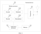
- FIG. 3 is a possible schematic structural diagram of a terminal device in the foregoing communication system.
- the terminal device can perform a method provided in the embodiments of the present invention.
- the terminal device may be any one of the one or more terminal devices in FIG. 1 .
- the terminal device includes a transceiver 301, an application processor (application processor) 302, a memory 303, and a modem processor (modem processor) 304.
- application processor application processor
- modem processor modem processor
- the transceiver 301 may perform adjustment (for example, analog conversion, filtering, amplification, and up-conversion) on the output sample and generate an uplink signal.
- the uplink signal is transmitted by an antenna to the base station in the foregoing embodiment.
- an antenna receives a downlink signal transmitted by a network device.
- the transceiver 301 may perform adjustment (for example, filtering, amplification, down-conversion, and digitization) on a signal received from an antenna and provide an input sample.
- the modem processor 304 sometimes may be referred to as a controller or a processor, and may include a baseband processor (baseband processor, BBP) (not shown).
- BBP baseband processor
- the baseband processor processes a received digital signal, to extract information or data bits transmitted in the signal.
- the BBP is usually implemented in one or more digital signal processors (digital signal processor, DSP) in the modem processor 304 or implemented as a separated integrated circuit (IC).
- DSP digital signal processor
- the modem processor (modem processor) 304 may include an encoder 3041, a modulator 3042, a decoder 3043, and a demodulator 3044.
- the encoder 3041 is configured to encode a to-be-sent signal.
- the encoder 3041 may be configured to receive service data and/or a signaling message that are/is to be sent in an uplink, and perform processing (for example, formatting, encoding, or interleaving) on the service data and the signaling message.
- the modulator 3042 is configured to modulate an output signal of the encoder 3041.
- the modulator may perform processing such as symbol mapping and/or modulation on the output signal (data and/or signaling) of the encoder, and provide an output sample.
- the demodulator 3044 is configured to perform demodulation processing on an input signal. For example, the demodulator 3044 processes an input sample and provides symbol estimation.
- the decoder 3043 is configured to decode a demodulated input signal. For example, the decoder 3043 performs processing such as de-interleaving and/or decoding on the demodulated input signal, and outputs a decoded signal (data and/or signaling).
- the encoder 3041, the modulator 3042, the demodulator 3044, and the decoder 3043 may be implemented by the integrated modem processor 304. These units perform processing based on radio access technologies used by a radio access network.
- the modem processor 304 receives, from the application processor 302, digital data that may represent voice, data, or control information, and processes the digital data for transmission.
- the modem processor may support one or more of a plurality of wireless communication protocols of a plurality of communication systems, for example, LTE, New Radio, Universal Mobile Telecommunications System (Universal Mobile Telecommunications System, UMTS), and High Speed Packet Access (High Speed Packet Access, HSPA).
- the modem processor 304 may include one or more memories.
- the modem processor 304 and the application processor 302 may be integrated on one processor chip.
- the memory 303 is configured to store program code (sometimes also referred to as a program, an instruction, software, or the like) and/or data that are/is used to support communication of the terminal device.
- the memory 203 or the memory 303 may include one or more storage units.
- the storage unit may be a storage unit that is configured to store program code and that is inside the processor 201 or the modem processor 304 or the application processor 302, or may be an external storage unit that is independent of the processor 201 or the modem processor 304 or the application processor 302, or may further be a component that includes a storage unit inside the processor 201 or the modem processor 304 or the application processor 302 and an external storage unit that is independent of the processor 201 or the modem processor 304 or the application processor 302.
- the processor 201 and the modem processor 304 may be processors of a same type or processors of different types.
- the processor 201 and modem processor 304 each may be implemented as a central processing unit (Central Processing Unit, CPU), a general-purpose processor, a digital signal processor (Digital Signal Processor, DSP), an application-specific integrated circuit (Application-Specific Integrated Circuit, ASIC), a field programmable gate array (Field Programmable Gate Array, FPGA), or another programmable logical device, a transistor logic device, a hardware component, another integrated circuit, or any combination thereof.
- CPU Central Processing Unit
- DSP digital signal processor
- ASIC Application-Specific Integrated Circuit
- FPGA Field Programmable Gate Array
- the processor 201 and the modem processor 304 may implement or execute various logical blocks, modules, and circuits as examples that are described with reference to content disclosed in the embodiments of the present invention.
- the processor may also be a combination of devices that implement a computing function, for example, a combination including one or more microprocessors, a combination of a DSP and a microprocessor, or a System-On-a-Chip (system-on-a-chip, SOC).
- sending a downlink (uplink) channel may be sending data or information carried on the downlink (uplink) channel.
- the data or information may be data or information obtained by channel coding.
- NR proposes a concept of a control resource set (Control Resource Set, CORESET) to improve blind detection efficiency of a terminal device.
- a network device allocates one or more control resource sets to each terminal device, and sends a control channel to a terminal device on any control resource set corresponding to the terminal device.
- the terminal device accesses a serving cell and obtains information about a resource block set (RB set) included in a CORESET in a frequency domain.
- the resource block set included in the control resource set is located in a downlink BWP.
- an allocation granularity of the resource block set in a frequency domain is 6 consecutive resource blocks (RB).
- resources occupied by a BWP in a frequency domain may be configured by using dedicated signaling of a terminal device, for example, RRC signaling. No limitation is imposed herein. At most four BWPs can be configured for one terminal device for downlink transmission, and at most four BWPs can further be configured for one terminal device for uplink transmission. Moreover, different terminal devices may have different BWP configurations. In actual transmission, only one uplink/downlink BWP is activated. Resources of a bandwidth part BWP are located in bandwidth of a system carrier. A quantity of physical resource blocks of a common index area included in the system carrier may be determined based on Table 1 below.
- the terminal device determines a subcarrier spacing ⁇ indicated by received indication information, and determines the quantity of the physical resource blocks of the common index area based on ⁇ and Table 1.
- the terminal device receives a notification from the network device to determine the quantity of the physical resource blocks of the common index area or the terminal device determines the quantity of the physical resource blocks of the common index area based on a definition in a standard or a protocol. No limitation is imposed herein. The following uses a table lookup manner as an example for description. Table 1 ⁇ Quantity of physical resource blocks 0 275 1 275 2 275 3 275 4 138 5 69
- ⁇ is corresponding to a size of the subcarrier spacing, as shown in Table 2.
- Common resource block indexes Common RB index
- the common RB indexes are used to configure resources occupied by a BWP in a frequency domain. Resource blocks in one BWP are consecutive in a frequency domain, and a minimum granularity in the frequency domain is one resource block.
- the common RB indexes may be configured by the network device.
- the network device configures an offset from an RB with an index 0 in the common RB indexes to a frequency domain reference point.
- the frequency domain reference point is a frequency domain location that is notified (for example, by using higher layer signaling) by the network device, or is preconfigured or defined.
- the frequency domain reference point may be one of: a physical resource block with a minimum index included in a synchronization signal/physical broadcast channel block (Synchronization signal/Physical broadcast channel Block, SS/PBCH Block) of a primary serving cell (Primary serving cell, Pcell for short), an uplink frequency domain location that is notified by using system information and is in a primary serving cell (Primary serving cell, Pcell), a frequency domain location that is indicated by secondary serving cell configuration information and is in a secondary serving cell (Secondary serving cell, Scell), and a frequency domain area indicated by supplement uplink frequency domain configuration information in supplement uplink (SUL, Supplement Uplink) frequency domain.
- SS/PBCH Block Synchron Generation
- Scell Supplement Uplink
- the network device respectively configures one BWP for each of two terminal devices UE 0 and UE 1, namely, a BWP 0 and a BWP 1.
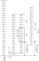
- Resources of the BWP 0 are 14 consecutive frequency domain resource blocks with indexes from ⁇ 1 ⁇ to ⁇ 14 ⁇ in the common RB indexes, to be specific, the resources of the BWP 0 are corresponding to resource blocks corresponding to ⁇ 1, 2, 3, 4, 5, 6, 7, 8, 9, 10, 11, 12, 13, 14 ⁇ in the common RB indexes; resources of the BWP 1 are 12 consecutive frequency domain resource blocks with indexes from ⁇ 12 ⁇ to ⁇ 23 ⁇ in the common RB indexes, to be specific, the resources of the BWP 1 are corresponding to resource blocks corresponding to RB indexes ⁇ 12, 13, 14, 15, 16, 17, 18, 19, 20, 21, 22, 23 ⁇ in the common RB indexes, as shown in FIG.
- BWP RB indexes corresponding to the BWP 1 may also be numbered starting from 0.
- the network device may configure the BWP 0 as a bandwidth part of the UE 0 and the BWP 1 as a bandwidth part of UE 1.
- the BWP 0 and the BWP 1 are two candidate bandwidth parts configured by the network device for a same UE.
- There may be BWP2, BWP3, and more in an actual scenario. No limitation is imposed herein.
- a CORESET resource of only one BWP is configured. The following uses FIG. 5 as an example for description.
- resource indication information is used to indicate a plurality of resource blocks for a terminal device.
- a bitmap manner may be used for indication.
- Each bit in a bitmap is corresponding to 6 resource blocks (an example in which a resource allocation granularity of an RE set is 6 resource blocks is used for description).
- the BWP 0 includes a CORESET 0 and a bitmap of resource allocation indication information is ⁇ ' 100' ⁇ .
- indexes of physical resource blocks in BWP 0 that are included in the CORESET 0 are ⁇ 0, 1, 2, 3, 4, 5 ⁇ .
- the BWP 1 includes a CORESET 1 and a bitmap of resource allocation indication information is ⁇ '11' ⁇ .
- indexes of physical resource blocks in BWP 1 that are included in the CORESET 1 are ⁇ 0, 1, 2, 3, 4, 5, 6, 7, 8, 9, 10, 11 ⁇ .
- Common RB indexes corresponding to RBs with indexes ⁇ 10, 11, 12, 13 ⁇ in the CORESET 0 are the same as common RB indexes corresponding to RBs with indexes ⁇ 0, 1, 2, 3 ⁇ in the CORESET 1, as shown in FIG. 4 . Therefore, in the BWP 0, the RB with indexes ⁇ 10, 11, 12, 13 ⁇ cannot be allocated to the CORESET 0.
- a resource allocation granularity of a CORESET is 6 RBs
- four RBs corresponding to RB indexes ⁇ 6, 7, 8, 9 ⁇ in the BWP 0 cannot meet a size (6 RBs) of the resource allocation granularity, and cannot be used by the CORESET 0 in the BWP 0 or allocated to another BWP for use. Therefore, the RBs with indexes ⁇ 6, 7, 8, 9 ⁇ in the BWP 0 become resource fragments, lowing frequency spectrum utilization.
- start resource block is used in the embodiments of the present invention.
- a meaning of the term may be a resource block corresponding to a minimum subcarrier number in resource blocks included in a specific area (for example, a common index area or a bandwidth part), or a resource block with a minimum number in the included resource blocks numbered from a low frequency to a high frequency; or may be a resource block corresponding to a maximum subcarrier number in resource blocks included in a specific area (for example, a common index area or a bandwidth part), or a resource block with a maximum number in the included resource blocks numbered from a low frequency to a high frequency.
- the low frequency and the high frequency are defined relative to a subcarrier number.
- a subcarrier number of a lower frequency location is smaller than a subcarrier number of a higher frequency location.
- No specific limitation is imposed in the embodiments.
- a specific start resource block depends on a requirement of an actual communication system, a notification from the network device, or a definition in a standard or a protocol.
- a meaning of "1 st bit” is a most significant bit (Most Significant Bit, MSB for short) in a plurality of bits
- a meaning of "2 nd bit” is a most significant bit other than the MSB in the plurality of bits
- a meaning of "last bit” is a least significant bit (Least Significant Bit, LSB for short) in a plurality of bits.
- “1 st “, “2 nd “, and similar expressions are used for ease of solution description.
- a correspondence may exist between any two or more of a frequency domain location of a start resource block of the common index area, a frequency domain location of a frequency domain reference point, a quantity of resource blocks in the common index area, a location of a start resource block of a BWP, a quantity of resource blocks included in a BWP, and a subcarrier spacing.
- the correspondence may be defined in a standard or a protocol, determined by a network device, or obtained by a network device. No limitation is imposed herein. The mapping relationship does not affect implementation of the embodiments of the present invention, and the embodiments of the present invention cover all possibilities.
- start resource blocks in common index areas have a same frequency domain location or different frequency domain locations relative to a frequency domain reference point.
- start resource blocks of a plurality of common index areas where a plurality of BWPs locate are aligned or unaligned in a frequency domain, and subcarrier spacings configured for the plurality of BWPs are the same or different.
- numbers of steps in the embodiments of the present invention do not limit a sequence of a specific execution process.
- An execution sequence of the steps is adaptively adjusted in different optional designs.
- Values of parameters represented by using letters in the embodiments of the present invention are all non-negative integers, in other words, values indicated by the letters are all non-negative integers.
- An embodiment of the present invention provides a communication method.
- a terminal device obtains resource indication information, where the resource indication information indicates a plurality of resource blocks for the terminal device; and the terminal device determines index information of the plurality of resource blocks.
- the network device can efficiently allocate or re-allocate uplink or downlink resources to one or more terminal devices, thereby improving processing efficiency of the terminal device.
- Step 600 A network device determines a plurality of resource blocks, where the plurality of resource blocks are configured for a first terminal device.
- the network device further configures, for a second terminal device, a plurality of resource blocks that do not overlap or that partially overlap with the plurality of resource blocks.
- a terminal device for which the network device configures a plurality of resource blocks is simply expressed as a "terminal device".
- Step 601 The network device sends resource indication information to the terminal device, where the resource indication information is used to indicate the plurality of resource blocks in step 600.
- This step may be performed by a transceiver 202 of the network device, or performed by the transceiver 202 under control of the processor 201 of the network device.
- the resource indication information may include a plurality of bits, which for example, may be a bitmap (bitmap).
- Each of the plurality of bits is used to indicate whether at least one resource block (when the at least one resource block is a plurality of resource blocks, the plurality of resource blocks are consecutive in a frequency domain) is for the terminal device. Specifically, when a value of a bit is 0, the value of the bit is used to indicate that at least one resource block corresponding to the bit cannot be used for the terminal device; or when a value of a bit is 1, the value of the bit is used to indicate that at least one resource block corresponding to the bit can be used for the terminal device.
- bitmap bitmap
- the resource indication information may include a plurality of bits whose bit value is 1. A set of the resource blocks corresponding to these bits is configured for the terminal device.
- a quantity of the plurality of bits included in the resource indication information, a location of at least one resource block corresponding to each bit, and a quantity of resource blocks corresponding to each bit vary with a specific configuration manner.
- the following provides a description as an example.
- the quantity of the bits included in the resource indication information is referred to as S, and S is a positive integer.
- the network device may configure a plurality of groups of candidate resource blocks for each terminal device, for example, configure a plurality of candidate BWPs.
- Each candidate BWP includes a resource block that can be used for the terminal device.
- the plurality of resource blocks mentioned herein may be one of the groups of candidate resource blocks or resource blocks in one of the plurality of candidate BWPs.
- the terminal device determines to send a data channel to the network device by using one of the plurality of groups of candidate resource blocks, or to receive a control channel from or send a control channel to the network device by using one of the plurality of groups of candidate resource blocks.
- the resource indication information is frequency domain resource configuration information of a control resource set CORESET, for example, a resource block set (Resource Block set, RB set); or the resource indication information is frequency domain resource configuration information of a data resource set, for example, frequency domain resource configuration information of a physical uplink shared channel PUSCH and/or a physical downlink shared channel PDSCH.
- a control resource set CORESET for example, a resource block set (Resource Block set, RB set)
- the resource indication information is frequency domain resource configuration information of a data resource set, for example, frequency domain resource configuration information of a physical uplink shared channel PUSCH and/or a physical downlink shared channel PDSCH.
- Step 602 The terminal device obtains the resource indication information, where the resource indication information is used to indicate the plurality of resource blocks for the terminal device.
- the obtaining step may be performed by a transceiver 301 or a processor 304 of the terminal device, or performed by the transceiver 301 under control of the processor 304.
- Step 603 The terminal device determines index information of the plurality of resource blocks.
- the index information may be index information of the plurality of resource blocks in a common index area or index information of the plurality of resource blocks in a bandwidth part.
- the determining step may be performed by the processor 304 of the terminal device.
- the terminal device receives, on the plurality of resource blocks, a control or data channel sent by the network device, or sends, on the plurality of resource blocks, a data channel to the network device.
- the network device can notify the terminal device of allocated or re-allocated uplink or downlink resources by using the resource indication information, so that the terminal device can efficiently obtain locations of the resources in a timely manner, thereby improving processing efficiency of the terminal device.
- the determining operation of the network device may be performed by using the processor 201; the sending and receiving operations of the network device may be performed by using the transceiver 202 or performed by using the transceiver 202 under control of the processor 201; the determining operation of the terminal device may be performed by using the processor 304; the obtaining operation of the terminal device may be performed by using the processor 304 or the transceiver 301 or performed by using the transceiver 301 under control of the processor 304, which specifically depends on an obtaining manner; the sending and receiving operations of the terminal device may be performed by using the transceiver 301.
- resource block indexes of a common index area and a BWP area are independently set, in other words, separately numbered, the resource blocks in both the common index area and the BWP area can be consecutively numbered starting from any number from a start resource block, for example, starting from 0 or starting from 1.
- Embodiment 1 of the present invention imposes no specific limitation. In a specific implementation, numbering mostly starts from 0 as an example.
- indexes of the plurality of resource blocks for the terminal device are configured based on the common RB indexes.
- the common RB index may be used as indexes of one or more BWPs configured in resource blocks of the common index area or a new BWP RB index may be defined as indexes of one or more BWPs configured in resource blocks of the common index area, for example, numbering starts from RBo.
- the indexes of the plurality of resource blocks for the terminal device are configured based on the common RB indexes.
- the method further includes step 6021:
- the terminal device obtains a first offset, where the first offset is an offset between a start resource block of a common index area and a frequency domain reference point, and the offset may be a quantity of RBs offset from the start resource block of a common index area to a frequency domain reference point.
- the frequency domain reference point refer to the description above.
- Different subcarrier spacings may be corresponding to a same first offset or different first offsets. No specific limitation is imposed herein.
- the terminal device further obtains a quantity of the resource blocks of the common index area.
- a quantity of the resource blocks of the common index area refers to the above description of the quantity of the resource blocks in the common index area. No specific limitation is imposed herein.
- the terminal device may obtain the quantity of the resource blocks in any manner.
- the quantity of the resource blocks of the common index area is referred to as X1 in embodiment 1 of the present invention.
- the network device sends the first offset to the terminal device, and the terminal device receives the first offset from the network device, for example, by using higher layer signaling.
- the higher layer signaling may be RRC signaling.
- the terminal device determines the first offset by using a preconfigured table or a correspondence.
- the correspondence may be a correspondence between the first offset and a subcarrier spacing or another correspondence that may be used to obtain the first offset.
- the first offset may be obtained based on an indication or another value corresponding to the first offset.
- the first offset may be a quantity of RBs, that is, the first offset is a quantity of RBs offset from the start resource block of the common index area to the frequency domain reference point.
- the start resource block of the common index area is used as a boundary for alignment in configuration of the plurality of resource blocks.
- the 1 st bit in the S bits is used to indicate whether n resource blocks starting from the start resource block of the common index area are for the terminal device.
- a value of n is equal to m, which is a resource allocation granularity, and may be determined by the network device or notified to the terminal device, or preconfigured. And m is a positive integer.
- an allocation granularity of the RB set for a CORESET in a frequency domain is 6 consecutive RBs. Resources that are less than 6 consecutive RBs cannot be used for RB set resource allocation. In this case, m is equal to 6.
- FIG. 7 is an example for illustrating the foregoing resource configuration manner.
- the plurality of resource blocks for example, 24 RBs
- first four bits in the S bits each indicate 6 consecutive RBs in a frequency domain
- the 1 st bit indicates 6 consecutive RBs starting from the start resource block.
- the quantity of the plurality of resource blocks is not an integer multiple of 6
- a quantity of resource blocks included in a last resource block unit is less than 6.
- a resource block group RBG is used as an allocation granularity for resource configuration of a physical downlink shared channel PDSCH and a physical uplink shared channel PUSCH.
- an RBG size (that is, a quantity of RBs included in each RBG) may be related to BWP bandwidth.
- different BWPs may be corresponding to different RBG sizes.
- the correspondence between an RBG size and BWP bandwidth may be determined by the network device or preconfigured.
- the correspondence may be presented in a form of table, for example, Table 3. Each entry in the table is corresponding to one BWP bandwidth size, for example, a quantity of RBs. Each entry contains two REG size configurations.
- m needs to be determined based on a related parameter such as the BWP bandwidth.
- the network device further needs to determine one of the RBG sizes as m, and notify the terminal device.
- a manner of the notification may be higher layer signaling, for example, RRC signaling.
- m may be 1, 2, 4, 8, 3, 6, or 12.
- the 2 nd bit in the S bits is used to indicate whether m resource blocks are for the terminal device, and the m resource blocks are adjacent to n resource blocks indicated by the 1st in the S bits.
- m resource blocks indicated by the 3 rd bit in the S bits are adjacent to m resource blocks indicated by the 2 nd bit.
- S may be either of the following:
- m consecutive RBs starting from the start resource block of the common index area may be used as one resource block unit for resource configuration.
- the network device can configure resources for a plurality of terminal devices in a manner of aligning boundaries of resource block units, to be specific, try to use m RBs as a unit to perform resource configuration for a plurality of terminal devices or a plurality of resources, to ensure that resource blocks configured for the terminal devices are aligned at boundaries relative to the start RB by using m resource blocks as a resource block unit, in other words, to ensure that a quantity of RBs offset between a boundary of each resource block unit configured for the terminal devices and the start RB is a multiple of m, so as to as far as possible avoid resource block fragments (a fragment of RBs less than m) that cannot be allocated, thereby improving resource utilization efficiency.
- the boundary may be at least one of a low frequency boundary resource block and a high frequency boundary resource block of the resource block unit.
- resource block unit division in embodiment 1 of the present invention is merely logical division, and is not presented in physical resources.
- the frequency domain reference point is used as a boundary for alignment in configuration of the plurality of resource blocks.
- the 1 st bit in the S bits is used to indicate whether n resource blocks starting from the start resource block of the common index area are for the terminal device, n is determined based on the first offset and m, and n is greater than 0.
- n is determined based on the first offset and m, and n is greater than 0.
- n is determined based on the first offset and m, n is equal to y1, or n is equal to m minus y1, wherein y1 is equal to a value of the first offset mod m, that is, the first offset mod m.
- the first offset is an offset from the start resource block RB towards a low frequency direction relative to the frequency domain reference point
- n is equal to y1; or if y1 is equal to 0, n is equal to m minus y1.
- the 1 st bit indicates y1 resource blocks starting from the start RB, and resource configuration is performed by trying to use m RBs as a resource block unit starting from a (y1 + 1) th resource block, so that the frequency domain reference point is located at a logical boundary for resource block unit allocation.
- n is equal to m minus y1, wherein y1 is equal to the first offset mod m, that is, the first offset mod m.
- the 1 st bit indicates (m - y1) resource blocks starting from the start RB, and the (m - y1) resource blocks and y1 RB fragments in the first offset can form a resource block unit of m resource blocks in terms of quantity, so that the frequency domain reference point is located at a logical boundary for resource block unit allocation.
- the 2 nd bit in the S bits is used to indicate whether m resource blocks are for the terminal device, and the m resource blocks are adjacent to n resource blocks indicated by the 1st bit in the S bits.
- m resource blocks indicated by the 3 rd bit in the S bits are adjacent to m resource blocks indicated by the 2 nd bit.
- S may be any one of the following, and specifically depends on a requirement or configuration of an actual communication scenario:
- a difference between this possible implementation and the first possible implementation lies in an alignment location.
- the start RB in the common index area is used as the alignment location.
- the frequency domain reference point is used as the alignment location.
- processing manners are similar.
- the frequency domain reference point may be used as a boundary for resource block unit configuration.
- the network device can configure resources for a plurality of terminal devices in a manner of aligning boundaries of resource block units, to be specific, use the frequency domain reference point as a resource block unit boundary for resource configuration performed by using m RBs as a unit, to ensure that resource blocks configured for each terminal device are aligned at a boundary relative to the frequency domain reference point by using m resource blocks as a resource block unit, in other words, to ensure that a quantity of RBs offset from a boundary of each resource block unit configured for the terminal devices to the frequency domain reference point is a multiple of m, so as to avoid as far as possible resource block fragments (a fragment of RBs less than m) that cannot be allocated, thereby improving resource utilization efficiency.
- the boundary may be at least one of a low frequency boundary resource block and a high frequency boundary resource block of the resource block unit.
- the determining, by the terminal device, index information of the plurality of resource blocks in step 603 is performed by using offset indication information.
- the method further includes step 6023:
- the network device sends offset indication information to the terminal device, and the terminal device obtains the offset indication information.
- the offset indication information is used to indicate a quantity Q of RBs offset from a resource indication reference resource block to the start resource block of the common index area.
- the resource indication reference resource block may be determined by the network device, or defined by a protocol or a standard, or preconfigured, and may be the 1 st RB or the last RB in at least one resource block indicated by the 1 st bit in the resource indication information.
- “1 st " and “last” may be “1 st “ and “last” of low frequency locations or "1 st " and “last” of high frequency locations.
- a configuration of the resource indication reference resource block is used by the terminal device to determine the index information of the plurality of resource blocks.
- the quantity Q of RBs offset from a resource indication reference resource block to the start resource block of the common index area is used to indicate Q consecutive resource blocks starting from the start resource block of the common index area towards a high frequency direction, for example, indicate Q consecutive resource blocks RB 0 , RB 1 , ..., RB m-1 in the common index area when resource blocks are numbered from 0.
- Q is greater than or equal to 0 and less than m. For m, refer to the description above.
- the resource indication reference resource block is the last RB in the at least one resource block indicated by the 1 st bit in the resource indication information
- the 1 st bit in the S bits is corresponding to Q consecutive resource blocks starting from the start RB, and Q is not equal to 0.
- the resource indication reference resource block is the 1 st RB in the at least one resource block indicated by the 1 st bit in the resource indication information
- the 1 st bit in the S bits is corresponding to m consecutive resource blocks starting from the start resource block of the common index area; or if Q is not equal to 0, the 1 st bit in the S bits is corresponding to m consecutive resource blocks adjacent to Q consecutive resource blocks starting from the start resource block of the common index area.
- the 2 nd bit in the S bits is corresponding to m resource blocks adjacent to resource blocks corresponding to the 1 st bit in the common index area.
- the offset indication information is carried in downlink control information DCI or higher layer signaling, and is notified by the network device to the terminal device, or is pre-notified by the network device to the terminal device and stored by the terminal device.
- the offset indication information may be a plurality of bits, and a value indicated by the plurality of bits represents a quantity of offset RBs, as described in Table 4 below.
- Table 4 Offset indication information Offset 000 0 RBs 001 1 RB 010 2 RBs 011 3 RBs 100 4 RBs 101 5 RBs
- the network device in addition to sending the resource indication information to the terminal device, the network device further indicates, to the terminal device, location information of a part of resource blocks indicated by the resource indication information, so that the terminal device can accurately and efficiently obtain resource configuration information, thereby improving processing efficiency of the terminal device.
- the plurality of resource blocks for the terminal device are configured based on a resource block index (RB index) of the BWP.
- RB index resource block index
- the method further includes step 6021 in the first optional design.
- step 6021 in the first optional design.
- the method further includes step 6022: The terminal device obtains a second offset, where the second offset is an offset between the start resource block of the common index area and a start resource block of the carrier bandwidth part BWP, and the offset may be a quantity of RBs offset from the start resource block of the common index area to a start resource block of the carrier bandwidth part BWP.
- the terminal device further obtains a quantity of resource blocks in the BWP.
- the quantity of the resource blocks in the BWP may be determined through a lookup table, or determined by receiving a notification of the network device, or determined based on a definition in a standard or a protocol. No limitation is imposed herein.
- the quantity of the resource blocks in the BWP may be indicated by using higher layer signaling, for example, RRC signaling.
- the quantity of the resource blocks in the BWP is referred to as X2 in embodiment 1 of the present invention.
- the network device sends the second offset to the terminal device, and the terminal device receives the second offset from the network device, for example, by using higher layer signaling.
- the higher layer signaling may be RRC signaling.
- the terminal device determines the second offset by using a preconfigured table or a correspondence.
- the correspondence may be a correspondence between the second offset and a subcarrier spacing or another correspondence that may be used to obtain the second offset.
- the second offset may further be obtained based on an indication or another value corresponding to the second offset. No limitation is imposed herein.
- the second offset may be a quantity of RBs, to be specific, the second offset is a quantity of RBs offset from the start resource block of the BWP to the start resource block of the common index area.
- the start resource block of the common index area is used as a boundary for alignment in configuration of the plurality of resource blocks.
- the 1 st bit in the S bits is used to indicate whether n consecutive resource blocks starting from the start resource block of the bandwidth part BWP are for the terminal device, or is used to indicate whether m resource blocks adjacent to n consecutive resource blocks starting from the start resource block of the bandwidth part BWP are for the terminal device, n is determined based on m and the second offset, and n is greater than 0.
- m refer to the description above. Details are not described herein again.
- Frequency domain resources in the BWP are a part of or all resource blocks of frequency domain resources in the common index area.
- the second offset is an offset from the start resource block of the BWP towards a high frequency direction to the start RB in the common index area.
- n is equal to m minus y2
- y2 is equal to a value of the second offset mod m, that is, the second offset mod m.
- the 1 st bit in the S bits is used to indicate whether n consecutive resource blocks starting from the start resource block of the bandwidth part BWP are for the terminal device.
- the 1 st bit in the S bits is used to indicate whether m resource blocks adjacent to n consecutive resource blocks starting from the start resource block of the bandwidth part BWP are for the terminal device.
- the 1 st bit in the S bits is used to indicate whether n consecutive resource blocks starting from the start resource block of the bandwidth part BWP are for the terminal device.
- a BWP 0 and a BWP 1 configured by the network device for at least one terminal device are both located in resource blocks in the common index area.
- a start location of the BWP 0 is 1 RB offset from the start resource block in the common index area towards the high frequency direction
- a start location of the BWP 1 is 4 RB offset from the start resource block in the common index area towards the high frequency direction.
- To use the start resource block of the common index area as a boundary for resource block unit configuration starting from the start resource block of the BWP 0, first five RBs RB 0 -RB 4 are used as one resource block unit, RB 5 -RB 10 are used as one resource block unit, and so on.
- a quantity of RBs offset from the start resource block RB 5 of the 2 nd resource block unit in the BWP to the start resource block of the common index area is an integer multiple of 6.
- a quantity of RBs offset from a start resource block RB 11 of the 3 rd resource block unit in the BWP 0 to the start resource block of the common index area is also an integer multiple of 6.
- RB 0 and RB 1 in the BWP 1 are used as one resource block unit.
- the network device may configure more BWPs in addition to the BWP 0 and the BWP 1, it can be ensured that there are as few resource fragments as possible in an overlapped part of the plurality of BWPs, because a quantity of RBs offset from a start or last resource block of each resource block unit to the start resource block RB in the common index area is an integer multiple of m.
- the 2 nd bit in the S bits is used to indicate whether m resource blocks are for the terminal device, and the m resource blocks are adjacent to n resource blocks indicated by the 1 st bit in the S bits.
- m resource blocks indicated by a 3 rd bit in the S bits are adjacent to m resource blocks indicated by the 2 nd bit.
- S may be any one of the following:
- the start resource block of the common index area may be used as a boundary for resource block unit configuration.
- the network device can configure resources for a plurality of terminal devices in a manner of aligning boundaries of resource block units, to be specific, use m RBs as a unit to perform resource configuration, to ensure that resource blocks configured for the terminal devices are aligned at boundaries relative to the start RB by using m resource blocks as a resource block unit, in other words, to ensure that a quantity of offset RBs between a boundary of each resource block unit configured for the terminal devices and the start RB is a multiple of m, so as to avoid as far as possible resource block fragments (a fragment of RBs less than m) that cannot be allocated, thereby improving resource utilization efficiency.
- the boundary may be at least one of a low frequency boundary resource block and a high frequency boundary resource block of the resource block unit.
- the frequency domain reference point is used as a boundary for alignment in configuration of the plurality of resource blocks.
- a 1 st bit in the S bits is used to indicate whether n consecutive resource blocks starting from the start resource block of the bandwidth part BWP are for the terminal device, or is used to indicate whether m resource blocks adjacent to n consecutive resource blocks starting from the start resource block of the bandwidth part BWP are for the terminal device, n is determined based on m and a third offset, and n is greater than 0.
- m refer to the description above. Details are not described herein again.
- n is equal to y3 or is equal to a difference between m and y3, wherein y3 is equal to a value of the third offset mod m.
- the third offset is related to the first offset and the second offset. Specifically, the third offset is an offset between the start resource block of the BWP and the frequency domain reference point. Alternatively, the third offset may further be obtained based on an indication or another value corresponding to the third offset, instead of being determined based on the first offset and the second offset.
- the third offset may be a quantity of offset RBs.
- the third offset is a quantity of RBs offset from the start resource block of the BWP to the frequency domain reference point.
- a 2 nd bit in the S bits is used to indicate whether m resource blocks are for the terminal device, and the m resource blocks are adjacent to n resource blocks indicated by the 1 st bit in the S bits.
- “adjacent” is “adjacent in the high frequency direction”.
- m resource blocks indicated by a 3 rd bit in the S bits are adjacent to m resource blocks indicated by the 2 nd bit.
- S may be any one of the following:
- the frequency domain reference point may be used as a boundary for resource block unit configuration.
- the network device can configure resources for a plurality of terminal devices in a manner of aligning boundaries of resource block units, to be specific, use the frequency domain reference point as a boundary for resource configuration performed by using m RBs as a unit, to ensure that resource blocks configured for each terminal device are aligned at a boundary relative to the frequency domain reference point by using m resource blocks as a resource block unit, in other words, to ensure that a quantity of RBs offset between a boundary of each resource block unit configured for the terminal devices and the frequency domain reference point is a multiple of m, so as to as far as possible avoid resource block fragments (a fragment of RBs less than m) that cannot be allocated, thereby improving resource utilization efficiency.
- the boundary may be at least one of a low frequency boundary resource block and a high frequency boundary resource block of the resource block unit.
- the determining, by the terminal device, index information of the plurality of resource blocks in step 603 is performed by using offset indication information.
- the method further includes step 6023:
- the network device sends offset indication information to the terminal device, and the terminal device obtains the offset indication information.
- the offset indication information is used to indicate a quantity Q of RBs offset from a resource indication reference resource block to the start resource block of the common index area or the start resource block of the BWP.
- the quantity Q of offset RBs is used to indicate Q consecutive resource blocks starting from the start resource block of the common index area or the start resource block of the BWP, for example, indicate Q consecutive resource blocks RB 0 , RB 1 , ..., RB m - 1 starting from the start resource block of the common index area or the start resource block of the BWP.
- Q is greater than or equal to 0 and less than m. For m, refer to the description above.
- the resource indication reference resource block is a first RB in at least one resource block indicated by the 1 st bit in the resource indication information
- the 1 st bit in the S bits is corresponding to m consecutive resource blocks starting from the start resource block of the common index area or the start resource block of the BWP
- Q is 0.
- the network device configures the resource blocks for the terminal device based on a BWP resource block index RB index.
- the terminal device determines the index information of the plurality of resource blocks by using the offset indication information and the second offset.
- a 2 nd bit in the S bits is corresponding to m resource blocks adjacent to resource blocks corresponding to the 1 st bit in the common index area or the BWP.
- the offset indication information is carried in downlink control information DCI or higher layer signaling, and is notified by the network device to the terminal device, or is pre-notified by the network device to the terminal device and stored by the terminal device.
- the offset indication information may be a plurality of bits, and a value indicated by the plurality of bits represents a quantity of offset RBs, as described in Table 4.
- the network device in addition to sending the resource indication information to the terminal device, the network device further indicates, to the terminal device, a start location of some of resource blocks indicated by the resource indication information, so that the terminal device can efficiently obtain resource configuration information, thereby improving processing efficiency of the terminal device.
- the network device configures, based on the common RB index, the resource blocks for the terminal device.
- the method further includes step 6022 in the second optional design.
- step 6022 in the second optional design.
- the terminal device further obtains a quantity X1 of resource blocks in the common index area and a quantity X2 of resource blocks in the BWP.
- X1 and X2 refer to the description above. Meanings of X1 and X2 are the same as those described above.
- a 1 st bit in the S bits is used to indicate whether n resource blocks starting from the start resource block of the BWP are for the terminal device, or is used to indicate whether m resource blocks adjacent to n consecutive resource blocks starting from the start resource block of the bandwidth part BWP are for the terminal device.
- An index of the start resource block of the BWP uses an index of a resource block of the common index area, and is determined based on an index of the start resource block of the common index area and a second offset, n is determined based on the second offset and m, and n > 0.
- m refer to the description above. Details are not described herein again.
- Frequency domain resources in the BWP are some or all resource blocks of frequency domain resources in the common index area.
- the second offset is an offset of the start resource block of the BWP in a high frequency direction relative to the start resource block of the common index scheme.
- a second bit in the S bits is used to indicate whether m resource blocks are for the terminal device, and the m resource blocks are adjacent to n resource blocks indicated by the 1 st bit in the S bits.
- S may be any one of the following:
- the start resource block of the common index area may be used as a boundary for resource block unit configuration.
- the network device can configure resources for a plurality of terminal devices in a manner of aligning boundaries of resource block units, to be specific, use m RBs as a unit to perform resource configuration, to ensure that resource blocks configured for the terminal devices are aligned at boundaries relative to the start resource block by using m resource blocks as a resource block unit, in other words, to ensure that a quantity of offset RBs between a boundary of each resource block unit configured for the terminal devices and the start RB is a multiple of m, so as to avoid as far as possible resource block fragments (a fragment of RBs less than m) that cannot be allocated, thereby improving resource utilization efficiency.
- the boundary may be at least one of a low frequency boundary resource block and a high frequency boundary resource block of the resource block unit.
- a 1 st bit in the S bits is used to indicate whether n resource blocks starting from the start resource block of the BWP are for the terminal device, or is used to indicate whether m resource blocks adjacent to n consecutive resource blocks starting from the start resource block of the bandwidth part BWP are for the terminal device.
- An index of the start resource block of the BWP uses an index of a resource block of the common index area, and is determined based on an index of the start resource block of the common index area and the second offset, n is determined based on m and a third offset, and n is greater than 0.
- m refer to the description above. Details are not described herein again.
- n is equal to y3 or is equal to a difference between m and y3, wherein y3 is equal to a value of the third offset mod m.
- the third offset is related to the first offset and the second offset. Specifically, the third offset is an offset that is between the start resource block R0 of the BWP and the frequency domain reference point and that is obtained based on the first offset and the second offset. Alternatively, the third offset may further be obtained based on an indication or another value corresponding to the third offset, instead of being determined based on the first offset and the second offset.
- the third offset may be a quantity of offset RBs.
- the third offset is a quantity of RBs offset from the start resource block R0 in the BWP to the frequency domain reference point.
- n is equal to the difference obtained by subtracting y3 from m, that is (m - y3), wherein y3 is equal to a value of the third offset mod m, that is, the third offset mod m.
- the 1 st bit indicates (m - y3) resource blocks starting from the start resource block of the BWP, and the (m - y3) resource blocks and y3 RB fragments in the third offset can form a resource block unit of m resource blocks in terms of quantity, so that the frequency domain reference point is located at a logical boundary for resource block unit allocation.
- y3 refers to the description of the second possible implementation in the second optional design.
- a second bit in the S bits is used to indicate whether m resource blocks are for the terminal device, and the m resource blocks are adjacent to n resource blocks indicated by the 1 st bit in the S bits.
- "adjacent" is "adjacent in the high frequency direction”.
- m resource blocks indicated by a 3 rd bit in the S bits are adjacent to m resource blocks indicated by the second bit.
- “adjacent” is “adjacent in the high frequency direction”.
- the frequency domain reference point may be used as a boundary for resource block unit configuration.
- the network device can configure resources for a plurality of terminal devices in a manner of aligning boundaries of resource block units, to be specific, use the frequency domain reference point as a boundary for resource configuration performed by using m RBs as a unit, to ensure that resource blocks configured for each terminal device are aligned at a boundary relative to the frequency domain reference point by using m resource blocks as a resource block unit, in other words, to ensure that a quantity of offset RBs between a boundary of each resource block unit configured for the terminal devices and the frequency domain reference point is a multiple of m, so as to avoid as far as possible resource block fragments (a fragment of RBs less than m) that cannot be allocated, thereby improving resource utilization efficiency.
- the boundary may be at least one of a low frequency boundary resource block and a high frequency boundary resource block of the resource block unit.
- Embodiment 2 of the present invention provides a control resource set determining method, so that when a plurality of control resource sets overlap on time-frequency resources, a resource blocking probability of a control channel included by each of the control resource sets is minimized.
- Step 0 A network device determines a plurality of control resource sets, where each control resource set is corresponding to one mapping manner of a control channel element.
- a terminal device determines the plurality of control resource sets, where each control resource set is corresponding to one mapping manner of a control channel element.
- step 0 may be performed by the processor 304 of the terminal device shown in FIG. 3 or the processor 201 of the network device shown in FIG 2 .
- Step 1 The terminal device detects, in the control channel resource set, a control channel carrying control information.
- step 1 may be performed by the processor 304 of the terminal device shown in FIG. 3 .
- the control channel includes a plurality of control channel elements (Control Channel Element, CCE).
- the control channel element includes a plurality of REG bundles (REG bundle).
- a REG bundle set included by a control channel element j is ⁇ f ( 6j / L ), f ( 6j / L +1),..., f ( 6j / L + 6 / L -1) ⁇ ;
- ⁇ x rC + c + n shift mod N RB CORESET N symb CORESET / L
- the method further includes step 2: The terminal device obtains an offset, where the offset is used for mapping of the control channel element, and the offset may be determined based on higher layer signaling or determined based on an identifier configured by using higher layer signaling.
- a beneficial effect of the method is as follows: No matter what a configured value of n ID is, it can be ensured that a CCE mapped to a control resource set is offset in a frequency domain in a granularity of 6 consecutive RBs. In this way, when a plurality of control resource sets overlap on time-frequency resources, a resource blocking probability of a control channel included by each of the control resource sets is minimized.
- the obtaining step and the higher layer signaling receiving step of the terminal device in the foregoing steps may be performed by a receiver 301A in the terminal device in FIG. 3 .
- the sending step of the network device may be performed by a transmitter 202B in FIG. 2 .
- the network elements such as the network device and the terminal device include corresponding hardware structures and/or software modules for executing the functions.
- the network elements such as the network device and the terminal device include corresponding hardware structures and/or software modules for executing the functions.
- a person of ordinary skill in the art should easily be aware that, in combination with the examples described in the embodiments disclosed in this specification, units, algorithms steps may be implemented by hardware or a combination of hardware and computer software. Whether a function is performed by hardware or hardware driven by computer software depends on particular applications and design constraints of the technical solutions. A person skilled in the art may use different methods to implement the described functions for each particular application, but it should not be considered that the implementation goes beyond the scope of the present invention.
- the terminal device can execute any method in the embodiments of the present invention.
- the terminal device may include at least a transceiver 301 and a processor 304 (a superordinate expression of processor is used herein, and the processor 304 may represent a modem processor 304 or an integration of the modem processor 304 and an application processor 302).
- the terminal device may further include other components in FIG. 3 and the description about FIG. 3 , such as a memory.
- the transceiver 301 may be constituted by an independent receiver and an independent transmitter, to separately execute corresponding receiving and sending functions; or may be a transceiver that integrates the receiving and sending functions.
- the transceiver 301 in FIG. 3 may be structurally split into a receiver 301A and a transmitter 301B.
- the terminal device is used only as an optional main body for a description as an example herein.
- the following provides a description by using a wireless apparatus as a main body.
- the wireless apparatus may be a unit, a chip, or a part included by the terminal device, or may be the terminal device itself.
- the wireless apparatus includes a processor 304 and a receiver 301A.
- the receiver 301A is configured to obtain resource indication information, where the resource indication information is used to indicate a plurality of resource blocks for the terminal device.
- the processor 304 is configured to determine index information of the plurality of resource blocks.
- the resource indication information includes S bits, and each of the S bits is used to indicate whether at least one resource block is for the terminal device.
- a 1 st bit in the S bits is used to indicate whether n consecutive resource blocks starting from a start resource block of a common index area are for the terminal device, and n is equal to m; or n is equal to a value determined based on a first offset and m; where m is notified by a network device or preconfigured, the first offset is an offset between the start resource block of the common index area and a frequency domain reference point, and the frequency domain reference point is notified by the network device or preconfigured.
- n is equal to the value determined based on the first offset and m
- n is equal to y1
- n is equal to m minus y 1
- y 1 is equal to a value of the first offset mod m.
- the receiver 301A is further configured to obtain the first offset from the network device.
- a 1 st bit in the S bits is used to indicate whether n consecutive resource blocks starting from a start resource block of a bandwidth part BWP are for the terminal device, or is used to indicate whether m resource blocks adjacent to n consecutive resource blocks starting from a start resource block of a bandwidth part BWP are for the terminal device;
- n when n is equal to the value determined based on m and the second offset, n is equal to m minus y2, and y2 is equal to a value of the second offset mod m; or when n is equal to the value determined based on m, the first offset, and the second offset, n is equal to y3, or n is equal to a difference between m and y3, where y3 is equal to a value of a third offset mod m, and the third offset is related to the first offset and the second offset.
- the receiver 301A is further configured to obtain the first offset and/or the second offset from the network device.
- the receiver 301A or the processor 304 obtains offset indication information, where the offset indication information is used to indicate a quantity of RBs offset from a resource indication reference resource block to the start resource block of the common index area or the start resource block of the carrier bandwidth part BWP.
- the resource indication reference resource block may be a first RB or a last RB in the at least one resource block indicated by the 1 st bit in the resource indication information.
- the processor 304 determines the index information of the plurality of resource blocks based on the offset indication information and the resource indication information.
- a second bit in the S bits is used to indicate whether m resource blocks are for the terminal device, and the m resource blocks are adjacent, in a frequency domain, to n resource blocks indicated by the 1 st bit in the S bits.
- m is equal to 1, 2, 4, 8, 3, 6, or 12.
- the wireless apparatus includes a processor 304 and a receiver 301A, to execute any method provided in embodiment 2 of the present invention.
- a corresponding part in the foregoing embodiments may be implemented by corresponding hardware, or may be implemented by the corresponding hardware by executing corresponding software.
- the receiver 301A may be hardware that has a function of executing the receiving function, such as a transceiver that integrates the sending and receiving functions or a receiver that implements only the receiving function, or may be a general processor or another hardware device that can execute a corresponding computer program to complete the foregoing functions, or may be a software module or a functional unit that executes a corresponding function, such as a receiving unit.
- the processor 304 may be hardware that is capable of executing the processor function, such as a processor with a specific function or a general processor, or may be another hardware device that can execute a corresponding computer program to complete the foregoing functions, or may be a software module or a functional unit that executes a corresponding function, such as a processing unit.
- the transmitter 301B may be hardware that has a function of executing the sending function, such as a transceiver that integrates the sending and receiving functions or a transmitter that implements only the transmitting function, or may be a general processor or another hardware device that can execute a corresponding computer program to complete the foregoing functions, or may be a software module or a functional unit that executes a corresponding function, such as a transmitting unit.
- the wireless apparatus further includes a storage unit. For details, refer to FIG. 9 .
- the network device can execute any method in the embodiments of the present invention.
- the network device may include at least a controller or processor 201 (the following uses the processor 201 as an example for description) and a transceiver 202.
- the network device may further include other components in FIG. 2 and the description about FIG. 2 , such as a memory.
- the transceiver 202 may be constituted by an independent receiver and an independent transmitter, to separately execute corresponding receiving and sending functions; or may be a transceiver that integrates the receiving and sending functions. No further limitation is imposed herein.
- the network device 2 may be structurally split into a receiver 202A and a transmitter 202B.
- the network device is used only as an optional main body for a description as an example herein. The following provides a description by using a wireless apparatus as a main body.
- the wireless apparatus may be a unit, a chip, or a part included by the network device, or may be the network device itself.
- the wireless apparatus includes a processor 201 and a transmitter 202B.
- the processor is configured to determine a plurality of resource blocks, where the plurality of resource block units are for a terminal device.
- the transmitter is configured to send resource indication information to the terminal device, where the resource indication information is used to indicate the plurality of resource blocks.
- the resource indication information includes S bits, and each of the S bits is used to indicate whether at least one resource block is for the terminal device.
- a 1 st bit in the S bits is used to indicate whether n consecutive resource blocks starting from a start resource block of a common index area are for the terminal device, and n is equal to m; or n is equal to y1; or n is equal to m minus y1; where y1 is equal to a value of a first offset mod m, m is determined by the network device or preconfigured, the first offset is an offset between the start resource block of the common index area and a frequency domain reference point, and the frequency domain reference point is determined by the network device or preconfigured.
- the transmitter 202B is further configured to send the first offset to the terminal device.
- a 1 st bit in the S bits is used to indicate whether n consecutive resource blocks starting from a start resource block of a bandwidth part BWP are for the terminal device, or is used to indicate whether m resource blocks adjacent to n consecutive resource blocks starting from a start resource block of a bandwidth part BWP are for the terminal device;
- the transmitter 202B is further configured to send the second offset to the terminal device.
- the transmitter 202B sends offset indication information to the terminal device, where the offset indication information is used to indicate a quantity of RBs offset from a resource indication reference resource block to the start resource block of the common index area or the start resource block of the carrier bandwidth part BWP.
- the resource indication reference resource block may be a first RB or a last RB in the at least one resource block indicated by the 1 st bit in the resource indication information.
- a second bit in the S bits is used to indicate whether m resource blocks are for the terminal device, and the m resource blocks are adjacent, in a frequency domain, to n resource blocks indicated by the 1 st bit in the S bits.
- m is equal to 1, 2, 4, 8, 3, 6, or 12.
- a corresponding part in the foregoing embodiments may be implemented by corresponding hardware, or may be implemented by the corresponding hardware by executing corresponding software.
- the transmitter 202B may be hardware that has a function of executing the sending function, such as a transceiver that integrates the sending and receiving functions or a transmitter that implements only the sending function, or may be a general processor or another hardware device that can execute a corresponding computer program to complete the foregoing functions, or may be a software module or a functional unit that executes a corresponding function, such as a transmitting unit.
- the processor 201 may be hardware that is capable of executing the processor function, such as a processor with a specific function or a general processor, or may be another hardware device that can execute a corresponding computer program to complete the foregoing functions, or may be a software module or a functional unit that executes a corresponding function, such as a processing unit.
- the receiver 202A may be hardware that has a function of executing the receiving function, such as a transceiver that integrates the sending and receiving functions or a receiver that implements only the receiving function, or may be a general processor or another hardware device that can execute a corresponding computer program to complete the foregoing functions, or may be a software module or a functional unit that executes a corresponding function, such as a receiving unit.
- the wireless apparatus further includes a storage unit. For details, refer to FIG. 9 .
- the accompanying drawings show only a simplified design of the wireless apparatus.
- the wireless apparatus may include any quantities of transmitters, receivers, processors, controllers, memories, communication units, and the like.
- An embodiment of the present invention further provides a communication system, including at least one network device and at least one terminal device described for executing the embodiments of the present invention.
- An embodiment of the present invention further provides an apparatus (for example, an integrated circuit, a wireless device, and a circuit module), configured to implement the foregoing communication method.
- An apparatus for implementing a power tracker and/or a power generator described in this specification may be a standalone device or may be a part of a larger device.
- the device may be (i) a standalone IC; (ii) a set of one or more ICs, including a memory IC for storing data and/or an instruction; (iii) an RFIC, such as an RF receiver or an RF transmitter/receiver; (iv) an ASIC, such as a mobile station modem; (v) a module that can be built into other devices; (vi) a receiver, a cellular phone, a wireless device, a handheld phone, or a mobile unit; (vii) others.
- the method and the apparatus provided in the embodiments of the present invention may be applied to the terminal device or the network device (which may be collectively referred to as a wireless device).
- the terminal device or the network device or the wireless device may include a hardware layer, an operating system layer running on the hardware layer, and an application layer running on the operating system layer.
- the hardware layer includes hardware such as a central processing unit (central processing unit, CPU), a memory management unit (memory management unit, MMU), and a memory (also referred to as a main memory).
- the operating system may be any one or more computer operating systems that implement service processing in a process (process), such as a Linux operating system, a Unix operating system, an Android operating system, an iOS operating system, or a Windows operating system.
- the application layer includes applications such as a browser, an address book, text processing software, and instant messaging software.
- a specific structure of a method execution body is not limited in the embodiments of the present invention, provided that the method execution body can perform communication based on the signal transmission method in the embodiments of the present invention by running a program that records code of the method in the embodiments of the present invention.
- the wireless communication method in the embodiments of the present invention may be performed by the terminal device, or the network device, or a function module that is in the terminal device or the network device and that can call and execute a program.
- aspects or features in the embodiments of the present invention may be implemented as a method, an apparatus or a product that uses standard programming and/or engineering technologies.
- product used in this application covers a computer program that can be accessed from any computer readable component, carrier or medium.
- the computer-readable medium may include but is not limited to: a magnetic storage component (for example, a hard disk, a floppy disk or a magnetic tape), an optical disc (for example, a compact disc (compact disc, CD), a digital versatile disc (digital versatile disc, DVD), a smart card and a flash memory component (for example, erasable programmable read-only memory (erasable programmable read-only memory, EPROM), a card, a stick, or a key drive).
- various storage media described in this specification may indicate one or more devices and/or other machine-readable media that is used to store information.
- the term "machine readable media” may include but is not limited to a radio channel, and various other media that can store, contain and/or carry an instruction and/or data.
- All or some of the foregoing embodiments may be implemented by using software, hardware, firmware, or any combination thereof.
- the embodiments may be implemented fully or partially in a form of a computer program product.
- the computer program product includes one or more computer instructions.
- the computer may be a general-purpose computer, a special-purpose computer, a computer network, or other programmable apparatuses.
- the computer instructions may be stored in a computer-readable storage medium or may be transmitted from a computer-readable storage medium to another computer-readable storage medium.
- the computer instructions may be transmitted from a website, computer, server, or data center to another website, computer, server, or data center in a wired (for example, a coaxial cable, an optical fiber, or a digital subscriber line (DSL)) or wireless (for example, infrared, radio, and microwave, or the like) manner.
- the computer-readable storage medium may be any usable medium accessible by a computer, or a data storage device, such as a server or a data center, integrating one or more usable media.
- the usable medium may be a magnetic medium (for example, a floppy disk, a hard disk, or a magnetic tape), an optical medium (for example, a digital versatile disc (DVD)), a semiconductor medium (for example, a Solid State Disk (SSD)), or the like.
- a magnetic medium for example, a floppy disk, a hard disk, or a magnetic tape
- an optical medium for example, a digital versatile disc (DVD)
- DVD digital versatile disc
- semiconductor medium for example, a Solid State Disk (SSD)
- the disclosed system, apparatus, and method may be implemented in other manners.
- the described apparatus embodiment is merely an example.
- the unit division is merely logical function division and may be other division in actual implementation.
- a plurality of units or components may be combined or integrated into another system, or some features may be ignored or not performed.
- the displayed or discussed mutual couplings or direct couplings or communication connections may be implemented by using some interfaces.
- the indirect couplings or communication connections between the apparatuses or units may be implemented in electronic, mechanical, or other forms.
- the units described as separate parts may or may not be physically separate, and parts displayed as units may or may not be physical units, may be located in one position, or may be distributed on a plurality of network units. Some or all of the units may be selected based on actual requirements to achieve the objectives of the solutions of the embodiments.
- the functions When the functions are implemented in the form of a software functional unit and sold or used as an independent product, the functions may be stored in a computer-readable storage medium. Based on such an understanding, the technical solutions of the embodiments of the present invention essentially, or the part contributing to the prior art, or some of the technical solutions may be implemented in a form of a software product.
- the software product is stored in a storage medium, and includes several instructions for instructing a computer device (which may be a personal computer, a server, or a network device) to perform all or some of the steps of the methods described in the embodiments of the present invention.
- the foregoing storage medium includes: any medium that can store program code, such as a USB flash drive, a removable hard disk, a read-only memory (ROM, Read-Only Memory), a random access memory (RAM, Random Access Memory), a magnetic disk, or an optical disc.
- program code such as a USB flash drive, a removable hard disk, a read-only memory (ROM, Read-Only Memory), a random access memory (RAM, Random Access Memory), a magnetic disk, or an optical disc.
Landscapes
- Engineering & Computer Science (AREA)
- Signal Processing (AREA)
- Computer Networks & Wireless Communication (AREA)
- Mobile Radio Communication Systems (AREA)
Claims (21)
- Kommunikationsverfahren, das Folgendes umfasst:Erhalten, durch eine Endgerätevorrichtung, von Ressourcenangabeinformationen von einer Netzvorrichtung, wobei die Ressourcenangabeinformationen zum Angeben von Frequenzbereichsressourcen eines Datenkanals verwendet werden, die Ressourcenangabeinformationen eine S-Bit-Bitmap sind, S eine positive ganze Zahl ist und der Datenkanal ein physischer gemeinsam genutzter Uplink-Kanal oder ein physischer gemeinsam genutzter Downlink-Kanal ist, wobei ein höchstwertiges Bit, MSB, in den S Bit verwendet wird, um anzugeben, ob eine Ressourcenblockmenge zu den Frequenzbereichsressourcen des Datenkanals gehört, die Ressourcenblockmenge n aufeinanderfolgende Ressourcenblöcke beginnend bei einem Startressourcenblock eines Bandbreitenteils, BWP, ist, wenn n kleiner als m ist, n gleich m minus y2 ist, wobei y2 gleich einem Wert eines zweiten Versatzes mod m ist, y2 ungleich 0 ist und der zweite Versatz ein Versatz zwischen einem Startressourcenblock eines gemeinsamen Indexbereichs und dem Startressourcenblock des BWP ist und m eine Größe einer der Bandbreite des BWP entsprechenden Ressourcenblockgruppe, RBG, ist; undBestimmen, durch die Endgerätevorrichtung, der Frequenzbereichsressourcen des Datenkanals basierend auf den Ressourcenangabeinformationen.
- Kommunikationsverfahren, das Folgendes umfasst:Bestimmen, durch eine Netzvorrichtung, von Frequenzbereichsressourcen eines Datenkanals; undSenden, durch die Netzvorrichtung, von Ressourcenangabeinformationen an eine Endgerätevorrichtung, wobei die Ressourcenangabeinformationen zum Angeben der Frequenzbereichsressourcen des Datenkanals verwendet werden, wobei die Ressourcenangabeinformationen eine S-Bit-Bitmap sind, S eine positive ganze Zahl ist, der Datenkanal ein physischer gemeinsam genutzter Uplink-Kanal oder ein physischer gemeinsam genutzter Downlink-Kanal ist, ein höchstwertiges Bit, MSB, in den S Bit verwendet wird, um anzugeben, ob eine Ressourcenblockmenge zu den Frequenzbereichsressourcen des Datenkanals gehört, die Ressourcenblockmenge n aufeinanderfolgende Ressourcenblöcke beginnend bei einem Startressourcenblock eines Bandbreitenteils, BWP, ist, wenn n kleiner als m ist, n gleich m minus y2 ist, wobei y2 gleich einem Wert eines zweiten Versatzes mod m ist, y2 ungleich 0 ist und der zweite Versatz ein Versatz zwischen einem Startressourcenblock eines gemeinsamen Indexbereichs und dem Startressourcenblock des BWP ist und m eine Größe einer der Bandbreite des BWP entsprechenden Ressourcenblockgruppe, RBG, ist.
- Verfahren nach einem der Ansprüche 1 und 2, wobei
der zweite Versatz kein ganzzahliges Vielfaches von m ist. - Verfahren nach einem der Ansprüche 1 und 2, wobei
wenn n gleich m ist, der zweite Versatz ein ganzzahliges Vielfaches von m ist und die Ressourcenblockmenge m aufeinanderfolgende Ressourcenblöcke beginnend bei dem Startressourcenblock des BWP ist. - Verfahren nach einem der Ansprüche 1 und 2, wobei
der gemeinsame Indexbereich ferner einen oder mehrere BWPs umfasst. - Verfahren nach einem der Ansprüche 1 und 2, wobei
ein zweites höchstwertiges Bit, bei dem es sich nicht um das höchstwertige Bit handelt, in den S Bit verwendet wird, um anzugeben, ob m aufeinanderfolgende Ressourcenblöcke zu den Frequenzbereichsressourcen des Datenkanals gehören, die m aufeinanderfolgenden Ressourcenblöcke den durch das MSB in den S Bit angegebenen n aufeinanderfolgenden Ressourcenblöcken benachbart sind und S größer als 1 ist. - Verfahren nach einem der Ansprüche 1 und 2, wobei
S gleich
- Verfahren nach einem der Ansprüche 1 und 2, wobei
die Ressourcenangabeinformationen eine Bitmap sind. - Verfahren nach einem der Ansprüche 1 und 2, wobei
m gleich 2, 4 oder 8 ist. - Verfahren nach einem der Ansprüche 1 und 2, wobei
die Frequenzbereichsressourcen des Datenkanals mehrere Ressourcenblöcke sind. - Endgerätevorrichtung, die Folgendes umfasst:Mittel zum Erhalten von Ressourcenangabeinformationen von einer Netzvorrichtung, wobei die Ressourcenangabeinformationen zum Angeben von Frequenzbereichsressourcen eines Datenkanals verwendet werden, die Ressourcenangabeinformationen eine S-Bit-Bitmap sind, S eine positive ganze Zahl ist und der Datenkanal ein physischer gemeinsam genutzter Uplink-Kanal oder ein physischer gemeinsam genutzter Downlink-Kanal ist, wobei ein höchstwertiges Bit, MSB, in den S Bit verwendet wird, um anzugeben, ob eine Ressourcenblockmenge zu den Frequenzbereichsressourcen des Datenkanals gehört, die Ressourcenblockmenge n aufeinanderfolgende Ressourcenblöcke beginnend bei einem Startressourcenblock eines Bandbreitenteils, BWP, ist, wenn n kleiner als m ist, n gleich m minus y2 ist, wobei y2 gleich einem Wert eines zweiten Versatzes mod m ist, y2 ungleich 0 ist und der zweite Versatz ein Versatz zwischen einem Startressourcenblock eines gemeinsamen Indexbereichs und dem Startressourcenblock des BWP ist und m eine Größe einer der Bandbreite des BWP entsprechenden Ressourcenblockgruppe, RBG, ist; undMittel zum Bestimmen der Frequenzbereichsressourcen des Datenkanals basierend auf den Ressourcenangabeinformationen.
- Netzvorrichtung, die Folgendes umfasst:Mittel zum Bestimmen von Frequenzbereichsressourcen eines Datenkanals; undMittel zum Senden von Ressourcenangabeinformationen an eine Endgerätevorrichtung, wobei die Ressourcenangabeinformationen zum Angeben der Frequenzbereichsressourcen des Datenkanals verwendet werden, wobei die Ressourcenangabeinformationen eine S-Bit-Bitmap sind, S eine positive ganze Zahl ist, der Datenkanal ein physischer gemeinsam genutzter Uplink-Kanal oder ein physischer gemeinsam genutzter Downlink-Kanal ist, ein höchstwertiges Bit, MSB, in den S Bit verwendet wird, um anzugeben, ob eine Ressourcenblockmenge zu den Frequenzbereichsressourcen des Datenkanals gehört, die Ressourcenblockmenge n aufeinanderfolgende Ressourcenblöcke beginnend bei einem Startressourcenblock eines Bandbreitenteils, BWP, ist, wenn n kleiner als m ist, n gleich m minus y2 ist, wobei y2 gleich einem Wert eines zweiten Versatzes mod m ist, y2 ungleich 0 ist und der zweite Versatz ein Versatz zwischen einem Startressourcenblock eines gemeinsamen Indexbereichs und dem Startressourcenblock des BWP ist und m eine Größe einer der Bandbreite des BWP entsprechenden Ressourcenblockgruppe, RBG, ist.
- Endgerätevorrichtung oder Netzvorrichtung nach einem der Ansprüche 11 und 12, wobei der zweite Versatz kein ganzzahliges Vielfaches von m ist.
- Endgerätevorrichtung oder Netzvorrichtung nach einem der Ansprüche 11 und 12, wobei wenn n gleich m ist, der zweite Versatz ein ganzzahliges Vielfaches von m ist und die Ressourcenblockmenge m aufeinanderfolgende Ressourcenblöcke beginnend bei dem Startressourcenblock des BWP ist.
- Endgerätevorrichtung oder Netzvorrichtung nach einem der Ansprüche 11 und 12, wobei der gemeinsame Indexbereich ferner einen oder mehrere BWPs umfasst.
- Endgerätevorrichtung oder Netzvorrichtung nach einem der Ansprüche 11 und 12, wobei ein zweites höchstwertiges Bit, bei dem es sich nicht um das höchstwertige Bit handelt, in den S Bit verwendet wird, um anzugeben, ob m aufeinanderfolgende Ressourcenblöcke zu den Frequenzbereichsressourcen des Datenkanals gehören, die m aufeinanderfolgenden Ressourcenblöcke den durch das MSB in den S Bit angegebenen n aufeinanderfolgenden Ressourcenblöcken benachbart sind und S größer als 1 ist.
- Endgerätevorrichtung oder Netzvorrichtung nach einem der Ansprüche 11 und 12, wobei S gleich

- Drahtloseinrichtung nach einem der Ansprüche 11 und 12, wobei die Ressourcenangabeinformationen eine Bitmap sind.
- Endgerätevorrichtung oder Netzvorrichtung nach einem der Ansprüche 11 und 12, wobei m gleich 2, 4 oder 8 ist.
- Endgerätevorrichtung oder Netzvorrichtung nach einem der Ansprüche 11 und 12, wobei die Frequenzbereichsressourcen des Datenkanals mehrere Ressourcenblöcke sind.
- Computerprogramm, das Anweisungen umfasst, wobei die Anweisungen bei Ausführung durch eine Endgerätevorrichtung bewirken, dass die Endgerätevorrichtung das Verfahren nach einem der Ansprüche 1 und 3 bis 10 durchführt, wobei die Anweisungen bei Ausführung durch eine Netzvorrichtung bewirken, dass die Netzvorrichtung das Verfahren nach einem der Ansprüche 2 bis 10 durchführt.
Priority Applications (1)
| Application Number | Priority Date | Filing Date | Title |
|---|---|---|---|
| EP24203118.5A EP4525537A3 (de) | 2017-11-10 | 2018-07-17 | Kommunikationsverfahren, -vorrichtung und -system |
Applications Claiming Priority (4)
| Application Number | Priority Date | Filing Date | Title |
|---|---|---|---|
| CN201711107915 | 2017-11-10 | ||
| CN201810055142.6A CN109769300B (zh) | 2017-11-10 | 2018-01-19 | 一种通信方法、装置以及系统 |
| EP18876464.1A EP3573392B1 (de) | 2017-11-10 | 2018-07-17 | Kommunikationsverfahren, -vorrichtung und -system |
| PCT/CN2018/095899 WO2019091135A1 (zh) | 2017-11-10 | 2018-07-17 | 一种通信方法、装置以及系统 |
Related Parent Applications (2)
| Application Number | Title | Priority Date | Filing Date |
|---|---|---|---|
| EP18876464.1A Division EP3573392B1 (de) | 2017-11-10 | 2018-07-17 | Kommunikationsverfahren, -vorrichtung und -system |
| EP18876464.1A Division-Into EP3573392B1 (de) | 2017-11-10 | 2018-07-17 | Kommunikationsverfahren, -vorrichtung und -system |
Related Child Applications (1)
| Application Number | Title | Priority Date | Filing Date |
|---|---|---|---|
| EP24203118.5A Division EP4525537A3 (de) | 2017-11-10 | 2018-07-17 | Kommunikationsverfahren, -vorrichtung und -system |
Publications (3)
| Publication Number | Publication Date |
|---|---|
| EP3866529A1 EP3866529A1 (de) | 2021-08-18 |
| EP3866529B1 true EP3866529B1 (de) | 2024-10-23 |
| EP3866529C0 EP3866529C0 (de) | 2024-10-23 |
Family
ID=64338911
Family Applications (2)
| Application Number | Title | Priority Date | Filing Date |
|---|---|---|---|
| EP21150048.3A Active EP3866529B1 (de) | 2017-11-10 | 2018-07-17 | Kommunikationsverfahren und -vorrichtung zur bestimmung von frequenzdomain-ressourcen eines datenkanals |
| EP24203118.5A Pending EP4525537A3 (de) | 2017-11-10 | 2018-07-17 | Kommunikationsverfahren, -vorrichtung und -system |
Family Applications After (1)
| Application Number | Title | Priority Date | Filing Date |
|---|---|---|---|
| EP24203118.5A Pending EP4525537A3 (de) | 2017-11-10 | 2018-07-17 | Kommunikationsverfahren, -vorrichtung und -system |
Country Status (3)
| Country | Link |
|---|---|
| EP (2) | EP3866529B1 (de) |
| CN (3) | CN108882376B (de) |
| WO (1) | WO2019091135A1 (de) |
Families Citing this family (28)
| Publication number | Priority date | Publication date | Assignee | Title |
|---|---|---|---|---|
| CN121645520A (zh) | 2017-11-10 | 2026-03-10 | 华为技术有限公司 | 一种通信方法、装置以及系统 |
| CN115175356B (zh) | 2018-12-29 | 2025-06-13 | 华为技术有限公司 | 用于确定控制资源集合的频域位置的方法及相关设备 |
| US11589239B2 (en) * | 2019-01-04 | 2023-02-21 | Mediatek Inc. | Methods of efficient wideband operation for intra-band non-contiguous spectrum |
| US11265130B2 (en) * | 2019-02-15 | 2022-03-01 | Qualcomm Incorporated | Techniques for shared radio frequency spectrum channel configuration |
| CN111586857B (zh) * | 2019-02-15 | 2022-04-05 | 华为技术有限公司 | 参考信号的传输方法和通信装置 |
| WO2020164130A1 (zh) * | 2019-02-15 | 2020-08-20 | 华为技术有限公司 | 通信方法和通信设备 |
| CN111277384B (zh) | 2019-02-27 | 2021-09-14 | 维沃移动通信有限公司 | 传输资源指示方法、传输方法、网络设备和终端 |
| CN111698699A (zh) * | 2019-03-14 | 2020-09-22 | 索尼公司 | 电子设备、无线通信方法和计算机可读存储介质 |
| CN111757431B (zh) * | 2019-03-28 | 2023-01-13 | 华为技术有限公司 | 一种通信方法及装置 |
| CN111757492B (zh) * | 2019-03-29 | 2022-09-16 | 华为技术有限公司 | 一种资源指示方法、设备及计算机可读存储介质 |
| CN111865519B (zh) * | 2019-04-28 | 2021-08-27 | 大唐移动通信设备有限公司 | 一种v2x通信方法及装置 |
| CN111865524B (zh) * | 2019-04-29 | 2022-02-11 | 华为技术有限公司 | 传输探测参考信号srs的方法和装置 |
| CN111865527B (zh) * | 2019-04-29 | 2021-10-01 | 华为技术有限公司 | 一种通信方法及装置 |
| CN115426084A (zh) * | 2019-05-03 | 2022-12-02 | 华为技术有限公司 | 一种通信的方法及装置 |
| CN112312547B (zh) * | 2019-07-26 | 2024-09-13 | 大唐移动通信设备有限公司 | 资源分配、确定方法及装置 |
| CN113785618B (zh) * | 2019-08-15 | 2023-06-02 | 华为技术有限公司 | 一种通信方法及装置 |
| CN110505642B (zh) * | 2019-08-16 | 2022-02-11 | 展讯通信(上海)有限公司 | 接入资源的确定方法及装置、存储介质、终端 |
| WO2021072759A1 (zh) * | 2019-10-18 | 2021-04-22 | 华为技术有限公司 | 一种通信方法及装置 |
| CN112714495A (zh) * | 2019-10-25 | 2021-04-27 | 大唐移动通信设备有限公司 | 一种无线通信中的传输方法及其装置 |
| EP4044721B1 (de) | 2019-11-08 | 2023-06-14 | Guangdong Oppo Mobile Telecommunications Corp., Ltd. | Verfahren und vorrichtung zur bestimmung und konfiguration der steuerung eines ressourcensatzes |
| WO2021159514A1 (zh) * | 2020-02-14 | 2021-08-19 | Oppo广东移动通信有限公司 | 资源分配方法、装置及可读存储介质 |
| CN115278785A (zh) * | 2020-04-10 | 2022-11-01 | 展讯通信(上海)有限公司 | 上行数据传输的子频带的确定方法、终端及可读存储介质 |
| CN113630874B (zh) * | 2020-05-08 | 2024-11-12 | 维沃移动通信有限公司 | 频域资源分配方法及设备 |
| WO2022067783A1 (zh) * | 2020-09-30 | 2022-04-07 | 富士通株式会社 | 收发数据的方法、装置和通信系统 |
| CN112702789B (zh) * | 2020-12-03 | 2022-11-18 | 杭州红岭通信息科技有限公司 | 一种物理上行共享信道的资源分配方法 |
| CN115942483B (zh) * | 2021-05-10 | 2023-10-20 | 华为技术有限公司 | 一种信息传输方法及装置 |
| CN116033558B (zh) * | 2021-10-22 | 2026-01-09 | 华为技术有限公司 | 一种物理上行控制信道的发送方法、接收方法及通信装置 |
| CN119728057A (zh) * | 2023-09-28 | 2025-03-28 | 华为技术有限公司 | 通信方法及相关装置 |
Family Cites Families (18)
| Publication number | Priority date | Publication date | Assignee | Title |
|---|---|---|---|---|
| CN101932098B (zh) * | 2009-01-06 | 2013-06-05 | 华为技术有限公司 | 资源分配方法、网络设备和无线系统 |
| CN101488832B (zh) * | 2009-01-19 | 2013-11-06 | 中兴通讯股份有限公司 | 信道检测及处理方法、终端、基站 |
| WO2011056016A2 (en) * | 2009-11-06 | 2011-05-12 | Lg Electronics Inc. | Method of resource block (rb) bundling |
| US9276710B2 (en) * | 2009-12-21 | 2016-03-01 | Qualcomm Incorporated | Method and apparatus for resource allocation with carrier extension |
| CN102014444B (zh) * | 2009-12-31 | 2013-04-17 | 电信科学技术研究院 | 分配下行资源及实现下行数据接收的方法、装置 |
| CN105450379B (zh) * | 2010-01-26 | 2018-11-27 | Lg电子株式会社 | 在无线通信系统中分配资源的方法和设备 |
| CN102487548B (zh) * | 2010-12-06 | 2014-10-08 | 中国移动通信集团公司 | 机器类型通信系统、信息发送与获得方法以及基站与终端 |
| CN103220077A (zh) * | 2012-01-21 | 2013-07-24 | 华为技术有限公司 | 数据发送和接收方法、基站和用户设备 |
| CN103945538B (zh) * | 2013-01-18 | 2017-11-03 | 华为终端有限公司 | 资源配置方法及装置 |
| WO2014111152A1 (en) * | 2013-01-18 | 2014-07-24 | Huawei Technologies Co., Ltd. | Methods and nodes in a wireless communication system |
| CN106165318B (zh) * | 2014-03-28 | 2018-11-16 | Lg 电子株式会社 | 无线接入系统中发送信道状态信息的方法和装置 |
| US9894651B2 (en) * | 2014-08-08 | 2018-02-13 | Samsung Electronics Co., Ltd. | Methods and apparatus for resource allocation for D2D communications |
| US20160088594A1 (en) * | 2014-09-18 | 2016-03-24 | Gang Xiong | Device and method of supporting reduced data transmission bandwidth |
| US10548122B2 (en) * | 2014-11-20 | 2020-01-28 | Lg Electronics Inc. | MTC device operating in only partial band of system band of cell and downlink control channel reception |
| CN106211334B (zh) * | 2014-12-31 | 2019-12-17 | 中兴通讯股份有限公司 | 窄带的分配、窄带分配的获取方法和装置 |
| US10484127B2 (en) * | 2015-01-30 | 2019-11-19 | Lg Electronics Inc. | Method and apparatus for tranceiving common control message in wireless access system supporting narrow band internet of things |
| CN106162913B (zh) * | 2015-04-21 | 2020-09-22 | 索尼公司 | 频谱协调装置和方法、无线通信系统中的装置和方法 |
| CN107736065B (zh) * | 2015-06-30 | 2020-09-04 | 华为技术有限公司 | 一种资源分配信息指示方法、基站及用户设备和存储介质 |
-
2018
- 2018-01-19 CN CN201810585946.7A patent/CN108882376B/zh active Active
- 2018-01-19 CN CN201810585591.1A patent/CN109041229B/zh active Active
- 2018-01-19 CN CN201810585950.3A patent/CN108924932B/zh active Active
- 2018-07-17 EP EP21150048.3A patent/EP3866529B1/de active Active
- 2018-07-17 EP EP24203118.5A patent/EP4525537A3/de active Pending
- 2018-07-17 WO PCT/CN2018/095899 patent/WO2019091135A1/zh not_active Ceased
Also Published As
| Publication number | Publication date |
|---|---|
| CN108882376A (zh) | 2018-11-23 |
| CN109041229B (zh) | 2019-09-20 |
| EP3866529C0 (de) | 2024-10-23 |
| CN108924932B (zh) | 2019-11-05 |
| CN109041229A (zh) | 2018-12-18 |
| EP4525537A2 (de) | 2025-03-19 |
| CN108924932A (zh) | 2018-11-30 |
| EP3866529A1 (de) | 2021-08-18 |
| CN108882376B (zh) | 2020-01-17 |
| WO2019091135A1 (zh) | 2019-05-16 |
| EP4525537A3 (de) | 2025-05-28 |
Similar Documents
| Publication | Publication Date | Title |
|---|---|---|
| EP3866529B1 (de) | Kommunikationsverfahren und -vorrichtung zur bestimmung von frequenzdomain-ressourcen eines datenkanals | |
| US20240348387A1 (en) | Communication method, apparatus, and system | |
| US11871425B2 (en) | Communication method, apparatus, and system | |
| EP3606241A1 (de) | Verfahren, vorrichtung und system zur erfassung eines steuerungsressourcensatzes | |
| US11412520B2 (en) | Communication method, apparatus, and system | |
| US20220377744A1 (en) | Communication method, apparatus, and system | |
| HK40117481A (en) | Communication method, apparatus, and system | |
| BR112020008721B1 (pt) | Método de comunicação, aparelho, e mídia de armazenamento |
Legal Events
| Date | Code | Title | Description |
|---|---|---|---|
| PUAI | Public reference made under article 153(3) epc to a published international application that has entered the european phase |
Free format text: ORIGINAL CODE: 0009012 |
|
| STAA | Information on the status of an ep patent application or granted ep patent |
Free format text: STATUS: REQUEST FOR EXAMINATION WAS MADE |
|
| 17P | Request for examination filed |
Effective date: 20210104 |
|
| AC | Divisional application: reference to earlier application |
Ref document number: 3573392 Country of ref document: EP Kind code of ref document: P |
|
| AK | Designated contracting states |
Kind code of ref document: A1 Designated state(s): AL AT BE BG CH CY CZ DE DK EE ES FI FR GB GR HR HU IE IS IT LI LT LU LV MC MK MT NL NO PL PT RO RS SE SI SK SM TR |
|
| GRAP | Despatch of communication of intention to grant a patent |
Free format text: ORIGINAL CODE: EPIDOSNIGR1 |
|
| STAA | Information on the status of an ep patent application or granted ep patent |
Free format text: STATUS: GRANT OF PATENT IS INTENDED |
|
| INTG | Intention to grant announced |
Effective date: 20221024 |
|
| GRAJ | Information related to disapproval of communication of intention to grant by the applicant or resumption of examination proceedings by the epo deleted |
Free format text: ORIGINAL CODE: EPIDOSDIGR1 |
|
| STAA | Information on the status of an ep patent application or granted ep patent |
Free format text: STATUS: REQUEST FOR EXAMINATION WAS MADE |
|
| STAA | Information on the status of an ep patent application or granted ep patent |
Free format text: STATUS: EXAMINATION IS IN PROGRESS |
|
| 17Q | First examination report despatched |
Effective date: 20230313 |
|
| INTC | Intention to grant announced (deleted) | ||
| P01 | Opt-out of the competence of the unified patent court (upc) registered |
Effective date: 20230514 |
|
| GRAP | Despatch of communication of intention to grant a patent |
Free format text: ORIGINAL CODE: EPIDOSNIGR1 |
|
| STAA | Information on the status of an ep patent application or granted ep patent |
Free format text: STATUS: GRANT OF PATENT IS INTENDED |
|
| INTG | Intention to grant announced |
Effective date: 20240513 |
|
| GRAS | Grant fee paid |
Free format text: ORIGINAL CODE: EPIDOSNIGR3 |
|
| GRAA | (expected) grant |
Free format text: ORIGINAL CODE: 0009210 |
|
| STAA | Information on the status of an ep patent application or granted ep patent |
Free format text: STATUS: THE PATENT HAS BEEN GRANTED |
|
| AC | Divisional application: reference to earlier application |
Ref document number: 3573392 Country of ref document: EP Kind code of ref document: P |
|
| AK | Designated contracting states |
Kind code of ref document: B1 Designated state(s): AL AT BE BG CH CY CZ DE DK EE ES FI FR GB GR HR HU IE IS IT LI LT LU LV MC MK MT NL NO PL PT RO RS SE SI SK SM TR |
|
| REG | Reference to a national code |
Ref country code: GB Ref legal event code: FG4D |
|
| REG | Reference to a national code |
Ref country code: CH Ref legal event code: EP |
|
| REG | Reference to a national code |
Ref country code: DE Ref legal event code: R096 Ref document number: 602018075875 Country of ref document: DE |
|
| REG | Reference to a national code |
Ref country code: IE Ref legal event code: FG4D |
|
| U01 | Request for unitary effect filed |
Effective date: 20241023 |
|
| P04 | Withdrawal of opt-out of the competence of the unified patent court (upc) registered |
Free format text: CASE NUMBER: APP_58613/2024 Effective date: 20241026 |
|
| U07 | Unitary effect registered |
Designated state(s): AT BE BG DE DK EE FI FR IT LT LU LV MT NL PT RO SE SI Effective date: 20241030 |
|
| PG25 | Lapsed in a contracting state [announced via postgrant information from national office to epo] |
Ref country code: IS Free format text: LAPSE BECAUSE OF FAILURE TO SUBMIT A TRANSLATION OF THE DESCRIPTION OR TO PAY THE FEE WITHIN THE PRESCRIBED TIME-LIMIT Effective date: 20250223 Ref country code: HR Free format text: LAPSE BECAUSE OF FAILURE TO SUBMIT A TRANSLATION OF THE DESCRIPTION OR TO PAY THE FEE WITHIN THE PRESCRIBED TIME-LIMIT Effective date: 20241023 |
|
| PG25 | Lapsed in a contracting state [announced via postgrant information from national office to epo] |
Ref country code: ES Free format text: LAPSE BECAUSE OF FAILURE TO SUBMIT A TRANSLATION OF THE DESCRIPTION OR TO PAY THE FEE WITHIN THE PRESCRIBED TIME-LIMIT Effective date: 20241023 |
|
| PG25 | Lapsed in a contracting state [announced via postgrant information from national office to epo] |
Ref country code: NO Free format text: LAPSE BECAUSE OF FAILURE TO SUBMIT A TRANSLATION OF THE DESCRIPTION OR TO PAY THE FEE WITHIN THE PRESCRIBED TIME-LIMIT Effective date: 20250123 |
|
| PG25 | Lapsed in a contracting state [announced via postgrant information from national office to epo] |
Ref country code: GR Free format text: LAPSE BECAUSE OF FAILURE TO SUBMIT A TRANSLATION OF THE DESCRIPTION OR TO PAY THE FEE WITHIN THE PRESCRIBED TIME-LIMIT Effective date: 20250124 |
|
| PG25 | Lapsed in a contracting state [announced via postgrant information from national office to epo] |
Ref country code: PL Free format text: LAPSE BECAUSE OF FAILURE TO SUBMIT A TRANSLATION OF THE DESCRIPTION OR TO PAY THE FEE WITHIN THE PRESCRIBED TIME-LIMIT Effective date: 20241023 |
|
| PG25 | Lapsed in a contracting state [announced via postgrant information from national office to epo] |
Ref country code: RS Free format text: LAPSE BECAUSE OF FAILURE TO SUBMIT A TRANSLATION OF THE DESCRIPTION OR TO PAY THE FEE WITHIN THE PRESCRIBED TIME-LIMIT Effective date: 20250123 |
|
| PG25 | Lapsed in a contracting state [announced via postgrant information from national office to epo] |
Ref country code: SM Free format text: LAPSE BECAUSE OF FAILURE TO SUBMIT A TRANSLATION OF THE DESCRIPTION OR TO PAY THE FEE WITHIN THE PRESCRIBED TIME-LIMIT Effective date: 20241023 |
|
| PGFP | Annual fee paid to national office [announced via postgrant information from national office to epo] |
Ref country code: GB Payment date: 20250529 Year of fee payment: 8 |
|
| PG25 | Lapsed in a contracting state [announced via postgrant information from national office to epo] |
Ref country code: SK Free format text: LAPSE BECAUSE OF FAILURE TO SUBMIT A TRANSLATION OF THE DESCRIPTION OR TO PAY THE FEE WITHIN THE PRESCRIBED TIME-LIMIT Effective date: 20241023 |
|
| PG25 | Lapsed in a contracting state [announced via postgrant information from national office to epo] |
Ref country code: CZ Free format text: LAPSE BECAUSE OF FAILURE TO SUBMIT A TRANSLATION OF THE DESCRIPTION OR TO PAY THE FEE WITHIN THE PRESCRIBED TIME-LIMIT Effective date: 20241023 |
|
| PLBE | No opposition filed within time limit |
Free format text: ORIGINAL CODE: 0009261 |
|
| STAA | Information on the status of an ep patent application or granted ep patent |
Free format text: STATUS: NO OPPOSITION FILED WITHIN TIME LIMIT |
|
| U20 | Renewal fee for the european patent with unitary effect paid |
Year of fee payment: 8 Effective date: 20250731 |
|
| 26N | No opposition filed |
Effective date: 20250724 |
|
| REG | Reference to a national code |
Ref country code: CH Ref legal event code: H13 Free format text: ST27 STATUS EVENT CODE: U-0-0-H10-H13 (AS PROVIDED BY THE NATIONAL OFFICE) Effective date: 20260224 |
|
| PG25 | Lapsed in a contracting state [announced via postgrant information from national office to epo] |
Ref country code: CH Free format text: LAPSE BECAUSE OF NON-PAYMENT OF DUE FEES Effective date: 20250731 |