EP3866655B1 - Distributeur de fluide - Google Patents
Distributeur de fluide Download PDFInfo
- Publication number
- EP3866655B1 EP3866655B1 EP19791188.6A EP19791188A EP3866655B1 EP 3866655 B1 EP3866655 B1 EP 3866655B1 EP 19791188 A EP19791188 A EP 19791188A EP 3866655 B1 EP3866655 B1 EP 3866655B1
- Authority
- EP
- European Patent Office
- Prior art keywords
- fluid
- pump
- coupling element
- worm wheel
- screw thread
- Prior art date
- Legal status (The legal status is an assumption and is not a legal conclusion. Google has not performed a legal analysis and makes no representation as to the accuracy of the status listed.)
- Active
Links
Images



Classifications
-
- A—HUMAN NECESSITIES
- A47—FURNITURE; DOMESTIC ARTICLES OR APPLIANCES; COFFEE MILLS; SPICE MILLS; SUCTION CLEANERS IN GENERAL
- A47K—SANITARY EQUIPMENT; ACCESSORIES THEREFOR, e.g. TOILET ACCESSORIES
- A47K5/00—Holders or dispensers for soap, toothpaste or the like
- A47K5/06—Dispensers for soap
- A47K5/12—Dispensers for soap for liquid or pasty soap
- A47K5/1202—Dispensers for soap for liquid or pasty soap dispensing dosed volume
- A47K5/1204—Dispensers for soap for liquid or pasty soap dispensing dosed volume by means of a rigid dispensing chamber and pistons
- A47K5/1207—Dispensing from the bottom of the dispenser with a vertical piston
-
- A—HUMAN NECESSITIES
- A47—FURNITURE; DOMESTIC ARTICLES OR APPLIANCES; COFFEE MILLS; SPICE MILLS; SUCTION CLEANERS IN GENERAL
- A47K—SANITARY EQUIPMENT; ACCESSORIES THEREFOR, e.g. TOILET ACCESSORIES
- A47K5/00—Holders or dispensers for soap, toothpaste or the like
- A47K5/06—Dispensers for soap
- A47K5/12—Dispensers for soap for liquid or pasty soap
- A47K5/1202—Dispensers for soap for liquid or pasty soap dispensing dosed volume
- A47K5/1208—Dispensers for soap for liquid or pasty soap dispensing dosed volume by means of a flexible dispensing chamber
-
- A—HUMAN NECESSITIES
- A47—FURNITURE; DOMESTIC ARTICLES OR APPLIANCES; COFFEE MILLS; SPICE MILLS; SUCTION CLEANERS IN GENERAL
- A47K—SANITARY EQUIPMENT; ACCESSORIES THEREFOR, e.g. TOILET ACCESSORIES
- A47K5/00—Holders or dispensers for soap, toothpaste or the like
- A47K5/06—Dispensers for soap
- A47K5/12—Dispensers for soap for liquid or pasty soap
- A47K5/1217—Electrical control means for the dispensing mechanism
-
- G—PHYSICS
- G01—MEASURING; TESTING
- G01F—MEASURING VOLUME, VOLUME FLOW, MASS FLOW OR LIQUID LEVEL; METERING BY VOLUME
- G01F13/00—Apparatus for measuring by volume and delivering fluids or fluent solid materials, not provided for in the preceding groups
Definitions
- the invention relates to a fluid dispenser, in particular a soap dispenser, comprising a fluid reservoir, a pump which is coupled to an electric motor via a coupling element and can be controlled to dispense fluid in portions, the pump having the fluid reservoir on the input side and an outlet for dispensing on the output side of the fluid, and a control unit with a control element for activating the motor, the coupling element being operatively connected, at least during the dispensing of the fluid, to at least one screw thread of a worm wheel that can be driven by the motor, with a rotation of the worm wheel causing an axial displacement of the coupling element and thus causing the pump to be actuated to dispense the fluid in portions.
- a fluid dispenser of the type mentioned is from U.S. 2014/367420 A1 known.
- This includes a fluid reservoir and a pump, which is coupled to an electric motor via a piston element and can be controlled to dispense fluid in portions.
- the coupling element is initially in operative connection with at least one screw thread of a worm wheel that can be driven by the motor, with a rotation of the worm wheel causing an axial displacement of the coupling element and thus an actuation of the pump for dispensing the fluid in portions.
- a piston is adjusted which has a threaded section which interacts with a spindle drive.
- the spindle drive can be rotated in a first and a second direction to move the piston in and out of the container. It is a worm drive that interacts with the multi-start thread of the piston.
- the US 2016/0228897 A1 relates to a fluid dispenser having a container from which fluid is to be dispensed.
- An actuator acts on the container to compress it.
- a motor-driven gear can be used to adjust the actuator. It is driven by a multi-threaded worm wheel.
- the US 2003/0075565 A1 relates to a soap dispenser using a gear mechanism having meshing worm gears to actuate it.
- the U.S. 7,597,122 B1 relates to a dispenser intended for disinfection, which is filled by means of an injection head.
- the injection head is moved to different positions by means of a worm shaft.
- the DE 203 20 332 U1 relates to an electronic fluid dispenser for dispensing soap in particular, comprising a preferably replaceable fluid reservoir and a conveyor device which can preferably be controlled by means of a contactless sensor and which dispenses the fluid contained in the fluid reservoir via a valve.
- the conveyor device is designed as an electrically operated gear pump, the gear pump being switched on by means of the sensor and its running time being infinitely adjustable via a timer by programming an electronic control unit or by specifying a reference value by means of setting elements.
- the gear pump has a large number of components that wear out over time and lead to increased friction, which can increase energy consumption and the need for maintenance.
- the WO 03/033398 A1 shows a soap dispenser comprising a pump and an electric motor for dispensing liquid soap in portions.
- the pump is actuated via a coupling element, which in turn can be adjusted axially via a gear having a worm wheel.
- the US 6,209,752 B1 uses a peristaltic pump assembly for a soap dispenser which in turn is geared to an electric motor.
- a coupling element acts on a cylindrical element penetrating a fluid reservoir to dispense soap.
- the present invention is based on the object of further developing a fluid dispenser of the type mentioned at the outset in such a way that the energy consumption is reduced and the susceptibility to faults is minimized.
- a structurally simple structure should also be provided.
- the object is essentially achieved in that the worm wheel has a single screw thread.
- the coupling element is operatively connected, at least during the dispensing of the fluid, to the worm wheel, which can be driven by the motor and has a single screw thread for actuation as the coupling element, with a rotation of the worm wheel causing an axial displacement of the coupling element and thus actuation of the pump causes the fluid to be dispensed in portions.
- the worm wheel with one screw thread has the advantage over the prior art that a low-friction, low-maintenance and energy-saving drive is provided with few components.
- the single flight may include a first flight portion having a positive pitch for forcing the coupler from a home position for dispensing fluid.
- the first screw thread section with a positive pitch gradually changes into a second screw thread section with a negative pitch, against which the coupling element moves when it is returned of the pump rests in its initial position. This can prevent an abrupt rebound of the pump bellows or piston.
- the first screw thread section with a positive pitch discontinuously breaks off with an edge, as a result of which the coupling element is not in operative connection with the screw thread when the pump is returned.
- the first screw thread section has a slight pitch in order to bring about an axial movement of the coupling element with little force
- the second screw thread section has a large pitch in order to bring about accelerated return of the pump or the pump part, by means of which the fluid can be pumped.
- the circumferential extent of the thread section with the slight pitch can be in the range from 180° to 360°, preferably 270° or approximately 270°.
- the circumferential extent of the flight section with the large pitch can be in the range from 0° (falling flank) to 180°, preferably 90° or approximately 90°.
- the coupling element is preferably designed as a slide which is arranged to be displaceable in the axial direction along a longitudinal axis of the pump, with a pin extending from the slide, which meshes with the single screw thread of the worm wheel.
- the coupling element or the pin interact directly with the single thread in a meshing manner.
- a bearing such as a roller ball bearing, is arranged on the pin, which bears against the screw thread of the worm wheel and rolls on it.
- the coupling element is preferably coupled to a bellows or a piston of the pump. So that the coupling element rests against the screw thread when the pump is returned, it is provided that the coupling element, the bellows and/or the piston of the pump is spring-loaded.
- the coupling element preferably has a transmitter and/or a sensor, by means of which an approach of the coupling element to its initial position can be detected and the motor can be controlled. As soon as the coupling element returns to its initial position after activation, the position is recorded and the motor is switched off.
- the giver such as B. a magnet is preferably on the coupling element and the sensor, such as. B. a magnetic sensor is preferably arranged on a housing wall.
- the pump may be in the form of a bellows pump or a piston pump operable by pressurizing a portion of a bellows or a piston, at least a portion of the bellows or pistons being coupled to the coupling member operatively connected to the single flight worm wheel which can be driven by means of the motor, with a rotation of the worm wheel causing an axial displacement of the coupling element and thus an actuation of the pump for dispensing the fluid in portions.
- the coupling element can be decoupled from the screw thread and returned to the screw thread without an active connection.
- a returning Screw thread section can be formed with an existing operative connection between the screw thread and the coupling element. The coupling element is returned while maintaining contact with the thread. The return movement is thus controlled by the position of the screw flight.
- FIG. 1 shows a front view of a fluid dispenser 10 in the form of an electronic soap dispenser with a housing 12 comprising a rear wall 14 and a hood-shaped cover 16 which is pivotally connected to the rear wall 14 by means of a hinge 18 and in a closed position by means of a locking element 20, such as a lock , is lockable.
- a fluid dispenser 10 in the form of an electronic soap dispenser with a housing 12 comprising a rear wall 14 and a hood-shaped cover 16 which is pivotally connected to the rear wall 14 by means of a hinge 18 and in a closed position by means of a locking element 20, such as a lock , is lockable.
- a preferably exchangeable fluid bottle 22 is arranged, which is fixed with a bottle opening 24 in one of a fluid reservoir, such as a tank 26, outgoing flange 28 such as screwed or z. B. screwless by pressing or pressing into the flange 28 inside.
- An axial dome 30 is arranged in the flange 28, which breaks through a membrane (not shown) of the bottle opening 24 when the fluid bottle 22 is inserted, such as being pressed or screwed into the flange 28, and holds it in the open position, so that fluid can flow into the tank 26 can.
- a window 32 is provided through the z. B. the level of the fluid in the tank 26 can be observed.
- the fluid tank 26 is connected to an inlet 36 of a pump 38 via a flow channel 34 .
- the pump 38 is in the form of a bellows pump made of a deformable material.
- An outlet 40 of the pump 38 is fluidly coupled to an outlet 42 in the form of a nozzle for dispensing the fluid.
- a nozzle insert 44 can be arranged in the outlet 42 .
- the pump 38 in the form of the bellows made of deformable material can be deformed in the axial direction in the direction of the arrow 48 by means of a worm drive 46, in particular compressible, in order to dispense fluid from the outlet 42 in portions.
- the worm drive 46 includes a worm wheel 50 which is coupled to a drive motor 54 via a gear 52 .
- the worm wheel 50 has a single screw thread 56 which is coupled in a meshing manner with a coupling element 58 in the form of a slide.
- the slide 58 is movably mounted along a longitudinal axis 60 of the pump 38 , a rotary movement of the worm wheel 50 causing an axial movement of the slide 58 in the direction of the arrow 48 .
- a pin 62 extends transversely to the longitudinal axis 60 from the slide 58 and is guided along the screw thread 56 with little friction. According to the invention, for one revolution of the screw 50 there is a stroke in the direction of the arrow 48, i. H. compression of the pump 38 to dispense fluid and then return to a home position.
- the slide 58 comprises a fork-shaped section 64 which at least partially encloses the outlet 40 of the pump 38 and causes the pump 38 to be compressed during an axial movement.
- Another section 66 of the slide 58 is mounted in a U-shaped receptacle 68 of the housing in the direction of the longitudinal axis 60 .
- figure 5 shows a sectional representation of the soap dispenser 10 along the section line EE according to FIG 3 , wherein the worm wheel 50 is coupled to the gear 52 of the motor 54 and wherein the worm wheel 50 is received and mounted on the end face between two housing sections 70, 72.
- the longitudinal axis of the bellows of the pump 38 is parallel to an axis of rotation of the worm wheel 50 with gear 52 and motor 54, whereby a compact construction is achieved.
- FIG. 6 shows a perspective view, partially sectioned, of the pin 62 emanating from the slide 58, on which a bearing, such as a ball roller bearing 74, is mounted, which cooperates with the screw thread 56 of the worm wheel 50.
- a bearing such as a ball roller bearing 74
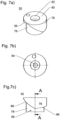
- Fig. 7 a) to 7 e) show the worm wheel 50 in different representations.
- Fig. 7 a shows the worm wheel 50 in a perspective view.
- the worm wheel 50 comprises a cylindrical body in the outer wall 76 of which a portion 78 is exposed to form the screw thread 56 .
- a receptacle 82 such as a blind hole, is formed in an end face 80 of the cylindrical body, in which a bearing (not shown) for the end bearing of the worm wheel 50 can be introduced.
- Fig. 7 b shows a plan view of the worm wheel 50, which has an opening 84 in the axial direction for receiving an axle for driving the worm 50.
- the figures 7 c) and 7d) 12 show side views of the worm wheel 50 in different rotational positions.
- the screw thread 56 has different pitches in the circumferential direction.
- a first flight section 86 which is designed to compress the pump 38, has a slight pitch and has a circumferential extent of approximately 270°.
- a second screw thread section 88 has a greater pitch and is used for the guided and controlled return of the pump 38 as a stop for the slide 58 in order to avoid a jerky expansion of the pump 38, which would lead to shocks.
- Fig. 7e shows a sectional view of the worm 50 with opening 84 and receptacle 82 for a front bearing.
- the latter has a transmitter 90, such as a magnet, on the front side, which interacts with a sensor 92, which is arranged opposite the magnet 90 in a housing wall 94.
- the sensor 92 is part of a control unit 96, which is in the form of z. B. a board on the housing wall 94 in the front area of the housing 12 is arranged.
- the control unit 96 can also include a control element 98, such as a capacitive sensor, for actuating the motor when a hand is approached.
- the electric motor 54 is activated so that the worm wheel 50 is rotated.
- the slide 58 is moved linearly in the direction of the longitudinal axis 62, as a result of which the pump 38 is compressed for dispensing the fluid in portions.
- the slide 58 is returned in a controlled manner by means of the second helical section with a negative pitch.
- the worm wheel 50 has a single thread 56 by which the pump 38 is actuated, i.e. the adjustment of the element for conveying the fluid and returning it to the starting position of the element in the exemplary embodiment of the bellows, results in a simple construction and thus a smaller maintenance needs. A susceptibility to failure is minimized.
Landscapes
- Health & Medical Sciences (AREA)
- Public Health (AREA)
- Reciprocating Pumps (AREA)
- Nozzles (AREA)
Claims (9)
- Distributeur de fluide (10), en particulier distributeur de savon, comprenant un réservoir de fluide (22), une pompe (38) couplée à un moteur électrique (108) via un élément de couplage (94) et pouvant être commandée pour distribuer du fluide par dose, sachant que la pompe est raccordée côté entrée au réservoir de fluide et côté sortie à une ouverture permettant de distribuer le fluide, ainsi qu'une unité de commande avec un élément de commande pour commander le moteur, sachant que l'élément de couplage (94), au moins pendant la distribution du fluide, est en liaison active avec au moins un pas de vis (56) d'une roue à vis (50) pouvant être entraînée au moyen du moteur (54), sachant qu'une rotation de la roue à vis (50) génère un déplacement axial de l'élément de couplage (58) et par conséquent un actionnement de la pompe (38) pour une distribution du fluide par dose,
caractérisé en ce
que la roue à vis (50) présente un pas de vis unique (56). - Distributeur de fluide selon la revendication 1,
caractérisé en ce
que l'unique pas de vis (56) présente une première section de pas de vis (86) avec un pas positif pour appliquer une force à l'élément de couplage (58) à partir d'une position initiale pour distribuer le fluide. - Distributeur de fluide selon au moins la revendication 2,
caractérisé en ce
que la première section de pas de vis (86) avec le pas positif se transforme en continu en une deuxième section de pas de vis (88) avec un pas négatif, contre laquelle l'élément de couplage (58) s'applique dans sa position initiale lors du retour de la pompe (38) ou de son élément permettant la distribution du fluide. - Distributeur de fluide selon au moins la revendication 3,
caractérisé en ce
que la première section de pas de vis (86) avec le pas positif se transforme de manière discontinue en une arête, de sorte que l'élément de couplage (58) n'est pas en liaison active avec le pas de vis (56) lors du retour de la pompe (38) ou de son élément permettant le refoulement du fluide. - Distributeur de fluide selon au moins l'une des revendications précédentes,
caractérisé en ce
que l'élément de couplage (58) est conçu sous la forme d'un poussoir qui est disposé de manière à pouvoir se déplacer dans la direction axiale d'une extension longitudinale d'un soufflet ou d'un piston de la pompe (38), sachant que de préférence un élément, tel qu'une broche (62), part du poussoir (58), ledit élément interagissant par engrènement avec au moins un pas de vis (56) de la roue à vis (50). - Distributeur de fluide selon la revendication 5,
caractérisé en ce
qu'un palier (44), tel qu'un roulement à billes, est disposé sur l'élément, tel qu'une broche (62), qui s'applique contre le pas de vis (56) de la roue à vis (50) et roule sur celui-ci. - Distributeur de fluide selon au moins l'une des revendications précédentes,
caractérisé en ce
que l'élément de couplage (58) est couplé à un soufflet ou un piston de la pompe (38) et/ou que l'élément de couplage (58), le soufflet et/ou le piston de la pompe (38) sont soumis à une précontrainte par ressort. - Distributeur de fluide selon au moins l'une des revendications précédentes,
caractérisé en ce
que le distributeur de fluide (10) présente un dispositif (90, 92) de détection d'un rapprochement de l'élément de couplage (58) dans sa position initiale et/ou de commande du moteur (54). - Distributeur de fluide selon au moins la revendication 8,
caractérisé en ce
que le dispositif présente un transmetteur (90), tel qu'un aimant, sur l'élément de couplage (58), et un capteur (92), tel qu'un capteur magnétique, sur une paroi du boîtier (94) ou inversement.
Priority Applications (2)
| Application Number | Priority Date | Filing Date | Title |
|---|---|---|---|
| SI201930591T SI3866655T1 (sl) | 2018-10-18 | 2019-10-15 | Razdeljevalnik tekočine |
| HRP20230843TT HRP20230843T1 (hr) | 2018-10-18 | 2019-10-15 | Razdjeljivač fluida |
Applications Claiming Priority (2)
| Application Number | Priority Date | Filing Date | Title |
|---|---|---|---|
| DE102018125905.0A DE102018125905B3 (de) | 2018-10-18 | 2018-10-18 | Fluidspender |
| PCT/EP2019/077923 WO2020078981A1 (fr) | 2018-10-18 | 2019-10-15 | Distributeur de fluide |
Publications (2)
| Publication Number | Publication Date |
|---|---|
| EP3866655A1 EP3866655A1 (fr) | 2021-08-25 |
| EP3866655B1 true EP3866655B1 (fr) | 2023-05-17 |
Family
ID=68318848
Family Applications (1)
| Application Number | Title | Priority Date | Filing Date |
|---|---|---|---|
| EP19791188.6A Active EP3866655B1 (fr) | 2018-10-18 | 2019-10-15 | Distributeur de fluide |
Country Status (10)
| Country | Link |
|---|---|
| EP (1) | EP3866655B1 (fr) |
| DE (1) | DE102018125905B3 (fr) |
| DK (1) | DK3866655T3 (fr) |
| ES (1) | ES2953023T3 (fr) |
| FI (1) | FI3866655T3 (fr) |
| HR (1) | HRP20230843T1 (fr) |
| HU (1) | HUE062557T2 (fr) |
| PL (1) | PL3866655T3 (fr) |
| SI (1) | SI3866655T1 (fr) |
| WO (1) | WO2020078981A1 (fr) |
Family Cites Families (9)
| Publication number | Priority date | Publication date | Assignee | Title |
|---|---|---|---|---|
| US5492247A (en) * | 1994-06-02 | 1996-02-20 | Shu; Aling | Automatic soap dispenser |
| US6209752B1 (en) * | 1999-03-10 | 2001-04-03 | Kimberly-Clark Worldwide, Inc. | Automatic soap dispenser |
| US7597122B1 (en) * | 2001-07-26 | 2009-10-06 | Smith Judson L | Apparatus and method to monitor the usage of a network system of personal hand sanitizing dispensers |
| US6607103B2 (en) * | 2001-10-12 | 2003-08-19 | Gerenraich Family Trust | Touch free dispenser |
| MXPA04003434A (es) * | 2001-10-15 | 2004-07-08 | Gerenraich Family Trust | Dispensador libre de contacto. |
| DE20320332U1 (de) | 2003-04-01 | 2004-06-09 | Blatz, Wilhelm | Elektronischer Fluidspender |
| US9655478B2 (en) * | 2013-01-17 | 2017-05-23 | Dispensing Dynamics International | Dispenser apparatus for dispensing liquid soap, lotion or other liquid |
| US8827119B2 (en) * | 2013-01-23 | 2014-09-09 | Gojo Industries, Inc. | Pull pumps, refill units and dispensers for pull pumps |
| US10189038B2 (en) * | 2013-12-20 | 2019-01-29 | Toaster Labs, Inc. | Inductively heatable fluid reservoir for various fluid types |
-
2018
- 2018-10-18 DE DE102018125905.0A patent/DE102018125905B3/de active Active
-
2019
- 2019-10-15 DK DK19791188.6T patent/DK3866655T3/da active
- 2019-10-15 PL PL19791188.6T patent/PL3866655T3/pl unknown
- 2019-10-15 ES ES19791188T patent/ES2953023T3/es active Active
- 2019-10-15 WO PCT/EP2019/077923 patent/WO2020078981A1/fr not_active Ceased
- 2019-10-15 HU HUE19791188A patent/HUE062557T2/hu unknown
- 2019-10-15 SI SI201930591T patent/SI3866655T1/sl unknown
- 2019-10-15 EP EP19791188.6A patent/EP3866655B1/fr active Active
- 2019-10-15 FI FIEP19791188.6T patent/FI3866655T3/fi active
- 2019-10-15 HR HRP20230843TT patent/HRP20230843T1/hr unknown
Non-Patent Citations (1)
| Title |
|---|
| ANONYMOUS: "Worm drive - Wikipedia", 18 February 2010 (2010-02-18), XP055678701, Retrieved from the Internet <URL:https://en.wikipedia.org/wiki/Worm_drive> [retrieved on 20200323] * |
Also Published As
| Publication number | Publication date |
|---|---|
| DK3866655T3 (da) | 2023-08-21 |
| FI3866655T3 (fi) | 2023-08-08 |
| HUE062557T2 (hu) | 2023-11-28 |
| DE102018125905B3 (de) | 2020-02-20 |
| HRP20230843T1 (hr) | 2023-11-10 |
| EP3866655A1 (fr) | 2021-08-25 |
| PL3866655T3 (pl) | 2023-10-02 |
| ES2953023T3 (es) | 2023-11-07 |
| WO2020078981A1 (fr) | 2020-04-23 |
| SI3866655T1 (sl) | 2023-10-30 |
Similar Documents
| Publication | Publication Date | Title |
|---|---|---|
| EP1523637B1 (fr) | Dispositif de dosage pour lubrifiant | |
| EP2150299B1 (fr) | Dispositif d'injection | |
| DE1566585B1 (de) | Einspritzgeraet fuer Roentgenkontrastmittel | |
| DE8218891U1 (de) | Medizinisches infusionsgeraet | |
| DE2731102C3 (de) | Pipettiergerät | |
| EP1213529A1 (fr) | Distributeur de graisse | |
| DE69303516T2 (de) | Lineare Peristaltikpumpe | |
| EP0399947B1 (fr) | Dispositif de mesure de volume et de dosage | |
| DE102011054404B4 (de) | Spender | |
| EP1752172A1 (fr) | Méchanisme de entraînement pour une pompe à infusion | |
| WO1997017096A1 (fr) | Dispositif d'injection | |
| EP3866655B1 (fr) | Distributeur de fluide | |
| DE4214827A1 (de) | Vorrichtung zum dosierten Zuführen von flüssigen oder viskosen Substanzen an eine Verbrauchsstelle | |
| EP3174639B1 (fr) | Distributeur sans contact pour distribuer des milieux liquides | |
| EP0365753B1 (fr) | Mécanisme de pulvérisation pour flacons pulvérisateur | |
| WO2011091544A1 (fr) | Dispositif d'entraînement et pompe à piston dotée d'un dispositif d'entraînement | |
| EP0886127B1 (fr) | Dispositif de dosage pour produits visqueux | |
| DE20320332U1 (de) | Elektronischer Fluidspender | |
| DE102022116513B3 (de) | Dosiersystem | |
| DE3836291A1 (de) | Spraymechanismus fuer sprayflaschen | |
| DE3411204C2 (de) | Dosiervorrichtung für die Abgabe einer genau vorgegebenen Flüssigkeitsmenge | |
| DE3517927C1 (de) | Infusionspumpe | |
| DE3144824A1 (de) | Spritzenpumpe | |
| DE1566585C (de) | Einspritzgerat fur Rontgenkontrast mittel | |
| CH699581A2 (de) | Vorrichtung mit einem Griff. |
Legal Events
| Date | Code | Title | Description |
|---|---|---|---|
| REG | Reference to a national code |
Ref country code: HR Ref legal event code: TUEP Ref document number: P20230843T Country of ref document: HR |
|
| STAA | Information on the status of an ep patent application or granted ep patent |
Free format text: STATUS: UNKNOWN |
|
| STAA | Information on the status of an ep patent application or granted ep patent |
Free format text: STATUS: THE INTERNATIONAL PUBLICATION HAS BEEN MADE |
|
| PUAI | Public reference made under article 153(3) epc to a published international application that has entered the european phase |
Free format text: ORIGINAL CODE: 0009012 |
|
| STAA | Information on the status of an ep patent application or granted ep patent |
Free format text: STATUS: REQUEST FOR EXAMINATION WAS MADE |
|
| 17P | Request for examination filed |
Effective date: 20210506 |
|
| AK | Designated contracting states |
Kind code of ref document: A1 Designated state(s): AL AT BE BG CH CY CZ DE DK EE ES FI FR GB GR HR HU IE IS IT LI LT LU LV MC MK MT NL NO PL PT RO RS SE SI SK SM TR |
|
| RIN1 | Information on inventor provided before grant (corrected) |
Inventor name: BILETSKYI, ROMAN Inventor name: GOTTSCHALK, ERIC |
|
| DAV | Request for validation of the european patent (deleted) | ||
| DAX | Request for extension of the european patent (deleted) | ||
| GRAP | Despatch of communication of intention to grant a patent |
Free format text: ORIGINAL CODE: EPIDOSNIGR1 |
|
| STAA | Information on the status of an ep patent application or granted ep patent |
Free format text: STATUS: GRANT OF PATENT IS INTENDED |
|
| INTG | Intention to grant announced |
Effective date: 20220627 |
|
| GRAS | Grant fee paid |
Free format text: ORIGINAL CODE: EPIDOSNIGR3 |
|
| GRAJ | Information related to disapproval of communication of intention to grant by the applicant or resumption of examination proceedings by the epo deleted |
Free format text: ORIGINAL CODE: EPIDOSDIGR1 |
|
| GRAL | Information related to payment of fee for publishing/printing deleted |
Free format text: ORIGINAL CODE: EPIDOSDIGR3 |
|
| STAA | Information on the status of an ep patent application or granted ep patent |
Free format text: STATUS: REQUEST FOR EXAMINATION WAS MADE |
|
| GRAP | Despatch of communication of intention to grant a patent |
Free format text: ORIGINAL CODE: EPIDOSNIGR1 |
|
| STAA | Information on the status of an ep patent application or granted ep patent |
Free format text: STATUS: GRANT OF PATENT IS INTENDED |
|
| INTC | Intention to grant announced (deleted) | ||
| RAP3 | Party data changed (applicant data changed or rights of an application transferred) |
Owner name: ILLE PAPIER-SERVICE GMBH |
|
| INTG | Intention to grant announced |
Effective date: 20221129 |
|
| GRAA | (expected) grant |
Free format text: ORIGINAL CODE: 0009210 |
|
| STAA | Information on the status of an ep patent application or granted ep patent |
Free format text: STATUS: THE PATENT HAS BEEN GRANTED |
|
| AK | Designated contracting states |
Kind code of ref document: B1 Designated state(s): AL AT BE BG CH CY CZ DE DK EE ES FI FR GB GR HR HU IE IS IT LI LT LU LV MC MK MT NL NO PL PT RO RS SE SI SK SM TR |
|
| REG | Reference to a national code |
Ref country code: GB Ref legal event code: FG4D Free format text: NOT ENGLISH |
|
| REG | Reference to a national code |
Ref country code: CH Ref legal event code: EP |
|
| REG | Reference to a national code |
Ref country code: DE Ref legal event code: R096 Ref document number: 502019007743 Country of ref document: DE |
|
| REG | Reference to a national code |
Ref country code: IE Ref legal event code: FG4D Free format text: LANGUAGE OF EP DOCUMENT: GERMAN |
|
| REG | Reference to a national code |
Ref country code: AT Ref legal event code: REF Ref document number: 1568099 Country of ref document: AT Kind code of ref document: T Effective date: 20230615 |
|
| P01 | Opt-out of the competence of the unified patent court (upc) registered |
Effective date: 20230527 |
|
| REG | Reference to a national code |
Ref country code: FI Ref legal event code: FGE |
|
| REG | Reference to a national code |
Ref country code: RO Ref legal event code: EPE |
|
| REG | Reference to a national code |
Ref country code: DK Ref legal event code: T3 Effective date: 20230814 |
|
| REG | Reference to a national code |
Ref country code: NL Ref legal event code: FP |
|
| REG | Reference to a national code |
Ref country code: SE Ref legal event code: TRGR |
|
| REG | Reference to a national code |
Ref country code: LT Ref legal event code: MG9D |
|
| REG | Reference to a national code |
Ref country code: SK Ref legal event code: T3 Ref document number: E 42042 Country of ref document: SK |
|
| REG | Reference to a national code |
Ref country code: HR Ref legal event code: ODRP Ref document number: P20230843T Country of ref document: HR Payment date: 20231005 Year of fee payment: 5 |
|
| PG25 | Lapsed in a contracting state [announced via postgrant information from national office to epo] |
Ref country code: PT Free format text: LAPSE BECAUSE OF FAILURE TO SUBMIT A TRANSLATION OF THE DESCRIPTION OR TO PAY THE FEE WITHIN THE PRESCRIBED TIME-LIMIT Effective date: 20230918 Ref country code: NO Free format text: LAPSE BECAUSE OF FAILURE TO SUBMIT A TRANSLATION OF THE DESCRIPTION OR TO PAY THE FEE WITHIN THE PRESCRIBED TIME-LIMIT Effective date: 20230817 |
|
| REG | Reference to a national code |
Ref country code: HR Ref legal event code: T1PR Ref document number: P20230843 Country of ref document: HR |
|
| REG | Reference to a national code |
Ref country code: HU Ref legal event code: AG4A Ref document number: E062557 Country of ref document: HU |
|
| PG25 | Lapsed in a contracting state [announced via postgrant information from national office to epo] |
Ref country code: RS Free format text: LAPSE BECAUSE OF FAILURE TO SUBMIT A TRANSLATION OF THE DESCRIPTION OR TO PAY THE FEE WITHIN THE PRESCRIBED TIME-LIMIT Effective date: 20230517 Ref country code: LV Free format text: LAPSE BECAUSE OF FAILURE TO SUBMIT A TRANSLATION OF THE DESCRIPTION OR TO PAY THE FEE WITHIN THE PRESCRIBED TIME-LIMIT Effective date: 20230517 Ref country code: LT Free format text: LAPSE BECAUSE OF FAILURE TO SUBMIT A TRANSLATION OF THE DESCRIPTION OR TO PAY THE FEE WITHIN THE PRESCRIBED TIME-LIMIT Effective date: 20230517 Ref country code: IS Free format text: LAPSE BECAUSE OF FAILURE TO SUBMIT A TRANSLATION OF THE DESCRIPTION OR TO PAY THE FEE WITHIN THE PRESCRIBED TIME-LIMIT Effective date: 20230917 Ref country code: GR Free format text: LAPSE BECAUSE OF FAILURE TO SUBMIT A TRANSLATION OF THE DESCRIPTION OR TO PAY THE FEE WITHIN THE PRESCRIBED TIME-LIMIT Effective date: 20230818 |
|
| PG25 | Lapsed in a contracting state [announced via postgrant information from national office to epo] |
Ref country code: SM Free format text: LAPSE BECAUSE OF FAILURE TO SUBMIT A TRANSLATION OF THE DESCRIPTION OR TO PAY THE FEE WITHIN THE PRESCRIBED TIME-LIMIT Effective date: 20230517 Ref country code: EE Free format text: LAPSE BECAUSE OF FAILURE TO SUBMIT A TRANSLATION OF THE DESCRIPTION OR TO PAY THE FEE WITHIN THE PRESCRIBED TIME-LIMIT Effective date: 20230517 |
|
| REG | Reference to a national code |
Ref country code: DE Ref legal event code: R097 Ref document number: 502019007743 Country of ref document: DE |
|
| PLBE | No opposition filed within time limit |
Free format text: ORIGINAL CODE: 0009261 |
|
| STAA | Information on the status of an ep patent application or granted ep patent |
Free format text: STATUS: NO OPPOSITION FILED WITHIN TIME LIMIT |
|
| 26N | No opposition filed |
Effective date: 20240220 |
|
| PG25 | Lapsed in a contracting state [announced via postgrant information from national office to epo] |
Ref country code: MC Free format text: LAPSE BECAUSE OF FAILURE TO SUBMIT A TRANSLATION OF THE DESCRIPTION OR TO PAY THE FEE WITHIN THE PRESCRIBED TIME-LIMIT Effective date: 20230517 |
|
| PG25 | Lapsed in a contracting state [announced via postgrant information from national office to epo] |
Ref country code: FR Free format text: LAPSE BECAUSE OF NON-PAYMENT OF DUE FEES Effective date: 20231031 |
|
| PG25 | Lapsed in a contracting state [announced via postgrant information from national office to epo] |
Ref country code: BG Free format text: LAPSE BECAUSE OF FAILURE TO SUBMIT A TRANSLATION OF THE DESCRIPTION OR TO PAY THE FEE WITHIN THE PRESCRIBED TIME-LIMIT Effective date: 20230517 |
|
| REG | Reference to a national code |
Ref country code: HR Ref legal event code: ODRP Ref document number: P20230843 Country of ref document: HR Payment date: 20241003 Year of fee payment: 6 |
|
| PG25 | Lapsed in a contracting state [announced via postgrant information from national office to epo] |
Ref country code: BG Free format text: LAPSE BECAUSE OF FAILURE TO SUBMIT A TRANSLATION OF THE DESCRIPTION OR TO PAY THE FEE WITHIN THE PRESCRIBED TIME-LIMIT Effective date: 20230517 |
|
| PGFP | Annual fee paid to national office [announced via postgrant information from national office to epo] |
Ref country code: FI Payment date: 20241025 Year of fee payment: 6 |
|
| PG25 | Lapsed in a contracting state [announced via postgrant information from national office to epo] |
Ref country code: CY Free format text: LAPSE BECAUSE OF FAILURE TO SUBMIT A TRANSLATION OF THE DESCRIPTION OR TO PAY THE FEE WITHIN THE PRESCRIBED TIME-LIMIT; INVALID AB INITIO Effective date: 20191015 |
|
| PGFP | Annual fee paid to national office [announced via postgrant information from national office to epo] |
Ref country code: PL Payment date: 20250918 Year of fee payment: 7 |
|
| PGFP | Annual fee paid to national office [announced via postgrant information from national office to epo] |
Ref country code: SI Payment date: 20251002 Year of fee payment: 7 |
|
| REG | Reference to a national code |
Ref country code: CH Ref legal event code: U11 Free format text: ST27 STATUS EVENT CODE: U-0-0-U10-U11 (AS PROVIDED BY THE NATIONAL OFFICE) Effective date: 20251101 |
|
| REG | Reference to a national code |
Ref country code: HR Ref legal event code: ODRP Ref document number: P20230843 Country of ref document: HR Payment date: 20251002 Year of fee payment: 7 |
|
| PGFP | Annual fee paid to national office [announced via postgrant information from national office to epo] |
Ref country code: HU Payment date: 20251027 Year of fee payment: 7 |
|
| PGFP | Annual fee paid to national office [announced via postgrant information from national office to epo] |
Ref country code: LU Payment date: 20251022 Year of fee payment: 7 Ref country code: NL Payment date: 20251021 Year of fee payment: 7 |
|
| PG25 | Lapsed in a contracting state [announced via postgrant information from national office to epo] |
Ref country code: TR Free format text: LAPSE BECAUSE OF FAILURE TO SUBMIT A TRANSLATION OF THE DESCRIPTION OR TO PAY THE FEE WITHIN THE PRESCRIBED TIME-LIMIT Effective date: 20230517 |
|
| PGFP | Annual fee paid to national office [announced via postgrant information from national office to epo] |
Ref country code: DE Payment date: 20251009 Year of fee payment: 7 |
|
| PGFP | Annual fee paid to national office [announced via postgrant information from national office to epo] |
Ref country code: GB Payment date: 20251022 Year of fee payment: 7 |
|
| PGFP | Annual fee paid to national office [announced via postgrant information from national office to epo] |
Ref country code: AT Payment date: 20251022 Year of fee payment: 7 |
|
| PGFP | Annual fee paid to national office [announced via postgrant information from national office to epo] |
Ref country code: DK Payment date: 20251027 Year of fee payment: 7 Ref country code: IT Payment date: 20251024 Year of fee payment: 7 |
|
| PGFP | Annual fee paid to national office [announced via postgrant information from national office to epo] |
Ref country code: HR Payment date: 20251002 Year of fee payment: 7 |
|
| PGFP | Annual fee paid to national office [announced via postgrant information from national office to epo] |
Ref country code: BE Payment date: 20251021 Year of fee payment: 7 |
|
| PGFP | Annual fee paid to national office [announced via postgrant information from national office to epo] |
Ref country code: CH Payment date: 20251101 Year of fee payment: 7 Ref country code: SE Payment date: 20251021 Year of fee payment: 7 |
|
| PGFP | Annual fee paid to national office [announced via postgrant information from national office to epo] |
Ref country code: IE Payment date: 20251024 Year of fee payment: 7 Ref country code: CZ Payment date: 20251009 Year of fee payment: 7 |
|
| PGFP | Annual fee paid to national office [announced via postgrant information from national office to epo] |
Ref country code: SK Payment date: 20251008 Year of fee payment: 7 Ref country code: RO Payment date: 20251003 Year of fee payment: 7 |
|
| PGFP | Annual fee paid to national office [announced via postgrant information from national office to epo] |
Ref country code: ES Payment date: 20251216 Year of fee payment: 7 |