EP3867155B1 - Dispositif d'amortissement de fluide dans un réservoir, en particulier d'un engin spatial - Google Patents
Dispositif d'amortissement de fluide dans un réservoir, en particulier d'un engin spatial Download PDFInfo
- Publication number
- EP3867155B1 EP3867155B1 EP19842589.4A EP19842589A EP3867155B1 EP 3867155 B1 EP3867155 B1 EP 3867155B1 EP 19842589 A EP19842589 A EP 19842589A EP 3867155 B1 EP3867155 B1 EP 3867155B1
- Authority
- EP
- European Patent Office
- Prior art keywords
- rods
- ring
- tank
- spacecraft
- fluid
- Prior art date
- Legal status (The legal status is an assumption and is not a legal conclusion. Google has not performed a legal analysis and makes no representation as to the accuracy of the status listed.)
- Active
Links
Images


Classifications
-
- B—PERFORMING OPERATIONS; TRANSPORTING
- B64—AIRCRAFT; AVIATION; COSMONAUTICS
- B64G—COSMONAUTICS; VEHICLES OR EQUIPMENT THEREFOR
- B64G1/00—Cosmonautic vehicles
- B64G1/22—Parts of, or equipment specially adapted for fitting in or to, cosmonautic vehicles
- B64G1/40—Arrangements or adaptations of propulsion systems
- B64G1/402—Propellant tanks; Feeding propellants
- B64G1/4021—Tank construction; Details thereof
-
- F—MECHANICAL ENGINEERING; LIGHTING; HEATING; WEAPONS; BLASTING
- F17—STORING OR DISTRIBUTING GASES OR LIQUIDS
- F17C—VESSELS FOR CONTAINING OR STORING COMPRESSED, LIQUEFIED OR SOLIDIFIED GASES; FIXED-CAPACITY GAS-HOLDERS; FILLING VESSELS WITH, OR DISCHARGING FROM VESSELS, COMPRESSED, LIQUEFIED, OR SOLIDIFIED GASES
- F17C13/00—Details of vessels or of the filling or discharging of vessels
- F17C13/008—Details of vessels or of the filling or discharging of vessels for use under microgravity conditions
-
- B—PERFORMING OPERATIONS; TRANSPORTING
- B60—VEHICLES IN GENERAL
- B60K—ARRANGEMENT OR MOUNTING OF PROPULSION UNITS OR OF TRANSMISSIONS IN VEHICLES; ARRANGEMENT OR MOUNTING OF PLURAL DIVERSE PRIME-MOVERS IN VEHICLES; AUXILIARY DRIVES FOR VEHICLES; INSTRUMENTATION OR DASHBOARDS FOR VEHICLES; ARRANGEMENTS IN CONNECTION WITH COOLING, AIR INTAKE, GAS EXHAUST OR FUEL SUPPLY OF PROPULSION UNITS IN VEHICLES
- B60K15/00—Arrangement in connection with fuel supply of combustion engines or other fuel consuming energy converters, e.g. fuel cells; Mounting or construction of fuel tanks
- B60K15/03—Fuel tanks
- B60K15/077—Fuel tanks with means modifying or controlling distribution or motion of fuel, e.g. to prevent noise, surge, splash or fuel starvation
-
- F—MECHANICAL ENGINEERING; LIGHTING; HEATING; WEAPONS; BLASTING
- F02—COMBUSTION ENGINES; HOT-GAS OR COMBUSTION-PRODUCT ENGINE PLANTS
- F02K—JET-PROPULSION PLANTS
- F02K9/00—Rocket-engine plants, i.e. plants carrying both fuel and oxidant therefor; Control thereof
- F02K9/42—Rocket-engine plants, i.e. plants carrying both fuel and oxidant therefor; Control thereof using liquid or gaseous propellants
- F02K9/60—Constructional parts; Details not otherwise provided for
- F02K9/605—Reservoirs
-
- B—PERFORMING OPERATIONS; TRANSPORTING
- B60—VEHICLES IN GENERAL
- B60K—ARRANGEMENT OR MOUNTING OF PROPULSION UNITS OR OF TRANSMISSIONS IN VEHICLES; ARRANGEMENT OR MOUNTING OF PLURAL DIVERSE PRIME-MOVERS IN VEHICLES; AUXILIARY DRIVES FOR VEHICLES; INSTRUMENTATION OR DASHBOARDS FOR VEHICLES; ARRANGEMENTS IN CONNECTION WITH COOLING, AIR INTAKE, GAS EXHAUST OR FUEL SUPPLY OF PROPULSION UNITS IN VEHICLES
- B60K15/00—Arrangement in connection with fuel supply of combustion engines or other fuel consuming energy converters, e.g. fuel cells; Mounting or construction of fuel tanks
- B60K15/03—Fuel tanks
- B60K15/077—Fuel tanks with means modifying or controlling distribution or motion of fuel, e.g. to prevent noise, surge, splash or fuel starvation
- B60K2015/0775—Fuel tanks with means modifying or controlling distribution or motion of fuel, e.g. to prevent noise, surge, splash or fuel starvation for reducing movement or slash noise of fuel
-
- B—PERFORMING OPERATIONS; TRANSPORTING
- B60—VEHICLES IN GENERAL
- B60Y—INDEXING SCHEME RELATING TO ASPECTS CROSS-CUTTING VEHICLE TECHNOLOGY
- B60Y2200/00—Type of vehicle
- B60Y2200/50—Aeroplanes, Helicopters
-
- F—MECHANICAL ENGINEERING; LIGHTING; HEATING; WEAPONS; BLASTING
- F05—INDEXING SCHEMES RELATING TO ENGINES OR PUMPS IN VARIOUS SUBCLASSES OF CLASSES F01-F04
- F05D—INDEXING SCHEME FOR ASPECTS RELATING TO NON-POSITIVE-DISPLACEMENT MACHINES OR ENGINES, GAS-TURBINES OR JET-PROPULSION PLANTS
- F05D2250/00—Geometry
- F05D2250/20—Three-dimensional
- F05D2250/23—Three-dimensional prismatic
- F05D2250/231—Three-dimensional prismatic cylindrical
-
- F—MECHANICAL ENGINEERING; LIGHTING; HEATING; WEAPONS; BLASTING
- F05—INDEXING SCHEMES RELATING TO ENGINES OR PUMPS IN VARIOUS SUBCLASSES OF CLASSES F01-F04
- F05D—INDEXING SCHEME FOR ASPECTS RELATING TO NON-POSITIVE-DISPLACEMENT MACHINES OR ENGINES, GAS-TURBINES OR JET-PROPULSION PLANTS
- F05D2250/00—Geometry
- F05D2250/20—Three-dimensional
- F05D2250/23—Three-dimensional prismatic
- F05D2250/232—Three-dimensional prismatic conical
-
- F—MECHANICAL ENGINEERING; LIGHTING; HEATING; WEAPONS; BLASTING
- F05—INDEXING SCHEMES RELATING TO ENGINES OR PUMPS IN VARIOUS SUBCLASSES OF CLASSES F01-F04
- F05D—INDEXING SCHEME FOR ASPECTS RELATING TO NON-POSITIVE-DISPLACEMENT MACHINES OR ENGINES, GAS-TURBINES OR JET-PROPULSION PLANTS
- F05D2300/00—Materials; Properties thereof
- F05D2300/50—Intrinsic material properties or characteristics
- F05D2300/514—Porosity
-
- F—MECHANICAL ENGINEERING; LIGHTING; HEATING; WEAPONS; BLASTING
- F17—STORING OR DISTRIBUTING GASES OR LIQUIDS
- F17C—VESSELS FOR CONTAINING OR STORING COMPRESSED, LIQUEFIED OR SOLIDIFIED GASES; FIXED-CAPACITY GAS-HOLDERS; FILLING VESSELS WITH, OR DISCHARGING FROM VESSELS, COMPRESSED, LIQUEFIED, OR SOLIDIFIED GASES
- F17C2201/00—Vessel construction, in particular geometry, arrangement or size
- F17C2201/01—Shape
- F17C2201/0128—Shape spherical or elliptical
-
- F—MECHANICAL ENGINEERING; LIGHTING; HEATING; WEAPONS; BLASTING
- F17—STORING OR DISTRIBUTING GASES OR LIQUIDS
- F17C—VESSELS FOR CONTAINING OR STORING COMPRESSED, LIQUEFIED OR SOLIDIFIED GASES; FIXED-CAPACITY GAS-HOLDERS; FILLING VESSELS WITH, OR DISCHARGING FROM VESSELS, COMPRESSED, LIQUEFIED, OR SOLIDIFIED GASES
- F17C2201/00—Vessel construction, in particular geometry, arrangement or size
- F17C2201/05—Size
- F17C2201/054—Size medium (>1 m3)
-
- F—MECHANICAL ENGINEERING; LIGHTING; HEATING; WEAPONS; BLASTING
- F17—STORING OR DISTRIBUTING GASES OR LIQUIDS
- F17C—VESSELS FOR CONTAINING OR STORING COMPRESSED, LIQUEFIED OR SOLIDIFIED GASES; FIXED-CAPACITY GAS-HOLDERS; FILLING VESSELS WITH, OR DISCHARGING FROM VESSELS, COMPRESSED, LIQUEFIED, OR SOLIDIFIED GASES
- F17C2201/00—Vessel construction, in particular geometry, arrangement or size
- F17C2201/05—Size
- F17C2201/056—Small (<1 m3)
-
- F—MECHANICAL ENGINEERING; LIGHTING; HEATING; WEAPONS; BLASTING
- F17—STORING OR DISTRIBUTING GASES OR LIQUIDS
- F17C—VESSELS FOR CONTAINING OR STORING COMPRESSED, LIQUEFIED OR SOLIDIFIED GASES; FIXED-CAPACITY GAS-HOLDERS; FILLING VESSELS WITH, OR DISCHARGING FROM VESSELS, COMPRESSED, LIQUEFIED, OR SOLIDIFIED GASES
- F17C2203/00—Vessel construction, in particular walls or details thereof
- F17C2203/01—Reinforcing or suspension means
- F17C2203/011—Reinforcing means
- F17C2203/012—Reinforcing means on or in the wall, e.g. ribs
-
- F—MECHANICAL ENGINEERING; LIGHTING; HEATING; WEAPONS; BLASTING
- F17—STORING OR DISTRIBUTING GASES OR LIQUIDS
- F17C—VESSELS FOR CONTAINING OR STORING COMPRESSED, LIQUEFIED OR SOLIDIFIED GASES; FIXED-CAPACITY GAS-HOLDERS; FILLING VESSELS WITH, OR DISCHARGING FROM VESSELS, COMPRESSED, LIQUEFIED, OR SOLIDIFIED GASES
- F17C2221/00—Handled fluid, in particular type of fluid
- F17C2221/01—Pure fluids
- F17C2221/012—Hydrogen
-
- F—MECHANICAL ENGINEERING; LIGHTING; HEATING; WEAPONS; BLASTING
- F17—STORING OR DISTRIBUTING GASES OR LIQUIDS
- F17C—VESSELS FOR CONTAINING OR STORING COMPRESSED, LIQUEFIED OR SOLIDIFIED GASES; FIXED-CAPACITY GAS-HOLDERS; FILLING VESSELS WITH, OR DISCHARGING FROM VESSELS, COMPRESSED, LIQUEFIED, OR SOLIDIFIED GASES
- F17C2223/00—Handled fluid before transfer, i.e. state of fluid when stored in the vessel or before transfer from the vessel
- F17C2223/01—Handled fluid before transfer, i.e. state of fluid when stored in the vessel or before transfer from the vessel characterised by the phase
- F17C2223/0146—Two-phase
- F17C2223/0153—Liquefied gas, e.g. LPG, GPL
- F17C2223/0161—Liquefied gas, e.g. LPG, GPL cryogenic, e.g. LNG, GNL, PLNG
-
- F—MECHANICAL ENGINEERING; LIGHTING; HEATING; WEAPONS; BLASTING
- F17—STORING OR DISTRIBUTING GASES OR LIQUIDS
- F17C—VESSELS FOR CONTAINING OR STORING COMPRESSED, LIQUEFIED OR SOLIDIFIED GASES; FIXED-CAPACITY GAS-HOLDERS; FILLING VESSELS WITH, OR DISCHARGING FROM VESSELS, COMPRESSED, LIQUEFIED, OR SOLIDIFIED GASES
- F17C2270/00—Applications
- F17C2270/01—Applications for fluid transport or storage
- F17C2270/0186—Applications for fluid transport or storage in the air or in space
- F17C2270/0194—Applications for fluid transport or storage in the air or in space for use under microgravity conditions, e.g. space
-
- Y—GENERAL TAGGING OF NEW TECHNOLOGICAL DEVELOPMENTS; GENERAL TAGGING OF CROSS-SECTIONAL TECHNOLOGIES SPANNING OVER SEVERAL SECTIONS OF THE IPC; TECHNICAL SUBJECTS COVERED BY FORMER USPC CROSS-REFERENCE ART COLLECTIONS [XRACs] AND DIGESTS
- Y02—TECHNOLOGIES OR APPLICATIONS FOR MITIGATION OR ADAPTATION AGAINST CLIMATE CHANGE
- Y02E—REDUCTION OF GREENHOUSE GAS [GHG] EMISSIONS, RELATED TO ENERGY GENERATION, TRANSMISSION OR DISTRIBUTION
- Y02E60/00—Enabling technologies; Technologies with a potential or indirect contribution to GHG emissions mitigation
- Y02E60/30—Hydrogen technology
- Y02E60/32—Hydrogen storage
Definitions
- the present invention relates to a device for damping a fluid contained in a reservoir.
- the present invention applies more particularly to a tank of a spacecraft.
- the flight of a spacecraft is made up of several phases, and ends with the release and deployment of a payload, in particular a satellite.
- the spacecraft generally comprises a plurality of successive stages. Each of these stages is provided with a rocket engine whose fuel is a propellant, that is to say a mixture of several propellants contained in several tanks arranged in each stage.
- the payload is usually in the last stage, called the upper stage of the spacecraft.
- the propellant used in the upper stage rocket motor comprises two cryogenic propellants, namely, liquid oxygen and liquid hydrogen. These two propellants cryogenics are kept in liquid state in two separate tanks arranged one above the other in the upper stage.
- the maneuvers of the spacecraft carried out under microgravity or low gravity can generate large movements of the liquid propellants in their tanks. These movements are more important for liquid hydrogen because it is a low density fluid.
- the tanks are cooled in order to maintain the propellants in their liquid phase, they may include zones whose temperature is higher than the critical vaporization temperature.
- a maneuver can cause an uncontrolled movement of the liquid hydrogen, such as sloshing movements.
- the liquid hydrogen then vaporizes on contact with these hotter zones.
- the products generated by the evaporation must then be evacuated from the tank. This reduction in the quantity of liquid hydrogen and therefore of propellant usable by the engine causes a loss of performance of the spacecraft. This loss of performance is manifested by a decrease in the quantity of liquid hydrogen which can reach several hundred kilograms.
- US5901557 discloses a spacecraft tank for storing pressurized cryogenic fluid under microgravity conditions.
- This tank is equipped with a system making it possible to extract from the tank only the liquid phase.
- This system comprises in particular a net arranged on a rigid frame comprising rods and rings so that a liquid can pass through it and reduce flow velocities.
- the object of the present invention is to remedy this drawback. To do this, it relates to a device for damping a fluid intended for a reservoir, in particular of a spacecraft.
- said device comprises a frame provided with at least one ring and a plurality of rods, each of said rods being fixed by a first end around said ring, said device comprising a net arranged on the plurality of rods and around the ring, the net comprising a mesh adapted to the viscosity of the fluid (to be damped) so as to damp movements of said fluid, said device further comprising a plurality of holding elements, each of the rods being arranged in a holding element by a second end opposite the first end.
- the device is configured to be able to be brought from a folded position to an unfolded position, the folded position corresponding to a position of the device in which the rods are arranged substantially parallel to each other and each of said rods forms a zero angle with a said longitudinal axis of said device, the unfolded position corresponding to a position of the device in which the rods are not mutually parallel and each of said rods forms an angle called deployment angle, said deployment angle being non-zero with the longitudinal axis.
- each of the holding elements is advantageously intended to be fixed to a part and to hold the device at least in the unfolded position.
- each of the holding elements comprises a locking system capable of locking the rods in a position corresponding to an unfolded position of the device.
- the value of the deployment angle between said rods and the longitudinal axis of the device depends on a porosity parameter of the mesh of the net.
- the porosity parameter is between 0.3 and 0.5.
- the ring is extensible in a so-called radial direction and configured to be able to be brought from a first state when the device is in the folded position to a second state when the device is in the unfolded position, the size of said ring in said first state being smaller than the size of said ring in said second state.
- the rods are distributed at regular angular intervals around the ring.
- the rods are made of an aluminum alloy.
- the use of aluminum rods makes it possible not to weigh down the device.
- the net is made of a polymer material.
- a polymer material makes it possible to obtain a net that is both flexible and light.
- the flexibility of the net makes it possible to dampen or stop the sloshing movements of the fluid, in particular without generating splashes.
- the present invention also relates to a tank, in particular for a spacecraft, comprising a fluid damping device such as that described above.
- the tank comprises a part arranged in a lower part, said part being configured to fix the device on said tank, said part being removable.
- the present invention further relates to a spacecraft comprising a tank such as that described above.
- the fluid damping device 1 (hereinafter "device 1"), represented schematically in a particular embodiment on the figure 1 and making it possible to illustrate the invention, is intended to make it possible to absorb a fluid in a tank 6.
- this fluid is liquid hydrogen present in the tank 6 of a spacecraft, the stage 11 of which comprising the tank 6 is represented very schematically on the figure 1 .
- this device 1 comprises, as shown in the figures 1 and 2 , a net 2, an armature 3 on which the net 2 is arranged and a plurality of holding elements 4.
- the elements of retaining 4 are able to maintain the net 2 and the reinforcement 3 in a fixed position on a part 5 of the tank 6, in particular during the flight of the spacecraft in the case of a tank 6 of a spacecraft.
- a reference mark R is used associated with the device 1 and defined along three orthogonal axes, namely a so-called longitudinal axis X which is oriented along the device 1, and two median axes Y and transverse Z which define a transverse plane YZ.
- the adjectives "upper” and “lower” with respect to the device 1 or to the reservoir 6 are defined according to the direction of an arrow F and the opposite direction of the arrow F respectively.
- the armature 3 comprises a plurality of rods 7 and at least one ring 8 arranged in the upper part of the device 1 (hereinafter “upper ring 8”).
- the upper ring 8 is of circular shape with center O belonging to the longitudinal axis X.
- the upper ring 8 is, moreover, arranged in a transverse plane YZ perpendicular to the longitudinal axis X
- the upper ring 8 is extensible in a radial direction perpendicular to the longitudinal axis X, as shown by arrows E.
- the upper ring 8 is a spring.
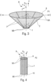
- the upper ring 8 can be brought from a first state, as shown in the figure 4 , to a second state, as shown in the picture 3 .
- the size of the upper ring 8 in the first state is smaller than the size of the upper ring 8 in the second state.
- the rods 7 are arranged around the upper ring 8.
- the armature 3 comprises eight rods 7.
- rods 7 are preferably made of aluminum.
- the use of aluminum rods 7 makes it possible not to weigh down the frame 3, which increases the performance of the spacecraft during its flight.
- each of the rods 7 of the frame 3 is provided with an end 9A by which it is fixed to the upper 8 ring.
- the ends 9A of two of the adjacent rods 7 around the upper ring 8 form, with the longitudinal axis X, an angle ⁇ .
- the rods 7 are arranged around the upper ring 8 at substantially equal angles ⁇ .
- each of the rods 7 is arranged in a radial plane defined by the longitudinal axis X and an arrow E.
- each of the rods 7 also includes an end 9B, opposite the end 9A.
- the rods 7 are arranged individually, by their ends 9B, in holding elements 4.
- the number of rods 7 is identical to the number of holding elements 4. Only one of the rods 7 is associated with only one of the holding elements 4 .
- the armature 3 further comprises a ring 10 arranged in a lower part of the armature 3.
- This so-called lower ring 10 is fixed to a zone of each of the rods 7 close to their second ends 9B.
- the lower ring 10 is rigid. Its size is the same as the size of the upper 8 ring when the upper 8 ring is in the first state, as shown in the figure 4 .
- the holding elements 4 are fixed to the part 5 of circular section.
- this part 5 is a removable element arranged in a lower part of the tank 6.
- the device 1 is then rigidly fixed to the tank 6.
- the holding elements 4 are arranged in a circle on the edge of the part 5.
- the circle is centered around the longitudinal axis X.
- the size of the circle formed by the holding elements 4 is substantially equal to the size of the upper ring 8 when it is in the first state.
- a particular rod 7 and a particular holding element 4, in which it is arranged form a pivot link (not shown).
- This pivot connection makes the rod 7 capable of performing rotational movements around a tangential axis perpendicular to the longitudinal axis X according to an angle ⁇ , as represented on the picture 3 .
- the first and second states of the upper ring 8 define, respectively, a minimum angle and an angle called the angle of deployment of each of the rods 7.
- the minimum angle is equal to zero and corresponds to a position rods 7 parallel to the longitudinal axis X, as shown in the figure 4 .
- each of the holding elements 4 comprises a locking system (not shown).
- This locking system makes it possible to block the rods 7 in a particular position associated with a particular angle ⁇ .
- a locking system is a lock or a clip.
- the net 2 is arranged along the rods 7 along the longitudinal axis X and around the upper ring 8.
- the net 2 is made of a polymer material. This type of material makes it possible to obtain a flexible and light net 2 .
- the mesh of the net 2 is adapted to the viscosity of the fluid which must be damped, in particular liquid hydrogen, present in the tank 6 in which the device 1 is arranged.
- the mesh size of net 2 is defined by at least one parameter representative of the porosity of net 2.
- the porosity parameter of net 2 is between 0.3 and 0.5.
- the device 1 can be brought from a folded position P2, represented on the figure 4 And 6 , to an unfolded position P1, represented by the picture 3 .
- the folded position P2 of the device 1 is associated with a configuration of the frame 3 such that the upper ring 8 is in the first state and the angle ⁇ between each of the rods 7 and the longitudinal axis X is equal to minimum angle (preferably zero).
- the rods 7 are substantially parallel to the longitudinal axis X.
- the unfolded position P1 of the device 1 is associated with another configuration of the armature 3.
- the ring 8 superior is in the second state.
- the angle ⁇ between each of the rods 7 and the longitudinal axis X corresponds to the deployment angle. The value of this deployment angle depends on the porosity parameter of the mesh of the net 2 and the viscosity of the fluid.
- the device 1 Before the flight of a spacecraft, the device 1 is fixed in the tank 6. To do this, the frame 3 and the net 2 are in a folded configuration, as represented by the figure 4 .
- the folded configuration of the frame 3 and of the net 2 corresponds to rods 7 substantially parallel to each other and with the longitudinal axis X and to an upper ring 8 in the first state.
- the holding elements 4 are then fixed on the part 5.
- This part 5, which is removable, can be the access door to the tank 6 which is arranged in the lower part of the tank 6.
- the holding elements 4 are arranged in a circle, as shown in the figure 5 .
- the rods 7, which form the frame 3 with the upper ring 8 and the lower ring 10, are arranged in the holding elements 4. As shown in the figure 6 , the device 1, which is in its folded position P2, is fixed to the tank access door 6.
- the device 1 is then introduced into the reservoir 6 through an orifice arranged in the lower part of the reservoir 6.
- This orifice corresponds to the location of the access door.
- the diameter of the orifice may be sixty-five centimeters.
- the device 1 is unfolded before the reservoir 6 is filled with the fluid and the angle of deployment is chosen according to the viscosity of the fluid and the porosity parameter of the mesh of the net 2, so as to limit the sloshing movements of the fluid. .
- the reservoir 6 is filled with fluid.
- a preferred application of the device 1 is the damping of sloshing movements of the liquid hydrogen present in the tank 6 of a spacecraft.
- the actual trajectory of the spacecraft, in particular a launch vehicle, is regularly adjusted during its flight. These adjustments are made by activating the rocket engines of the successive stages.
- the propellants of the upper stage such as liquid oxygen and liquid hydrogen then move in their respective tanks with each control of the attitude of the preceding stages. These adjustments take place when the launcher has left the Earth's atmosphere and is in a medium of low gravity or even microgravity.
- the propellants in particular liquid hydrogen, risk being vaporized in contact with hot zones of their tank 6, which correspondingly reduces the quantity of propellants usable by the spacecraft during his flight.
- the porosity parameter of the mesh of the net 2 is associated with the Carpenter-Keulegan number. This porosity parameter characterizes the effects of the viscosity of the liquid hydrogen and the degree of porosity of the mesh with respect in particular to the amplitude of the stress, for example the sloshing movements.
- the value of the porosity parameter is substantially equal to 0.4 so as to maximize a damping ratio when the Carpenter-Keulegan number is equal to 1.
- the sloshing movements of the liquid hydrogen are partially or totally reduced by the device 1, the effectiveness of which depends on the angle of deployment and the porosity parameter of the mesh of the net. For example, sloshing movements are reduced if the porosity parameter is equal to 0.4 for a deployment angle of 60 degrees.
- the dimensions of the device 1 are chosen so that it is effective according to the maximum of liquid hydrogen in the tank 6 when the adjustments of the trajectory under microgravity or weak gravity take place.
- the device 1 once unfolded, measures five meters in diameter and one hundred and fifty centimeters in height along the longitudinal axis X.
Landscapes
- Engineering & Computer Science (AREA)
- Combustion & Propulsion (AREA)
- Chemical & Material Sciences (AREA)
- Mechanical Engineering (AREA)
- General Engineering & Computer Science (AREA)
- Aviation & Aerospace Engineering (AREA)
- Remote Sensing (AREA)
- Life Sciences & Earth Sciences (AREA)
- Sustainable Development (AREA)
- Sustainable Energy (AREA)
- Transportation (AREA)
- Filling Or Discharging Of Gas Storage Vessels (AREA)
- Vibration Prevention Devices (AREA)
Applications Claiming Priority (2)
| Application Number | Priority Date | Filing Date | Title |
|---|---|---|---|
| FR1872270A FR3089208B1 (fr) | 2018-12-04 | 2018-12-04 | Dispositif d’amortissement de fluide dans un réservoir, en particulier d’un engin spatial |
| PCT/FR2019/052796 WO2020115397A1 (fr) | 2018-12-04 | 2019-11-25 | Dispositif d'amortissement de fluide dans un réservoir, en particulier d'un engin spatial |
Publications (2)
| Publication Number | Publication Date |
|---|---|
| EP3867155A1 EP3867155A1 (fr) | 2021-08-25 |
| EP3867155B1 true EP3867155B1 (fr) | 2023-05-31 |
Family
ID=66218216
Family Applications (1)
| Application Number | Title | Priority Date | Filing Date |
|---|---|---|---|
| EP19842589.4A Active EP3867155B1 (fr) | 2018-12-04 | 2019-11-25 | Dispositif d'amortissement de fluide dans un réservoir, en particulier d'un engin spatial |
Country Status (5)
| Country | Link |
|---|---|
| EP (1) | EP3867155B1 (da) |
| DK (1) | DK3867155T3 (da) |
| ES (1) | ES2950135T3 (da) |
| FR (1) | FR3089208B1 (da) |
| WO (1) | WO2020115397A1 (da) |
Families Citing this family (2)
| Publication number | Priority date | Publication date | Assignee | Title |
|---|---|---|---|---|
| US20250282498A1 (en) * | 2024-03-07 | 2025-09-11 | Joseph Henry Tiberi | Method and system for directing liquids in a low-gravity tank |
| EP4714832A1 (en) * | 2024-09-24 | 2026-03-25 | AIRBUS Operations GmbH | Hydrogen tank with anti-sloshing baffle/s, fuel tank arrangement, and aircraft |
Family Cites Families (4)
| Publication number | Priority date | Publication date | Assignee | Title |
|---|---|---|---|---|
| US3508578A (en) * | 1968-06-03 | 1970-04-28 | David G Stephens | Flexible ring slosh damping baffle |
| US5901557A (en) * | 1996-10-04 | 1999-05-11 | Mcdonnell Douglas Corporation | Passive low gravity cryogenic storage vessel |
| US6014987A (en) * | 1998-05-11 | 2000-01-18 | Lockheed Martin Corporation | Anti-vortex baffle assembly with filter for a tank |
| US9260205B2 (en) * | 2013-01-15 | 2016-02-16 | The Boeing Company | Antivortex device for multi-outlet liquid reservoir |
-
2018
- 2018-12-04 FR FR1872270A patent/FR3089208B1/fr active Active
-
2019
- 2019-11-25 WO PCT/FR2019/052796 patent/WO2020115397A1/fr not_active Ceased
- 2019-11-25 EP EP19842589.4A patent/EP3867155B1/fr active Active
- 2019-11-25 ES ES19842589T patent/ES2950135T3/es active Active
- 2019-11-25 DK DK19842589.4T patent/DK3867155T3/da active
Also Published As
| Publication number | Publication date |
|---|---|
| ES2950135T3 (es) | 2023-10-05 |
| DK3867155T3 (da) | 2023-08-21 |
| EP3867155A1 (fr) | 2021-08-25 |
| WO2020115397A1 (fr) | 2020-06-11 |
| FR3089208A1 (fr) | 2020-06-05 |
| FR3089208B1 (fr) | 2021-04-02 |
Similar Documents
| Publication | Publication Date | Title |
|---|---|---|
| EP2953855B1 (fr) | Ensemble constitue d'un reservoir et d'un dispositif de retenue du reservoir dans un aeronef | |
| EP1571081B1 (fr) | Système de montage interposé entre un moteur d'aéronef et une structure rigide d'un mât d'accrochage fixé sous une voilure de cet aéronef | |
| EP3867155B1 (fr) | Dispositif d'amortissement de fluide dans un réservoir, en particulier d'un engin spatial | |
| EP1571080B1 (fr) | Système de montage interposé entre un moteur d'aéronef et une structure rigide d'un mât d'accrochage fixé sous une voilure de cet aéronef | |
| EP3381813B1 (fr) | Satellite comportant des moyens de propulsion electriques portes par des moyens de deplacement et des moyens de propulsion electriques additionnels d'orientation fixe | |
| US11680544B1 (en) | Vapor retention device | |
| WO2021018795A1 (fr) | Système de stockage d'hydrogène | |
| EP3174794B1 (fr) | Satellite comprenant un instrument optique de prise de vue | |
| EP2953856A1 (fr) | Dispositif de retenue d'un réservoir dans un aéronef | |
| EP0454545B1 (fr) | Dispositif d'assemblage mécanique temporaire et de séparation rapide d'un objet à éjecter lié à un support | |
| EP3947158B1 (fr) | Dispositif de déploiement et de pointage d'un équipement porté par un engin spatial | |
| FR2650659A1 (fr) | Adaptateur de poste de tir d'engin leger sur vehicule | |
| CA2063700A1 (fr) | Dispositif de largage d'une charge utile a partir d'un vaisseau spatial | |
| EP4253823A1 (fr) | Dispositif de maintien d au moins un composant sur une tour de chargement et/ou de déchargement d'une cuve d'un navire destinée à contenir un gaz liquéfié | |
| EP2414661B1 (fr) | Divergent deployable de propulseur | |
| EP2393714B1 (fr) | Réservoir cryogénique et lanceur supatial comportant un tel réservoir | |
| EP2173619B1 (fr) | Réservoir cryogénique et lanceur spatial comprenant un tel réservoir | |
| CA2011354C (fr) | Dispositif de connexion auto-obturant entre contenants | |
| FR2747364A1 (fr) | Procede et dispositif pour amortir les vibrations ou empecher leur apparition sur des cellules d'aeronef en vol transsonique | |
| EP4321438B1 (fr) | Aéronef comportant une structure, un réservoir et des moyens de fixation du réservoir à la structure | |
| FR3153334A1 (fr) | Dispositif de manutention d'un élément d'un aéronef et ensemble de manutention doté d’un tel dispositif | |
| FR3131281A1 (fr) | Systeme d'equilibrage du centre d'inertie d'un satellite de telecommunications. | |
| FR3163708A1 (fr) | Cuve étanche et thermiquement isolante de stockage de gaz liquéfié | |
| FR3128446A1 (fr) | Réservoir haute pression d’un véhicule aérospatial subissant des phénomènes de rentrée atmosphérique | |
| WO2022171490A1 (fr) | Dispositif porte-flotteur |
Legal Events
| Date | Code | Title | Description |
|---|---|---|---|
| STAA | Information on the status of an ep patent application or granted ep patent |
Free format text: STATUS: UNKNOWN |
|
| STAA | Information on the status of an ep patent application or granted ep patent |
Free format text: STATUS: THE INTERNATIONAL PUBLICATION HAS BEEN MADE |
|
| PUAI | Public reference made under article 153(3) epc to a published international application that has entered the european phase |
Free format text: ORIGINAL CODE: 0009012 |
|
| STAA | Information on the status of an ep patent application or granted ep patent |
Free format text: STATUS: REQUEST FOR EXAMINATION WAS MADE |
|
| 17P | Request for examination filed |
Effective date: 20210520 |
|
| AK | Designated contracting states |
Kind code of ref document: A1 Designated state(s): AL AT BE BG CH CY CZ DE DK EE ES FI FR GB GR HR HU IE IS IT LI LT LU LV MC MK MT NL NO PL PT RO RS SE SI SK SM TR |
|
| DAV | Request for validation of the european patent (deleted) | ||
| DAX | Request for extension of the european patent (deleted) | ||
| RAP3 | Party data changed (applicant data changed or rights of an application transferred) |
Owner name: ARIANEGROUP SAS |
|
| GRAP | Despatch of communication of intention to grant a patent |
Free format text: ORIGINAL CODE: EPIDOSNIGR1 |
|
| STAA | Information on the status of an ep patent application or granted ep patent |
Free format text: STATUS: GRANT OF PATENT IS INTENDED |
|
| INTG | Intention to grant announced |
Effective date: 20221212 |
|
| GRAS | Grant fee paid |
Free format text: ORIGINAL CODE: EPIDOSNIGR3 |
|
| GRAA | (expected) grant |
Free format text: ORIGINAL CODE: 0009210 |
|
| STAA | Information on the status of an ep patent application or granted ep patent |
Free format text: STATUS: THE PATENT HAS BEEN GRANTED |
|
| AK | Designated contracting states |
Kind code of ref document: B1 Designated state(s): AL AT BE BG CH CY CZ DE DK EE ES FI FR GB GR HR HU IE IS IT LI LT LU LV MC MK MT NL NO PL PT RO RS SE SI SK SM TR |
|
| REG | Reference to a national code |
Ref country code: GB Ref legal event code: FG4D Free format text: NOT ENGLISH Ref country code: CH Ref legal event code: EP |
|
| REG | Reference to a national code |
Ref country code: DE Ref legal event code: R096 Ref document number: 602019029628 Country of ref document: DE |
|
| REG | Reference to a national code |
Ref country code: AT Ref legal event code: REF Ref document number: 1570814 Country of ref document: AT Kind code of ref document: T Effective date: 20230615 |
|
| REG | Reference to a national code |
Ref country code: IE Ref legal event code: FG4D Free format text: LANGUAGE OF EP DOCUMENT: FRENCH |
|
| P01 | Opt-out of the competence of the unified patent court (upc) registered |
Effective date: 20230612 |
|
| REG | Reference to a national code |
Ref country code: DK Ref legal event code: T3 Effective date: 20230814 |
|
| REG | Reference to a national code |
Ref country code: LT Ref legal event code: MG9D |
|
| REG | Reference to a national code |
Ref country code: NL Ref legal event code: MP Effective date: 20230531 |
|
| REG | Reference to a national code |
Ref country code: ES Ref legal event code: FG2A Ref document number: 2950135 Country of ref document: ES Kind code of ref document: T3 Effective date: 20231005 |
|
| REG | Reference to a national code |
Ref country code: AT Ref legal event code: MK05 Ref document number: 1570814 Country of ref document: AT Kind code of ref document: T Effective date: 20230531 |
|
| PG25 | Lapsed in a contracting state [announced via postgrant information from national office to epo] |
Ref country code: SE Free format text: LAPSE BECAUSE OF FAILURE TO SUBMIT A TRANSLATION OF THE DESCRIPTION OR TO PAY THE FEE WITHIN THE PRESCRIBED TIME-LIMIT Effective date: 20230531 Ref country code: NO Free format text: LAPSE BECAUSE OF FAILURE TO SUBMIT A TRANSLATION OF THE DESCRIPTION OR TO PAY THE FEE WITHIN THE PRESCRIBED TIME-LIMIT Effective date: 20230831 Ref country code: AT Free format text: LAPSE BECAUSE OF FAILURE TO SUBMIT A TRANSLATION OF THE DESCRIPTION OR TO PAY THE FEE WITHIN THE PRESCRIBED TIME-LIMIT Effective date: 20230531 |
|
| PG25 | Lapsed in a contracting state [announced via postgrant information from national office to epo] |
Ref country code: RS Free format text: LAPSE BECAUSE OF FAILURE TO SUBMIT A TRANSLATION OF THE DESCRIPTION OR TO PAY THE FEE WITHIN THE PRESCRIBED TIME-LIMIT Effective date: 20230531 Ref country code: PL Free format text: LAPSE BECAUSE OF FAILURE TO SUBMIT A TRANSLATION OF THE DESCRIPTION OR TO PAY THE FEE WITHIN THE PRESCRIBED TIME-LIMIT Effective date: 20230531 Ref country code: NL Free format text: LAPSE BECAUSE OF FAILURE TO SUBMIT A TRANSLATION OF THE DESCRIPTION OR TO PAY THE FEE WITHIN THE PRESCRIBED TIME-LIMIT Effective date: 20230531 Ref country code: LV Free format text: LAPSE BECAUSE OF FAILURE TO SUBMIT A TRANSLATION OF THE DESCRIPTION OR TO PAY THE FEE WITHIN THE PRESCRIBED TIME-LIMIT Effective date: 20230531 Ref country code: LT Free format text: LAPSE BECAUSE OF FAILURE TO SUBMIT A TRANSLATION OF THE DESCRIPTION OR TO PAY THE FEE WITHIN THE PRESCRIBED TIME-LIMIT Effective date: 20230531 Ref country code: IS Free format text: LAPSE BECAUSE OF FAILURE TO SUBMIT A TRANSLATION OF THE DESCRIPTION OR TO PAY THE FEE WITHIN THE PRESCRIBED TIME-LIMIT Effective date: 20230930 Ref country code: HR Free format text: LAPSE BECAUSE OF FAILURE TO SUBMIT A TRANSLATION OF THE DESCRIPTION OR TO PAY THE FEE WITHIN THE PRESCRIBED TIME-LIMIT Effective date: 20230531 Ref country code: GR Free format text: LAPSE BECAUSE OF FAILURE TO SUBMIT A TRANSLATION OF THE DESCRIPTION OR TO PAY THE FEE WITHIN THE PRESCRIBED TIME-LIMIT Effective date: 20230901 |
|
| PG25 | Lapsed in a contracting state [announced via postgrant information from national office to epo] |
Ref country code: FI Free format text: LAPSE BECAUSE OF FAILURE TO SUBMIT A TRANSLATION OF THE DESCRIPTION OR TO PAY THE FEE WITHIN THE PRESCRIBED TIME-LIMIT Effective date: 20230531 |
|
| PG25 | Lapsed in a contracting state [announced via postgrant information from national office to epo] |
Ref country code: SK Free format text: LAPSE BECAUSE OF FAILURE TO SUBMIT A TRANSLATION OF THE DESCRIPTION OR TO PAY THE FEE WITHIN THE PRESCRIBED TIME-LIMIT Effective date: 20230531 |
|
| PG25 | Lapsed in a contracting state [announced via postgrant information from national office to epo] |
Ref country code: SM Free format text: LAPSE BECAUSE OF FAILURE TO SUBMIT A TRANSLATION OF THE DESCRIPTION OR TO PAY THE FEE WITHIN THE PRESCRIBED TIME-LIMIT Effective date: 20230531 Ref country code: SK Free format text: LAPSE BECAUSE OF FAILURE TO SUBMIT A TRANSLATION OF THE DESCRIPTION OR TO PAY THE FEE WITHIN THE PRESCRIBED TIME-LIMIT Effective date: 20230531 Ref country code: RO Free format text: LAPSE BECAUSE OF FAILURE TO SUBMIT A TRANSLATION OF THE DESCRIPTION OR TO PAY THE FEE WITHIN THE PRESCRIBED TIME-LIMIT Effective date: 20230531 Ref country code: PT Free format text: LAPSE BECAUSE OF FAILURE TO SUBMIT A TRANSLATION OF THE DESCRIPTION OR TO PAY THE FEE WITHIN THE PRESCRIBED TIME-LIMIT Effective date: 20231002 Ref country code: EE Free format text: LAPSE BECAUSE OF FAILURE TO SUBMIT A TRANSLATION OF THE DESCRIPTION OR TO PAY THE FEE WITHIN THE PRESCRIBED TIME-LIMIT Effective date: 20230531 Ref country code: CZ Free format text: LAPSE BECAUSE OF FAILURE TO SUBMIT A TRANSLATION OF THE DESCRIPTION OR TO PAY THE FEE WITHIN THE PRESCRIBED TIME-LIMIT Effective date: 20230531 |
|
| REG | Reference to a national code |
Ref country code: DE Ref legal event code: R097 Ref document number: 602019029628 Country of ref document: DE |
|
| PLBE | No opposition filed within time limit |
Free format text: ORIGINAL CODE: 0009261 |
|
| STAA | Information on the status of an ep patent application or granted ep patent |
Free format text: STATUS: NO OPPOSITION FILED WITHIN TIME LIMIT |
|
| PG25 | Lapsed in a contracting state [announced via postgrant information from national office to epo] |
Ref country code: SI Free format text: LAPSE BECAUSE OF FAILURE TO SUBMIT A TRANSLATION OF THE DESCRIPTION OR TO PAY THE FEE WITHIN THE PRESCRIBED TIME-LIMIT Effective date: 20230531 |
|
| 26N | No opposition filed |
Effective date: 20240301 |
|
| PG25 | Lapsed in a contracting state [announced via postgrant information from national office to epo] |
Ref country code: SI Free format text: LAPSE BECAUSE OF FAILURE TO SUBMIT A TRANSLATION OF THE DESCRIPTION OR TO PAY THE FEE WITHIN THE PRESCRIBED TIME-LIMIT Effective date: 20230531 |
|
| REG | Reference to a national code |
Ref country code: CH Ref legal event code: PL |
|
| PG25 | Lapsed in a contracting state [announced via postgrant information from national office to epo] |
Ref country code: MC Free format text: LAPSE BECAUSE OF FAILURE TO SUBMIT A TRANSLATION OF THE DESCRIPTION OR TO PAY THE FEE WITHIN THE PRESCRIBED TIME-LIMIT Effective date: 20230531 |
|
| PG25 | Lapsed in a contracting state [announced via postgrant information from national office to epo] |
Ref country code: LU Free format text: LAPSE BECAUSE OF NON-PAYMENT OF DUE FEES Effective date: 20231125 |
|
| PG25 | Lapsed in a contracting state [announced via postgrant information from national office to epo] |
Ref country code: CH Free format text: LAPSE BECAUSE OF NON-PAYMENT OF DUE FEES Effective date: 20231130 |
|
| PG25 | Lapsed in a contracting state [announced via postgrant information from national office to epo] |
Ref country code: MC Free format text: LAPSE BECAUSE OF FAILURE TO SUBMIT A TRANSLATION OF THE DESCRIPTION OR TO PAY THE FEE WITHIN THE PRESCRIBED TIME-LIMIT Effective date: 20230531 Ref country code: LU Free format text: LAPSE BECAUSE OF NON-PAYMENT OF DUE FEES Effective date: 20231125 Ref country code: CH Free format text: LAPSE BECAUSE OF NON-PAYMENT OF DUE FEES Effective date: 20231130 |
|
| REG | Reference to a national code |
Ref country code: BE Ref legal event code: MM Effective date: 20231130 |
|
| REG | Reference to a national code |
Ref country code: IE Ref legal event code: MM4A |
|
| PG25 | Lapsed in a contracting state [announced via postgrant information from national office to epo] |
Ref country code: IE Free format text: LAPSE BECAUSE OF NON-PAYMENT OF DUE FEES Effective date: 20231125 |
|
| PG25 | Lapsed in a contracting state [announced via postgrant information from national office to epo] |
Ref country code: BE Free format text: LAPSE BECAUSE OF NON-PAYMENT OF DUE FEES Effective date: 20231130 |
|
| PG25 | Lapsed in a contracting state [announced via postgrant information from national office to epo] |
Ref country code: IE Free format text: LAPSE BECAUSE OF NON-PAYMENT OF DUE FEES Effective date: 20231125 Ref country code: BE Free format text: LAPSE BECAUSE OF NON-PAYMENT OF DUE FEES Effective date: 20231130 |
|
| PG25 | Lapsed in a contracting state [announced via postgrant information from national office to epo] |
Ref country code: BG Free format text: LAPSE BECAUSE OF FAILURE TO SUBMIT A TRANSLATION OF THE DESCRIPTION OR TO PAY THE FEE WITHIN THE PRESCRIBED TIME-LIMIT Effective date: 20230531 |
|
| PG25 | Lapsed in a contracting state [announced via postgrant information from national office to epo] |
Ref country code: BG Free format text: LAPSE BECAUSE OF FAILURE TO SUBMIT A TRANSLATION OF THE DESCRIPTION OR TO PAY THE FEE WITHIN THE PRESCRIBED TIME-LIMIT Effective date: 20230531 |
|
| PG25 | Lapsed in a contracting state [announced via postgrant information from national office to epo] |
Ref country code: CY Free format text: LAPSE BECAUSE OF FAILURE TO SUBMIT A TRANSLATION OF THE DESCRIPTION OR TO PAY THE FEE WITHIN THE PRESCRIBED TIME-LIMIT; INVALID AB INITIO Effective date: 20191125 |
|
| PG25 | Lapsed in a contracting state [announced via postgrant information from national office to epo] |
Ref country code: HU Free format text: LAPSE BECAUSE OF FAILURE TO SUBMIT A TRANSLATION OF THE DESCRIPTION OR TO PAY THE FEE WITHIN THE PRESCRIBED TIME-LIMIT; INVALID AB INITIO Effective date: 20191125 |
|
| PG25 | Lapsed in a contracting state [announced via postgrant information from national office to epo] |
Ref country code: TR Free format text: LAPSE BECAUSE OF FAILURE TO SUBMIT A TRANSLATION OF THE DESCRIPTION OR TO PAY THE FEE WITHIN THE PRESCRIBED TIME-LIMIT Effective date: 20230531 |
|
| PGFP | Annual fee paid to national office [announced via postgrant information from national office to epo] |
Ref country code: DE Payment date: 20251119 Year of fee payment: 7 |
|
| PGFP | Annual fee paid to national office [announced via postgrant information from national office to epo] |
Ref country code: GB Payment date: 20251121 Year of fee payment: 7 |
|
| PGFP | Annual fee paid to national office [announced via postgrant information from national office to epo] |
Ref country code: IT Payment date: 20251125 Year of fee payment: 7 Ref country code: DK Payment date: 20251125 Year of fee payment: 7 |
|
| PGFP | Annual fee paid to national office [announced via postgrant information from national office to epo] |
Ref country code: FR Payment date: 20251126 Year of fee payment: 7 |
|
| PGFP | Annual fee paid to national office [announced via postgrant information from national office to epo] |
Ref country code: ES Payment date: 20251229 Year of fee payment: 7 |