EP3867190B1 - Luftströmungsbasierte volumetrische pumpe - Google Patents
Luftströmungsbasierte volumetrische pumpe Download PDFInfo
- Publication number
- EP3867190B1 EP3867190B1 EP19872718.2A EP19872718A EP3867190B1 EP 3867190 B1 EP3867190 B1 EP 3867190B1 EP 19872718 A EP19872718 A EP 19872718A EP 3867190 B1 EP3867190 B1 EP 3867190B1
- Authority
- EP
- European Patent Office
- Prior art keywords
- pressure
- fluid
- reservoir
- gas
- fluid reservoir
- Prior art date
- Legal status (The legal status is an assumption and is not a legal conclusion. Google has not performed a legal analysis and makes no representation as to the accuracy of the status listed.)
- Active
Links
Images


Classifications
-
- G—PHYSICS
- G05—CONTROLLING; REGULATING
- G05D—SYSTEMS FOR CONTROLLING OR REGULATING NON-ELECTRIC VARIABLES
- G05D16/00—Control of fluid pressure
- G05D16/20—Control of fluid pressure characterised by the use of electric means
- G05D16/2006—Control of fluid pressure characterised by the use of electric means with direct action of electric energy on controlling means
- G05D16/2013—Control of fluid pressure characterised by the use of electric means with direct action of electric energy on controlling means using throttling means as controlling means
-
- F—MECHANICAL ENGINEERING; LIGHTING; HEATING; WEAPONS; BLASTING
- F04—POSITIVE - DISPLACEMENT MACHINES FOR LIQUIDS; PUMPS FOR LIQUIDS OR ELASTIC FLUIDS
- F04B—POSITIVE-DISPLACEMENT MACHINES FOR LIQUIDS; PUMPS
- F04B13/00—Pumps specially modified to deliver fixed or variable measured quantities
-
- F—MECHANICAL ENGINEERING; LIGHTING; HEATING; WEAPONS; BLASTING
- F04—POSITIVE - DISPLACEMENT MACHINES FOR LIQUIDS; PUMPS FOR LIQUIDS OR ELASTIC FLUIDS
- F04B—POSITIVE-DISPLACEMENT MACHINES FOR LIQUIDS; PUMPS
- F04B43/00—Machines, pumps, or pumping installations having flexible working members
- F04B43/02—Machines, pumps, or pumping installations having flexible working members having plate-like flexible members, e.g. diaphragms
- F04B43/04—Pumps having electric drive
-
- F—MECHANICAL ENGINEERING; LIGHTING; HEATING; WEAPONS; BLASTING
- F04—POSITIVE - DISPLACEMENT MACHINES FOR LIQUIDS; PUMPS FOR LIQUIDS OR ELASTIC FLUIDS
- F04B—POSITIVE-DISPLACEMENT MACHINES FOR LIQUIDS; PUMPS
- F04B43/00—Machines, pumps, or pumping installations having flexible working members
- F04B43/02—Machines, pumps, or pumping installations having flexible working members having plate-like flexible members, e.g. diaphragms
- F04B43/06—Pumps having fluid drive
- F04B43/073—Pumps having fluid drive the actuating fluid being controlled by at least one valve
-
- F—MECHANICAL ENGINEERING; LIGHTING; HEATING; WEAPONS; BLASTING
- F04—POSITIVE - DISPLACEMENT MACHINES FOR LIQUIDS; PUMPS FOR LIQUIDS OR ELASTIC FLUIDS
- F04F—PUMPING OF FLUID BY DIRECT CONTACT OF ANOTHER FLUID OR BY USING INERTIA OF FLUID TO BE PUMPED; SIPHONS
- F04F1/00—Pumps using positively or negatively pressurised fluid medium acting directly on the liquid to be pumped
- F04F1/06—Pumps using positively or negatively pressurised fluid medium acting directly on the liquid to be pumped the fluid medium acting on the surface of the liquid to be pumped
-
- G—PHYSICS
- G01—MEASURING; TESTING
- G01F—MEASURING VOLUME, VOLUME FLOW, MASS FLOW OR LIQUID LEVEL; METERING BY VOLUME
- G01F1/00—Measuring the volume flow or mass flow of fluid or fluent solid material wherein the fluid passes through a meter in a continuous flow
- G01F1/05—Measuring the volume flow or mass flow of fluid or fluent solid material wherein the fluid passes through a meter in a continuous flow by using mechanical effects
- G01F1/34—Measuring the volume flow or mass flow of fluid or fluent solid material wherein the fluid passes through a meter in a continuous flow by using mechanical effects by measuring pressure or differential pressure
-
- G—PHYSICS
- G01—MEASURING; TESTING
- G01F—MEASURING VOLUME, VOLUME FLOW, MASS FLOW OR LIQUID LEVEL; METERING BY VOLUME
- G01F13/00—Apparatus for measuring by volume and delivering fluids or fluent solid materials, not provided for in the preceding groups
- G01F13/006—Apparatus for measuring by volume and delivering fluids or fluent solid materials, not provided for in the preceding groups measuring volume in function of time
-
- G—PHYSICS
- G01—MEASURING; TESTING
- G01F—MEASURING VOLUME, VOLUME FLOW, MASS FLOW OR LIQUID LEVEL; METERING BY VOLUME
- G01F22/00—Methods or apparatus for measuring volume of fluids or fluent solid material, not otherwise provided for
- G01F22/02—Methods or apparatus for measuring volume of fluids or fluent solid material, not otherwise provided for involving measurement of pressure
-
- G—PHYSICS
- G05—CONTROLLING; REGULATING
- G05B—CONTROL OR REGULATING SYSTEMS IN GENERAL; FUNCTIONAL ELEMENTS OF SUCH SYSTEMS; MONITORING OR TESTING ARRANGEMENTS FOR SUCH SYSTEMS OR ELEMENTS
- G05B19/00—Program-control systems
- G05B19/02—Program-control systems electric
- G05B19/04—Program control other than numerical control, i.e. in sequence controllers or logic controllers
- G05B19/042—Program control other than numerical control, i.e. in sequence controllers or logic controllers using digital processors
-
- G—PHYSICS
- G05—CONTROLLING; REGULATING
- G05D—SYSTEMS FOR CONTROLLING OR REGULATING NON-ELECTRIC VARIABLES
- G05D7/00—Control of flow
- G05D7/06—Control of flow characterised by the use of electric means
- G05D7/0617—Control of flow characterised by the use of electric means specially adapted for fluid materials
- G05D7/0629—Control of flow characterised by the use of electric means specially adapted for fluid materials characterised by the type of regulator means
- G05D7/0688—Control of flow characterised by the use of electric means specially adapted for fluid materials characterised by the type of regulator means by combined action on throttling means and flow sources
-
- A—HUMAN NECESSITIES
- A61—MEDICAL OR VETERINARY SCIENCE; HYGIENE
- A61M—DEVICES FOR INTRODUCING MEDIA INTO, OR ONTO, THE BODY; DEVICES FOR TRANSDUCING BODY MEDIA OR FOR TAKING MEDIA FROM THE BODY; DEVICES FOR PRODUCING OR ENDING SLEEP OR STUPOR
- A61M5/00—Devices for bringing media into the body in a subcutaneous, intra-vascular or intramuscular way; Accessories therefor, e.g. filling or cleaning devices, arm-rests
- A61M5/14—Infusion devices, e.g. infusing by gravity; Blood infusion; Accessories therefor
-
- F—MECHANICAL ENGINEERING; LIGHTING; HEATING; WEAPONS; BLASTING
- F04—POSITIVE - DISPLACEMENT MACHINES FOR LIQUIDS; PUMPS FOR LIQUIDS OR ELASTIC FLUIDS
- F04B—POSITIVE-DISPLACEMENT MACHINES FOR LIQUIDS; PUMPS
- F04B2205/00—Fluid parameters
- F04B2205/03—Pressure in the compression chamber
Definitions
- Illustrative embodiments generally relate to a fluid pump and, more particularly, the illustrative embodiments relate to a tightly load-coupled pneumatic driver for the same.
- pumps are used for fluid dispensing in laboratory and medical settings.
- pumps and pipettes are commonly used for both aspiration and dispensing of samples, reagents, chemicals, solutions, and other liquids.
- pumps are useful for providing medicaments to patients, especially for the delivery of medical therapies requiring an extended period of time and through various routes of delivery, including intravenously, intra-arterially, subcutaneously, intradermally, intraperitoneally, in close proximity to nerves, and into an intraoperative site, epidural space or subarachnoid space.
- pumps are also commonly found in hospital pharmacies drug compounding applications, especially with highly complex parenteral nutrition compounded solutions.
- fluid pumps are general purpose tools often in the form of syringe pushers or tube based peristaltic pumps.
- WO 2014/190188 A2 discloses a fluid control system for delivery of a liquid including a pneumatic drive that incorporates a linear actuator to effect known volume changes in a gas reservoir.
- the gas reservoir is in fluid communication with a gas-side reservoir that is separated from a fluid-side reservoir by a flexible membrane. Movement of the linear actuator effects positive or negative volume differences on the gas in the gas-side reservoir, resulting in a decrease or increase in pressure of the gas that is transmitted to the fluid-side reservoir to draw fluid, primarily liquid, in from a source or deliver liquid out to a sink.
- a mechanism is provided for the detection and elimination of air bubbles in the fluid path.
- EP 1 150 105 A2 discloses a micro dosing system having a liquid reservoir with a storage space for the liquid to be dosed and a gas displacement system with a micropump, coupled to a dosing control for providing a reduced or raised pressure for the liquid reservoir upon operation of the micropump, for drawing liquid into the storage space or ejecting it from the storage space.
- US 2003/194328 A1 discloses methods and systems for pumping fluids at desired average flow rates by applying a predetermined force to a pump chamber and pulsing an outlet valve of the pump chamber to deliver a fluid therefrom.
- pump chambers are provided within removable pumping cartridges that are constructed and configured to be coupled to a reusable pump drive component.
- the pumping cartridges include multiple pump chambers, which pump chambers are operated so that a pump flow rate of one pump chamber is a predetermined fraction of the pump flow rate of another pump chamber within the pumping cartridge.
- a tightly load-coupled pneumatic driver such as one implemented as a microblower, produces a gas drive pressure that pumps fluid in accordance with a desired pressure and/or flow rate.
- the system enables rapid and precise changes in the gas drive pressure, and thus, in the pressure and/or flow rate of the pumped fluid.
- the TLCP driver generates differential pressure and flow of gas based on an electrical power input that is highly coupled to the work output (i.e., the mathematical product of pressure and flow).
- the TLCP driver is used to maintain a constant pressure via a feedback control system, changes in flow rate compel a change in input power of comparable magnitude that is detectable by the system.
- the TLCP driver provides highly sensitive fluid flow because it does not rely on mechanical linkages (e.g., gear box of a motor or leadscrews or tube-crushing fingers of peristaltic pump) for pumping the fluid.
- Some conventional pumps e.g., a syringe pump
- the conventional pumps stop pumping.
- a peristaltic pump has an occlusion threshold of about 8 psi.
- Illustrative embodiments detect an occlusion from resultant pressure increases of less than about 1 psi.
- illustrative embodiments provide very precise pressure adjustments, as will be described further below.
- Conventional prior art pumps such as a syringe pump, are not able to provide fine pressure adjustments (e.g., the syringe pump requires a significant application of force to overcome the stiction from the contact between the stopper and the inner wall of the syringe cylinder). Accordingly, conventional pumps may overcorrect when attempting to make fine pressure adjustments.
- illustrative embodiments allow for fine pressure adjustments of about 0.1% to about 1.0% of drive pressure. Further advantages of illustrative embodiments include significant reduction in the size and weight of the pump relative to conventional syringe and peristaltic pumps. Details of illustrative embodiments are discussed below.
- FIG. 1 schematically shows a system 100 for fluid delivery configured in accordance with illustrative embodiments of the invention.
- the system 100 has a TLCP driver 102, implemented as a microblower 110, that is configured to output gas 104 at a given drive pressure.
- the TLCP driver 102 is a pneumatic driver that is configured to generate differential pressure and flow of gas.
- the work output i.e., the mathematical product of pressure and flow
- the TLCP driver 102 is highly coupled to the electrical input power 108 provided to the TLCP driver 102.
- changes in flow rate cause a change in input power 108 of comparable magnitude.
- changes in pressure cause a change in input power 108 of comparable magnitude.
- TLCP driver 102 uses a TLCP driver 102 known as a microblower 110.
- the microblower 110 functions as a TLCP driver 102 by using the vibration of piezoelectric material (e.g., ceramics) and preferably operates at its resonant frequency (most commonly in the ultrasonic range).
- the microblower 110 is a small device, generally weighing less than 10 grams and is suitable for pressures below 1 bar and flow rates below 1 L per minute. For discussion purposes, illustrative embodiments below refer to the microblower 110.
- any discussion of the microblower 110 may also apply more generally to the TLCP driver 102, and that reference to the microblower 110 is not intended to limit various embodiments. Accordingly, any discussion of the microblower 110 also refers to the TLCP driver 102, unless the context of the discussion otherwise requires.
- the microblower 110 receives a gas input 106 (e.g., from filtered ambient air).
- the microblower 110 also receives the power input 108 from a power controller 112.
- the work output of the TLCP driver 102 is highly coupled to the electrical input received.
- an increasing power input 108 produces a correspondingly larger work output by the microblower 110. This relationship may be approximately linear or have another relationship.
- the gas output 104 of the microblower 110 is directed into a gas reservoir 114 having a known volume.
- Other embodiments can support the orientation of the TLCP driver 102 in the opposite direction to direct flow out from the gas reservoir 114 to the atmosphere. Further embodiments include a plurality of the TLCP drivers 102 and the valves to support bi-directional flow.
- the microblower 110 outputs the gas 104 at a given pressure and flow rate, as dictated by the input power 108.
- the gas reservoir 114 serves as the repository for the output gas 104 of the microblower 110.
- the gas reservoir 114 may be a container having a known volume.
- the gas reservoir 114 may be and/or include the known volume of the tubing and/or other gas passageways downstream of the output of the microblower 110.
- the gas reservoir 114 is coupled to a pressure sensor 116A that feeds a pressure signal 118 to the power controller 112.
- the gas reservoir 114 is pneumatically coupled to a fluid reservoir 120.
- the fluid reservoir 120 may be, for example, within a bottle or vial, a syringe housing or a pipette tip. Accordingly, in illustrative embodiments, the volume of the fluid reservoir 120 may be the sum total of the volume of the interface 124, as well as the gas and the fluid separated by the interface 124.
- a pneumatic valve 122 selectively couples or isolates the gas reservoir 114 and the fluid reservoir 120. When the gas reservoir 114 and the fluid reservoir 120 are pneumatically coupled, their pressures become substantially the same. The drive pressure from the output gas 104 directly acts upon the fluid-gas interface 124 without any substantial interface components that might otherwise attenuate pressure.
- the pneumatic valve 122 may be a manually controlled valve, a passively activated checkvalve, an electromagnetic solenoid valve, a memory-metal activated valve, or other valve that serves to selectively isolate or connect pneumatic spaces.
- the fluid reservoir 120 is a rigid container of a fixed size and may be full of liquid or may be partially filled with liquid and gas. Regardless of the ratio of the contents in the fluid reservoir 120, when the valve 122 is open, a fluid-gas interface 124 is formed.
- the fluid-gas interface 124 may be formed by direct contact of the gas with the fluid.
- the interface 124 may be formed from a flexible membrane (e.g., formed from polyurethane or polyisoprene) that imposes no stretching forces.
- the membrane may be elastic but does not stretch. In that way, the system 100 allows the gas pressure to be substantially identical to the fluid.
- the fluid path 126 is separated from the gas in the fluid reservoir 120 using a flexible membrane as the gas-fluid interface 124.
- the flexible membrane gas-fluid interface 124 may be used in applications where the system 100 is subject to changes in orientation, such as inverting the system 100, so that the gas and the liquid would otherwise become interchanged.
- Other use examples for the flexible membrane gas-fluid interface 124 also include applications where the fluid path 126 cannot be exposed to gas in the fluid reservoir 120 because of concerns about sterility or contamination of the fluid.
- substantially all of the drive pressure from the gas reservoir 114 acts on the fluid in the fluid reservoir 120.
- This is in contrast to prior art methods known to the inventors that attenuate pressure (e.g., because of mechanical connections in a motor or from stretching of an elastic interface material).
- a pressure sensor 116B coupled to the fluid reservoir 120 may be used to monitor the pressure of the system 100 in addition to, or alternatively, to the pressure sensor 116A.
- the pump system 100 is pneumatically driven, it is more energy efficient and sensitive to small pressure adjustments than prior art pumps known to the inventors (e.g., using a stepper motor, or a syringe pump).
- a stepper motor uses mechanical linkages that are not able to provide small adjustments in pressure.
- syringe pumps similarly are not able to produce small adjustments in pressure because of friction caused by the interface between the syringe walls and the stopper sliding therein.
- both of these described prior art pumps have a large activation energy requirement, they cannot be considered to operate substantially instantaneously (e.g., at an ultrasonic frequency) as with the TLCP driver 102.
- the output of the TLCP driver 102 is fluidly coupled to the input of the fluid path 126.
- the gas drive pressure does not have to overcome the forces of friction associated with traditional motors.
- While the drive pressure created by the flow of gas may be substantially effectively frictionless (i.e., extremely low friction), resistance is encountered as the drive pressure moves the fluid in the fluid path 126 towards a fluid destination 128 (e.g., a patient receiving a medication).
- the resistance may be caused by, for example, viscous losses in the fluid path 126 line and/or an obstruction in the fluid path 126.
- increased resistance in the line causes an increase in pressure that is detected by the pressure sensor(s) 116A and/or 116B.
- the increase in pressure is instantaneously detected and fed back to the fluid system controller 150.
- the fluid system controller then controls the operation of the power controller 112 in a desired manner.
- the power controller 112 adjusts the electrical power input 108 as a function of the pressure signal(s) 118 so that the pressure may remain constant. In some other embodiments, the power controller 112 may adjust the electrical power input 108 so that flow rate in the fluid path 126 remains constant. In illustrative embodiments, the power controller 112 adjusts the input power on the same time scale as the pressure sensor, which is on the order of 200 samples per second. In some embodiments, the pressure sensor(s) may have a sampling rate of 0.1 to 200 samples per second. The power controller 112 may operate on the same or a similar timescale.
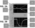
- Figure 2A schematically shows a chart of pressure over time in the system 100 of Figure 1 .
- Figure 2B schematically shows a chart of drive voltage input for the system 100 of Figure 2A over a period of seconds.
- a constant work output is maintained by a constant drive pressure produced by the microblower 110.
- the fluid path 126 may become occluded or encounter increased resistance. The increased resistance results in a build-up in the path 126, and thus, an increased pressure (shown at point 202).
- the change is pressure is approximately 0.02 PSI, a change that is considered to be effectively invisible to conventional prior art pumping systems.
- the power controller 112 is configured to keep pressure constant, and thus, the system 100 may compensate by approximately simultaneously decreasing the drive voltage input (starting at point 203).
- the power controller 112 adjusts the input power on the same time scale of the pressure sensor, which is on the order of 200 samples per second.
- the drive voltage decreases (e.g., at point 204), until it is sufficiently low (at point 204) for pressure to normalize at point 205. While the changes between input voltage 108 and pressure may not be 1:1, they generally are on the same order of magnitude and maintain proportionality.
- the power controller 112 may increase drive voltage, which increases drive pressure to maintain a constant work output of the microblower 110. When the occlusion/resistance is removed, the drive pressure has a rapid decrease (e.g., at point 206).
- the power controller 112 may be configured to increase the drive voltage (e.g., beginning at point 207) to cause pressure to return to the set value (e.g., at point 209), at which point the drive voltage remains steady (e.g., at point 210).
- illustrative embodiments of the system 100 are configured to maintain a substantially constant pressure. Because of the sensitivity of the TLCP driver 102, changes to the power input required to maintain the pressure may be substantially instantaneously observed and adjusted.
- the TLCP driver 102 detects occlusions or other resistance changes in the fluid path 126.
- the pump continues at its constant speed, and pressure against the occluded path builds up until it reaches a detectable alarm condition.
- a large pressure induced bolus in undesirably released.
- the system 100 is configured to maintain pressure constant to virtually eliminate the potential risk and dangers of a pressure induced bolus.
- the TLCP driver 102 has substantially greater pressure sensitivity, allowing for substantially faster occlusion detection.
- Figures 2A-2B refers to maintaining pressure constant within the system 100 as load changes, it should be understood that this is merely an example of how the system 100 may operate.
- the system 100 may be configured to maintain flow rate constant as load (e.g., resistance) increases.
- load e.g., resistance
- the drive voltage may thus be increased (instead of decreased as in the previous example) to further increase flow rate.
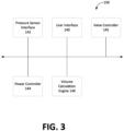
- Figure 3 schematically shows details of the fluid system controller 150 of Figure 1 configured in accordance with illustrative embodiments of the invention. Each of these components is operatively connected by any conventional interconnect mechanism. Figure 3 simply shows a bus communicating each the components. Those skilled in the art should understand that this generalized representation can be modified to include other conventional direct or indirect connections. Accordingly, discussion of a bus is not intended to limit various embodiments.
- Figure 3 only schematically shows each of these components.
- the power controller 144 may be implemented using a plurality of microprocessors executing firmware.
- the power controller 144 may be implemented using one or more application specific integrated circuits (i.e., "ASICs") and related software, or a combination of ASICs, discrete electronic components (e.g., integrated circuits), and microprocessors.
- ASICs application specific integrated circuits
- the representation of the power controller 144 and other components in a single box of Figure 3 is for simplicity purposes only.
- the power controller of Figure 3 is distributed across a plurality of different components - not necessarily within the same housing or chassis.
- Figure 3 is a significantly simplified representation of an actual fluid system controller 150.
- Those skilled in the art should understand that such a device has other physical and/or functional components, such as central processing units, other packet processing modules, and short-term memory. Accordingly, this discussion is not intended to suggest that Figure 3 represents all of the elements of the fluid system controller 150. In fact, much of what was said here with regard to Figure 3 can also be applied to components of the system 100 of Figure 1 .
- the power controller 112 controls the power input 108 provided to the microblower 110.
- the fluid system controller 150 thus instructs the power controller 112 to provide the power input 108 to the microblower 110.
- the power controller 112 controls the pressure of the output gas 104.
- the fluid system controller 150 has a user interface 140 configured to receive an input from a user.
- the user interface 140 may receive a setting of a constant pressure or a constant flow rate that the microblower 110 should output.
- the user interface 140 may be provided as a touchscreen display, a mechanical interface, and/or as a smartphone connected application.
- the fluid system controller 150 also has a pressure sensor interface 142 configured to receive pressure signals 118 from the noted pressure sensors 116A and 116B (or other pressure sensors). As described further below with reference to Figure 4 , the pressure signals 118 provide a feedback loop to the fluid system controller 150 that allows the power controller 112 to adjust the power input 108 provided to the microblower 110 as a function of the amount of pressure in one or both the gas reservoir 114 and the fluid reservoir 120.
- the feedback control loop can be substantially modified by, for example, adjusting coefficients for errors that are proportional, integrative, and derivative (PID). Such PID coefficients can even be modified during operation of the system 100, providing a wide dynamic range of behaviors.
- the fluid system controller 150 also has a TLCP power input engine 144 configured to receive the settings from the user interface 140 (e.g., a constant pressure setting), receive pressure data from the pressure sensor interface 142, and to instruct the power controller 112 to increase or decrease pressure and/or flow rate.
- the power input engine 144 performs calculations relating to what power input 108 should be provided to the microblower in accordance with the desired pressure setting in the gas reservoir and/or the fluid reservoir 144.
- the power input engine 144 then provides that information to the power controller 112, that provides the power input 108 to the microblower.
- the fluid system controller 150 has a volume calculation engine 146 configured to calculate the unknown fluid volume in the fluid reservoir 120, based on the known volume in the gas reservoir, and the known pressures in the fluid reservoir 120 and the gas reservoir 114. In some embodiments, the fluid volume calculation engine 146 may also be configured to calculate the flow rate of fluid out of the fluid reservoir 120. Additionally, or alternatively, the volume calculation engine 146 may also be configured to measure fluid going into the fluid reservoir 120. Fluid flow directional references of gas or fluids should be considered to represent flow in either direction.
- the fluid system controller 150 also has a valve controller 145 that controls the opening and closing of the valve 122.
- Figure 4A shows a process of modulating the drive pressure inside a fluid system 100 in accordance with illustrative embodiments of the invention. It should be noted that this method is substantially simplified from a longer process that may normally be used. Accordingly, the method shown in Figure 4A may have many other steps that those skilled in the art likely would use. In addition, some of the steps may be performed in a different order than that shown, or at the same time. Furthermore, some of these steps may be optional in some embodiments. Accordingly, the process 400 is merely exemplary of one process in accordance with illustrative embodiments of the invention. Those skilled in the art therefore can modify the process as appropriate.
- the process begins at step 402, which provides input power 108 to the TLCP driver 102.
- the power input 108 is provided to the TLCP driver 102, and the TLCP driver 102 begins to pump gas in accordance therewith.
- the pressure and flow of gas is a function of the input power 108.
- the input power 108 may be initially set, for example, by a user through the user interface 140.
- the microblower 110 then begins to pump the output gas 104 into the gas reservoir 114.
- the valve controller 145 optionally opens the pneumatic valve 122 between the fluid reservoir 120 and the gas reservoir 114.
- the fluid path 126 and the gas reservoir 114 thus become pneumatically coupled, and their pressures become substantially the same (e.g., because of the interface 124, which does not substantially attenuate the pressure).
- the gas drive pressure presses against the fluid at the interface 124, either directly, or via the flexible, inelastic membrane.
- the pressure in the fluid path 126 moves the fluid towards its destination 128.
- the destination 128 may be a patient in a hospital setting who is receiving an IV infusion of a particular drug.
- fluid line occlusion undesirably goes largely undetected, resulting in large bolus administrations of drug after the occlusion is removed.
- Illustrative embodiments mitigate this problem by providing a self-regulating system that controls pressure and ensures that the patient receives the prescribed drug dosage in a safe manner.
- step 408 in which the pressure sensor 116B measures the pressure in the gas reservoir and/or the fluid path to determine whether pressure is constant at the set amount.
- the system 100 is highly sensitive to even small changes in pressure (e.g., because of the lack of friction and/or mechanical gear components in the TLCP driver 102).
- the pressure readings e.g., from pressure sensor 116A and/or 116B
- the process then moves to step 410, which determines whether the pressure is constant at the specified level.
- the fluid system controller 150 determines whether there is an occlusion or resistance in the line by looking at the pressure. As described with reference to Figures 2A-2B , the fluid system controller 150 may determine whether there is occlusion/resistance in the line by noticing a change in the pressure in the system (e.g., gas reservoir, fluid reservoir, and/or fluid line). However, in some embodiments, pressure is kept constant by the system 100. Accordingly, when the line is occluded, to maintain pressure constant, input power goes down. The change in input power 108 allows the system 100 to determine changes in flow/resistance while maintaining pressure constant. Thus, the system 100 may detect an occlusion while keeping pressure constant.
- the pressure in the system e.g., gas reservoir, fluid reservoir, and/or fluid line.
- pressure is kept constant by the system 100. Accordingly, when the line is occluded, to maintain pressure constant, input power goes down. The change in input power 108 allows the system 100 to determine changes in flow/resistance while maintaining pressure
- step 412 in which the power controller 144 modulates the input power 108 toward an appropriate level.
- the fluid system controller 150 determines that the pressure is not with at the correct setting and its power controller 144 sends a signal to the power controller 112 to make a corresponding adjustment to the output power 108.
- the process 400 then returns to step 400, which again measures the pressure. If the pressure is still incorrect, the process repeats. This may occur many times, and steps 408-412 may occur substantially simultaneously (e.g., pressure readings may be taken continuously). If the pressure reading is at the appropriate setting in step 410, then the system 100 continues to step 414 and pumps the fluid to the patient at the set pressure.
- valve 122 may vary, but some embodiments open the valve 122 for a period on the order of 1 second to allow substantial equilibration between the pressure in the gas reservoir 114 and the pressure in the fluid reservoir 120. In some applications, the valve controller 145 may open the valve 122 for a small fraction of a second, allowing partial equilibrium of pressures.
- the process may optionally move to step 416, in which the volume calculation engine 146 calculates the unknown volume of fluid in the fluid reservoir 120.
- step 416 may additionally, or alternatively, be performed earlier in the process and multiple times throughout the process (e.g., in the feedback loop of steps 408-412).
- the volume calculation engine 146 may calculate the unknown volume by using, for example, the methodologies described below with reference to Figure 5 .
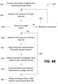
- Figure 4B shows a process 420 of calculating the unknown volume of fluid in the fluid reservoir 120 and measuring flow rate from the fluid reservoir 120 in accordance with illustrative embodiments of the invention. It should be noted that this method is substantially simplified from a longer process that may normally be used. Accordingly, the method shown in Figure 4B may have many other steps that those skilled in the art likely would use. In addition, some of the steps may be performed in a different order than that shown, or at the same time. Furthermore, some of these steps may be optional in some embodiments. Accordingly, the process 420 is merely exemplary of one process in accordance with illustrative embodiments of the invention. Those skilled in the art therefore can modify the process as appropriate.
- the process 420 begins at step 422 by providing the power input 108 to the TLCP driver 102. As described previously, this target pressure may be set by the user using the user interface 140.
- the process measures the pressure in the gas reservoir 114 using the pressure sensor 116A.
- the pressure sensor 116A passes the pressure data to the pressure sensor interface 142, and the fluid system controller 150 uses this data at step 426 to determine whether the pressure is at the target level.
- step 428 the input power 108 is modulated. This adjustment either increases or decreases the gas pressure output by the TLCP driver 102. This process may be repeated until the pressure in the gas reservoir 114 is at the target level. After the pressure in the gas reservoir 114 reaches the target level, the process proceeds to step 430, where the pressure in the fluid reservoir 120 is measured by the pressure sensor 116B. At this point in the process, the gas reservoir 114 and the fluid reservoir 120 are pneumatically isolated. The pressure data is fed to the fluid system controller 150 through the pressure sensor interface 142.
- the valve controller 145 opens the pneumatic valve 122 between the fluid reservoir 120 and the gas reservoir 114 to pneumatically couples the reservoirs.
- the valve controller 145 may receive an indication of when to open and close the valve 122 from the volume calculation engine 146.
- pneumatically coupling the reservoirs 114 and 120 causes them to have substantially the same internal pressure.
- the process measures the pressure (or the pressure changes) in each of the reservoirs 114 and 120, and the volume calculation engine 146 uses this data to compute the unknown gas volume in the fluid reservoir 120 based on the change in pressure.
- the volume calculation engine 146 may then subtract the calculated gas volume from the total known volume of the fluid reservoir 120 (e.g., 60 mL syringe housing) to calculate the previously unknown volume of fluid within the fluid reservoir 120.
- step 436 the valve controller 145 closes the pneumatic valve 122 between the fluid reservoir 120 and the gas reservoir 114.
- the reservoirs 114 and 120 are no longer pneumatically coupled, and thus, pressure changes within one reservoir does not affect the pressure in the other reservoir.
- the pressure sensor 116B detects a pressure drop.
- the volume calculation engine 146 may use this change in pressure along with the previously calculated volume from step 434 to determine the flow rate of the fluid from the fluid reservoir 120 (i.e., by watching the pressure "leak").
- the process 420 may measure fluid flow by periodically calculating (e.g., every minute) the volume of liquid in the liquid reservoir 120 using the feedback loop 440.
- the valve 122 may be reopened to combine the pressures of the two reservoirs 114 and 120, the volume calculation engine 146 may use the pressure change to calculate the volume of liquid in the liquid reservoir 120, and the change in volume may be used to determine flow rate at discrete sampling intervals. This process may be repeated for a plurality of cycles (e.g., by reopening the valve 122, taking a pressure measurement to calculate volume loss, and reclosing the valve 122).
- Figure 5 provides an example of the volume calculations made by the volume calculation engine 146 in accordance with illustrative embodiments of the invention.
- the following examples are provided as an exemplary embodiment of the gas volume-based calculations that can be made by the system 100.
- the system 100 has a known volume (e.g., the gas reservoir 114) or a known volume change and an unknown volume.
- Illustrative embodiments also measure the pressures of the known volume(s) (or known volume changes) and the unknown volume(s), individually and after they are pneumatically combined according to the forgoing methods and modes of operation of the system 100.
- FIG. 5 Three examples are provided in the table of Figure 5 with a known volume (e.g., the gas reservoir 114) of 600 microliters (mcL), and three respective (and different), unknown volumes-600 mcL, 300mcL, and 1200 mcL.
- the figure shows the pressure signals 118 taken from the first pressure sensor 116A for the gas reservoir 114 and the second pressure sensor 116B for the resulting combined known (gas reservoir 114) and unknown (fluid reservoir 120) volumes, sitting respectfully at knowable and measurable pressures, and occurring at roughly time "7" on the x-axis timeline of the figure.
- the resulting combined pressure is expected to be the average of the two.
- the second example labeled "300" (mcL) in the table and "VOL 300" in Figure 5 also shows an initial gauge pressure of 1 PSIg for the known volume (reference volume 114).
- the unknown volume has a measured (by the second pressure sensor 116B) gauge pressure of 0 PSIg.
- the resulting final pressure of the combined volumes is measured to be 0.667 PSIg.
- the third example labeled “1200" (mcL) in the table and "VOL 1200" in the figure also shows an initial gauge pressure of 1 PSIg for the known volume (reference volume 114).
- the unknown volume has a measured (by second sensor 116B) gauge pressure of 0 PSIg.
- the resulting final pressure of the combined volumes is measured to be 0.333 PSIg.
- the measured atmospheric pressure is 14.700 PSIa; the known volume is 600 mcL (although the unit of measure is not relevant in this verification); the unknown volume is 600 mcL.
- illustrative embodiments may be applied to a broad and complex set of use cases by adding additional pneumatic drive components. For example, to deliver liquid to multiple channels in a parenteral nutrition pharmacy compounder, a discrete set of pneumatic drive components may be added to each channel.
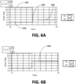
- Figures 6A-6C show examples of pressure measurements in the gas reservoir 114 and the fluid reservoir 120 before and after they are pneumatically coupled in accordance with illustrative embodiments of the invention.
- the gas reservoir 114 has a know volume and a measured pressure 601.
- the fluid reservoir 120 has an unknown volume and a measure pressure 602.
- pressures 602 and 607 are at 0 PSIg merely because they had been opened to atmosphere prior to the process.
- the analysis of pressure changes do not require any restriction on the initial conditions, except that the pressures in the gas and fluid reservoirs 114 and 120 are different than each other prior to the opening of valve 122.
- valve 122 is activated to pneumatically join the two reservoirs 114 and 120, and the two pressures combine to have a measured pressure 604.
- the relationship between the measured pressures of both reservoirs 114 and 120 and the known volume of one reservoir 114 can be used to calculate the volume of the other reservoir 120.
- Figure 6B shows a different example of the fluid reservoir 120 being joined with the gas reservoir 114.
- the volume of the gas reservoir 114 may be known. Joining the two reservoirs 114 and 120 results in a joined pressure 605.
- the reservoir with the larger volume has a greater overall effect on joined pressure.
- the larger volume is the fluid reservoir 120, whereas in Figure 6B , the two volumes are about the same.
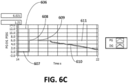
- the gas reservoir 114 has a known volume and a measured pressure 606.
- the fluid reservoir 120 has an unknown liquid volume and a measured pressure 607.
- the valve 122 is activated to pneumatically join the two reservoirs 114 and 120.
- the resultant pressure 609 can be measured, and the unknown liquid volume can be calculated by the volume calculation engine 146.
- the pneumatic valve 122 may be closed by the valve controller 145.
- each reservoir remains pressurized at substantially the same pressure as when the reservoirs 114 and 120 were coupled.
- the pressure in the fluid reservoir 120 decreases. This change in pressure is shown in line 610, whereas the pressure in the gas reservoir 114 remains constant (shown by line 611).
- the change in absolute pressure represents the proportional change in volume over time, or flow.
- the volume calculation engine 146 may be used to calculate flow out of the system 100 over the time (i.e., fluid flow rate).
- illustrative embodiments provide a number of advantages. For example, illustrative embodiments include a much more rapid and precise response to pressure changes over prior art pumps known to the inventors. This is, for example, because some conventional pumps have a small motor and a gear box. Illustrative embodiments provide a high-frequency, self-resonating driver where a change in the load is seen directly by the system 100. Because there is no substantial interference with the coupling between the drive pressure and the liquid in the fluid reservoir (including the interface 124 which is flexible and negligible) when the valve 122 is open, the gas pressure is substantially the same as the liquid pressure. This intimate connection allows the system 100 to be delicately balanced. A further advantage of the system 100 is that line occlusion and/or changes in resistance may be detected while keeping pressure constant (e.g., by detecting a change in input power 108).
- fluid encompasses liquids.
- liquid may be applied throughout the previous description to replace the term “fluid,” for example, to refer to the fluid reservoir 120 and the gas-fluid interface 124.
- embodiments of the invention may be implemented at least in part in any conventional computer programming language. For example, some embodiments may be implemented in a procedural programming language (e.g., "C"), or in an object oriented programming language (e.g., "C++"). Other embodiments of the invention may be implemented as preprogrammed hardware elements (e.g., application specific integrated circuits, FPGAs, programmable analog circuitry, and digital signal processors), or other related components.
- a procedural programming language e.g., "C”
- object oriented programming language e.g., "C++”
- preprogrammed hardware elements e.g., application specific integrated circuits, FPGAs, programmable analog circuitry, and digital signal processors
- the disclosed apparatus and methods may be implemented as a computer program product for use with a computer system.
- Such implementation may include a series of computer instructions fixed either on a tangible, non-transitory medium, such as a computer readable medium (e.g., a diskette, CD-ROM, ROM, or fixed disk).
- a computer readable medium e.g., a diskette, CD-ROM, ROM, or fixed disk.
- the series of computer instructions can embody all or part of the functionality previously described herein with respect to the system.
- Such computer instructions can be written in a number of programming languages for use with many computer architectures or operating systems.
- such instructions may be stored in any memory device, such as semiconductor, magnetic, optical or other memory devices, and may be transmitted using any communications technology, such as optical, infrared, microwave, or other transmission technologies.
- such a computer program product may be distributed as a removable medium with accompanying printed or electronic documentation (e.g., shrink wrapped software), preloaded with a computer system (e.g., on system ROM or fixed disk), or distributed from a server or electronic bulletin board over the network (e.g., the Internet or World Wide Web).
- a computer system e.g., on system ROM or fixed disk
- a server or electronic bulletin board over the network
- some embodiments may be implemented in a software-as-a-service model ("SAAS") or cloud computing model.
- SAAS software-as-a-service model
- some embodiments of the invention may be implemented as a combination of both software (e.g., a computer program product) and hardware. Still other embodiments of the invention are implemented as entirely hardware, or entirely software.
- Disclosed embodiments, or portions thereof, may be combined in ways not listed above and/or not explicitly claimed.
- embodiments disclosed herein may be suitably practiced, absent any element that is not specifically disclosed herein. Accordingly, the invention should not be viewed as being limited to the disclosed embodiments.
Landscapes
- Engineering & Computer Science (AREA)
- Physics & Mathematics (AREA)
- General Physics & Mathematics (AREA)
- Fluid Mechanics (AREA)
- Automation & Control Theory (AREA)
- Mechanical Engineering (AREA)
- General Engineering & Computer Science (AREA)
- Infusion, Injection, And Reservoir Apparatuses (AREA)
Claims (15)
- System (100) zur präzisen Flüssigkeitsabgabe, wobei das System Folgendes umfasst:einen Gasbehälter (114), der ein bekanntes Volumen aufweist;einen dicht lastgekoppelten pneumatischen, TLCP-, Treiber (102), der konfiguriert ist zum Aufnehmen von Eingangsleistung, die bewirkt, dass der TLCP-Treiber Gas in den Gasbehälter bewegt, um einen Gasantriebsdruck zu erzeugen;ein Ventil (122), das konfiguriert ist zum Koppeln des Gasbehälters mit einem Fluidbehälter (120), der ein unbekanntes Volumen einer Flüssigkeit aufweist, wobei das Ventil weiter konfiguriert ist zum selektiven pneumatischen Isolieren und pneumatischen Koppeln von Drücken in dem Gasbehälter und dem Fluidbehälter;eine Gas-Fluid-Schnittstelle (124), die konfiguriert ist zum Koppeln von Druck im Fluidbehälter mit Druck in einem Fluidweg (126), wobei der Fluidweg so konfiguriert ist, dass der Fluidantriebsdruck, der Flüssigkeit in den Fluidweg treibt, im Wesentlichen gleich ist wie der Fluidbehälterdruck; undeinen Drucksensor (116A, 116B), der konfiguriert ist zum Erkennen von Druck im Gasbehälter und/oder dem Fluidbehälter.
- System nach Anspruch 1, weiter umfassend eine Leistungssteuereinheit (112), die konfiguriert ist zum Steuern der Eingangsleistung in den TLCP-Treiber, um den Gasantriebsdruck anzupassen,wobei der Gasantriebsdruck bewirkt, dass sich die Flüssigkeit im Fluidweg mit einer ausgewählten Strömungsgeschwindigkeit bewegt, wenn das Ventil die Drücke im Gasbehälter und im Fluidbehälter pneumatisch koppelt, unddie Leistungssteuereinheit konfiguriert ist zum Steuern der Eingangsleistung in den TLCP-Treiber, um den Gasantriebsdruck so anzupassen, dass die ausgewählte Strömungsgeschwindigkeit erreicht wird.
- System nach Anspruch 1, weiter umfassend eine Volumenberechnungs-Engine (146), die angepasst ist zum Berechnen von Fluidströmung als Funktion einer entsprechenden Änderung der Eingangsleistung, während der Druck im Wesentlichen konstant bleibt.
- System nach Anspruch 1, wobei der Gasantriebsdruck als Funktion der Höhe des Drucks in einem oder beiden des Gasbehälters und des Fluidbehälters angepasst wird.
- System nach Anspruch 1, wobei der TLCP-Treiber aus piezoelektrischem Material gebildet ist; und wobei der TLCP-Treiber optional ein Mikrogebläse (110) umfasst.
- System nach Anspruch 1, wobei die Gas-Fluid-Schnittstelle eine flexible Membran umfasst, die so konfiguriert ist, dass sie keine Dehnkräfte auferlegt.
- System nach Anspruch 1, weiter umfassend ein zweites Ventil, das so konfiguriert ist, dass es den TLCP-Treiber und den Gasbehälter selektiv isoliert oder pneumatisch koppelt.
- System nach Anspruch 1, wobei die Leistungssteuereinheit betriebsfähig mit dem Drucksensor gekoppelt ist zum Aufnehmen der Höhe des Drucks von einem oder beiden des Gasbehälters und des Fluidbehälters.
- Verfahren zum Bestimmen von Fluidströmungsmerkmalen in einem Flüssigkeitsabgabesystem (100) nach einem der Ansprüche 1 bis 8, wobei das Verfahren Folgendes umfasst:Erzeugen (422) eines Gasantriebsdrucks mit einem vorgegebenen Wert von einem dicht lastgekoppelten pneumatischen, TLCP-, Treiber (102) durch Bereitstellen einer Eingangsleistung, um Gas in einen Gasbehälter (114) zu bewegen, der ein bekanntes Volumen aufweist, wobei der Gasantriebsdruck konfiguriert ist zum Bewegen von Fluid in einem Fluidbehälter (120);Messen (424) des Drucks im Gasbehälter, um einen Gasbehälterdruck bereitzustellen;Messen (430) des Drucks im Fluidbehälter, um einen Fluidbehälterdruck bereitzustellen;pneumatisches Koppeln (432) des Gasbehälters und des Fluidbehälters durch Öffnen eines Ventils (122) dazwischen, sodass der Gasbehälterdruck und der Fluidbehälterdruck im Wesentlichen gleich werden;Messen (434) eines Drucks im Gasbehälter und/oder im Fluidbehälter, nachdem der Gasbehälter und der Fluidbehälter pneumatisch gekoppelt wurden;Berechnen (434) einer Druckänderung im Gasbehälter;Berechnen (434) einer Druckänderung im Fluidbehälter;Berechnen (434) des Flüssigkeitsvolumens innerhalb des Fluidbehälters als Funktion der Druckänderung im Fluidbehälter und im Gasbehälter; undpneumatisches Isolieren (436) des Gasbehälters und des Fluidbehälters durch Schließen des Ventils dazwischen.
- Verfahren nach Anspruch 9, weiter umfassend:
Messen (438) der Druckänderung im Fluidbehälter während Fluid durch einen Fluidweg strömt, um eine Strömungsgeschwindigkeit zu bestimmen. - Verfahren nach Anspruch 9, weiter umfassend:
Erkennen einer Verstopfung im Fluidweg durch Messen einer Änderung der Eingangsleistung, die verwendet wird, um den Gasantriebsdruck auf dem vorgegebenen Wert zu halten. - Verfahren nach Anspruch 9, weiter umfassend;Erkennen einer Änderung der geleisteten Ausgabe des TLCP-Treibers von 0,1 bis 1,0 Prozent; undSteuern der Eingangsleistung in den TLCP-Treiber, um die geleistete Ausgabe konstant zu halten.
- Computerprogrammprodukt zur Verwendung in einem Computersystem für präzise Flüssigkeitsabgabe, wobei das Computerprogrammprodukt ein materielles nicht flüchtiges computernutzbares Medium umfasst, das darauf computerlesbaren Programmcode aufweist, wobei der Programmcode Folgendes umfasst:Programmcode zum Bereitstellen einer Eingangsleistung in einen dicht lastgekoppelten pneumatischen, TLCP-, Treiber (102), um einen Gasantriebsdruck zu erzeugen, der Gas in einen Gasbehälter (114) bewegt;Programmcode zum pneumatischen Koppeln des Gasbehälters und eines Fluidbehälters (120) durch Öffnen eines Ventils (122) dazwischen, sodass der Gasbehälterdruck und der Fluidbehälterdruck im Wesentlichen gleich werden;Programmcode zum pneumatischen Isolieren des Gasbehälters und des Fluidbehälters durch Schließen des Ventils dazwischen;Programmcode, um zu bewirken, dass ein oder mehrere Drucksensoren (116A, 116B) Druck im Gasbehälter und im Fluidbehälter a) vor pneumatischem Koppeln des Gasbehälters und des Fluidbehälters, und b) nach pneumatischem Koppeln des Gasbehälters und des Fluidbehälters messen; undProgrammcode zum Berechnen eines Volumens einer unbekannten Flüssigkeit im Fluidbehälter.
- Computerprogrammprodukt nach Anspruch 13, weiter umfassend: Programmcode zum Berechnen der Strömungsgeschwindigkeit aus dem Fluidbehälter; und wobei die Strömungsgeschwindigkeitsberechnung optional durchgeführt wird durch (a) Messen von Druckabfällen im Fluidbehälter und Korrelieren der Druckabfälle mit Strömungsgeschwindigkeit, und/oder (b) Neuberechnen des Volumens im Fluidbehälter zu einem späteren Zeitpunkt.
- Computerprogrammprodukt nach Anspruch 13, wobei eine Änderung der Fluidströmung von dem Fluidweg eine entsprechende Änderung der Eingangsleistung in den TLCP-Treiber bewirkt, um den Gasantriebsdruck und den Fluidantriebsdruck konstant zu halten.
Applications Claiming Priority (2)
| Application Number | Priority Date | Filing Date | Title |
|---|---|---|---|
| US201862746558P | 2018-10-17 | 2018-10-17 | |
| PCT/US2019/056783 WO2020081846A1 (en) | 2018-10-17 | 2019-10-17 | Airflow-based volumetric pump |
Publications (3)
| Publication Number | Publication Date |
|---|---|
| EP3867190A1 EP3867190A1 (de) | 2021-08-25 |
| EP3867190A4 EP3867190A4 (de) | 2022-07-13 |
| EP3867190B1 true EP3867190B1 (de) | 2024-09-18 |
Family
ID=70279151
Family Applications (1)
| Application Number | Title | Priority Date | Filing Date |
|---|---|---|---|
| EP19872718.2A Active EP3867190B1 (de) | 2018-10-17 | 2019-10-17 | Luftströmungsbasierte volumetrische pumpe |
Country Status (3)
| Country | Link |
|---|---|
| US (2) | US11550345B2 (de) |
| EP (1) | EP3867190B1 (de) |
| WO (1) | WO2020081846A1 (de) |
Families Citing this family (4)
| Publication number | Priority date | Publication date | Assignee | Title |
|---|---|---|---|---|
| WO2020081846A1 (en) | 2018-10-17 | 2020-04-23 | Pneuma Systems Corporation | Airflow-based volumetric pump |
| WO2022006132A2 (en) | 2020-06-29 | 2022-01-06 | Carlisle Jeffrey A | Simplified pneumatic volumetric pump using iv drip chamber |
| US20220118178A1 (en) * | 2020-10-20 | 2022-04-21 | Pneuma Systems Corporation | Iv gravity delivery monitor |
| GB2612629A (en) * | 2021-11-08 | 2023-05-10 | Lee Ventus Ltd | Fluid control system |
Family Cites Families (27)
| Publication number | Priority date | Publication date | Assignee | Title |
|---|---|---|---|---|
| JPS5629277B2 (de) * | 1972-08-14 | 1981-07-07 | ||
| AU1678595A (en) * | 1994-01-14 | 1995-08-01 | Unit Instruments, Inc. | Flow meter |
| US6604908B1 (en) | 1999-07-20 | 2003-08-12 | Deka Products Limited Partnership | Methods and systems for pulsed delivery of fluids from a pump |
| ATE283077T1 (de) * | 2000-03-27 | 2004-12-15 | Cleveland Clinic Foundation | Chronisches leistungssteuerungssystem für rotodynamische blutpumpe |
| DE10022398B4 (de) | 2000-04-28 | 2011-03-17 | Eppendorf Ag | Gaspolster-Mikrodosiersystem |
| ES2342456T3 (es) * | 2001-02-22 | 2010-07-07 | Terumo Kabushiki Kaisha | Bomba de jeringuilla. |
| US20030105536A1 (en) * | 2001-12-04 | 2003-06-05 | Eastman Kodak Company | Open and closed loop flow control system and method |
| JP4861692B2 (ja) | 2005-12-02 | 2012-01-25 | 日本エア・リキード株式会社 | 液体材料の定量供給方法 |
| JP2008039513A (ja) * | 2006-08-03 | 2008-02-21 | Hitachi Metals Ltd | 質量流量制御装置の流量制御補正方法 |
| US8162000B2 (en) * | 2006-12-13 | 2012-04-24 | Novartis Ag | Adjustable pneumatic system for a surgical machine |
| US8366658B2 (en) | 2010-05-06 | 2013-02-05 | Becton, Dickinson And Company | Systems and methods for providing a closed venting hazardous drug IV set |
| US8206378B1 (en) * | 2011-04-13 | 2012-06-26 | Medtronic, Inc. | Estimating the volume of fluid in therapeutic fluid delivery device reservoir |
| JP2014515339A (ja) | 2011-05-23 | 2014-06-30 | ストレワット | 流体を貯蔵および送出するためのデバイスならびにかかるデバイス内に収容された圧縮ガスを貯蔵および送出するための方法 |
| JP5629277B2 (ja) | 2012-01-12 | 2014-11-19 | 日立アロカメディカル株式会社 | 液体調合装置 |
| US9220834B2 (en) | 2012-12-20 | 2015-12-29 | Acist Medical Systems, Inc. | Pressure sensing in medical injection systems |
| CN104937281B (zh) | 2013-01-18 | 2016-09-14 | 株式会社村田制作所 | 加压式液体提升装置以及液体提升方法 |
| US9867931B2 (en) | 2013-10-02 | 2018-01-16 | Cook Medical Technologies Llc | Therapeutic agents for delivery using a catheter and pressure source |
| KR102431008B1 (ko) | 2013-05-23 | 2022-08-09 | 뉴아이브이 메디컬 코퍼레이션 | 공압적으로 결합된 직접 구동 유체 제어 시스템 및 방법 |
| WO2015134651A1 (en) | 2014-03-07 | 2015-09-11 | Carefusion 303, Inc. | Syringe flush protection valve and method |
| US10458833B2 (en) * | 2014-05-16 | 2019-10-29 | Sorin Group Italia S.R.L. | Blood reservoir with fluid volume measurement based on pressure sensor |
| DE102015205124A1 (de) | 2015-03-20 | 2016-09-22 | BSH Hausgeräte GmbH | Heißgetränkezubereitungsvorrichtung, insbesondere Kaffeevollautomat, und Verfahren zu ihrem Betrieb |
| DE202018006777U1 (de) | 2017-06-15 | 2022-12-14 | Chiaro Technology Limited | Brustpumpensystem |
| CN208726441U (zh) | 2018-04-19 | 2019-04-12 | 郑州大学第一附属医院 | 输液辅助器 |
| WO2020081846A1 (en) | 2018-10-17 | 2020-04-23 | Pneuma Systems Corporation | Airflow-based volumetric pump |
| CN211327440U (zh) | 2019-09-06 | 2020-08-25 | 吴敏 | 一种实时监测滴壶液体量的输液组件 |
| WO2022006132A2 (en) | 2020-06-29 | 2022-01-06 | Carlisle Jeffrey A | Simplified pneumatic volumetric pump using iv drip chamber |
| US20220118178A1 (en) | 2020-10-20 | 2022-04-21 | Pneuma Systems Corporation | Iv gravity delivery monitor |
-
2019
- 2019-10-17 WO PCT/US2019/056783 patent/WO2020081846A1/en not_active Ceased
- 2019-10-17 EP EP19872718.2A patent/EP3867190B1/de active Active
- 2019-10-17 US US16/656,449 patent/US11550345B2/en active Active
-
2022
- 2022-12-13 US US18/080,469 patent/US11914401B2/en active Active
Also Published As
| Publication number | Publication date |
|---|---|
| EP3867190A1 (de) | 2021-08-25 |
| WO2020081846A1 (en) | 2020-04-23 |
| US20230115695A1 (en) | 2023-04-13 |
| US11914401B2 (en) | 2024-02-27 |
| US20200125124A1 (en) | 2020-04-23 |
| US11550345B2 (en) | 2023-01-10 |
| EP3867190A4 (de) | 2022-07-13 |
Similar Documents
| Publication | Publication Date | Title |
|---|---|---|
| US11914401B2 (en) | Airflow-based volumetric pump | |
| US7654127B2 (en) | Malfunction detection in infusion pumps | |
| US20070062251A1 (en) | Infusion Pump With Closed Loop Control and Algorithm | |
| US8986253B2 (en) | Two chamber pumps and related methods | |
| US9459128B2 (en) | Device and method for dispensing or receiving a liquid volume | |
| US20080196762A1 (en) | Systems and methods for the accurate delivery of flow materials | |
| CN208481811U (zh) | 用于检测药物流体连通系统中的流体特性的系统 | |
| US7944366B2 (en) | Malfunction detection with derivative calculation | |
| US20070264130A1 (en) | Infusion Pumps and Methods for Use | |
| CN110088472B (zh) | 医用液体的容积泵和血液治疗设备及其控制的方法 | |
| EP2242421A2 (de) | Zweikammerpumpen und verwandte verfahren | |
| CN106855429A (zh) | 微量配量给料系统 | |
| JP7387441B2 (ja) | ポンプシステム、透析装置、及びポンプシステムの作動方法 | |
| EP4551272A1 (de) | System und verfahren zur drucksensorbasierten gasblasendetektion für eine arzneimittelabgabevorrichtung | |
| US12201805B2 (en) | Simplified pneumatic volumetric pump using IV drip chamber | |
| US20110152697A1 (en) | Circulatory Pressure Monitoring Using Infusion Pump Systems | |
| CN108474366B (zh) | 包括具有隔膜泵和阀的配给管路的血液治疗仪和用于配给的方法 | |
| CA2783607A1 (en) | Circulatory pressure monitoring using infusion pump systems | |
| US20250345529A1 (en) | System and method of detecting and managing bubbles in fluid lines | |
| WO2023079314A1 (en) | Fluid control system | |
| WO2021076826A3 (en) | Drug delivery device and system |
Legal Events
| Date | Code | Title | Description |
|---|---|---|---|
| STAA | Information on the status of an ep patent application or granted ep patent |
Free format text: STATUS: THE INTERNATIONAL PUBLICATION HAS BEEN MADE |
|
| PUAI | Public reference made under article 153(3) epc to a published international application that has entered the european phase |
Free format text: ORIGINAL CODE: 0009012 |
|
| STAA | Information on the status of an ep patent application or granted ep patent |
Free format text: STATUS: REQUEST FOR EXAMINATION WAS MADE |
|
| 17P | Request for examination filed |
Effective date: 20210415 |
|
| AK | Designated contracting states |
Kind code of ref document: A1 Designated state(s): AL AT BE BG CH CY CZ DE DK EE ES FI FR GB GR HR HU IE IS IT LI LT LU LV MC MK MT NL NO PL PT RO RS SE SI SK SM TR |
|
| DAV | Request for validation of the european patent (deleted) | ||
| DAX | Request for extension of the european patent (deleted) | ||
| A4 | Supplementary search report drawn up and despatched |
Effective date: 20220614 |
|
| RIC1 | Information provided on ipc code assigned before grant |
Ipc: G05D 7/06 20060101ALI20220609BHEP Ipc: F04F 1/06 20060101ALI20220609BHEP Ipc: F04B 43/073 20060101ALI20220609BHEP Ipc: F04B 13/00 20060101ALI20220609BHEP Ipc: G05B 19/042 20060101ALI20220609BHEP Ipc: G01F 11/28 20060101ALI20220609BHEP Ipc: G01F 22/02 20060101ALI20220609BHEP Ipc: A61M 5/14 20060101ALI20220609BHEP Ipc: B67D 7/72 20100101ALI20220609BHEP Ipc: B67D 7/32 20100101ALI20220609BHEP Ipc: B67D 7/08 20100101ALI20220609BHEP Ipc: B67D 7/02 20100101AFI20220609BHEP |
|
| GRAP | Despatch of communication of intention to grant a patent |
Free format text: ORIGINAL CODE: EPIDOSNIGR1 |
|
| STAA | Information on the status of an ep patent application or granted ep patent |
Free format text: STATUS: GRANT OF PATENT IS INTENDED |
|
| INTG | Intention to grant announced |
Effective date: 20231024 |
|
| GRAJ | Information related to disapproval of communication of intention to grant by the applicant or resumption of examination proceedings by the epo deleted |
Free format text: ORIGINAL CODE: EPIDOSDIGR1 |
|
| STAA | Information on the status of an ep patent application or granted ep patent |
Free format text: STATUS: REQUEST FOR EXAMINATION WAS MADE |
|
| INTC | Intention to grant announced (deleted) | ||
| GRAP | Despatch of communication of intention to grant a patent |
Free format text: ORIGINAL CODE: EPIDOSNIGR1 |
|
| STAA | Information on the status of an ep patent application or granted ep patent |
Free format text: STATUS: GRANT OF PATENT IS INTENDED |
|
| INTG | Intention to grant announced |
Effective date: 20240417 |
|
| GRAS | Grant fee paid |
Free format text: ORIGINAL CODE: EPIDOSNIGR3 |
|
| GRAA | (expected) grant |
Free format text: ORIGINAL CODE: 0009210 |
|
| STAA | Information on the status of an ep patent application or granted ep patent |
Free format text: STATUS: THE PATENT HAS BEEN GRANTED |
|
| AK | Designated contracting states |
Kind code of ref document: B1 Designated state(s): AL AT BE BG CH CY CZ DE DK EE ES FI FR GB GR HR HU IE IS IT LI LT LU LV MC MK MT NL NO PL PT RO RS SE SI SK SM TR |
|
| REG | Reference to a national code |
Ref country code: GB Ref legal event code: FG4D |
|
| REG | Reference to a national code |
Ref country code: CH Ref legal event code: EP |
|
| REG | Reference to a national code |
Ref country code: DE Ref legal event code: R096 Ref document number: 602019059244 Country of ref document: DE |
|
| REG | Reference to a national code |
Ref country code: IE Ref legal event code: FG4D |
|
| REG | Reference to a national code |
Ref country code: LT Ref legal event code: MG9D |
|
| PG25 | Lapsed in a contracting state [announced via postgrant information from national office to epo] |
Ref country code: NO Free format text: LAPSE BECAUSE OF FAILURE TO SUBMIT A TRANSLATION OF THE DESCRIPTION OR TO PAY THE FEE WITHIN THE PRESCRIBED TIME-LIMIT Effective date: 20241218 |
|
| PG25 | Lapsed in a contracting state [announced via postgrant information from national office to epo] |
Ref country code: GR Free format text: LAPSE BECAUSE OF FAILURE TO SUBMIT A TRANSLATION OF THE DESCRIPTION OR TO PAY THE FEE WITHIN THE PRESCRIBED TIME-LIMIT Effective date: 20241219 Ref country code: FI Free format text: LAPSE BECAUSE OF FAILURE TO SUBMIT A TRANSLATION OF THE DESCRIPTION OR TO PAY THE FEE WITHIN THE PRESCRIBED TIME-LIMIT Effective date: 20240918 |
|
| PG25 | Lapsed in a contracting state [announced via postgrant information from national office to epo] |
Ref country code: BG Free format text: LAPSE BECAUSE OF FAILURE TO SUBMIT A TRANSLATION OF THE DESCRIPTION OR TO PAY THE FEE WITHIN THE PRESCRIBED TIME-LIMIT Effective date: 20240918 |
|
| PG25 | Lapsed in a contracting state [announced via postgrant information from national office to epo] |
Ref country code: LV Free format text: LAPSE BECAUSE OF FAILURE TO SUBMIT A TRANSLATION OF THE DESCRIPTION OR TO PAY THE FEE WITHIN THE PRESCRIBED TIME-LIMIT Effective date: 20240918 |
|
| PG25 | Lapsed in a contracting state [announced via postgrant information from national office to epo] |
Ref country code: HR Free format text: LAPSE BECAUSE OF FAILURE TO SUBMIT A TRANSLATION OF THE DESCRIPTION OR TO PAY THE FEE WITHIN THE PRESCRIBED TIME-LIMIT Effective date: 20240918 |
|
| REG | Reference to a national code |
Ref country code: NL Ref legal event code: MP Effective date: 20240918 |
|
| PG25 | Lapsed in a contracting state [announced via postgrant information from national office to epo] |
Ref country code: RS Free format text: LAPSE BECAUSE OF FAILURE TO SUBMIT A TRANSLATION OF THE DESCRIPTION OR TO PAY THE FEE WITHIN THE PRESCRIBED TIME-LIMIT Effective date: 20241218 |
|
| PG25 | Lapsed in a contracting state [announced via postgrant information from national office to epo] |
Ref country code: RS Free format text: LAPSE BECAUSE OF FAILURE TO SUBMIT A TRANSLATION OF THE DESCRIPTION OR TO PAY THE FEE WITHIN THE PRESCRIBED TIME-LIMIT Effective date: 20241218 Ref country code: NO Free format text: LAPSE BECAUSE OF FAILURE TO SUBMIT A TRANSLATION OF THE DESCRIPTION OR TO PAY THE FEE WITHIN THE PRESCRIBED TIME-LIMIT Effective date: 20241218 Ref country code: LV Free format text: LAPSE BECAUSE OF FAILURE TO SUBMIT A TRANSLATION OF THE DESCRIPTION OR TO PAY THE FEE WITHIN THE PRESCRIBED TIME-LIMIT Effective date: 20240918 Ref country code: HR Free format text: LAPSE BECAUSE OF FAILURE TO SUBMIT A TRANSLATION OF THE DESCRIPTION OR TO PAY THE FEE WITHIN THE PRESCRIBED TIME-LIMIT Effective date: 20240918 Ref country code: GR Free format text: LAPSE BECAUSE OF FAILURE TO SUBMIT A TRANSLATION OF THE DESCRIPTION OR TO PAY THE FEE WITHIN THE PRESCRIBED TIME-LIMIT Effective date: 20241219 Ref country code: FI Free format text: LAPSE BECAUSE OF FAILURE TO SUBMIT A TRANSLATION OF THE DESCRIPTION OR TO PAY THE FEE WITHIN THE PRESCRIBED TIME-LIMIT Effective date: 20240918 Ref country code: BG Free format text: LAPSE BECAUSE OF FAILURE TO SUBMIT A TRANSLATION OF THE DESCRIPTION OR TO PAY THE FEE WITHIN THE PRESCRIBED TIME-LIMIT Effective date: 20240918 |
|
| REG | Reference to a national code |
Ref country code: AT Ref legal event code: MK05 Ref document number: 1724566 Country of ref document: AT Kind code of ref document: T Effective date: 20240918 |
|
| PG25 | Lapsed in a contracting state [announced via postgrant information from national office to epo] |
Ref country code: NL Free format text: LAPSE BECAUSE OF FAILURE TO SUBMIT A TRANSLATION OF THE DESCRIPTION OR TO PAY THE FEE WITHIN THE PRESCRIBED TIME-LIMIT Effective date: 20240918 |
|
| PG25 | Lapsed in a contracting state [announced via postgrant information from national office to epo] |
Ref country code: PT Free format text: LAPSE BECAUSE OF FAILURE TO SUBMIT A TRANSLATION OF THE DESCRIPTION OR TO PAY THE FEE WITHIN THE PRESCRIBED TIME-LIMIT Effective date: 20250120 Ref country code: IS Free format text: LAPSE BECAUSE OF FAILURE TO SUBMIT A TRANSLATION OF THE DESCRIPTION OR TO PAY THE FEE WITHIN THE PRESCRIBED TIME-LIMIT Effective date: 20250118 |
|
| PG25 | Lapsed in a contracting state [announced via postgrant information from national office to epo] |
Ref country code: RO Free format text: LAPSE BECAUSE OF FAILURE TO SUBMIT A TRANSLATION OF THE DESCRIPTION OR TO PAY THE FEE WITHIN THE PRESCRIBED TIME-LIMIT Effective date: 20240918 Ref country code: SM Free format text: LAPSE BECAUSE OF FAILURE TO SUBMIT A TRANSLATION OF THE DESCRIPTION OR TO PAY THE FEE WITHIN THE PRESCRIBED TIME-LIMIT Effective date: 20240918 |
|
| PG25 | Lapsed in a contracting state [announced via postgrant information from national office to epo] |
Ref country code: ES Free format text: LAPSE BECAUSE OF FAILURE TO SUBMIT A TRANSLATION OF THE DESCRIPTION OR TO PAY THE FEE WITHIN THE PRESCRIBED TIME-LIMIT Effective date: 20240918 |
|
| PG25 | Lapsed in a contracting state [announced via postgrant information from national office to epo] |
Ref country code: EE Free format text: LAPSE BECAUSE OF FAILURE TO SUBMIT A TRANSLATION OF THE DESCRIPTION OR TO PAY THE FEE WITHIN THE PRESCRIBED TIME-LIMIT Effective date: 20240918 Ref country code: AT Free format text: LAPSE BECAUSE OF FAILURE TO SUBMIT A TRANSLATION OF THE DESCRIPTION OR TO PAY THE FEE WITHIN THE PRESCRIBED TIME-LIMIT Effective date: 20240918 |
|
| PG25 | Lapsed in a contracting state [announced via postgrant information from national office to epo] |
Ref country code: PL Free format text: LAPSE BECAUSE OF FAILURE TO SUBMIT A TRANSLATION OF THE DESCRIPTION OR TO PAY THE FEE WITHIN THE PRESCRIBED TIME-LIMIT Effective date: 20240918 Ref country code: CZ Free format text: LAPSE BECAUSE OF FAILURE TO SUBMIT A TRANSLATION OF THE DESCRIPTION OR TO PAY THE FEE WITHIN THE PRESCRIBED TIME-LIMIT Effective date: 20240918 |
|
| PG25 | Lapsed in a contracting state [announced via postgrant information from national office to epo] |
Ref country code: SK Free format text: LAPSE BECAUSE OF FAILURE TO SUBMIT A TRANSLATION OF THE DESCRIPTION OR TO PAY THE FEE WITHIN THE PRESCRIBED TIME-LIMIT Effective date: 20240918 Ref country code: IT Free format text: LAPSE BECAUSE OF FAILURE TO SUBMIT A TRANSLATION OF THE DESCRIPTION OR TO PAY THE FEE WITHIN THE PRESCRIBED TIME-LIMIT Effective date: 20240918 |
|
| REG | Reference to a national code |
Ref country code: CH Ref legal event code: PL |
|
| REG | Reference to a national code |
Ref country code: DE Ref legal event code: R097 Ref document number: 602019059244 Country of ref document: DE |
|
| PG25 | Lapsed in a contracting state [announced via postgrant information from national office to epo] |
Ref country code: MC Free format text: LAPSE BECAUSE OF FAILURE TO SUBMIT A TRANSLATION OF THE DESCRIPTION OR TO PAY THE FEE WITHIN THE PRESCRIBED TIME-LIMIT Effective date: 20240918 |
|
| PG25 | Lapsed in a contracting state [announced via postgrant information from national office to epo] |
Ref country code: DK Free format text: LAPSE BECAUSE OF FAILURE TO SUBMIT A TRANSLATION OF THE DESCRIPTION OR TO PAY THE FEE WITHIN THE PRESCRIBED TIME-LIMIT Effective date: 20240918 |
|
| PG25 | Lapsed in a contracting state [announced via postgrant information from national office to epo] |
Ref country code: LU Free format text: LAPSE BECAUSE OF NON-PAYMENT OF DUE FEES Effective date: 20241017 Ref country code: BE Free format text: LAPSE BECAUSE OF NON-PAYMENT OF DUE FEES Effective date: 20241031 |
|
| PG25 | Lapsed in a contracting state [announced via postgrant information from national office to epo] |
Ref country code: CH Free format text: LAPSE BECAUSE OF NON-PAYMENT OF DUE FEES Effective date: 20241031 |
|
| PLBE | No opposition filed within time limit |
Free format text: ORIGINAL CODE: 0009261 |
|
| STAA | Information on the status of an ep patent application or granted ep patent |
Free format text: STATUS: NO OPPOSITION FILED WITHIN TIME LIMIT |
|
| REG | Reference to a national code |
Ref country code: BE Ref legal event code: MM Effective date: 20241031 |
|
| 26N | No opposition filed |
Effective date: 20250619 |
|
| PG25 | Lapsed in a contracting state [announced via postgrant information from national office to epo] |
Ref country code: SE Free format text: LAPSE BECAUSE OF FAILURE TO SUBMIT A TRANSLATION OF THE DESCRIPTION OR TO PAY THE FEE WITHIN THE PRESCRIBED TIME-LIMIT Effective date: 20240918 |
|
| PG25 | Lapsed in a contracting state [announced via postgrant information from national office to epo] |
Ref country code: IE Free format text: LAPSE BECAUSE OF NON-PAYMENT OF DUE FEES Effective date: 20241017 |
|
| PGFP | Annual fee paid to national office [announced via postgrant information from national office to epo] |
Ref country code: DE Payment date: 20251029 Year of fee payment: 7 |
|
| PGFP | Annual fee paid to national office [announced via postgrant information from national office to epo] |
Ref country code: GB Payment date: 20251027 Year of fee payment: 7 |
|
| PGFP | Annual fee paid to national office [announced via postgrant information from national office to epo] |
Ref country code: FR Payment date: 20251027 Year of fee payment: 7 |
|
| PG25 | Lapsed in a contracting state [announced via postgrant information from national office to epo] |
Ref country code: CY Free format text: LAPSE BECAUSE OF FAILURE TO SUBMIT A TRANSLATION OF THE DESCRIPTION OR TO PAY THE FEE WITHIN THE PRESCRIBED TIME-LIMIT; INVALID AB INITIO Effective date: 20191017 |
|
| PG25 | Lapsed in a contracting state [announced via postgrant information from national office to epo] |
Ref country code: HU Free format text: LAPSE BECAUSE OF FAILURE TO SUBMIT A TRANSLATION OF THE DESCRIPTION OR TO PAY THE FEE WITHIN THE PRESCRIBED TIME-LIMIT; INVALID AB INITIO Effective date: 20191017 |