EP3867541B1 - Blutpumpe - Google Patents
Blutpumpe Download PDFInfo
- Publication number
- EP3867541B1 EP3867541B1 EP19798470.1A EP19798470A EP3867541B1 EP 3867541 B1 EP3867541 B1 EP 3867541B1 EP 19798470 A EP19798470 A EP 19798470A EP 3867541 B1 EP3867541 B1 EP 3867541B1
- Authority
- EP
- European Patent Office
- Prior art keywords
- bearing
- drive shaft
- impeller
- assembly
- bearing assembly
- Prior art date
- Legal status (The legal status is an assumption and is not a legal conclusion. Google has not performed a legal analysis and makes no representation as to the accuracy of the status listed.)
- Active
Links
Images


Classifications
-
- A—HUMAN NECESSITIES
- A61—MEDICAL OR VETERINARY SCIENCE; HYGIENE
- A61M—DEVICES FOR INTRODUCING MEDIA INTO, OR ONTO, THE BODY; DEVICES FOR TRANSDUCING BODY MEDIA OR FOR TAKING MEDIA FROM THE BODY; DEVICES FOR PRODUCING OR ENDING SLEEP OR STUPOR
- A61M60/00—Blood pumps; Devices for mechanical circulatory actuation; Balloon pumps for circulatory assistance
- A61M60/10—Location thereof with respect to the patient's body
- A61M60/122—Implantable pumps or pumping devices, i.e. the blood being pumped inside the patient's body
- A61M60/126—Implantable pumps or pumping devices, i.e. the blood being pumped inside the patient's body implantable via, into, inside, in line, branching on, or around a blood vessel
- A61M60/13—Implantable pumps or pumping devices, i.e. the blood being pumped inside the patient's body implantable via, into, inside, in line, branching on, or around a blood vessel by means of a catheter allowing explantation, e.g. catheter pumps temporarily introduced via the vascular system
-
- A—HUMAN NECESSITIES
- A61—MEDICAL OR VETERINARY SCIENCE; HYGIENE
- A61M—DEVICES FOR INTRODUCING MEDIA INTO, OR ONTO, THE BODY; DEVICES FOR TRANSDUCING BODY MEDIA OR FOR TAKING MEDIA FROM THE BODY; DEVICES FOR PRODUCING OR ENDING SLEEP OR STUPOR
- A61M60/00—Blood pumps; Devices for mechanical circulatory actuation; Balloon pumps for circulatory assistance
- A61M60/20—Type thereof
- A61M60/205—Non-positive displacement blood pumps
- A61M60/216—Non-positive displacement blood pumps including a rotating member acting on the blood, e.g. impeller
- A61M60/221—Non-positive displacement blood pumps including a rotating member acting on the blood, e.g. impeller the blood flow through the rotating member having both radial and axial components, e.g. mixed flow pumps
-
- A—HUMAN NECESSITIES
- A61—MEDICAL OR VETERINARY SCIENCE; HYGIENE
- A61M—DEVICES FOR INTRODUCING MEDIA INTO, OR ONTO, THE BODY; DEVICES FOR TRANSDUCING BODY MEDIA OR FOR TAKING MEDIA FROM THE BODY; DEVICES FOR PRODUCING OR ENDING SLEEP OR STUPOR
- A61M60/00—Blood pumps; Devices for mechanical circulatory actuation; Balloon pumps for circulatory assistance
- A61M60/20—Type thereof
- A61M60/205—Non-positive displacement blood pumps
- A61M60/216—Non-positive displacement blood pumps including a rotating member acting on the blood, e.g. impeller
- A61M60/237—Non-positive displacement blood pumps including a rotating member acting on the blood, e.g. impeller the blood flow through the rotating member having mainly axial components, e.g. axial flow pumps
-
- A—HUMAN NECESSITIES
- A61—MEDICAL OR VETERINARY SCIENCE; HYGIENE
- A61M—DEVICES FOR INTRODUCING MEDIA INTO, OR ONTO, THE BODY; DEVICES FOR TRANSDUCING BODY MEDIA OR FOR TAKING MEDIA FROM THE BODY; DEVICES FOR PRODUCING OR ENDING SLEEP OR STUPOR
- A61M60/00—Blood pumps; Devices for mechanical circulatory actuation; Balloon pumps for circulatory assistance
- A61M60/40—Details relating to driving
- A61M60/403—Details relating to driving for non-positive displacement blood pumps
- A61M60/422—Details relating to driving for non-positive displacement blood pumps the force acting on the blood contacting member being electromagnetic, e.g. using canned motor pumps
-
- A—HUMAN NECESSITIES
- A61—MEDICAL OR VETERINARY SCIENCE; HYGIENE
- A61M—DEVICES FOR INTRODUCING MEDIA INTO, OR ONTO, THE BODY; DEVICES FOR TRANSDUCING BODY MEDIA OR FOR TAKING MEDIA FROM THE BODY; DEVICES FOR PRODUCING OR ENDING SLEEP OR STUPOR
- A61M60/00—Blood pumps; Devices for mechanical circulatory actuation; Balloon pumps for circulatory assistance
- A61M60/50—Details relating to control
- A61M60/508—Electronic control means, e.g. for feedback regulation
-
- A—HUMAN NECESSITIES
- A61—MEDICAL OR VETERINARY SCIENCE; HYGIENE
- A61M—DEVICES FOR INTRODUCING MEDIA INTO, OR ONTO, THE BODY; DEVICES FOR TRANSDUCING BODY MEDIA OR FOR TAKING MEDIA FROM THE BODY; DEVICES FOR PRODUCING OR ENDING SLEEP OR STUPOR
- A61M60/00—Blood pumps; Devices for mechanical circulatory actuation; Balloon pumps for circulatory assistance
- A61M60/80—Constructional details other than related to driving
- A61M60/802—Constructional details other than related to driving of non-positive displacement blood pumps
- A61M60/818—Bearings
- A61M60/824—Hydrodynamic or fluid film bearings
-
- A—HUMAN NECESSITIES
- A61—MEDICAL OR VETERINARY SCIENCE; HYGIENE
- A61M—DEVICES FOR INTRODUCING MEDIA INTO, OR ONTO, THE BODY; DEVICES FOR TRANSDUCING BODY MEDIA OR FOR TAKING MEDIA FROM THE BODY; DEVICES FOR PRODUCING OR ENDING SLEEP OR STUPOR
- A61M60/00—Blood pumps; Devices for mechanical circulatory actuation; Balloon pumps for circulatory assistance
- A61M60/80—Constructional details other than related to driving
- A61M60/802—Constructional details other than related to driving of non-positive displacement blood pumps
- A61M60/818—Bearings
- A61M60/825—Contact bearings, e.g. ball-and-cup or pivot bearings
-
- A—HUMAN NECESSITIES
- A61—MEDICAL OR VETERINARY SCIENCE; HYGIENE
- A61M—DEVICES FOR INTRODUCING MEDIA INTO, OR ONTO, THE BODY; DEVICES FOR TRANSDUCING BODY MEDIA OR FOR TAKING MEDIA FROM THE BODY; DEVICES FOR PRODUCING OR ENDING SLEEP OR STUPOR
- A61M60/00—Blood pumps; Devices for mechanical circulatory actuation; Balloon pumps for circulatory assistance
- A61M60/80—Constructional details other than related to driving
- A61M60/802—Constructional details other than related to driving of non-positive displacement blood pumps
- A61M60/827—Sealings between moving parts
- A61M60/829—Sealings between moving parts having a purge fluid supply
-
- F—MECHANICAL ENGINEERING; LIGHTING; HEATING; WEAPONS; BLASTING
- F04—POSITIVE - DISPLACEMENT MACHINES FOR LIQUIDS; PUMPS FOR LIQUIDS OR ELASTIC FLUIDS
- F04D—NON-POSITIVE-DISPLACEMENT PUMPS
- F04D13/00—Pumping installations or systems
- F04D13/02—Units comprising pumps and their driving means
- F04D13/021—Units comprising pumps and their driving means containing a coupling
- F04D13/024—Units comprising pumps and their driving means containing a coupling a magnetic coupling
- F04D13/026—Details of the bearings
-
- F—MECHANICAL ENGINEERING; LIGHTING; HEATING; WEAPONS; BLASTING
- F04—POSITIVE - DISPLACEMENT MACHINES FOR LIQUIDS; PUMPS FOR LIQUIDS OR ELASTIC FLUIDS
- F04D—NON-POSITIVE-DISPLACEMENT PUMPS
- F04D29/00—Details, component parts, or accessories
- F04D29/04—Shafts or bearings, or assemblies thereof
- F04D29/046—Bearings
- F04D29/0467—Spherical bearings
-
- F—MECHANICAL ENGINEERING; LIGHTING; HEATING; WEAPONS; BLASTING
- F16—ENGINEERING ELEMENTS AND UNITS; GENERAL MEASURES FOR PRODUCING AND MAINTAINING EFFECTIVE FUNCTIONING OF MACHINES OR INSTALLATIONS; THERMAL INSULATION IN GENERAL
- F16C—SHAFTS; FLEXIBLE SHAFTS; ELEMENTS OR CRANKSHAFT MECHANISMS; ROTARY BODIES OTHER THAN GEARING ELEMENTS; BEARINGS
- F16C17/00—Sliding-contact bearings for exclusively rotary movement
- F16C17/04—Sliding-contact bearings for exclusively rotary movement for axial load only
- F16C17/08—Sliding-contact bearings for exclusively rotary movement for axial load only for supporting the end face of a shaft or other member, e.g. footstep bearings
-
- F—MECHANICAL ENGINEERING; LIGHTING; HEATING; WEAPONS; BLASTING
- F16—ENGINEERING ELEMENTS AND UNITS; GENERAL MEASURES FOR PRODUCING AND MAINTAINING EFFECTIVE FUNCTIONING OF MACHINES OR INSTALLATIONS; THERMAL INSULATION IN GENERAL
- F16C—SHAFTS; FLEXIBLE SHAFTS; ELEMENTS OR CRANKSHAFT MECHANISMS; ROTARY BODIES OTHER THAN GEARING ELEMENTS; BEARINGS
- F16C33/00—Parts of bearings; Special methods for making bearings or parts thereof
- F16C33/02—Parts of sliding-contact bearings
- F16C33/04—Brasses; Bushes; Linings
- F16C33/06—Sliding surface mainly made of metal
- F16C33/10—Construction relative to lubrication
- F16C33/1025—Construction relative to lubrication with liquid, e.g. oil, as lubricant
- F16C33/103—Construction relative to lubrication with liquid, e.g. oil, as lubricant retained in or near the bearing
-
- F—MECHANICAL ENGINEERING; LIGHTING; HEATING; WEAPONS; BLASTING
- F16—ENGINEERING ELEMENTS AND UNITS; GENERAL MEASURES FOR PRODUCING AND MAINTAINING EFFECTIVE FUNCTIONING OF MACHINES OR INSTALLATIONS; THERMAL INSULATION IN GENERAL
- F16C—SHAFTS; FLEXIBLE SHAFTS; ELEMENTS OR CRANKSHAFT MECHANISMS; ROTARY BODIES OTHER THAN GEARING ELEMENTS; BEARINGS
- F16C33/00—Parts of bearings; Special methods for making bearings or parts thereof
- F16C33/02—Parts of sliding-contact bearings
- F16C33/04—Brasses; Bushes; Linings
- F16C33/06—Sliding surface mainly made of metal
- F16C33/10—Construction relative to lubrication
- F16C33/1025—Construction relative to lubrication with liquid, e.g. oil, as lubricant
- F16C33/1045—Details of supply of the liquid to the bearing
-
- F—MECHANICAL ENGINEERING; LIGHTING; HEATING; WEAPONS; BLASTING
- F16—ENGINEERING ELEMENTS AND UNITS; GENERAL MEASURES FOR PRODUCING AND MAINTAINING EFFECTIVE FUNCTIONING OF MACHINES OR INSTALLATIONS; THERMAL INSULATION IN GENERAL
- F16C—SHAFTS; FLEXIBLE SHAFTS; ELEMENTS OR CRANKSHAFT MECHANISMS; ROTARY BODIES OTHER THAN GEARING ELEMENTS; BEARINGS
- F16C33/00—Parts of bearings; Special methods for making bearings or parts thereof
- F16C33/02—Parts of sliding-contact bearings
- F16C33/04—Brasses; Bushes; Linings
- F16C33/06—Sliding surface mainly made of metal
- F16C33/10—Construction relative to lubrication
- F16C33/1025—Construction relative to lubrication with liquid, e.g. oil, as lubricant
- F16C33/106—Details of distribution or circulation inside the bearings, e.g. details of the bearing surfaces to affect flow or pressure of the liquid
- F16C33/1065—Grooves on a bearing surface for distributing or collecting the liquid
-
- F—MECHANICAL ENGINEERING; LIGHTING; HEATING; WEAPONS; BLASTING
- F16—ENGINEERING ELEMENTS AND UNITS; GENERAL MEASURES FOR PRODUCING AND MAINTAINING EFFECTIVE FUNCTIONING OF MACHINES OR INSTALLATIONS; THERMAL INSULATION IN GENERAL
- F16C—SHAFTS; FLEXIBLE SHAFTS; ELEMENTS OR CRANKSHAFT MECHANISMS; ROTARY BODIES OTHER THAN GEARING ELEMENTS; BEARINGS
- F16C2316/00—Apparatus in health or amusement
- F16C2316/10—Apparatus in health or amusement in medical appliances, e.g. in diagnosis, dentistry, instruments, prostheses, medical imaging appliances
- F16C2316/18—Pumps for pumping blood
Definitions
- the present disclosure relates to bearings used in percutaneous circulatory support devices.
- Percutaneous circulatory support devices such as blood pumps typically provide circulatory support for up to approximately three weeks of continuous use. Wear at bearing surfaces can limit the lifetime of the devices.
- US 9,759,222 B2 discloses a blood pump rotor bearing utilizing blood as a lubricant.
- DE 690 27 525 T2 relates to a centrifugal blood pump comprising bearings disposed in a bearing chamber and rotatably supporting a shaft of the pump.
- heat generation and mechanical interactions with the blood at the bearing surface can lead to hemolysis, which can further lead to health complications such as anemia, requiring blood transfusions.
- a blood pump comprises an impeller, a drive shaft coupled to the impeller and configured to rotate with the impeller, a motor configured to drive the impeller, and a bearing assembly configured to retain an end of the drive shaft.
- the bearing assembly comprises a bearing, wherein the end of the drive shaft is at least partially rounded, and the bearing comprises a concave depression defined in a first side of the bearing. The depression is configured to receive the end of the drive shaft.
- the bearing assembly comprises a lubricant chamber holding a hydrophobic lubricant.
- the bearing assembly further comprises a cup washer having a base and a peripheral wall extending from the base, forming a cavity bounded by an inner surface of the peripheral wall and an inner surface of the base.
- the bearing is configured to be at least partially disposed within the cavity.
- the cup washer further comprises a shaft aperture defined in the base, extending from the outer surface of the base to the inner surface of the base.
- the shaft aperture is configured to receive a portion of the drive shaft.
- At least a portion of the lubricant chamber is defined between the inner surface of the peripheral wall of the cup washer, the inner surface of the base of the cup washer, and a first side of the bearing.
- values e.g., terms of magnitude, measurement, and/or other degrees of qualitative and/or quantitative observations that are used herein with respect to characteristics (e.g., dimensions, measurements, attributes, components, etc.) and/or ranges thereof, of tangible things (e.g., products, inventory, etc.) and/or intangible things (e.g., data, electronic representations of currency, accounts, information, portions of things (e.g., percentages, fractions), calculations, data models, dynamic system models, algorithms, parameters, etc.), "about” and “approximately” may be used, interchangeably, to refer to a value, configuration, orientation, and/or other characteristic that is equal to (or the same as) the stated value, configuration, orientation, and/or other characteristic or equal to (or the same as) a value, configuration, orientation, and/or other characteristic that is reasonably close to the stated value, configuration, orientation, and/or other characteristic, but that may differ by a reasonably small amount such as will be understood, and readily ascer
- block may be used herein to connote different elements illustratively employed, the term should not be interpreted as implying any requirement of, or particular order among or between, various blocks disclosed herein.
- illustrative methods may be represented by one or more drawings (e.g., flow diagrams, communication flows, etc.), the drawings should not be interpreted as implying any requirement of, or particular order among or between, various steps disclosed herein.
- certain embodiments may require certain steps and/or certain orders between certain steps, as may be explicitly described herein and/or as may be understood from the nature of the steps themselves (e.g., the performance of some steps may depend on the outcome of a previous step).
- a "set,” “subset,” or “group” of items may include one or more items, and, similarly, a subset or subgroup of items may include one or more items.
- a “plurality” means more than one.
- Embodiments of the subject matter disclosed herein include bearing designs that may facilitate reducing heat formation by using lubrication, and reducing mechanical blood damage by preventing ingress of blood onto bearing surfaces.
- Bearing designs that include concave depressions and closed cavities facilitate preventing blood ingress onto bearing surfaces.
- Lubrication may be used to provide a fluid film at bearing surfaces to minimize wear.
- any hydrophobic, water- insoluble lubricants e.g., perfluoropolyether or poly-alpha-olefins classes of synthetic lubricants
- any hydrophobic, water- insoluble lubricants e.g., perfluoropolyether or poly-alpha-olefins classes of synthetic lubricants
- FIG. 1A depicts a cross-sectional side view of a portion of an illustrative percutaneous mechanical circulatory support device 100 (also referred to herein, interchangeably, as a "blood pump"), in accordance with embodiments of the subject matter disclosed herein.
- the circulatory support device 100 includes a motor 102 disposed within a motor housing 104.
- the motor 102 is configured to drive an impeller assembly 106 to provide a flow of blood through the device 100.
- the impeller assembly 106 is disposed within an impeller assembly housing 108, which includes a number of outlet apertures 110 defined therein.
- the motor housing 104 and the impeller assembly housing 108 may be integrated with one another. In other embodiments, the motor housing 104 and the impeller assembly housing 108 may be separate components configured to be coupled together, either removeably or permanently.
- a controller (not shown) is operably coupled to the motor 102 and is configured to control the motor 102.
- the controller may be disposed within the motor housing 104 in embodiments, or, in other embodiments, may be disposed outside the housing 104 (e.g., in a catheter handle, independent housing, etc.).
- the controller may include multiple components, one or more of which may be disposed within the housing 104.
- the controller may be, include, or be included in one or more Field Programmable Gate Arrays (FPGAs), one or more Programmable Logic Devices (PLDs), one or more Complex PLDs (CPLDs), one or more custom Application Specific Integrated Circuits (ASICs), one or more dedicated processors (e.g., microprocessors), one or more central processing units (CPUs), software, hardware, firmware, or any combination of these and/or other components.
- FPGAs Field Programmable Gate Arrays
- PLDs Programmable Logic Devices
- CPLDs Complex PLDs
- ASICs Application Specific Integrated Circuits
- dedicated processors e.g., microprocessors
- CPUs central processing units
- software hardware, firmware, or any combination of these and/or other components.
- the impeller assembly 106 includes a drive shaft 1 12 and an impeller 114 coupled thereto, where the drive shaft 112 is configured to rotate with the impeller 114. As shown, the drive shaft 112 is at least partially disposed within the impeller 114. In embodiments, the drive shaft 112 may be made of any number of different rigid materials such as, for example, steel, titanium alloys, cobalt chromium alloys, nitinol, high-strength ceramics, and/or the like.
- the impeller assembly 106 further includes an impeller rotor 116 coupled to, and at least partially surrounding, the drive shaft 112.
- the impeller rotor 116 may be any type of magnetic rotor capable of being driven by a stator 118 that is part of the motor 102. In this manner, as a magnetic field is applied to the impeller rotor 116 by the stator 118 in the motor 102, the rotor 1 16 rotates, causing the drive shaft 1 12 and impeller 114 to rotate.
- the impeller assembly is maintained in its orientation by the drive shaft 1 12, which is retained, at a first end 120, by a first bearing assembly 122 and, at a second end 124, by a second bearing assembly 126.
- the first bearing assembly 122 and the second bearing assembly 126 may include different types of bearings.
- the first bearing assembly 122 and/or the second bearing assembly 126 include lubrication.
- Various embodiments of bearing technology are described herein with respect to the first and second bearing assemblies 122 and 126.
- FIG. 1 B is a close-up view of the first bearing assembly 122 of FIG. 1A .
- the second bearing assembly 126 may include, for example, a journal bearing, or any other type of suitable bearing.
- the first bearing assembly 122 includes a bearing 128 having a first side 130, facing toward the impeller assembly 106, and an opposite, second side 132, facing toward the motor 102.
- a concave depression 134 is defined in the first side 130 of the bearing 128.
- the concave depression 134 is configured to receive the first end 120 of the drive shaft 112.
- the first end 120 of the drive shaft 112 is at least partially rounded and, in embodiments, may include a curvature corresponding to the curvature of the concave depression 134.
- the surface area of contact between the drive shaft 112 and the bearing 128 may be as small as possible, reducing the chance that any blood cells will be able to get between the drive shaft 112 and the bearing 128 at their interface.
- the first bearing assembly 122 may also include a biasing feature 136 disposed between the second side 132 of the bearing 128 and the motor 102.
- the biasing feature 136 may have a compliance configured such that the biasing feature 136 biases the bearing 128 in the direction of the drive shaft 112, resisting the load generated by the attraction between the impeller rotor 116 and the stator 118, while allowing enough flexibility to prevent the bearing 128 from being cracked or otherwise broken by the load.
- the bearing 128 may also, as shown, be retained in place by a bearing support feature 138, which may be integrated into the motor housing 104, the impeller assembly housing 108, or which may be a separate feature coupled to the motor housing 104 and/or the impeller assembly housing 108.
- the bearing support feature 138 may include any number of different types of features configured to maintain the bearing 128 in its position.
- the bearing support feature 138 may include multiple edges, a notch configured to receive a tab or edge, edges configured to form an interference fit with the periphery of the bearing, and/or the like.
- the illustrative circulatory support device 100 shown in FIGS. 1A and 1 B is not intended to suggest any limitation as to the scope of use or functionality of embodiments of the present disclosure.
- the illustrative circulatory support device 100 also should not be interpreted as having any dependency or requirement related to any single component or combination of components illustrated therein.
- various components depicted in FIGS. 1A and 1 B may be, in embodiments, integrated with various ones of the other components depicted therein (and/or components not illustrated), all of which are considered to be within the ambit of the present disclosure.
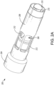
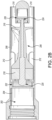
- FIG. 2A depicts a perspective view of an illustrative percutaneous mechanical circulatory support device 200, in accordance with embodiments of the subject matter disclosed herein; and FIG. 2B depicts a cross-sectional side view of the circulatory support device 200 depicted in FIG. 2A , in accordance with embodiments of the subject matter disclosed herein.
- the circulatory support device 200 and/or any number of various components thereof, may be the same as, or similar to, corresponding components of the circulatory support device 100 depicted in FIGS. 1A and 1 B .
- the circulatory support device 200 includes a motor 202 disposed within a motor housing 204.
- the motor 202 is configured to drive an impeller assembly 206 to provide a flow of blood through the device 200.
- the impeller assembly 206 is disposed within an impeller assembly housing 208, which includes a number of inlet apertures 210 and a number of outlet apertures 1 12 defined therein.
- the motor housing 204 and the impeller assembly housing 208 may be integrated with one another. In other embodiments, the motor housing 204 and the impeller assembly housing 208 may be separate components configured to be coupled together, either removeably or permanently.
- a controller (not shown) is operably coupled to the motor 202 and is configured to control the motor 202.
- the controller may be disposed within the motor housing 204 in embodiments, or, in other embodiments, may be disposed outside the housing 204 (e.g., in a catheter handle, independent housing, etc.). In embodiments, the controller may include multiple components, one or more of which may be disposed within the housing 204. According to embodiments, the motor 204 may be, be similar to, include, or be included in the motor 104 depicted in FIG. 1A .
- the impeller assembly 206 includes a drive shaft 214 and an impeller 216 coupled thereto, where the drive shaft 214 is configured to rotate with the impeller 216.
- the drive shaft 214 is at least partially disposed within the impeller 216.
- the drive shaft 214 may be made of any number of different rigid materials such as, for example, steel, titanium alloys, cobalt chromium alloys, nitinol, high-strength ceramics, and/or the like.
- the impeller assembly 206 further includes an impeller rotor 218 coupled to, and at least partially surrounding, the drive shaft 214.
- the impeller rotor 218 may be any type of magnetic rotor capable of being driven by a stator (not shown, but which may be the same as, or similar to, the stator 118 depicted in FIGS. 1A and 1 B ) that is part of the motor 202. In this manner, as a magnetic field is applied to the impeller rotor 218 by the stator in the motor 202, the rotor 218 rotates, causing the drive shaft 214 and impeller 216 to rotate.
- the impeller assembly is maintained in its orientation by the drive shaft 214, which is retained, at a first end 220, by a first bearing assembly 222 and, at a second end 224, by a second bearing assembly 226.
- the first bearing assembly 222 and the second bearing assembly 226 may include different types of bearings.
- the first bearing assembly 222 and/or the second bearing assembly 226 include a lubricant chamber configured to hold a lubricant.
- Various embodiments of bearing technology are described herein with respect to the first and second bearing assemblies 222 and 226.
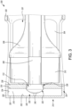
- FIG. 2C is a close-up view of the first bearing assembly 222 of FIG. 2B , in accordance with embodiments of the subject matter disclosed herein.
- the second bearing assembly 226 may include, for example, a journal bearing, or any other type of suitable bearing.
- the first bearing assembly 222 includes a bearing 228 having a first side 230, facing toward the impeller assembly 206, and an opposite, second side 232, facing toward the motor 202.
- a concave depression 234 is defined in the first side 230 of the bearing 228.
- the concave depression 234 is configured to receive the first end 220 of the drive shaft 214.
- the first end 220 of the drive shaft 214 is at least partially rounded and, in embodiments, the concave depression 234 may be sized to just fit the first end 22 of the drive shaft 214.
- the concave depression 234 may include a first portion 236 and a second portion 238 , where the first portion 236 has an at least approximately cylindrical shape and extends into the bearing 228 from the first side 230 of the bearing 228.
- the second portion 238 has an at least approximately concave shape.
- the first portion 236 may be sized to fit a corresponding first portion 240 of the first end 220 of the drive shaft 214, while the second portion 238 may be sized to fit a corresponding second portion 242 of the first end 220 of the drive shaft 214.
- the first portion 240 of the first end 220 of the drive shaft 214 may have an approximately cylindrical shape, and the second portion 242 of the first end 220 of the drive shaft 214 may have an approximately convex shape. In this manner, the first portion 238 of the depression 234 may facilitate maintaining the drive shaft 214 in its orientation.
- the concave geometry of the depression in conjunction with the rounded end of the drive shaft, creates a relatively large bearing surface, thereby distributing axial load over more area.
- the diameter of the end of the drive shaft (and, thus, of the concave depression) may be configured to facilitate desired performance characteristics. For example, increasing these diameters may lead to higher velocity of rotation, while reducing axial stresses, thereby reducing friction.
- the dimensions of the various aspects of the bearing assembly may be selected based on implementation, performance, materials, and/or the like.
- the first bearing assembly 222 may also include a biasing feature (not shown) disposed between the second side 232 of the bearing 228 and the motor 202.
- the biasing feature may have a compliance configured such that the biasing feature biases the bearing 228 in the direction of the drive shaft 214, resisting the load generated by the attraction between the impeller rotor 218 and the stator, while allowing enough flexibility to prevent the bearing 228 from being cracked or otherwise broken by the load.
- the bearing 228 may also, as shown, be retained in place by a bearing support feature 244, which may be integrated into the motor housing 204, the impeller assembly housing 208, or which may be a separate feature coupled to the motor housing 204 and/or the impeller assembly housing 208.
- the bearing support feature 244 may include any number of different types of features configured to maintain the bearing 228 in its position.
- the bearing support feature 244 may include multiple edges, a notch configured to receive a tab or edge, edges configured to form an interference fit with the periphery of the bearing, and/or the like.
- the bearing assembly 222 also includes a cup washer 246 having a base 248 and a peripheral wall 250 extending away from the base 248 towards the motor 202, forming a cavity 252 bounded by an inner surface 254 of the base 248 and an inner surface 256 of the peripheral wall 250.
- the peripheral wall 250 may be oriented approximately orthogonal to the base 248.
- a shaft aperture 258 is defined through the base 248, extending from an outer surface 260 of the base 248 to the inner surface 254 of the base 248, and is configured to receive a portion of the drive shaft 214.
- the bearing 228 is configured to be at least partially disposed within the cavity 252.
- a lubricant may be disposed within the cavity to facilitate preservation of the bearing 228 and its interface with the drive shaft 214. That is, at least a portion of a lubricant chamber is defined between the inner surface 254 of the base 248 of the cup washer 246, the inner surface 256 of the peripheral wall 250 of the cup washer 246, and the first side 230 of the bearing 228. Additionally or alternatively, a portion of a lubricant chamber may be defined within the bearing (e.g., within the bearing 228).
- the lubricant is any type of hydrophobic lubricant suitable for use in a blood pump.
- the lubricant may be a modified silicone lubricant such as, for example, a modified Polydimethylsiloxane (PDMS).
- the lubricant may be an oil-based lubricant, a synthetic oil, a carbon-based lubricant, and/or the like.
- the illustrative circulatory support device 200 shown in FIGS. 2A - 2C is not intended to suggest any limitation as to the scope of use or functionality of embodiments of the present disclosure.
- the illustrative circulatory support device 200 also should not be interpreted as having any dependency or requirement related to any single component or combination of components illustrated therein.
- various components depicted in FIGS. 2A - 2C may be, in embodiments, integrated with various ones of the other components depicted therein (and/or components not illustrated), all of which are considered to be within the ambit of the present disclosure.
- FIG. 3 depicts a cross-sectional side view of an illustrative circulatory support device 300 having an impeller assembly 301.
- the circulatory support device 300 and/or any number of various components thereof, may be the same as, or similar to, corresponding components of the circulatory support device 100 depicted in FIGS. 1A and 1 B , and/or the circulatory support device 200 depicted in FIGS. 2A - 2C .
- the impeller assembly 301 is disposed within an impeller assembly housing 302, which includes a number of outlet apertures 304 defined therein.
- the impeller assembly 301 includes a drive shaft 306 and an impeller 308 coupled thereto, where the drive shaft 306 is configured to rotate with the impeller 308.
- the drive shaft 306 is at least partially disposed within the impeller 308.
- the drive shaft 306 may be made of any number of different rigid materials such as, for example, steel, titanium alloys, cobalt chromium alloys, nitinol, high-strength ceramics, and/or the like.
- the impeller assembly 308 further includes an impeller rotor 310 coupled to, and at least partially surrounding, the drive shaft 306.
- the impeller rotor 310 may be any type of magnetic rotor capable of being driven by a stator (not shown, but which may be the same as, or similar to, the stator 118 depicted in FIGS. 1A and 1 B ) that is part of the motor. In this manner, as a magnetic field is applied to the impeller rotor 310 by the stator in the motor, the rotor 310 rotates, causing the drive shaft 306 and impeller 308 to rotate.
- the impeller assembly 301 is maintained in its orientation by the drive shaft 306, which is retained, at a first end 312, by a first bearing assembly 314 and, at a second end (not shown), by a second bearing assembly (not shown).
- the first bearing assembly 314 and the second bearing assembly may include different types of bearings.
- the first bearing assembly 314 and/or the second bearing assembly may include a lubricant chamber configured to hold a lubricant.
- the first bearing assembly 314 includes a bearing 316 having a first side 318, facing toward the impeller assembly 301 , and an opposite, second side 320, facing toward the motor.
- a concave depression 322 is defined in the first side 318 of the bearing 316.
- the concave depression 322 is configured to receive the first end 312 of the drive shaft 306 and may, in embodiments, be configured in a manner similar to the concave depression 134 depicted in FIG. 1 B and/or the concave depression 234 depicted in FIG. 2C .
- the first end 312 of the drive shaft 214 may configured similar to the first end 120 of the drive shaft 1 12 depicted in FIGS. 1A and 1 B and/or the first end 220 of the drive shaft 214 depicted in FIGS. 2B - 2C .
- the first bearing assembly 314 may also include a biasing feature (not shown) disposed between the second side 320 of the bearing 316 and the motor.
- the bearing assembly 314 also includes a cup washer 324 or other similar basin-like structure, having a base 326 and a peripheral wall 328 extending away from the base 326 toward the impeller assembly 301, forming a cavity 330 bounded by an inner surface 332 of the base 326 and an inner surface 334 of the peripheral wall 328.
- the bearing 316 is configured to be at least partially disposed within the cavity 330.
- a cover 336 may be disposed adjacent to the first side 318 of the bearing 316, and include a shaft aperture 338 configured to receive a portion of the drive shaft 306.
- the cover 336 may be a layer of graphite, a polymer, and/or the like.
- the bearing assembly 314 includes a lubricant chamber configured to retain a lubricant.
- the lubricant chamber may include at least one channel 340 defined in the second side 320 of the bearing 316.
- the channel or channels pass through the depression 322.
- the bearing 316 may include two or more channels 340 defined therein.
- at least a portion of the inner surface 332 of the base 326 may form a boundary of the lubricant chamber.
- the illustrative circulatory support device 300 shown in FIG. 3 is not intended to suggest any limitation as to the scope of use or functionality of embodiments of the present disclosure.
- the illustrative circulatory support device 300 also should not be interpreted as having any dependency or requirement related to any single component or combination of components illustrated therein.
- various components depicted in FIG. 3 may be, in embodiments, integrated with various ones of the other components depicted therein (and/or components not illustrated), all of which are considered to be within the ambit of the present disclosure.
- FIG. 4 depicts a cross-sectional side view of an illustrative circulatory support device 400 having an impeller assembly 402, in accordance with embodiments of the subject matter disclosed herein.
- the circulatory support device 400 and/or any number of various components thereof, may be the same as, or similar to, corresponding components of the circulatory support device 100 depicted in FIGS. 1A and 1 B , the circulatory support device 200 depicted in FIGS. 2A - 2C , and/or the circulatory support device 300 depicted in FIG. 3 .
- the portion of the circulatory support device 400 depicted in FIG. 4 is the portion of an impeller assembly associated with an end opposite the end adjacent the motor.
- the bearing assembly 404 depicted in FIG. 4 may be, be similar to, and/or otherwise correspond to the bearing assembly 126 depicted in FIG. 1A and/or the bearing assembly 226 depicted in FIG. 2B .
- implementations of the bearing assembly 404 may be used, alternatively or additionally, as the bearing assembly 122 depicted in FIGS. 1A and 1 B , the bearing assembly 222 depicted in FIGS. 2B and 2C , the bearing assembly 314 depicted in FIG. 3 , and/or the like.
- the impeller assembly 402 is disposed within an impeller assembly housing 406, which includes a number of apertures (not shown) defined therein.
- the impeller assembly 402 includes a drive shaft 408 and an impeller 410 coupled thereto, where the drive shaft 408 is configured to rotate with the impeller 410.
- the drive shaft 408 is at least partially disposed within the impeller 410.
- the drive shaft 408 may be made of any number of different rigid materials such as, for example, steel, titanium alloys, cobalt chromium alloys, nitinol, high-strength ceramics, and/or the like.
- the impeller assembly 402 is maintained in its orientation by the drive shaft 408, which is retained, at a first end (not shown), by a first bearing assembly (not shown) and, at a second end 412, by the bearing assembly.
- the first bearing assembly and the second bearing assembly 404 may include different types of bearings.
- the first bearing assembly and/or the second bearing assembly 404 may include a lubricant chamber configured to hold a lubricant.
- the bearing assembly 404 includes a cylindrical-shaped bearing 414 disposed in the end 412 of the drive shaft 408.
- the bearing 414 includes a first inside surface 416 facing away from the impeller and a second inside surface 418 extending away from the first inside surface.
- the second inside surface 418 may be oriented approximately orthogonal to the first inside surface 416.
- cylindrical-shaped bearing is disposed at an intersection of the drive shaft 408 and a stationary shaft mounting pin 420.
- the shaft mounting pin may be made of any number of different materials.
- the shaft mounting pin 420 may be made of the same material as the drive shaft 408.
- the shaft mounting pin 420 may be coupled to a pin support 422.
- the drive shaft 408 is configured to rotate with respect to the stationary shaft mounting pin 420.
- the bearing assembly 404 includes a lubricant chamber 424.
- the lubricant chamber 424 may be defined between the first inner surface 416 of the bearing 414 and an outer surface 426 of the stationary shaft mounting pin 420.
- the lubricant chamber 424 may be further bounded by at least a portion of the second inner surface 418 of the bearing 414.
- the illustrative circulatory support device 400 shown in FIG. 4 is not intended to suggest any limitation as to the scope of use or functionality of embodiments of the present disclosure.
- the illustrative circulatory support device 400 also should not be interpreted as having any dependency or requirement related to any single component or combination of components illustrated therein.
- various components depicted in FIG. 4 may be, in embodiments, integrated with various ones of the other components depicted therein (and/or components not illustrated), all of which are considered to be within the ambit of the present disclosure.
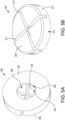
- FIGS. 5A and 5B are perspective views of an illustrative bearing 500.
- the bearing 500 may be, or be similar to, the bearing 122 depicted in FIGS. 1A and 1 B , the bearing 222 depicted in FIGS. 2A - 2C , the bearing 322 depicted in FIG. 3 , and/or the like.
- the bearing 500 includes a first side 502, configured to face toward an impeller assembly, and an opposite, second side 504, configured to face toward a motor.
- a concave depression 506 is defined in the first side 230 of the bearing 500.
- the concave depression 506 is configured to receive an end of a drive shaft.
- the end of the drive shaft may be at least partially rounded and, in embodiments, the concave depression 506 may be sized to just fit the end of the drive shaft.
- the concave depression 500 may include a first portion 508 and a second portion 510, where the first portion 508 has an at least approximately cylindrical shape and extends into the bearing 500 from the first side 502 of the bearing 500.
- the second portion 510 has an at least approximately concave shape.
- the first portion 508 may be sized to fit a corresponding first portion of the end of the drive shaft, while the second portion 510 may be sized to fit a corresponding second portion of the end of the drive shaft.
- the first portion of the end of the drive shaft may have an approximately cylindrical shape, and the second portion of the end of the drive shaft may have an approximately convex shape. In this manner, the first portion 508 of the depression 506 may facilitate maintaining the drive shaft in its orientation.
- the bearing 500 may include any number of channels (e.g., 1, 2, 3, 4, 5, etc.) having any number of different depths, widths, and/or the like. In embodiments, for example, the channels do not extend through the outside surface 514 of the periphery wall 516. In embodiments, the bearing 500 may include multiple channels of varying size. For example, the bearing 500 may include microchannels (e.g., channels that are substantially narrower and shallower than the channels 512 such as, for example, by at least a factor of 5) defined in an upper surface 518 of the concave depression. According to embodiments, using bearings with channels defined therein for lubricant chambers may facilitate using thinner bearings, thereby enabling the rotor of the impeller assembly to be closer to the stator of the motor, which may enable increased torque and efficiency.
- microchannels e.g., channels that are substantially narrower and shallower than the channels 512 such as, for example, by at least a factor of 5
- the bearing 500 shown in FIGS. 5A and 5B is not intended to suggest any limitation as to the scope of use or functionality of embodiments of the present disclosure.
- the illustrative bearing 500 also should not be interpreted as having any dependency or requirement related to any single component or combination of components illustrated therein.
- various components depicted in FIGS. 5A and 5B may be, in embodiments, integrated with various ones of the other components depicted therein (and/or components not illustrated), all of which are considered to be within the ambit of the present disclosure.
Landscapes
- Engineering & Computer Science (AREA)
- Health & Medical Sciences (AREA)
- Heart & Thoracic Surgery (AREA)
- Mechanical Engineering (AREA)
- General Engineering & Computer Science (AREA)
- General Health & Medical Sciences (AREA)
- Biomedical Technology (AREA)
- Hematology (AREA)
- Life Sciences & Earth Sciences (AREA)
- Animal Behavior & Ethology (AREA)
- Anesthesiology (AREA)
- Public Health (AREA)
- Veterinary Medicine (AREA)
- Cardiology (AREA)
- Chemical & Material Sciences (AREA)
- Oil, Petroleum & Natural Gas (AREA)
- Physics & Mathematics (AREA)
- Fluid Mechanics (AREA)
- Vascular Medicine (AREA)
- External Artificial Organs (AREA)
- Structures Of Non-Positive Displacement Pumps (AREA)
- Sliding-Contact Bearings (AREA)
Claims (3)
- Blutpumpe (200; 400), umfassend:
einen Impeller (216; 410):eine Antriebswelle (214; 408), die mit dem Impeller (216; 410) gekoppelt und dazu ausgelegt ist, mit dem Impeller (216; 410) zu drehen;einen Motor (202), der dazu ausgelegt ist, den Impeller (216; 410) anzutreiben; undeine Lageranordnung (222; 404), die dazu ausgelegt ist, ein Ende (220) der Antriebswelle (214; 408) zu halten; wobei die Lageranordnung (222; 404) umfasst:ein Lager (228), wobei das Ende (220) der Antriebswelle (214) mindestens teilweise abgerundet ist, und wobei das Lager eine konkave Vertiefung (234) umfasst, die in einer ersten Seite (230) des Lagers definiert ist, wobei die Vertiefung (234) dazu ausgelegt ist, das Ende (220) der Antriebswelle (214) aufzunehmen; undeine Schmiermittelkammer, die ein hydrophobes Schmiermittel enthält,dadurch gekennzeichnet, dass die Lageranordnung (222) ferner eine Tellerscheibe (246) mit einer Basis (248) und einer Umfangswand (250) umfasst, die sich von der Basis (248) weg erstreckt, die einen Hohlraum (252) bildet, der von einer Innenseite (256) der Umfangswand (250) und einer Innenseite (254) der Basis (248) begrenzt ist, wobei das Lager dazu ausgelegt ist, mindestens teilweise innerhalb des Hohlraums (252) angeordnet zu werden, unddadurch, dass die Tellerscheibe (246) ferner eine Wellenöffnung (258) umfasst, die in der Basis (248) definiert ist und sich von der Außenseite (260) der Basis (248) zur Innenseite (254) der Basis (248) erstreckt, wobei die Wellenöffnung (258) dazu ausgelegt ist, einen Abschnitt der Antriebswelle (214; 306) aufzunehmen, unddadurch, dass mindestens ein Abschnitt der Schmiermittelkammer zwischen der Innenseite (256) der Umfangswand (250) der Tellerscheibe (246), der Innenseite (254) der Basis (248) der Tellerscheibe (246) und der ersten Seite (230) des Lagers definiert ist. - Blutpumpe nach Anspruch 1, wobei die Lageranordnung (222) neben dem Motor (202) angeordnet ist.
- Blutpumpe nach einem der vorhergehenden Ansprüche, wobei das Ende (220) ein erstes Ende ist und wobei die Lageranordnung (404) ein zylindrisch geformtes Lager (414) ist, das in einem zweiten Ende (412) der Antriebswelle (408) an einem Schnittpunkt der Antriebswelle (408) und einem ortsfesten Wellenmontagestift (420) angeordnet ist, wobei die Antriebswelle (408) dazu ausgelegt ist, mit Bezug auf den ortsfesten Wellenmontagestift (420) zu drehen, und wobei eine weitere Schmiermittelkammer (424) zwischen einer Innenseite (416) des Lagers (414) und einer Außenseite (426) des ortsfesten Wellenmontagestifts (420) definiert ist.
Applications Claiming Priority (2)
| Application Number | Priority Date | Filing Date | Title |
|---|---|---|---|
| US201862747346P | 2018-10-18 | 2018-10-18 | |
| PCT/US2019/056956 WO2020081944A1 (en) | 2018-10-18 | 2019-10-18 | Blood pump shaft bearing |
Publications (2)
| Publication Number | Publication Date |
|---|---|
| EP3867541A1 EP3867541A1 (de) | 2021-08-25 |
| EP3867541B1 true EP3867541B1 (de) | 2025-01-08 |
Family
ID=68468849
Family Applications (1)
| Application Number | Title | Priority Date | Filing Date |
|---|---|---|---|
| EP19798470.1A Active EP3867541B1 (de) | 2018-10-18 | 2019-10-18 | Blutpumpe |
Country Status (4)
| Country | Link |
|---|---|
| US (3) | US11565103B2 (de) |
| EP (1) | EP3867541B1 (de) |
| CN (2) | CN116804421A (de) |
| WO (1) | WO2020081944A1 (de) |
Families Citing this family (50)
| Publication number | Priority date | Publication date | Assignee | Title |
|---|---|---|---|---|
| EP4290081A3 (de) | 2015-09-25 | 2024-02-21 | Procyrion, Inc. | Okklusionsfreie intravaskulare blutpumpe mit reduzierter hämolyse |
| EP4732889A2 (de) | 2017-06-07 | 2026-04-29 | Supira Medical, Inc. | Vorrichtungen, systeme und verfahren zur bewegung intravaskulärer flüssigkeiten |
| DE102018201030B4 (de) | 2018-01-24 | 2025-10-16 | Kardion Gmbh | Magnetkuppelelement mit magnetischer Lagerungsfunktion |
| EP4085965A1 (de) | 2018-02-01 | 2022-11-09 | Shifamed Holdings, LLC | Intravaskuläre blutpumpen und verfahren zur verwendung und herstellung |
| DE102018207594A1 (de) | 2018-05-16 | 2019-11-21 | Kardion Gmbh | Rotor, Magnetkupplungsvorrichtung, Elektromotor für ein Herzunterstützungssystem, Pumpeneinheit für ein Herzunterstützungssystem sowie Verfahren zum Herstellen eines Rotors |
| DE102018207575A1 (de) | 2018-05-16 | 2019-11-21 | Kardion Gmbh | Magnetische Stirndreh-Kupplung zur Übertragung von Drehmomenten |
| DE102018207611A1 (de) | 2018-05-16 | 2019-11-21 | Kardion Gmbh | Rotorlagerungssystem |
| DE102018208539A1 (de) | 2018-05-30 | 2019-12-05 | Kardion Gmbh | Motorgehäusemodul zum Abdichten eines Motorraums eines Motors eines Herzunterstützungssystems und Herzunterstützungssystem und Verfahren zum Montieren eines Herzunterstützungssystems |
| DE102018208541A1 (de) | 2018-05-30 | 2019-12-05 | Kardion Gmbh | Axialpumpe für ein Herzunterstützungssystem und Verfahren zum Herstellen einer Axialpumpe für ein Herzunterstützungssystem |
| DE102018208549A1 (de) | 2018-05-30 | 2019-12-05 | Kardion Gmbh | Elektronikmodul für ein Herzunterstützungssystem und Verfahren zum Herstellen eines Elektronikmoduls für ein Herzunterstützungssystem |
| DE102018208538A1 (de) | 2018-05-30 | 2019-12-05 | Kardion Gmbh | Intravasale Blutpumpe und Verfahren zur Herstellung von elektrischen Leiterbahnen |
| DE102018208550A1 (de) | 2018-05-30 | 2019-12-05 | Kardion Gmbh | Leitungsvorrichtung zum Leiten eines Blutstroms für ein Herzunterstützungssystem, Herzunterstützungssystem und Verfahren zum Herstellen einer Leitungsvorrichtung |
| DE102018210076A1 (de) | 2018-06-21 | 2019-12-24 | Kardion Gmbh | Verfahren und Vorrichtung zum Erkennen eines Verschleißzustands eines Herzunterstützungssystems, Verfahren und Vorrichtung zum Betreiben eines Herzunterstützungssystems und Herzunterstützungssystem |
| DE102018210058A1 (de) | 2018-06-21 | 2019-12-24 | Kardion Gmbh | Statorschaufelvorrichtung zur Strömungsführung eines aus einer Austrittsöffnung eines Herzunterstützungssystems ausströmenden Fluids, Herzunterstützungssystem mit Statorschaufelvorrichtung, Verfahren zum Betreiben einer Statorschaufelvorrichtung und Herstellverfahren |
| DE102018211297A1 (de) | 2018-07-09 | 2020-01-09 | Kardion Gmbh | Herzunterstützungssystem und Verfahren zur Überwachung der Integrität einer Haltestruktur eines Herzunterstützungssystems |
| DE102018211327A1 (de) | 2018-07-10 | 2020-01-16 | Kardion Gmbh | Laufrad für ein implantierbares, vaskuläres Unterstützungssystem |
| DE102018211328A1 (de) | 2018-07-10 | 2020-01-16 | Kardion Gmbh | Laufradgehäuse für ein implantierbares, vaskuläres Unterstützungssystem |
| DE102018212153A1 (de) | 2018-07-20 | 2020-01-23 | Kardion Gmbh | Zulaufleitung für eine Pumpeneinheit eines Herzunterstützungssystems, Herzunterstützungssystem und Verfahren zum Herstellen einer Zulaufleitung für eine Pumpeneinheit eines Herzunterstützungssystems |
| EP3833410B1 (de) | 2018-08-07 | 2025-10-08 | Kardion GmbH | Lagervorrichtung für ein herzunterstützungssystem und verfahren zum spülen eines zwischenraums in einer lagervorrichtung für ein herzunterstützungssystem |
| CN116804421A (zh) | 2018-10-18 | 2023-09-26 | 波士顿科学国际有限公司 | 血泵轴轴承 |
| JP7216206B2 (ja) * | 2019-03-25 | 2023-01-31 | ボストン サイエンティフィック サイムド,インコーポレイテッド | 腐食防止機構付き機械的循環補助ポンプドライブ |
| EP3996797A4 (de) | 2019-07-12 | 2023-08-02 | Shifamed Holdings, LLC | Intravaskuläre blutpumpen und verfahren zur herstellung und verwendung |
| EP4010046A4 (de) | 2019-08-07 | 2023-08-30 | Calomeni, Michael | Katheterblutpumpen und zusammenklappbare pumpengehäuse |
| US12171994B2 (en) | 2019-09-11 | 2024-12-24 | Boston Scientific Scimed, Inc. | Reduced thrombosis blood pump with washout bearing |
| US11577067B2 (en) * | 2019-10-03 | 2023-02-14 | Boston Scientific Scimed, Inc. | Reduced thrombosis blood pump |
| IL293625A (en) | 2019-12-03 | 2022-08-01 | Procyrion Inc | blood pumps |
| EP4072650A4 (de) | 2019-12-11 | 2024-01-10 | Shifamed Holdings, LLC | Absteigende aorten- und hohlvenenblutpumpen |
| JP7725472B2 (ja) | 2019-12-13 | 2025-08-19 | プロシリオン インコーポレイテッド | 血管内血液ポンプの支持構造 |
| WO2021127503A1 (en) | 2019-12-19 | 2021-06-24 | Shifamed Holdings, Llc | Intravascular blood pumps, motors, and fluid control |
| DE102020102474A1 (de) | 2020-01-31 | 2021-08-05 | Kardion Gmbh | Pumpe zum Fördern eines Fluids und Verfahren zum Herstellen einer Pumpe |
| EP3884969A1 (de) * | 2020-03-27 | 2021-09-29 | Abiomed Europe GmbH | Blutpumpe |
| NL2025395B1 (en) * | 2020-04-22 | 2021-10-28 | P Bekkers Holding B V | High pressure nozzle |
| US12589234B2 (en) | 2020-05-29 | 2026-03-31 | Supira Medical, Inc. | Intravascular blood pumps |
| CN119327026B (zh) * | 2020-07-31 | 2025-10-31 | 深圳核心医疗科技股份有限公司 | 介入式心室辅助装置 |
| AU2021340802A1 (en) | 2020-09-14 | 2023-05-18 | Kardion Gmbh | Cardiovascular support pump having an impeller with a variable flow area |
| AU2021383931A1 (en) | 2020-11-20 | 2023-07-06 | Kardion Gmbh | Mechanical circulatory support system with guidewire aid |
| EP4259266A1 (de) | 2021-02-10 | 2023-10-18 | Boston Scientific Scimed Inc. | Magnetischer antrieb und lager für eine hämodynamische unterstützungspumpe |
| WO2023091452A1 (en) * | 2021-11-16 | 2023-05-25 | Boston Scientific Scimed Inc. | Percutaneous circulatory support system facilitating reduced hemolysis |
| CN114796849B (zh) * | 2022-02-23 | 2026-01-02 | 深圳核心医疗科技股份有限公司 | 血泵及其驱动装置 |
| CN116808430A (zh) * | 2022-07-08 | 2023-09-29 | 深圳核心医疗科技股份有限公司 | 驱动装置和血泵 |
| CN115068811B (zh) * | 2022-07-08 | 2026-01-02 | 深圳核心医疗科技股份有限公司 | 驱动装置和血泵 |
| WO2024007813A1 (zh) * | 2022-07-08 | 2024-01-11 | 深圳核心医疗科技股份有限公司 | 驱动机构和血泵 |
| CN115282467B (zh) * | 2022-07-08 | 2024-02-23 | 深圳核心医疗科技股份有限公司 | 驱动机构和血泵 |
| CN115006717B (zh) * | 2022-07-08 | 2026-01-02 | 深圳核心医疗科技股份有限公司 | 驱动装置和血泵 |
| CN115025387B (zh) | 2022-07-08 | 2023-05-30 | 深圳核心医疗科技股份有限公司 | 驱动装置和血泵 |
| CN115300786A (zh) * | 2022-07-26 | 2022-11-08 | 深圳核心医疗科技有限公司 | 驱动装置和血泵 |
| CN117282020A (zh) * | 2022-08-15 | 2023-12-26 | 深圳核心医疗科技股份有限公司 | 驱动装置和血泵 |
| CN115364366B (zh) * | 2022-08-30 | 2026-03-27 | 深圳核心医疗科技股份有限公司 | 驱动机构和血泵 |
| CN115253063A (zh) * | 2022-09-02 | 2022-11-01 | 深圳核心医疗科技有限公司 | 驱动机构和血泵 |
| CN115382092A (zh) * | 2022-09-05 | 2022-11-25 | 深圳核心医疗科技有限公司 | 驱动装置和血泵 |
Citations (1)
| Publication number | Priority date | Publication date | Assignee | Title |
|---|---|---|---|---|
| DE69027525T2 (de) * | 1990-04-09 | 1997-01-16 | St. Jude Medical, Inc., St. Paul, Minn. | Zentrifugalblutpumpe und Motorantrieb |
Family Cites Families (45)
| Publication number | Priority date | Publication date | Assignee | Title |
|---|---|---|---|---|
| US3265452A (en) * | 1965-05-04 | 1966-08-09 | Mechanical Tech Inc | Bearings |
| GB2101695B (en) * | 1981-07-10 | 1985-03-06 | British Gas Corp | Improvements in or relating to lubricated bearings |
| US4817586A (en) | 1987-11-24 | 1989-04-04 | Nimbus Medical, Inc. | Percutaneous bloom pump with mixed-flow output |
| US4895557A (en) | 1987-12-07 | 1990-01-23 | Nimbus Medical, Inc. | Drive mechanism for powering intravascular blood pumps |
| US5017103A (en) * | 1989-03-06 | 1991-05-21 | St. Jude Medical, Inc. | Centrifugal blood pump and magnetic coupling |
| US5211546A (en) * | 1990-05-29 | 1993-05-18 | Nu-Tech Industries, Inc. | Axial flow blood pump with hydrodynamically suspended rotor |
| US7077822B1 (en) | 1994-02-09 | 2006-07-18 | The University Of Iowa Research Foundation | Stereotactic hypothalamic obesity probe |
| US5588812A (en) * | 1995-04-19 | 1996-12-31 | Nimbus, Inc. | Implantable electric axial-flow blood pump |
| US5568976A (en) * | 1995-12-04 | 1996-10-29 | J.C. Pardo & Sons | Idler bearing mount for mounting of inclined agitators |
| US6093001A (en) * | 1997-05-02 | 2000-07-25 | University Of Pittsburgh | Rotary pump having a bearing which dissipates heat |
| US6186665B1 (en) * | 1999-01-26 | 2001-02-13 | Nimbus, Inc. | Motor rotor bearing assembly for a blood pump |
| AUPP995999A0 (en) * | 1999-04-23 | 1999-05-20 | University Of Technology, Sydney | Non-contact estimation and control system |
| US20060155158A1 (en) | 2002-06-11 | 2006-07-13 | Aboul-Hosn Walid N | Percutaneously introduced blood pump and related methods |
| JP2005220777A (ja) * | 2004-02-04 | 2005-08-18 | Matsushita Electric Ind Co Ltd | ベーンロータリ型真空ポンプ |
| EP2438937B1 (de) | 2005-06-06 | 2015-10-28 | The Cleveland Clinic Foundation | Blutpumpe |
| US8672611B2 (en) * | 2006-01-13 | 2014-03-18 | Heartware, Inc. | Stabilizing drive for contactless rotary blood pump impeller |
| CA2646277C (en) | 2006-03-23 | 2016-01-12 | The Penn State Research Foundation | Heart assist device with expandable impeller pump |
| CN101015716A (zh) * | 2007-03-09 | 2007-08-15 | 清华大学 | 一种植入式无接触微型轴流血泵 |
| US8439859B2 (en) | 2007-10-08 | 2013-05-14 | Ais Gmbh Aachen Innovative Solutions | Catheter device |
| US8489190B2 (en) | 2007-10-08 | 2013-07-16 | Ais Gmbh Aachen Innovative Solutions | Catheter device |
| US9199020B2 (en) | 2007-11-01 | 2015-12-01 | Abiomed, Inc. | Purge-free miniature rotary pump |
| EP2246078A1 (de) | 2009-04-29 | 2010-11-03 | ECP Entwicklungsgesellschaft mbH | Wellenanordnung mit einer Welle, die innerhalb einer fluidgefüllten Hülle verläuft |
| WO2011003043A1 (en) | 2009-07-01 | 2011-01-06 | The Penn State Research Foundation | Blood pump with expandable cannula |
| US8597170B2 (en) | 2011-01-05 | 2013-12-03 | Thoratec Corporation | Catheter pump |
| WO2012094641A2 (en) | 2011-01-06 | 2012-07-12 | Thoratec Corporation | Percutaneous heart pump |
| US8591393B2 (en) | 2011-01-06 | 2013-11-26 | Thoratec Corporation | Catheter pump |
| US9162017B2 (en) | 2011-08-29 | 2015-10-20 | Minnetronix, Inc. | Expandable vascular pump |
| US8849398B2 (en) | 2011-08-29 | 2014-09-30 | Minnetronix, Inc. | Expandable blood pump for cardiac support |
| DE102012202411B4 (de) | 2012-02-16 | 2018-07-05 | Abiomed Europe Gmbh | Intravasale blutpumpe |
| DE102012203615B4 (de) | 2012-03-07 | 2013-11-21 | Hanning Elektro-Werke Gmbh & Co. Kg | Pumpe |
| US9144638B2 (en) * | 2013-03-14 | 2015-09-29 | Thoratec Corporation | Blood pump rotor bearings |
| US8777832B1 (en) | 2013-03-14 | 2014-07-15 | The University Of Kentucky Research Foundation | Axial-centrifugal flow catheter pump for cavopulmonary assistance |
| DE102013208038B4 (de) | 2013-05-02 | 2016-09-08 | Michael Siegenthaler | Katheterbasierendes Herzunterstützungssystem |
| US20160045654A1 (en) | 2014-08-14 | 2016-02-18 | Medibotics Llc | Implanted Extracardiac Device for Circulatory Assistance |
| EP2865397A1 (de) | 2013-10-22 | 2015-04-29 | Berlin Heart GmbH | Verfahren zum Betrieb einer Pumpeneinrichtung sowie Pumpeneinrichtung |
| US9308305B2 (en) | 2014-06-18 | 2016-04-12 | Ch Biomedical (Usa) Inc. | Implantable blood pump with integrated controller |
| US9345824B2 (en) | 2014-07-07 | 2016-05-24 | Assistocor Gmbh & Co Kg | Ventricular assist device |
| GB2535163B (en) * | 2015-02-09 | 2017-04-05 | Edwards Ltd | Pump lubricant supply systems |
| ES2986599T3 (es) * | 2015-03-18 | 2024-11-12 | Abiomed Europe Gmbh | Bomba de sangre |
| US9907890B2 (en) | 2015-04-16 | 2018-03-06 | Tc1 Llc | Catheter pump with positioning brace |
| DK3808404T3 (da) * | 2015-08-04 | 2025-05-19 | Abiomed Europe Gmbh | Blodpumpe med selvspulende leje |
| EP3222301B1 (de) | 2016-03-23 | 2018-05-09 | Abiomed Europe GmbH | Blutpumpe |
| CN107349484A (zh) * | 2017-08-24 | 2017-11-17 | 清华大学 | 悬浮转子血液泵和泵送系统 |
| CN207568879U (zh) * | 2017-09-21 | 2018-07-03 | 深圳核心医疗器械有限公司 | 一种快速验证血泵压力流量曲线的装置 |
| CN116804421A (zh) | 2018-10-18 | 2023-09-26 | 波士顿科学国际有限公司 | 血泵轴轴承 |
-
2019
- 2019-10-18 CN CN202310671702.1A patent/CN116804421A/zh active Pending
- 2019-10-18 WO PCT/US2019/056956 patent/WO2020081944A1/en not_active Ceased
- 2019-10-18 CN CN201980059651.9A patent/CN112689716B/zh active Active
- 2019-10-18 EP EP19798470.1A patent/EP3867541B1/de active Active
- 2019-10-18 US US16/657,246 patent/US11565103B2/en active Active
-
2023
- 2023-01-11 US US18/095,738 patent/US12290676B2/en active Active
-
2025
- 2025-04-07 US US19/171,672 patent/US20250229078A1/en active Pending
Patent Citations (1)
| Publication number | Priority date | Publication date | Assignee | Title |
|---|---|---|---|---|
| DE69027525T2 (de) * | 1990-04-09 | 1997-01-16 | St. Jude Medical, Inc., St. Paul, Minn. | Zentrifugalblutpumpe und Motorantrieb |
Also Published As
| Publication number | Publication date |
|---|---|
| US20200121835A1 (en) | 2020-04-23 |
| CN116804421A (zh) | 2023-09-26 |
| WO2020081944A1 (en) | 2020-04-23 |
| US20230158290A1 (en) | 2023-05-25 |
| US20250229078A1 (en) | 2025-07-17 |
| CN112689716B (zh) | 2023-06-30 |
| US11565103B2 (en) | 2023-01-31 |
| EP3867541A1 (de) | 2021-08-25 |
| CN112689716A (zh) | 2021-04-20 |
| US12290676B2 (en) | 2025-05-06 |
Similar Documents
| Publication | Publication Date | Title |
|---|---|---|
| EP3867541B1 (de) | Blutpumpe | |
| US11666748B2 (en) | Hybrid bearing seal for use in blood pump | |
| EP3986528B1 (de) | Blutpumpe mit reduzierter thrombose | |
| US12453849B2 (en) | Mechanical circulatory support pump drive with corrosion protection | |
| US12171994B2 (en) | Reduced thrombosis blood pump with washout bearing | |
| JP6507393B2 (ja) | すべり軸受及びポンプ | |
| CN106794293B (zh) | 心脏泵 | |
| US10722627B1 (en) | Blood pump bearing with integrated fluid diffuser/inducer system | |
| JPH11247844A (ja) | コンプライアント箔流体膜ラジアル軸受 | |
| EP2532897A1 (de) | Zentrifugalpumpe | |
| US11608832B2 (en) | Rotary drive for an impeller and motor assembly with gas and rolling bearings arranged in housing structure | |
| JP2018501431A (ja) | 真空ポンプ潤滑油供給システム | |
| US20140254966A1 (en) | Bearing with Axial Variation | |
| JP2007506059A (ja) | 玉軸受 | |
| JP7630907B2 (ja) | 向上した効率のジャーナル軸受 | |
| JP6706184B2 (ja) | コンプレッサ用斜板 | |
| JPS6288817A (ja) | スラストすべり軸受装置 | |
| JP2015203359A (ja) | 内接ギアポンプ | |
| JP2001090729A (ja) | 転動リングのすべり軸受 | |
| US20230095344A1 (en) | Rolling-element bearing | |
| KR20190129467A (ko) | 틸팅 패드 베어링 | |
| JP6706185B2 (ja) | コンプレッサ用斜板 | |
| JP2003090331A (ja) | 動圧流体軸受装置及びこれを用いたスピンドルモータ | |
| CN110103642A (zh) | 车辆用轴承装置 | |
| JPH09324767A (ja) | ポンプ |
Legal Events
| Date | Code | Title | Description |
|---|---|---|---|
| STAA | Information on the status of an ep patent application or granted ep patent |
Free format text: STATUS: UNKNOWN |
|
| STAA | Information on the status of an ep patent application or granted ep patent |
Free format text: STATUS: THE INTERNATIONAL PUBLICATION HAS BEEN MADE |
|
| PUAI | Public reference made under article 153(3) epc to a published international application that has entered the european phase |
Free format text: ORIGINAL CODE: 0009012 |
|
| STAA | Information on the status of an ep patent application or granted ep patent |
Free format text: STATUS: REQUEST FOR EXAMINATION WAS MADE |
|
| 17P | Request for examination filed |
Effective date: 20210417 |
|
| AK | Designated contracting states |
Kind code of ref document: A1 Designated state(s): AL AT BE BG CH CY CZ DE DK EE ES FI FR GB GR HR HU IE IS IT LI LT LU LV MC MK MT NL NO PL PT RO RS SE SI SK SM TR |
|
| DAV | Request for validation of the european patent (deleted) | ||
| DAX | Request for extension of the european patent (deleted) | ||
| STAA | Information on the status of an ep patent application or granted ep patent |
Free format text: STATUS: EXAMINATION IS IN PROGRESS |
|
| 17Q | First examination report despatched |
Effective date: 20221006 |
|
| REG | Reference to a national code |
Ref country code: DE Ref legal event code: R079 Free format text: PREVIOUS MAIN CLASS: F16C0017080000 Ipc: A61M0060130000 Ref country code: DE Ref legal event code: R079 Ref document number: 602019064662 Country of ref document: DE Free format text: PREVIOUS MAIN CLASS: F16C0017080000 Ipc: A61M0060130000 |
|
| RIC1 | Information provided on ipc code assigned before grant |
Ipc: A61M 60/13 20210101AFI20230626BHEP |
|
| RIC1 | Information provided on ipc code assigned before grant |
Ipc: F16C 17/08 20060101ALI20230705BHEP Ipc: F16C 33/10 20060101ALI20230705BHEP Ipc: A61M 60/13 20210101AFI20230705BHEP |
|
| GRAP | Despatch of communication of intention to grant a patent |
Free format text: ORIGINAL CODE: EPIDOSNIGR1 |
|
| STAA | Information on the status of an ep patent application or granted ep patent |
Free format text: STATUS: GRANT OF PATENT IS INTENDED |
|
| INTG | Intention to grant announced |
Effective date: 20240731 |
|
| GRAS | Grant fee paid |
Free format text: ORIGINAL CODE: EPIDOSNIGR3 |
|
| GRAA | (expected) grant |
Free format text: ORIGINAL CODE: 0009210 |
|
| STAA | Information on the status of an ep patent application or granted ep patent |
Free format text: STATUS: THE PATENT HAS BEEN GRANTED |
|
| AK | Designated contracting states |
Kind code of ref document: B1 Designated state(s): AL AT BE BG CH CY CZ DE DK EE ES FI FR GB GR HR HU IE IS IT LI LT LU LV MC MK MT NL NO PL PT RO RS SE SI SK SM TR |
|
| REG | Reference to a national code |
Ref country code: GB Ref legal event code: FG4D |
|
| REG | Reference to a national code |
Ref country code: CH Ref legal event code: EP |
|
| REG | Reference to a national code |
Ref country code: DE Ref legal event code: R096 Ref document number: 602019064662 Country of ref document: DE |
|
| REG | Reference to a national code |
Ref country code: IE Ref legal event code: FG4D |
|
| REG | Reference to a national code |
Ref country code: NL Ref legal event code: FP |
|
| REG | Reference to a national code |
Ref country code: LT Ref legal event code: MG9D |
|
| REG | Reference to a national code |
Ref country code: AT Ref legal event code: MK05 Ref document number: 1757950 Country of ref document: AT Kind code of ref document: T Effective date: 20250108 |
|
| PG25 | Lapsed in a contracting state [announced via postgrant information from national office to epo] |
Ref country code: RS Free format text: LAPSE BECAUSE OF FAILURE TO SUBMIT A TRANSLATION OF THE DESCRIPTION OR TO PAY THE FEE WITHIN THE PRESCRIBED TIME-LIMIT Effective date: 20250408 |
|
| PG25 | Lapsed in a contracting state [announced via postgrant information from national office to epo] |
Ref country code: FI Free format text: LAPSE BECAUSE OF FAILURE TO SUBMIT A TRANSLATION OF THE DESCRIPTION OR TO PAY THE FEE WITHIN THE PRESCRIBED TIME-LIMIT Effective date: 20250108 |
|
| PG25 | Lapsed in a contracting state [announced via postgrant information from national office to epo] |
Ref country code: PL Free format text: LAPSE BECAUSE OF FAILURE TO SUBMIT A TRANSLATION OF THE DESCRIPTION OR TO PAY THE FEE WITHIN THE PRESCRIBED TIME-LIMIT Effective date: 20250108 |
|
| PG25 | Lapsed in a contracting state [announced via postgrant information from national office to epo] |
Ref country code: ES Free format text: LAPSE BECAUSE OF FAILURE TO SUBMIT A TRANSLATION OF THE DESCRIPTION OR TO PAY THE FEE WITHIN THE PRESCRIBED TIME-LIMIT Effective date: 20250108 |
|
| PG25 | Lapsed in a contracting state [announced via postgrant information from national office to epo] |
Ref country code: NO Free format text: LAPSE BECAUSE OF FAILURE TO SUBMIT A TRANSLATION OF THE DESCRIPTION OR TO PAY THE FEE WITHIN THE PRESCRIBED TIME-LIMIT Effective date: 20250408 Ref country code: IS Free format text: LAPSE BECAUSE OF FAILURE TO SUBMIT A TRANSLATION OF THE DESCRIPTION OR TO PAY THE FEE WITHIN THE PRESCRIBED TIME-LIMIT Effective date: 20250508 |
|
| PG25 | Lapsed in a contracting state [announced via postgrant information from national office to epo] |
Ref country code: HR Free format text: LAPSE BECAUSE OF FAILURE TO SUBMIT A TRANSLATION OF THE DESCRIPTION OR TO PAY THE FEE WITHIN THE PRESCRIBED TIME-LIMIT Effective date: 20250108 |
|
| PG25 | Lapsed in a contracting state [announced via postgrant information from national office to epo] |
Ref country code: LV Free format text: LAPSE BECAUSE OF FAILURE TO SUBMIT A TRANSLATION OF THE DESCRIPTION OR TO PAY THE FEE WITHIN THE PRESCRIBED TIME-LIMIT Effective date: 20250108 Ref country code: PT Free format text: LAPSE BECAUSE OF FAILURE TO SUBMIT A TRANSLATION OF THE DESCRIPTION OR TO PAY THE FEE WITHIN THE PRESCRIBED TIME-LIMIT Effective date: 20250508 |
|
| PG25 | Lapsed in a contracting state [announced via postgrant information from national office to epo] |
Ref country code: BG Free format text: LAPSE BECAUSE OF FAILURE TO SUBMIT A TRANSLATION OF THE DESCRIPTION OR TO PAY THE FEE WITHIN THE PRESCRIBED TIME-LIMIT Effective date: 20250108 |
|
| PG25 | Lapsed in a contracting state [announced via postgrant information from national office to epo] |
Ref country code: AT Free format text: LAPSE BECAUSE OF FAILURE TO SUBMIT A TRANSLATION OF THE DESCRIPTION OR TO PAY THE FEE WITHIN THE PRESCRIBED TIME-LIMIT Effective date: 20250108 |
|
| PG25 | Lapsed in a contracting state [announced via postgrant information from national office to epo] |
Ref country code: SE Free format text: LAPSE BECAUSE OF FAILURE TO SUBMIT A TRANSLATION OF THE DESCRIPTION OR TO PAY THE FEE WITHIN THE PRESCRIBED TIME-LIMIT Effective date: 20250108 |
|
| PG25 | Lapsed in a contracting state [announced via postgrant information from national office to epo] |
Ref country code: SM Free format text: LAPSE BECAUSE OF FAILURE TO SUBMIT A TRANSLATION OF THE DESCRIPTION OR TO PAY THE FEE WITHIN THE PRESCRIBED TIME-LIMIT Effective date: 20250108 |
|
| REG | Reference to a national code |
Ref country code: DE Ref legal event code: R097 Ref document number: 602019064662 Country of ref document: DE |
|
| PG25 | Lapsed in a contracting state [announced via postgrant information from national office to epo] |
Ref country code: DK Free format text: LAPSE BECAUSE OF FAILURE TO SUBMIT A TRANSLATION OF THE DESCRIPTION OR TO PAY THE FEE WITHIN THE PRESCRIBED TIME-LIMIT Effective date: 20250108 |
|
| PGFP | Annual fee paid to national office [announced via postgrant information from national office to epo] |
Ref country code: NL Payment date: 20250923 Year of fee payment: 7 |
|
| PG25 | Lapsed in a contracting state [announced via postgrant information from national office to epo] |
Ref country code: CZ Free format text: LAPSE BECAUSE OF FAILURE TO SUBMIT A TRANSLATION OF THE DESCRIPTION OR TO PAY THE FEE WITHIN THE PRESCRIBED TIME-LIMIT Effective date: 20250108 Ref country code: EE Free format text: LAPSE BECAUSE OF FAILURE TO SUBMIT A TRANSLATION OF THE DESCRIPTION OR TO PAY THE FEE WITHIN THE PRESCRIBED TIME-LIMIT Effective date: 20250108 |
|
| PGFP | Annual fee paid to national office [announced via postgrant information from national office to epo] |
Ref country code: IE Payment date: 20250925 Year of fee payment: 7 |
|
| PG25 | Lapsed in a contracting state [announced via postgrant information from national office to epo] |
Ref country code: RO Free format text: LAPSE BECAUSE OF FAILURE TO SUBMIT A TRANSLATION OF THE DESCRIPTION OR TO PAY THE FEE WITHIN THE PRESCRIBED TIME-LIMIT Effective date: 20250108 |
|
| PG25 | Lapsed in a contracting state [announced via postgrant information from national office to epo] |
Ref country code: SK Free format text: LAPSE BECAUSE OF FAILURE TO SUBMIT A TRANSLATION OF THE DESCRIPTION OR TO PAY THE FEE WITHIN THE PRESCRIBED TIME-LIMIT Effective date: 20250108 |
|
| PLBE | No opposition filed within time limit |
Free format text: ORIGINAL CODE: 0009261 |
|
| STAA | Information on the status of an ep patent application or granted ep patent |
Free format text: STATUS: NO OPPOSITION FILED WITHIN TIME LIMIT |
|
| 26N | No opposition filed |
Effective date: 20251009 |
|
| PGFP | Annual fee paid to national office [announced via postgrant information from national office to epo] |
Ref country code: DE Payment date: 20250923 Year of fee payment: 7 |
|
| PG25 | Lapsed in a contracting state [announced via postgrant information from national office to epo] |
Ref country code: IT Free format text: LAPSE BECAUSE OF FAILURE TO SUBMIT A TRANSLATION OF THE DESCRIPTION OR TO PAY THE FEE WITHIN THE PRESCRIBED TIME-LIMIT Effective date: 20250108 |