EP3867620B1 - Banc d'essai à rouleaux et procédé servant à faire fonctionner un banc d'essai à rouleaux - Google Patents
Banc d'essai à rouleaux et procédé servant à faire fonctionner un banc d'essai à rouleaux Download PDFInfo
- Publication number
- EP3867620B1 EP3867620B1 EP19794121.4A EP19794121A EP3867620B1 EP 3867620 B1 EP3867620 B1 EP 3867620B1 EP 19794121 A EP19794121 A EP 19794121A EP 3867620 B1 EP3867620 B1 EP 3867620B1
- Authority
- EP
- European Patent Office
- Prior art keywords
- vehicle
- intermediate circuit
- power unit
- test stand
- common intermediate
- Prior art date
- Legal status (The legal status is an assumption and is not a legal conclusion. Google has not performed a legal analysis and makes no representation as to the accuracy of the status listed.)
- Active
Links
Images



Classifications
-
- G—PHYSICS
- G01—MEASURING; TESTING
- G01M—TESTING STATIC OR DYNAMIC BALANCE OF MACHINES OR STRUCTURES; TESTING OF STRUCTURES OR APPARATUS, NOT OTHERWISE PROVIDED FOR
- G01M17/00—Testing of vehicles
- G01M17/007—Wheeled or endless-tracked vehicles
- G01M17/0072—Wheeled or endless-tracked vehicles the wheels of the vehicle co-operating with rotatable rolls
-
- H—ELECTRICITY
- H02—GENERATION; CONVERSION OR DISTRIBUTION OF ELECTRIC POWER
- H02M—APPARATUS FOR CONVERSION BETWEEN AC AND AC, BETWEEN AC AND DC, OR BETWEEN DC AND DC, AND FOR USE WITH MAINS OR SIMILAR POWER SUPPLY SYSTEMS; CONVERSION OF DC OR AC INPUT POWER INTO SURGE OUTPUT POWER; CONTROL OR REGULATION THEREOF
- H02M5/00—Conversion of AC power input into AC power output, e.g. for change of voltage, for change of frequency, for change of number of phases
- H02M5/40—Conversion of AC power input into AC power output, e.g. for change of voltage, for change of frequency, for change of number of phases with intermediate conversion into DC
- H02M5/42—Conversion of AC power input into AC power output, e.g. for change of voltage, for change of frequency, for change of number of phases with intermediate conversion into DC by static converters
- H02M5/44—Conversion of AC power input into AC power output, e.g. for change of voltage, for change of frequency, for change of number of phases with intermediate conversion into DC by static converters using discharge tubes or semiconductor devices to convert the intermediate DC into AC
- H02M5/453—Conversion of AC power input into AC power output, e.g. for change of voltage, for change of frequency, for change of number of phases with intermediate conversion into DC by static converters using discharge tubes or semiconductor devices to convert the intermediate DC into AC using devices of a triode or transistor type requiring continuous application of a control signal
- H02M5/458—Conversion of AC power input into AC power output, e.g. for change of voltage, for change of frequency, for change of number of phases with intermediate conversion into DC by static converters using discharge tubes or semiconductor devices to convert the intermediate DC into AC using devices of a triode or transistor type requiring continuous application of a control signal using semiconductor devices only
- H02M5/4585—Conversion of AC power input into AC power output, e.g. for change of voltage, for change of frequency, for change of number of phases with intermediate conversion into DC by static converters using discharge tubes or semiconductor devices to convert the intermediate DC into AC using devices of a triode or transistor type requiring continuous application of a control signal using semiconductor devices only having a rectifier with controlled elements
-
- H—ELECTRICITY
- H02—GENERATION; CONVERSION OR DISTRIBUTION OF ELECTRIC POWER
- H02M—APPARATUS FOR CONVERSION BETWEEN AC AND AC, BETWEEN AC AND DC, OR BETWEEN DC AND DC, AND FOR USE WITH MAINS OR SIMILAR POWER SUPPLY SYSTEMS; CONVERSION OF DC OR AC INPUT POWER INTO SURGE OUTPUT POWER; CONTROL OR REGULATION THEREOF
- H02M1/00—Details of apparatus for conversion
- H02M1/0067—Converter structures employing plural converter units, other than for parallel operation of the units on a single load
- H02M1/008—Plural converter units for generating at two or more independent and non-parallel outputs, e.g. systems with plural point of load switching regulators
-
- H—ELECTRICITY
- H02—GENERATION; CONVERSION OR DISTRIBUTION OF ELECTRIC POWER
- H02M—APPARATUS FOR CONVERSION BETWEEN AC AND AC, BETWEEN AC AND DC, OR BETWEEN DC AND DC, AND FOR USE WITH MAINS OR SIMILAR POWER SUPPLY SYSTEMS; CONVERSION OF DC OR AC INPUT POWER INTO SURGE OUTPUT POWER; CONTROL OR REGULATION THEREOF
- H02M7/00—Conversion of AC power input into DC power output; Conversion of DC power input into AC power output
- H02M7/42—Conversion of DC power input into AC power output without possibility of reversal
- H02M7/44—Conversion of DC power input into AC power output without possibility of reversal by static converters
- H02M7/48—Conversion of DC power input into AC power output without possibility of reversal by static converters using discharge tubes with control electrode or semiconductor devices with control electrode
- H02M7/53—Conversion of DC power input into AC power output without possibility of reversal by static converters using discharge tubes with control electrode or semiconductor devices with control electrode using devices of a triode or transistor type requiring continuous application of a control signal
- H02M7/537—Conversion of DC power input into AC power output without possibility of reversal by static converters using discharge tubes with control electrode or semiconductor devices with control electrode using devices of a triode or transistor type requiring continuous application of a control signal using semiconductor devices only, e.g. single switched pulse inverters
- H02M7/5387—Conversion of DC power input into AC power output without possibility of reversal by static converters using discharge tubes with control electrode or semiconductor devices with control electrode using devices of a triode or transistor type requiring continuous application of a control signal using semiconductor devices only, e.g. single switched pulse inverters in a bridge configuration
- H02M7/53871—Conversion of DC power input into AC power output without possibility of reversal by static converters using discharge tubes with control electrode or semiconductor devices with control electrode using devices of a triode or transistor type requiring continuous application of a control signal using semiconductor devices only, e.g. single switched pulse inverters in a bridge configuration with automatic control of output voltage or current
Definitions
- the present invention relates to a roller dynamometer and a method for operating a roller dynamometer, in particular for at least partially electrically powered vehicles.
- roller dynamometers For example, for approval measurements, motor vehicles are operated on so-called roller dynamometers.
- the roller dynamometer has the task of creating the same load conditions as in real driving conditions, with the vehicle being operated in a fixed position on the test bench.
- the exhaust gas mass and its components are recorded so that at the end of the test a statement can be made about the pollutants in grams per kilometer.
- the amount of fuel is also determined by such test benches via the carbon balance.
- a roller test bench for motor vehicles is known, with rollers provided for each wheel of an axle of the vehicle to be tested and with an electrical machine for driving and decelerating the rollers.
- the test bench electrical system is connected to the power grid via a power pack, whereby the power pack generates a direct current of 650 volts, for example.
- test device for an electric two-wheeler and a test control method are known for measuring an electrically driven two-wheeler on a roller test bench.
- the test device comprises a chamber, a dynamometer bank, a control unit, a chamber control, a motor driver and a control device.
- the document US 2012/323417 A1 discloses a performance test bench which comprises both an engine test bench for testing an electric motor and a battery test system. By providing a single power supply unit for both test systems (engine and battery test system) Equipment costs are saved.
- the engine test bench includes a dynamometer coupled to an output shaft of an engine, a power supply unit for supplying power to the engine or the dynamometer, an engine test circuit, and a battery charging and discharging circuit connected to a vehicle battery.
- the pollutant gases emitted by these can also be determined.
- the vehicle battery In order to obtain reproducible results, the vehicle battery must have a certain charge level. This can be achieved, for example, with so-called battery simulators.
- a roller test bench for at least partially electrically driven vehicles comprises at least one (preferably two or four) electrical machine (e.g. electric motor) for driving or decelerating at least one roller of the test bench.
- at least one electrical machine e.g. electric motor
- four rollers are provided so that each wheel of a vehicle can be contacted with its own roller.
- the at least one roller can be provided for contacting the wheels of the vehicle to be tested, wherein a control device can also be provided.
- the control device can comprise a drive supply unit and a power unit.
- the control device can be designed, for example, to control and supply energy to the roller test bench.
- the drive supply unit can be provided for directly controlling the electrical machine.
- the drive supply unit can be connected to a supply network so that the electrical energy provided via the supply network can be supplied to the electrical machine via the drive supply unit.
- the supply network can be a public power network, for example.
- the power unit can be contactable with at least one connection for electrical connection to the vehicle. The power unit can thus enable the supply of electrical energy to a vehicle that can be connected to the power unit via a connection.
- the connection can be, for example, a power tap or a charging station.
- the power unit and the drive supply unit are connected via a common intermediate circuit.
- the common intermediate circuit can thus establish an electrical connection between the power unit and the drive supply unit.
- This inventive design makes it possible to convert the electrical energy fed in via the supply network into electricity by the drive supply unit of the electrical machine of the roller test bench to drive the roller and at the same time to supply the power unit through the connection to the common intermediate circuit, which enables the vehicle and in particular the vehicle battery to be charged and discharged via the connection (tapping point).
- the feed from the supply network takes place exclusively via the drive supply unit, which is connected to the common intermediate circuit.
- the power unit can advantageously comprise a coupling element for galvanically decoupling the power unit from the intermediate circuit and/or supply network.
- the coupling element can preferably be a transformer for galvanic isolation.
- the galvanic isolation with the coupling element makes it possible to avoid an electrical line between the common intermediate circuit and the connection and still exchange power between these circuits.
- the electrical line is separated by electrically non-conductive coupling elements, whereby during galvanic isolation the electrical potentials are separated from one another and the circuits are then potential-free from one another.
- the coupling element provided enables the reference potentials of the common intermediate circuit and the connection to be separated.
- the power unit is supplied with electrical energy via the common intermediate circuit.
- This inventive design makes it possible to use the common intermediate circuit connected to the drive supply unit to power the power unit. Electrical energy that is absorbed by the drive supply unit, for example by absorbing energy via the movement of the rollers (which are moved by a vehicle to be tested) can be fed into the common intermediate circuit in order to be used in turn via the power unit to charge a vehicle battery or a vehicle. On the other hand, it is also possible to supply energy that is tapped from the vehicle or the vehicle battery via the power unit to the common intermediate circuit. The drive supply unit can tap this energy from the common intermediate circuit and use it to drive the electrical machine.
- the bidirectional design according to the invention thus makes it possible to provide a very energy-efficient roller test bench with which optimal energy distribution is achieved. It is therefore particularly preferred that only minimal electrical energy needs to be drawn from the supply network, for example to compensate for friction losses, although the majority of the energy required is supplied to the roller test bench via the vehicle. By operating the roller test bench and battery charging operation in parallel, optimum energy efficiency can be achieved.
- the power unit can advantageously be a conditioning unit for conditioning a vehicle battery so that a desired charge state of the vehicle battery can be set. Therefore, the at least partially electrically powered vehicle (or the vehicle battery) to be tested can be brought to a certain electrical charge state in order to create optimal test conditions.
- the power unit can be designed bidirectionally, so that electrical energy can be supplied to and removed from a vehicle via the connection (or the tap).
- the removed electrical energy can preferably be the common intermediate circuit to supply the electrical machine via the drive supply unit.
- the electrical energy supplied can also preferably be obtained from the common intermediate circuit, using the (bidirectional) power unit.
- the coupling element can advantageously comprise an input transistor bridge, which is connected to the common intermediate circuit and to a transformer.
- the coupling element can comprise an output transistor bridge, which is connected to the transformer.
- the transformer can advantageously be provided for galvanic isolation.
- the coupling element of the power unit thus advantageously comprises an input transistor bridge and an output transistor bridge, which are connected to the transformer. This enables energy to flow in both directions, while at the same time ensuring galvanic isolation from the network.
- the input transistor bridge can be connected to a first coil of the transformer and the output transistor bridge can be connected to a second coil of the transformer.
- the input transistor bridge can be connected to a first side of the transformer and the output transistor bridge can be connected to a second side of the transformer, wherein the first side is preferably opposite the second side.
- the input transistor bridge and output transistor bridge are thus provided on different sides of the transformer.
- the coupling element can be connected to the common intermediate circuit on one input side and to a Boost-buck converter.
- the boost-buck converter is advantageously a buck converter bridge. It is therefore also possible to supply a vehicle engine with energy directly via the power unit, for example for long-term tests.
- the boost-buck converter may be electrically connected to the connector so that an electrical supply is provided for powering a vehicle via the connector.
- a smoothing choke (storage choke) and/or a filter capacitor can be provided between the boost/buck converter and the connection in order to ensure optimum supply of current to the battery and/or the vehicle.
- the power unit can have at least two coupling elements which are connected in parallel to the common intermediate circuit. By appropriately connecting the at least two coupling elements, it is possible, for example, to increase the voltage present in the common intermediate circuit in order to be able to charge and/or operate vehicles or batteries with higher voltages via the power unit.
- the power unit can advantageously have a first coupling element with a first input transistor bridge and a second coupling element with a second input transistor bridge.
- the first input transistor bridge and the second input transistor bridge can be connected in parallel to the common intermediate circuit.
- This particularly advantageous connection of the coupling elements allows the flexibility of the power unit to be further increased so that vehicles or batteries with higher voltages can also be operated. For example, a restriction to a 600 volt intermediate circuit version of the common intermediate circuit is thus optimized in order to also operate vehicles or batteries with higher voltages in a simple manner.
- the power unit can advantageously be configured such that when charging the vehicle, the input transistor bridge feeds the transformer and the output transistor bridge is connected as an active rectifier and when discharging the vehicle, the output transistor bridge is connected as an inverter and the input transistor bridge is connected as a rectifier.
- the power unit can advantageously comprise a first coupling element which is connected to a first boost-buck converter.
- the power unit can also comprise a second coupling element which is connected to a second boost-buck converter.
- the first and second boost-buck converters can be connected in parallel to increase an output current of the power unit.
- This advantageous design can further increase the flexibility and accuracy of the power unit.
- this advantageous design also provides a power unit that is as energy-efficient as possible.
- the power unit can comprise a first coupling element which is connected to a first boost-buck converter and a second coupling element which is connected to a second boost-buck converter.
- the first and second boost-buck converters can be connected in series to increase the output voltage of the power unit. This advantageous embodiment can further improve the flexibility and efficiency of the power unit.
- the roller test bench can preferably be an all-wheel roller test bench and have at least two electric machines.
- the roller test bench can advantageously have four electric machines, each of which is assigned to its own roller. This advantageous design makes it possible to drive or decelerate each individual wheel of a vehicle with four wheels.
- Each of these electric machines can advantageously be supplied with energy via the common drive supply unit and also supply energy to the drive supply unit, depending on the test operation of the vehicle.
- the power unit can advantageously serve as a voltage source when the vehicle to be tested is in motor mode and as a voltage sink when the vehicle to be tested is in generator mode.
- This design allows the roller test bench to be further optimized and flexible in order to enable improved testing of the vehicle.
- the drive supply unit can advantageously comprise a bidirectional power supply unit for connection to the supply network. It is therefore possible to use the drive supply unit to obtain electrical energy from the supply network or to supply energy to the supply network in the event of an energy surplus.
- the common intermediate circuit can advantageously be a direct current intermediate circuit that is fed with direct current.
- a heat-insulating housing can also be provided in which the vehicle to be tested can be positioned on the rollers. This housing can thus be used to create a test room in which, for example, climatic conditions can be simulated in order to enable the vehicle to be tested as realistically as possible.
- the power unit can advantageously be designed in such a way that the current at a measuring point on the common intermediate circuit does not exceed a defined value.
- the power unit can comprise a power limiter that limits the power consumption of the power unit.
- the boost/buck converters can be connected in parallel to the common intermediate circuit to increase the current.
- a large number of coupling elements can be operated in parallel on the common intermediate circuit, whereby the outputs of the power unit can be flexibly configured so that several independent power supplies (e.g. at the output of the power unit).
- the boost-buck converters can advantageously be connected in series to increase the output voltage to a level greater than the voltage in the common intermediate circuit, and for this purpose all (three-level) buck converters are preferably operated.
- the energy dissipated by the power unit from the vehicle can be fed back into the common intermediate circuit and the fed-back energy can be fed from the common intermediate circuit via the drive supply unit of the electric machine so that a very efficient design can be achieved.
- the power unit can give priority when charging a vehicle on the test bench so that a power supply unit of the roller test bench (which is used to supply electrical energy from the supply network) is not overloaded.
- the common intermediate circuit is operated with a voltage between 550 V and 750 V.
- a control device for a roller test bench can comprise a drive supply unit and a power unit.
- the drive supply unit can be provided for controlling (supplying) an electrical machine of the test bench and can be connected to a supply network.
- the drive supply unit can thus control the electrical machine of the roller test bench and supply it with energy or also remove energy from the electrical machine (in generator mode of the electrical machine).
- the power unit can be contactable with at least one connection (or tap) for electrical connection to a vehicle to be tested.
- the power unit can therefore enable charging or discharging of the vehicle and/or the vehicle battery of the at least partially electrically driven vehicle.
- the power unit and the Drive supply unit connected via a common intermediate circuit.
- the common connection via a common intermediate circuit makes it possible to achieve a balance between the energy input/output of the drive supply unit to the electric machine and the energy input/output of the power unit to the vehicle battery (or the vehicle).
- the entire system output of the roller test bench can thus be optimally distributed so that losses can be reduced.
- An advantageous method for operating a roller test bench can comprise the step of supplying electrical energy to the common intermediate circuit during generator operation of the roller test bench. During a (parallel) charging process, electrical energy from the common intermediate circuit can be fed into the vehicle (vehicle battery) at the same time.
- the roller can feed energy absorbed during overrun operation of the roller test bench back into the common intermediate circuit and the fed-back energy can be further fed from the common intermediate circuit to a vehicle via the power unit.
- the energy dissipated by the power unit of a vehicle can be fed back into the common intermediate circuit and the fed back energy can be fed from the common intermediate circuit to the electric machine via the drive supply unit.
- a method according to the invention for operating an above-mentioned roller dynamometer can comprise the step of: operating the roller dynamometer and the battery charging operation in parallel, so that the electrical energy absorbed or emitted by the roller dynamometer (rollers with placed vehicle) can be fed into the common intermediate circuit or can be drawn from the common intermediate circuit and at the same time the vehicle battery (or the vehicle) can be charged or discharged.
- a method according to the invention can also be configured such that when the vehicle is powered by the power unit, the power supply unit is less loaded (and can therefore be designed smaller) than the drive supply unit and the power unit, since the power supply unit only compensates for the losses, with the main energy circuit being between the power unit, the vehicle motor, the roller with the electric machine, the frequency converter and the common intermediate circuit.
- FIG.1 A conventional roller test bench is shown schematically.
- the drive supply unit A ensures the electrical supply of the electrical machines 6 of the test bench.
- the electrical machines 6 are, for example, electric motors which are connected to the respective rollers L in order to drive them or to dissipate energy in generator operation.
- the vehicle F is positioned on the rollers L in the test room S for testing on the roller test bench, for example to carry out an approval measurement for the motor vehicle.
- Various load conditions are simulated via the rollers L, just like in real driving conditions.
- the drive supply unit A is connected to a power supply unit 1. As shown in Fig.1 As shown, the energy taken from the supply network is fed to the drive supply unit A via the feed, with a power supply separation unit 2 being provided to bring about a disconnected or connected state with the AC feed.
- the intermediate circuit 4 is fed via the power supply unit 1, the power supply separation unit 2 and an Active Front End 3 (AFE or AFM).
- the frequency converters 5 are used to control and supply the drive motors (electric machine 6) of the roller test bench.
- the vehicle to be tested can encounter the same load as on a real road in order to enable the measurement of the motor vehicle to be as realistic as possible.
- Fig.2 shows the structure of the roller test bench according to the present invention.
- the drive motors of the roller test bench are supplied via the power supply unit 1 and the power supply separation unit 2 as well as via the AFE converter 3 to feed the intermediate circuit 4.
- the frequency converters 5 (DC/AC) are connected to the intermediate circuit 4, which in turn feed the drive motors (electrical machine 6).
- the vehicle F is positioned on the rollers L on the test bench to carry out a cycle drive, for example to simulate load conditions such as in real driving conditions.
- the roller test bench preferably comprises at least one, more preferably two or four, drive motors (electrical machine 6), which are fed separately from one another by the frequency converters 5.
- a connection C (tapping point) is advantageously provided in the test bench for connecting the vehicle or the vehicle battery.
- the vehicle battery of the vehicle F can be charged or discharged via the connection C.
- the vehicle battery can have a voltage of 48 Volt (mild hybrid) or 400 volts or even 800 volts direct current.
- the devices To charge or condition or drain the battery, the devices must be galvanically isolated from the mains.
- the common intermediate circuit 4 of the test bench is used. Galvanic isolation from the mains can be achieved via the coupling elements 7 of the power unit B.
- the power unit B is connected to the common intermediate circuit 4 and is fed by it.
- the power unit B is used to supply or discharge power, which is taken in or given off via the connections C.
- the power unit B can therefore be used to condition the vehicle battery of the vehicle F.
- the coupling elements 7 are provided for the galvanic decoupling of the power unit B from the common intermediate circuit 4, wherein the coupling elements 7 each have a transformer for the galvanic isolation.
- the power unit B is advantageously designed to be bidirectional, so that electrical energy can be delivered to the vehicle via the connection C and energy can be taken up from the vehicle F. In addition, several vehicles can be charged simultaneously.
- the power unit B also has at least one boost-buck converter 8, which, for example, feeds a power tap in a test bench room 9 or in a preparation room 10.
- the power unit B advantageously has several coupling elements 7, 7' in order to enable optimal conditioning of the vehicle battery via the connection C.
- the power unit B has a power distribution in order to achieve a desired power distribution to the various power taps. As in Figure 2 As shown, it is also possible to connect the output of the power unit B directly to a vehicle F and supply it with energy.
- the power unit B is fed via the common intermediate circuit 4, which has a direct voltage of 650 volts, for example.
- This common intermediate circuit is also the intermediate circuit of the entire roller test bench.
- a transformer is fed via an inverter bridge and rectified again on the secondary side.
- the inverter and rectifier are each active components, so that energy can flow in both directions. Therefore, the power unit B is bidirectional.
- the transformer generates a galvanically isolated direct voltage, for example also 650 volts DC.
- This direct voltage is then preferably coupled to the vehicle battery via a buck boost converter. Therefore, batteries with 48 volts, for example, can also be charged and discharged, so that the desired state of charge (SOC) of the battery can be set.
- SOC state of charge
- the advantage of the design according to the invention is that only the energy that is lost due to the efficiency of the unit needs to be drawn from the network.
- This energy absorbed by the test bench roller is fed back into the intermediate circuit and then fed from there to the vehicle engine or the battery via the galvanic isolation and the boost/buck converter.
- the vehicle engine or the battery can feed back into the intermediate circuit 4 via the galvanic isolation and the boost/buck converter, and this energy is then absorbed by the test bench motor.
- all of the energy is thus fed via the DC intermediate circuit (common intermediate circuit 4), with only the losses having to be fed in from the network.
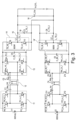
- Fig.3 a detailed structure of the power side of the roller test bench is shown.
- a first bidirectional converter Bi1 and a second bidirectional converter Bi2 are provided in parallel on the feed.
- a step-down converter bridge is arranged downstream of the bidirectional converters Bi1 and Bi2.
- the power unit B which is fed via the common intermediate circuit 4, supplies the desired energy to the terminals C in order to enable charging/discharging of the vehicle battery or the vehicle.
- two input transistor bridges 11, 11' are provided, which are connected to the common intermediate circuit 4 on an input side.
- the transformer 12 is arranged on an output side of the input transistor bridges 11, 11' for galvanic isolation.
- the Fig.3 shown Current sources V1 and V2 are fed from the common intermediate circuit 4.
- the transistor bridge 11 (Z1-Z4) feeds the transformer T1, which is a transformer 12 for galvanic isolation.
- the output transistor bridge 13 is arranged downstream of the transformer 12.
- the output transistor bridge 13 is an active rectifier when energy flows from the intermediate circuit towards the battery or vehicle.
- the output transistor bridge 13 is an inverter and the input transistor bridge 11 is a rectifier.
- the transistor half-bridge Z9, Z10 is, for example, a step-up/step-down converter 14 and supplies the voltage or current for the vehicle battery or the vehicle via a smoothing choke 15 and a filter capacitor 16.
- the circuit structure comprising the input transistor bridge 11, the transformer 12, the output transistor bridge 13, as well as the step-up/step-down converter 14 and the smoothing choke and the filter capacitor can be found in Fig.3 again in the lower part of the circuit at the output transistor bridge 13' and the boost-buck converter 14', which can also be referred to as the second output transistor bridge 13' and the second boost-buck converter 14'.
- This provides two functionally identical circuits (upper coupling element and lower coupling element), with the two boost-buck converters 14 and 14' connected in parallel to achieve higher output currents.
- the maximum output voltage is lower than the output voltage before the galvanic isolation.
- FIG.4 Similar to Fig.3 Two coupling elements are provided, whereby the one in Fig.4
- the circuit structure shown makes it possible to operate the 650 volt intermediate circuit for vehicles or batteries with higher voltages.
- the input transistor bridges 11 and 11' are connected in parallel to the common intermediate circuit 4.
- the two boost/buck converters 14 and 14' are, however, connected in series. This circuit thus results in a three-level buck converter.
- the switching elements therefore only have to switch half the output voltage.
- the maximum output voltage is twice the voltage of the common intermediate circuit 4, but can advantageously be limited to 1,000 volts, for example.
- a current measuring source 17 can be provided at the feed into the common intermediate circuit 4, which can be used, for example, in Fig.2 is shown. Parallel operation of the roller test bench and the battery charging operation can overload the feed-in device such as the Active Front End converter. In such a situation, the current feed-in via the boost/buck converter can be reduced so that the maximum possible current is not exceeded at the current measuring point 17.
- the energy in the test bench can thus be used regeneratively.
- the vehicle's energy can therefore be fed into the intermediate circuit and thus be available for charging the battery and/or feeding back into the grid.
Landscapes
- Engineering & Computer Science (AREA)
- Power Engineering (AREA)
- Physics & Mathematics (AREA)
- General Physics & Mathematics (AREA)
- Electric Propulsion And Braking For Vehicles (AREA)
Claims (13)
- Banc d'essai à rouleaux pour des véhicules (F) au moins partiellement entraînés électriquement, comprenant- une machine électrique (6) pour entraîner ou décélérer au moins un rouleau de roulement (L) du banc d'essai à rouleaux, l'au moins un rouleau de roulement (L) étant prévu pour entrer en contact avec les roues du véhicule (F) à tester ; et- un dispositif de commande qui comprend une unité d'alimentation d'entraînement (A) et une unité de puissance (B) ;dans lequel
l'unité d'alimentation d'entraînement (A) est prévue pour commander la machine électrique (6) et est en liaison avec un réseau d'alimentation, l'unité de puissance (B) pouvant être mise en contact avec au moins une borne (C) pour la liaison électrique avec le véhicule (F) et l'unité de puissance (B) et l'unité d'alimentation d'entraînement (A) étant reliées par l'intermédiaire d'un circuit intermédiaire commun (4), et l'unité de puissance (B) étant alimentée par l'intermédiaire du circuit intermédiaire commun (4), de telle sorte qu'une énergie absorbée par le banc d'essai à rouleaux puisse être acheminée par l'intermédiaire de l'unité de puissance (B) à une batterie de véhicule ou inversement la batterie de véhicule puisse réinjecter de l'énergie par l'intermédiaire de l'unité d'alimentation d'entraînement (A) pour entraîner une machine électrique (6) du banc d'essai à rouleaux, de telle sorte qu'un rendement énergétique optimal puisse être obtenu par un fonctionnement parallèle du banc d'essai à rouleaux et du mode de charge de batterie de véhicule. - Banc d'essai à rouleaux selon la revendication 1, dans lequel l'unité de puissance (B) comprend un organe de couplage (7) pour le découplage galvanique de l'unité de puissance (B) du circuit intermédiaire (4) et/ou du réseau d'alimentation et dans lequel l'organe de couplage (7) comprend de préférence un transformateur (12) pour une séparation galvanique.
- Banc d'essai à rouleaux selon au moins l'une quelconque des revendications précédentes, dans lequel l'unité de puissance (B) est une unité de conditionnement pour conditionner une batterie de véhicule, de telle sorte qu'un état de charge de la batterie de véhicule puisse être réglé.
- Banc d'essai à rouleaux selon au moins l'une quelconque des revendications précédentes, dans lequel l'unité de puissance (B) est réalisée de manière bidirectionnelle, de telle sorte que de l'énergie électrique puisse être acheminée par l'intermédiaire de la borne (C) à un véhicule et évacuée,l'énergie électrique évacuée étant injectée de préférence dans le circuit intermédiaire commun (4) pour alimenter la machine électrique (6) par l'intermédiaire de l'unité d'alimentation d'entraînement (A) ; etl'énergie électrique acheminée étant prélevée de préférence à partir du circuit intermédiaire commun (4).
- Banc d'essai à rouleaux selon au moins l'une quelconque des revendications 2 à 4, dans lequel l'organe de couplage (7) comprend un pont de transistor d'entrée (11, 11') qui est connecté au circuit intermédiaire commun (4) et au transformateur (12), et l'organe de couplage (7) comprend un pont de transistor de sortie (13, 13') qui est connecté au transformateur (12), et dans lequel le pont de transistor d'entrée (11, 11') est connecté à une première bobine du transformateur (12) et le pont de transistor de sortie (13, 13') est connecté à une deuxième bobine du transformateur (12).
- Banc d'essai à rouleaux selon au moins l'une quelconque des revendications 2 à 5, dans lequel l'organe de couplage (7) est connecté au niveau d'un côté d'entrée au circuit intermédiaire commun (4) et est connecté au niveau du côté de sortie à au moins un convertisseur élévateur-abaisseur (14, 14'), le convertisseur élévateur-abaisseur (14, 14') étant en liaison électrique avec la borne (C) de telle sorte qu'une alimentation électrique soit fournie pour l'alimentation d'un véhicule par l'intermédiaire de la borne (C), et une inductance de lissage et un condensateur de filtrage (16) étant prévus entre le convertisseur élévateur-abaisseur (14, 14') et la borne (C).
- Banc d'essai à rouleaux selon au moins l'une quelconque des revendications 2 à 6, dans lequel l'unité de puissance (B) présente un premier organe de couplage (7) avec un premier pont de transistor d'entrée (11) et un deuxième organe de couplage (7') avec un deuxième pont de transistor d'entrée (11') et le premier pont de transistor d'entrée (11) et le deuxième pont de transistor d'entrée (11') sont connectés en parallèle au circuit intermédiaire commun (4).
- Banc d'essai à rouleaux selon au moins l'une quelconque des revendications 5 à 7, dans lequel l'unité de puissance (B) est configurée de telle sorte que lors de la charge du véhicule (F), le pont de transistor d'entrée (11, 11') alimente le transformateur (12) et le pont de transistor de sortie (13, 13') est commuté en tant que redresseur actif et lors de la décharge du véhicule (F), le pont de transistor de sortie (13, 13') est commuté en tant qu'onduleur et le pont de transistor d'entrée (11, 11') est commuté en tant que redresseur.
- Banc d'essai à rouleaux selon au moins l'une quelconque des revendications précédentes, dans lequel l'unité de puissance (B) sert de source de tension dans le fonctionnement motorisé du véhicule (F) à tester et sert de puits de tension dans le fonctionnement générateur du véhicule (F) à tester.
- Banc d'essai à rouleaux selon au moins l'une quelconque des revendications précédentes, dans lequel le circuit intermédiaire commun (4) est un circuit intermédiaire à tension continue qui est alimenté en courant continu, et l'unité de puissance (B) est configurée de telle sorte que le courant au niveau d'un point de mesure (17) au niveau du circuit intermédiaire commun (4) ne dépasse pas une valeur définie.
- Banc d'essai à rouleaux selon au moins l'une quelconque des revendications précédentes, dans lequel les convertisseurs élévateurs-abaisseurs (14, 14') sont commutés en parallèle au circuit intermédiaire commun (4) pour l'augmentation du courant, et/ou les convertisseurs élévateurs-abaisseurs (14, 14') sont commutés en série pour l'augmentation de la tension de sortie supérieure à la tension dans le circuit intermédiaire commun (4).
- Procédé pour faire fonctionner un banc d'essai à rouleaux selon au moins l'une quelconque des revendications 1 à 11 précédentes, dans lequel lors d'une opération de décharge du véhicule, de l'énergie électrique est alimentée par l'intermédiaire de l'unité de puissance (B) dans le circuit intermédiaire commun (4) et lors d'une opération de charge, de l'énergie électrique est alimentée à partir du circuit intermédiaire commun (4) dans le véhicule (F) et l'énergie absorbée par le rouleau de roulement (L) dans un mode de poussée du banc d'essai à rouleaux est réinjectée dans le circuit intermédiaire commun (4) et l'énergie réinjectée peut être acheminée à partir du circuit intermédiaire commun (4) par l'intermédiaire de l'unité de puissance (B) à un véhicule (F), et l'énergie pouvant être acheminée par l'unité de puissance (B) à un véhicule (F), et l'énergie évacuée par l'unité de puissance (B) du véhicule (F) étant réinjectée dans le circuit intermédiaire commun (4) et l'énergie réinjectée pouvant être acheminée à partir du circuit intermédiaire commun (4) par l'intermédiaire de l'unité d'entraînement (A) à la machine électrique (6), de telle sorte qu'un rendement énergétique optimal puisse être obtenu par un fonctionnement parallèle du banc d'essai à rouleaux et du mode de charge de batterie de véhicule,
- Procédé pour faire fonctionner un banc d'essai à rouleaux selon la revendication 12 précédente, dans lequel l'unité de puissance (B) accorde la priorité lors de la charge d'un véhicule (F) au niveau du banc d'essai, de telle sorte qu'un bloc d'alimentation (1) du banc d'essai à rouleaux ne soit pas surchargé, dans lequel, lorsque le véhicule est alimenté par l'unité de puissance (B), le bloc d'alimentation (1) est moins chargé que l'unité d'alimentation d'entraînement (A) et l'unité de puissance (B), de telle sorte que le bloc d'alimentation puisse être dimensionné plus petit, car le bloc d'alimentation (1) ne compense que les pertes, le circuit d'énergie principal étant présent entre l'unité de puissance (B), le moteur de véhicule, le rouleau de roulement (L) avec la machine électrique (6), les convertisseurs de fréquence (5) et le circuit intermédiaire commun (4).
Applications Claiming Priority (2)
| Application Number | Priority Date | Filing Date | Title |
|---|---|---|---|
| DE102018217965.4A DE102018217965A1 (de) | 2018-10-19 | 2018-10-19 | Rollenprüfstand und Verfahren zum Betreiben eines Rollenprüfstands |
| PCT/EP2019/078562 WO2020079275A1 (fr) | 2018-10-19 | 2019-10-21 | Banc d'essai à rouleaux et procédé servant à faire fonctionner un banc d'essai à rouleaux |
Publications (2)
| Publication Number | Publication Date |
|---|---|
| EP3867620A1 EP3867620A1 (fr) | 2021-08-25 |
| EP3867620B1 true EP3867620B1 (fr) | 2024-08-14 |
Family
ID=68342910
Family Applications (1)
| Application Number | Title | Priority Date | Filing Date |
|---|---|---|---|
| EP19794121.4A Active EP3867620B1 (fr) | 2018-10-19 | 2019-10-21 | Banc d'essai à rouleaux et procédé servant à faire fonctionner un banc d'essai à rouleaux |
Country Status (3)
| Country | Link |
|---|---|
| EP (1) | EP3867620B1 (fr) |
| DE (1) | DE102018217965A1 (fr) |
| WO (1) | WO2020079275A1 (fr) |
Families Citing this family (1)
| Publication number | Priority date | Publication date | Assignee | Title |
|---|---|---|---|---|
| AT523185B1 (de) * | 2020-03-05 | 2021-11-15 | Avl List Gmbh | Prüfstand für den Antrieb eines Fahrzeugs |
Family Cites Families (3)
| Publication number | Priority date | Publication date | Assignee | Title |
|---|---|---|---|---|
| DE19900620A1 (de) | 1999-01-11 | 2000-07-13 | Maha Gmbh & Co Kg | Rollenprüfstand für Kraftfahrzeuge |
| US9086333B2 (en) * | 2011-06-16 | 2015-07-21 | Horiba Instruments Incorporated | Examination system for electric vehicle or hybrid electric vehicle |
| KR101334277B1 (ko) * | 2012-04-09 | 2013-11-27 | 한국에너지기술연구원 | 전기 이륜차 시험장치 및 시험제어방법 |
-
2018
- 2018-10-19 DE DE102018217965.4A patent/DE102018217965A1/de active Pending
-
2019
- 2019-10-21 WO PCT/EP2019/078562 patent/WO2020079275A1/fr not_active Ceased
- 2019-10-21 EP EP19794121.4A patent/EP3867620B1/fr active Active
Also Published As
| Publication number | Publication date |
|---|---|
| WO2020079275A1 (fr) | 2020-04-23 |
| EP3867620A1 (fr) | 2021-08-25 |
| DE102018217965A1 (de) | 2020-04-23 |
Similar Documents
| Publication | Publication Date | Title |
|---|---|---|
| EP3521099B1 (fr) | Système de charge doté d'au moins une colonne de charge pour véhicules électriques et procédé de charge d'un ou d'une pluralité de véhicules électriques | |
| DE102011075927B4 (de) | Multifunktionaler stromrichter von gleichspannung zu gleichspannung, von gleichspannung zu wechselspannung und von wechselspannung zu gleichspannung | |
| EP2541755B1 (fr) | Dispositif d'entraînement pour un véhicule | |
| DE102012210448B4 (de) | Elektro- oder Hybridfahrzeug mit einem ein mehrstufiges Stromversorgungssystem umfassenden Fahrzeugbatterieladegerät | |
| DE102015110023A1 (de) | Ladestation und Verfahren zum Laden eines Plug-In-Kraftfahrzeuges an einer Ladesäule | |
| WO2006100264A2 (fr) | Dispositif et procede pour l'equilibrage de charge de cellules individuelles disposees en rangee d'un accumulateur d'energie | |
| DE102009046501A1 (de) | Batteriesystem mit DC/DC-Umsetzern | |
| DE102012004992A1 (de) | Batterieladevorrichtung | |
| DE102009007737A1 (de) | Energiewandlervorrichtung für ein Kraftfahrzeug und entsprechendes Ladegerät | |
| DE102016123923A1 (de) | Ladevorrichtung | |
| WO2014009369A2 (fr) | Structure modulaire de stations de charge rapide en courant continu | |
| DE102012008687A1 (de) | Kraftwagen mit einem Hochvolt-Energieversorgungssystem | |
| DE102016122668A1 (de) | Ladesteuersystem für ein Elektrofahrzeug | |
| DE102017206497A1 (de) | Ladevorrichtung und Verfahren zum Laden eines elektrischen Energiespeichers eines Fahrzeugs, sowie Kraftfahrzeug | |
| EP2844513A2 (fr) | Dispositif et procédé permettant d'alimenter un entraînement électrique en courant électrique | |
| EP3867620B1 (fr) | Banc d'essai à rouleaux et procédé servant à faire fonctionner un banc d'essai à rouleaux | |
| DE102016200769B4 (de) | Verbesserte Stromquellenanordnung mit mehreren Stromquellen | |
| DE102020007869A1 (de) | Elektrisches Bordnetzsystem für ein elektrisch angetriebenes Fahrzeug und dazugehöriges Verfahren | |
| DE102014220434A1 (de) | Effizienter Gleichstrom-Gleichstrom-Wandler mit einem breiten Arbeitsbereich | |
| WO2009121575A2 (fr) | Dispositif de charge pour accumulateurs | |
| EP3994021A1 (fr) | Réseau de bord de véhicule | |
| DE102020132162A1 (de) | Fahrzeug und fahrzeugsteuerverfahren | |
| DE102019124827A1 (de) | Kraftfahrzeug mit einer Elektromaschine als Antriebsmaschine und Verfahren zum Betrieb eines Gleichspannungswandlers in einem Kraftfahrzeug | |
| DE102014212930B3 (de) | Vorrichtung zum Bereitstellen einer elektrischen Spannung sowie Antriebsanordnung und Verfahren | |
| DE102014006806A1 (de) | Ladeausgleichsvorrichtung für ein Batteriesystem |
Legal Events
| Date | Code | Title | Description |
|---|---|---|---|
| STAA | Information on the status of an ep patent application or granted ep patent |
Free format text: STATUS: UNKNOWN |
|
| STAA | Information on the status of an ep patent application or granted ep patent |
Free format text: STATUS: THE INTERNATIONAL PUBLICATION HAS BEEN MADE |
|
| PUAI | Public reference made under article 153(3) epc to a published international application that has entered the european phase |
Free format text: ORIGINAL CODE: 0009012 |
|
| STAA | Information on the status of an ep patent application or granted ep patent |
Free format text: STATUS: REQUEST FOR EXAMINATION WAS MADE |
|
| 17P | Request for examination filed |
Effective date: 20210519 |
|
| AK | Designated contracting states |
Kind code of ref document: A1 Designated state(s): AL AT BE BG CH CY CZ DE DK EE ES FI FR GB GR HR HU IE IS IT LI LT LU LV MC MK MT NL NO PL PT RO RS SE SI SK SM TR |
|
| DAV | Request for validation of the european patent (deleted) | ||
| DAX | Request for extension of the european patent (deleted) | ||
| STAA | Information on the status of an ep patent application or granted ep patent |
Free format text: STATUS: EXAMINATION IS IN PROGRESS |
|
| 17Q | First examination report despatched |
Effective date: 20220912 |
|
| GRAP | Despatch of communication of intention to grant a patent |
Free format text: ORIGINAL CODE: EPIDOSNIGR1 |
|
| STAA | Information on the status of an ep patent application or granted ep patent |
Free format text: STATUS: GRANT OF PATENT IS INTENDED |
|
| INTG | Intention to grant announced |
Effective date: 20240321 |
|
| GRAS | Grant fee paid |
Free format text: ORIGINAL CODE: EPIDOSNIGR3 |
|
| GRAA | (expected) grant |
Free format text: ORIGINAL CODE: 0009210 |
|
| STAA | Information on the status of an ep patent application or granted ep patent |
Free format text: STATUS: THE PATENT HAS BEEN GRANTED |
|
| AK | Designated contracting states |
Kind code of ref document: B1 Designated state(s): AL AT BE BG CH CY CZ DE DK EE ES FI FR GB GR HR HU IE IS IT LI LT LU LV MC MK MT NL NO PL PT RO RS SE SI SK SM TR |
|
| REG | Reference to a national code |
Ref country code: GB Ref legal event code: FG4D Free format text: NOT ENGLISH |
|
| REG | Reference to a national code |
Ref country code: CH Ref legal event code: EP |
|
| REG | Reference to a national code |
Ref country code: DE Ref legal event code: R096 Ref document number: 502019011906 Country of ref document: DE |
|
| REG | Reference to a national code |
Ref country code: IE Ref legal event code: FG4D Free format text: LANGUAGE OF EP DOCUMENT: GERMAN |
|
| REG | Reference to a national code |
Ref country code: LT Ref legal event code: MG9D |
|
| REG | Reference to a national code |
Ref country code: NL Ref legal event code: MP Effective date: 20240814 |
|
| PG25 | Lapsed in a contracting state [announced via postgrant information from national office to epo] |
Ref country code: NO Free format text: LAPSE BECAUSE OF FAILURE TO SUBMIT A TRANSLATION OF THE DESCRIPTION OR TO PAY THE FEE WITHIN THE PRESCRIBED TIME-LIMIT Effective date: 20241114 |
|
| PG25 | Lapsed in a contracting state [announced via postgrant information from national office to epo] |
Ref country code: NL Free format text: LAPSE BECAUSE OF FAILURE TO SUBMIT A TRANSLATION OF THE DESCRIPTION OR TO PAY THE FEE WITHIN THE PRESCRIBED TIME-LIMIT Effective date: 20240814 Ref country code: GR Free format text: LAPSE BECAUSE OF FAILURE TO SUBMIT A TRANSLATION OF THE DESCRIPTION OR TO PAY THE FEE WITHIN THE PRESCRIBED TIME-LIMIT Effective date: 20241115 Ref country code: FI Free format text: LAPSE BECAUSE OF FAILURE TO SUBMIT A TRANSLATION OF THE DESCRIPTION OR TO PAY THE FEE WITHIN THE PRESCRIBED TIME-LIMIT Effective date: 20240814 Ref country code: PL Free format text: LAPSE BECAUSE OF FAILURE TO SUBMIT A TRANSLATION OF THE DESCRIPTION OR TO PAY THE FEE WITHIN THE PRESCRIBED TIME-LIMIT Effective date: 20240814 Ref country code: PT Free format text: LAPSE BECAUSE OF FAILURE TO SUBMIT A TRANSLATION OF THE DESCRIPTION OR TO PAY THE FEE WITHIN THE PRESCRIBED TIME-LIMIT Effective date: 20241216 |
|
| PG25 | Lapsed in a contracting state [announced via postgrant information from national office to epo] |
Ref country code: BG Free format text: LAPSE BECAUSE OF FAILURE TO SUBMIT A TRANSLATION OF THE DESCRIPTION OR TO PAY THE FEE WITHIN THE PRESCRIBED TIME-LIMIT Effective date: 20240814 |
|
| PG25 | Lapsed in a contracting state [announced via postgrant information from national office to epo] |
Ref country code: LV Free format text: LAPSE BECAUSE OF FAILURE TO SUBMIT A TRANSLATION OF THE DESCRIPTION OR TO PAY THE FEE WITHIN THE PRESCRIBED TIME-LIMIT Effective date: 20240814 |
|
| PG25 | Lapsed in a contracting state [announced via postgrant information from national office to epo] |
Ref country code: IS Free format text: LAPSE BECAUSE OF FAILURE TO SUBMIT A TRANSLATION OF THE DESCRIPTION OR TO PAY THE FEE WITHIN THE PRESCRIBED TIME-LIMIT Effective date: 20241214 |
|
| PG25 | Lapsed in a contracting state [announced via postgrant information from national office to epo] |
Ref country code: HR Free format text: LAPSE BECAUSE OF FAILURE TO SUBMIT A TRANSLATION OF THE DESCRIPTION OR TO PAY THE FEE WITHIN THE PRESCRIBED TIME-LIMIT Effective date: 20240814 |
|
| PG25 | Lapsed in a contracting state [announced via postgrant information from national office to epo] |
Ref country code: ES Free format text: LAPSE BECAUSE OF FAILURE TO SUBMIT A TRANSLATION OF THE DESCRIPTION OR TO PAY THE FEE WITHIN THE PRESCRIBED TIME-LIMIT Effective date: 20240814 Ref country code: RS Free format text: LAPSE BECAUSE OF FAILURE TO SUBMIT A TRANSLATION OF THE DESCRIPTION OR TO PAY THE FEE WITHIN THE PRESCRIBED TIME-LIMIT Effective date: 20241114 |
|
| PG25 | Lapsed in a contracting state [announced via postgrant information from national office to epo] |
Ref country code: RS Free format text: LAPSE BECAUSE OF FAILURE TO SUBMIT A TRANSLATION OF THE DESCRIPTION OR TO PAY THE FEE WITHIN THE PRESCRIBED TIME-LIMIT Effective date: 20241114 Ref country code: PT Free format text: LAPSE BECAUSE OF FAILURE TO SUBMIT A TRANSLATION OF THE DESCRIPTION OR TO PAY THE FEE WITHIN THE PRESCRIBED TIME-LIMIT Effective date: 20241216 Ref country code: PL Free format text: LAPSE BECAUSE OF FAILURE TO SUBMIT A TRANSLATION OF THE DESCRIPTION OR TO PAY THE FEE WITHIN THE PRESCRIBED TIME-LIMIT Effective date: 20240814 Ref country code: NO Free format text: LAPSE BECAUSE OF FAILURE TO SUBMIT A TRANSLATION OF THE DESCRIPTION OR TO PAY THE FEE WITHIN THE PRESCRIBED TIME-LIMIT Effective date: 20241114 Ref country code: NL Free format text: LAPSE BECAUSE OF FAILURE TO SUBMIT A TRANSLATION OF THE DESCRIPTION OR TO PAY THE FEE WITHIN THE PRESCRIBED TIME-LIMIT Effective date: 20240814 Ref country code: LV Free format text: LAPSE BECAUSE OF FAILURE TO SUBMIT A TRANSLATION OF THE DESCRIPTION OR TO PAY THE FEE WITHIN THE PRESCRIBED TIME-LIMIT Effective date: 20240814 Ref country code: IS Free format text: LAPSE BECAUSE OF FAILURE TO SUBMIT A TRANSLATION OF THE DESCRIPTION OR TO PAY THE FEE WITHIN THE PRESCRIBED TIME-LIMIT Effective date: 20241214 Ref country code: HR Free format text: LAPSE BECAUSE OF FAILURE TO SUBMIT A TRANSLATION OF THE DESCRIPTION OR TO PAY THE FEE WITHIN THE PRESCRIBED TIME-LIMIT Effective date: 20240814 Ref country code: GR Free format text: LAPSE BECAUSE OF FAILURE TO SUBMIT A TRANSLATION OF THE DESCRIPTION OR TO PAY THE FEE WITHIN THE PRESCRIBED TIME-LIMIT Effective date: 20241115 Ref country code: FI Free format text: LAPSE BECAUSE OF FAILURE TO SUBMIT A TRANSLATION OF THE DESCRIPTION OR TO PAY THE FEE WITHIN THE PRESCRIBED TIME-LIMIT Effective date: 20240814 Ref country code: ES Free format text: LAPSE BECAUSE OF FAILURE TO SUBMIT A TRANSLATION OF THE DESCRIPTION OR TO PAY THE FEE WITHIN THE PRESCRIBED TIME-LIMIT Effective date: 20240814 Ref country code: BG Free format text: LAPSE BECAUSE OF FAILURE TO SUBMIT A TRANSLATION OF THE DESCRIPTION OR TO PAY THE FEE WITHIN THE PRESCRIBED TIME-LIMIT Effective date: 20240814 |
|
| PG25 | Lapsed in a contracting state [announced via postgrant information from national office to epo] |
Ref country code: RO Free format text: LAPSE BECAUSE OF FAILURE TO SUBMIT A TRANSLATION OF THE DESCRIPTION OR TO PAY THE FEE WITHIN THE PRESCRIBED TIME-LIMIT Effective date: 20240814 Ref country code: DK Free format text: LAPSE BECAUSE OF FAILURE TO SUBMIT A TRANSLATION OF THE DESCRIPTION OR TO PAY THE FEE WITHIN THE PRESCRIBED TIME-LIMIT Effective date: 20240814 Ref country code: SM Free format text: LAPSE BECAUSE OF FAILURE TO SUBMIT A TRANSLATION OF THE DESCRIPTION OR TO PAY THE FEE WITHIN THE PRESCRIBED TIME-LIMIT Effective date: 20240814 |
|
| PG25 | Lapsed in a contracting state [announced via postgrant information from national office to epo] |
Ref country code: EE Free format text: LAPSE BECAUSE OF FAILURE TO SUBMIT A TRANSLATION OF THE DESCRIPTION OR TO PAY THE FEE WITHIN THE PRESCRIBED TIME-LIMIT Effective date: 20240814 |
|
| PG25 | Lapsed in a contracting state [announced via postgrant information from national office to epo] |
Ref country code: CZ Free format text: LAPSE BECAUSE OF FAILURE TO SUBMIT A TRANSLATION OF THE DESCRIPTION OR TO PAY THE FEE WITHIN THE PRESCRIBED TIME-LIMIT Effective date: 20240814 |
|
| PG25 | Lapsed in a contracting state [announced via postgrant information from national office to epo] |
Ref country code: SK Free format text: LAPSE BECAUSE OF FAILURE TO SUBMIT A TRANSLATION OF THE DESCRIPTION OR TO PAY THE FEE WITHIN THE PRESCRIBED TIME-LIMIT Effective date: 20240814 Ref country code: IT Free format text: LAPSE BECAUSE OF FAILURE TO SUBMIT A TRANSLATION OF THE DESCRIPTION OR TO PAY THE FEE WITHIN THE PRESCRIBED TIME-LIMIT Effective date: 20240814 |
|
| REG | Reference to a national code |
Ref country code: DE Ref legal event code: R097 Ref document number: 502019011906 Country of ref document: DE |
|
| REG | Reference to a national code |
Ref country code: CH Ref legal event code: PL |
|
| PLBE | No opposition filed within time limit |
Free format text: ORIGINAL CODE: 0009261 |
|
| STAA | Information on the status of an ep patent application or granted ep patent |
Free format text: STATUS: NO OPPOSITION FILED WITHIN TIME LIMIT |
|
| PG25 | Lapsed in a contracting state [announced via postgrant information from national office to epo] |
Ref country code: MC Free format text: LAPSE BECAUSE OF FAILURE TO SUBMIT A TRANSLATION OF THE DESCRIPTION OR TO PAY THE FEE WITHIN THE PRESCRIBED TIME-LIMIT Effective date: 20240814 |
|
| PG25 | Lapsed in a contracting state [announced via postgrant information from national office to epo] |
Ref country code: LU Free format text: LAPSE BECAUSE OF NON-PAYMENT OF DUE FEES Effective date: 20241021 Ref country code: BE Free format text: LAPSE BECAUSE OF NON-PAYMENT OF DUE FEES Effective date: 20241031 |
|
| PG25 | Lapsed in a contracting state [announced via postgrant information from national office to epo] |
Ref country code: FR Free format text: LAPSE BECAUSE OF NON-PAYMENT OF DUE FEES Effective date: 20241031 |
|
| 26N | No opposition filed |
Effective date: 20250515 |
|
| GBPC | Gb: european patent ceased through non-payment of renewal fee |
Effective date: 20241114 |
|
| PG25 | Lapsed in a contracting state [announced via postgrant information from national office to epo] |
Ref country code: CH Free format text: LAPSE BECAUSE OF NON-PAYMENT OF DUE FEES Effective date: 20241031 |
|
| REG | Reference to a national code |
Ref country code: BE Ref legal event code: MM Effective date: 20241031 |
|
| PG25 | Lapsed in a contracting state [announced via postgrant information from national office to epo] |
Ref country code: SE Free format text: LAPSE BECAUSE OF FAILURE TO SUBMIT A TRANSLATION OF THE DESCRIPTION OR TO PAY THE FEE WITHIN THE PRESCRIBED TIME-LIMIT Effective date: 20240814 |
|
| PG25 | Lapsed in a contracting state [announced via postgrant information from national office to epo] |
Ref country code: GB Free format text: LAPSE BECAUSE OF NON-PAYMENT OF DUE FEES Effective date: 20241114 |
|
| PG25 | Lapsed in a contracting state [announced via postgrant information from national office to epo] |
Ref country code: IE Free format text: LAPSE BECAUSE OF NON-PAYMENT OF DUE FEES Effective date: 20241021 |
|
| REG | Reference to a national code |
Ref country code: AT Ref legal event code: MM01 Ref document number: 1713692 Country of ref document: AT Kind code of ref document: T Effective date: 20241021 |
|
| PGFP | Annual fee paid to national office [announced via postgrant information from national office to epo] |
Ref country code: DE Payment date: 20251031 Year of fee payment: 7 |
|
| PG25 | Lapsed in a contracting state [announced via postgrant information from national office to epo] |
Ref country code: AT Free format text: LAPSE BECAUSE OF NON-PAYMENT OF DUE FEES Effective date: 20241021 |
|
| PG25 | Lapsed in a contracting state [announced via postgrant information from national office to epo] |
Ref country code: CY Free format text: LAPSE BECAUSE OF FAILURE TO SUBMIT A TRANSLATION OF THE DESCRIPTION OR TO PAY THE FEE WITHIN THE PRESCRIBED TIME-LIMIT; INVALID AB INITIO Effective date: 20191021 |
|
| PG25 | Lapsed in a contracting state [announced via postgrant information from national office to epo] |
Ref country code: HU Free format text: LAPSE BECAUSE OF FAILURE TO SUBMIT A TRANSLATION OF THE DESCRIPTION OR TO PAY THE FEE WITHIN THE PRESCRIBED TIME-LIMIT; INVALID AB INITIO Effective date: 20191021 |