EP3867732B1 - Dispositif de commande pour un véhicule - Google Patents
Dispositif de commande pour un véhicule Download PDFInfo
- Publication number
- EP3867732B1 EP3867732B1 EP19752443.2A EP19752443A EP3867732B1 EP 3867732 B1 EP3867732 B1 EP 3867732B1 EP 19752443 A EP19752443 A EP 19752443A EP 3867732 B1 EP3867732 B1 EP 3867732B1
- Authority
- EP
- European Patent Office
- Prior art keywords
- operating
- operating element
- sensors
- actuation
- holding element
- Prior art date
- Legal status (The legal status is an assumption and is not a legal conclusion. Google has not performed a legal analysis and makes no representation as to the accuracy of the status listed.)
- Active
Links
Images


Classifications
-
- G—PHYSICS
- G06—COMPUTING OR CALCULATING; COUNTING
- G06F—ELECTRIC DIGITAL DATA PROCESSING
- G06F3/00—Input arrangements for transferring data to be processed into a form capable of being handled by the computer; Output arrangements for transferring data from processing unit to output unit, e.g. interface arrangements
- G06F3/01—Input arrangements or combined input and output arrangements for interaction between user and computer
- G06F3/016—Input arrangements with force or tactile feedback as computer generated output to the user
-
- G—PHYSICS
- G06—COMPUTING OR CALCULATING; COUNTING
- G06F—ELECTRIC DIGITAL DATA PROCESSING
- G06F3/00—Input arrangements for transferring data to be processed into a form capable of being handled by the computer; Output arrangements for transferring data from processing unit to output unit, e.g. interface arrangements
- G06F3/01—Input arrangements or combined input and output arrangements for interaction between user and computer
- G06F3/03—Arrangements for converting the position or the displacement of a member into a coded form
- G06F3/041—Digitisers, e.g. for touch screens or touch pads, characterised by the transducing means
- G06F3/0414—Digitisers, e.g. for touch screens or touch pads, characterised by the transducing means using force sensing means to determine a position
-
- G—PHYSICS
- G06—COMPUTING OR CALCULATING; COUNTING
- G06F—ELECTRIC DIGITAL DATA PROCESSING
- G06F3/00—Input arrangements for transferring data to be processed into a form capable of being handled by the computer; Output arrangements for transferring data from processing unit to output unit, e.g. interface arrangements
- G06F3/01—Input arrangements or combined input and output arrangements for interaction between user and computer
- G06F3/03—Arrangements for converting the position or the displacement of a member into a coded form
- G06F3/041—Digitisers, e.g. for touch screens or touch pads, characterised by the transducing means
- G06F3/0414—Digitisers, e.g. for touch screens or touch pads, characterised by the transducing means using force sensing means to determine a position
- G06F3/04142—Digitisers, e.g. for touch screens or touch pads, characterised by the transducing means using force sensing means to determine a position the force sensing means being located peripherally, e.g. disposed at the corners or at the side of a touch sensing plate
-
- B—PERFORMING OPERATIONS; TRANSPORTING
- B60—VEHICLES IN GENERAL
- B60K—ARRANGEMENT OR MOUNTING OF PROPULSION UNITS OR OF TRANSMISSIONS IN VEHICLES; ARRANGEMENT OR MOUNTING OF PLURAL DIVERSE PRIME-MOVERS IN VEHICLES; AUXILIARY DRIVES FOR VEHICLES; INSTRUMENTATION OR DASHBOARDS FOR VEHICLES; ARRANGEMENTS IN CONNECTION WITH COOLING, AIR INTAKE, GAS EXHAUST OR FUEL SUPPLY OF PROPULSION UNITS IN VEHICLES
- B60K35/00—Instruments specially adapted for vehicles; Arrangement of instruments in or on vehicles
- B60K35/10—Input arrangements, i.e. from user to vehicle, associated with vehicle functions or specially adapted therefor
-
- B—PERFORMING OPERATIONS; TRANSPORTING
- B60—VEHICLES IN GENERAL
- B60K—ARRANGEMENT OR MOUNTING OF PROPULSION UNITS OR OF TRANSMISSIONS IN VEHICLES; ARRANGEMENT OR MOUNTING OF PLURAL DIVERSE PRIME-MOVERS IN VEHICLES; AUXILIARY DRIVES FOR VEHICLES; INSTRUMENTATION OR DASHBOARDS FOR VEHICLES; ARRANGEMENTS IN CONNECTION WITH COOLING, AIR INTAKE, GAS EXHAUST OR FUEL SUPPLY OF PROPULSION UNITS IN VEHICLES
- B60K35/00—Instruments specially adapted for vehicles; Arrangement of instruments in or on vehicles
- B60K35/20—Output arrangements, i.e. from vehicle to user, associated with vehicle functions or specially adapted therefor
- B60K35/21—Output arrangements, i.e. from vehicle to user, associated with vehicle functions or specially adapted therefor using visual output, e.g. blinking lights or matrix displays
- B60K35/22—Display screens
-
- B—PERFORMING OPERATIONS; TRANSPORTING
- B60—VEHICLES IN GENERAL
- B60K—ARRANGEMENT OR MOUNTING OF PROPULSION UNITS OR OF TRANSMISSIONS IN VEHICLES; ARRANGEMENT OR MOUNTING OF PLURAL DIVERSE PRIME-MOVERS IN VEHICLES; AUXILIARY DRIVES FOR VEHICLES; INSTRUMENTATION OR DASHBOARDS FOR VEHICLES; ARRANGEMENTS IN CONNECTION WITH COOLING, AIR INTAKE, GAS EXHAUST OR FUEL SUPPLY OF PROPULSION UNITS IN VEHICLES
- B60K35/00—Instruments specially adapted for vehicles; Arrangement of instruments in or on vehicles
- B60K35/20—Output arrangements, i.e. from vehicle to user, associated with vehicle functions or specially adapted therefor
- B60K35/25—Output arrangements, i.e. from vehicle to user, associated with vehicle functions or specially adapted therefor using haptic output
-
- B—PERFORMING OPERATIONS; TRANSPORTING
- B60—VEHICLES IN GENERAL
- B60K—ARRANGEMENT OR MOUNTING OF PROPULSION UNITS OR OF TRANSMISSIONS IN VEHICLES; ARRANGEMENT OR MOUNTING OF PLURAL DIVERSE PRIME-MOVERS IN VEHICLES; AUXILIARY DRIVES FOR VEHICLES; INSTRUMENTATION OR DASHBOARDS FOR VEHICLES; ARRANGEMENTS IN CONNECTION WITH COOLING, AIR INTAKE, GAS EXHAUST OR FUEL SUPPLY OF PROPULSION UNITS IN VEHICLES
- B60K35/00—Instruments specially adapted for vehicles; Arrangement of instruments in or on vehicles
- B60K35/20—Output arrangements, i.e. from vehicle to user, associated with vehicle functions or specially adapted therefor
- B60K35/29—Instruments characterised by the way in which information is handled, e.g. showing information on plural displays or prioritising information according to driving conditions
-
- G—PHYSICS
- G06—COMPUTING OR CALCULATING; COUNTING
- G06F—ELECTRIC DIGITAL DATA PROCESSING
- G06F3/00—Input arrangements for transferring data to be processed into a form capable of being handled by the computer; Output arrangements for transferring data from processing unit to output unit, e.g. interface arrangements
- G06F3/01—Input arrangements or combined input and output arrangements for interaction between user and computer
- G06F3/03—Arrangements for converting the position or the displacement of a member into a coded form
- G06F3/041—Digitisers, e.g. for touch screens or touch pads, characterised by the transducing means
- G06F3/0412—Digitisers structurally integrated in a display
-
- B—PERFORMING OPERATIONS; TRANSPORTING
- B60—VEHICLES IN GENERAL
- B60K—ARRANGEMENT OR MOUNTING OF PROPULSION UNITS OR OF TRANSMISSIONS IN VEHICLES; ARRANGEMENT OR MOUNTING OF PLURAL DIVERSE PRIME-MOVERS IN VEHICLES; AUXILIARY DRIVES FOR VEHICLES; INSTRUMENTATION OR DASHBOARDS FOR VEHICLES; ARRANGEMENTS IN CONNECTION WITH COOLING, AIR INTAKE, GAS EXHAUST OR FUEL SUPPLY OF PROPULSION UNITS IN VEHICLES
- B60K2360/00—Indexing scheme associated with groups B60K35/00 or B60K37/00 relating to details of instruments or dashboards
- B60K2360/143—Touch sensitive instrument input devices
-
- B—PERFORMING OPERATIONS; TRANSPORTING
- B60—VEHICLES IN GENERAL
- B60K—ARRANGEMENT OR MOUNTING OF PROPULSION UNITS OR OF TRANSMISSIONS IN VEHICLES; ARRANGEMENT OR MOUNTING OF PLURAL DIVERSE PRIME-MOVERS IN VEHICLES; AUXILIARY DRIVES FOR VEHICLES; INSTRUMENTATION OR DASHBOARDS FOR VEHICLES; ARRANGEMENTS IN CONNECTION WITH COOLING, AIR INTAKE, GAS EXHAUST OR FUEL SUPPLY OF PROPULSION UNITS IN VEHICLES
- B60K2360/00—Indexing scheme associated with groups B60K35/00 or B60K37/00 relating to details of instruments or dashboards
- B60K2360/143—Touch sensitive instrument input devices
- B60K2360/1438—Touch screens
-
- B—PERFORMING OPERATIONS; TRANSPORTING
- B60—VEHICLES IN GENERAL
- B60K—ARRANGEMENT OR MOUNTING OF PROPULSION UNITS OR OF TRANSMISSIONS IN VEHICLES; ARRANGEMENT OR MOUNTING OF PLURAL DIVERSE PRIME-MOVERS IN VEHICLES; AUXILIARY DRIVES FOR VEHICLES; INSTRUMENTATION OR DASHBOARDS FOR VEHICLES; ARRANGEMENTS IN CONNECTION WITH COOLING, AIR INTAKE, GAS EXHAUST OR FUEL SUPPLY OF PROPULSION UNITS IN VEHICLES
- B60K2360/00—Indexing scheme associated with groups B60K35/00 or B60K37/00 relating to details of instruments or dashboards
- B60K2360/16—Type of output information
-
- B—PERFORMING OPERATIONS; TRANSPORTING
- B60—VEHICLES IN GENERAL
- B60K—ARRANGEMENT OR MOUNTING OF PROPULSION UNITS OR OF TRANSMISSIONS IN VEHICLES; ARRANGEMENT OR MOUNTING OF PLURAL DIVERSE PRIME-MOVERS IN VEHICLES; AUXILIARY DRIVES FOR VEHICLES; INSTRUMENTATION OR DASHBOARDS FOR VEHICLES; ARRANGEMENTS IN CONNECTION WITH COOLING, AIR INTAKE, GAS EXHAUST OR FUEL SUPPLY OF PROPULSION UNITS IN VEHICLES
- B60K2360/00—Indexing scheme associated with groups B60K35/00 or B60K37/00 relating to details of instruments or dashboards
- B60K2360/18—Information management
- B60K2360/199—Information management for avoiding maloperation
-
- B—PERFORMING OPERATIONS; TRANSPORTING
- B60—VEHICLES IN GENERAL
- B60K—ARRANGEMENT OR MOUNTING OF PROPULSION UNITS OR OF TRANSMISSIONS IN VEHICLES; ARRANGEMENT OR MOUNTING OF PLURAL DIVERSE PRIME-MOVERS IN VEHICLES; AUXILIARY DRIVES FOR VEHICLES; INSTRUMENTATION OR DASHBOARDS FOR VEHICLES; ARRANGEMENTS IN CONNECTION WITH COOLING, AIR INTAKE, GAS EXHAUST OR FUEL SUPPLY OF PROPULSION UNITS IN VEHICLES
- B60K2360/00—Indexing scheme associated with groups B60K35/00 or B60K37/00 relating to details of instruments or dashboards
- B60K2360/20—Optical features of instruments
- B60K2360/33—Illumination features
-
- B—PERFORMING OPERATIONS; TRANSPORTING
- B60—VEHICLES IN GENERAL
- B60K—ARRANGEMENT OR MOUNTING OF PROPULSION UNITS OR OF TRANSMISSIONS IN VEHICLES; ARRANGEMENT OR MOUNTING OF PLURAL DIVERSE PRIME-MOVERS IN VEHICLES; AUXILIARY DRIVES FOR VEHICLES; INSTRUMENTATION OR DASHBOARDS FOR VEHICLES; ARRANGEMENTS IN CONNECTION WITH COOLING, AIR INTAKE, GAS EXHAUST OR FUEL SUPPLY OF PROPULSION UNITS IN VEHICLES
- B60K2360/00—Indexing scheme associated with groups B60K35/00 or B60K37/00 relating to details of instruments or dashboards
- B60K2360/60—Structural details of dashboards or instruments
- B60K2360/68—Features of instruments
- B60K2360/691—Housings
-
- B—PERFORMING OPERATIONS; TRANSPORTING
- B60—VEHICLES IN GENERAL
- B60K—ARRANGEMENT OR MOUNTING OF PROPULSION UNITS OR OF TRANSMISSIONS IN VEHICLES; ARRANGEMENT OR MOUNTING OF PLURAL DIVERSE PRIME-MOVERS IN VEHICLES; AUXILIARY DRIVES FOR VEHICLES; INSTRUMENTATION OR DASHBOARDS FOR VEHICLES; ARRANGEMENTS IN CONNECTION WITH COOLING, AIR INTAKE, GAS EXHAUST OR FUEL SUPPLY OF PROPULSION UNITS IN VEHICLES
- B60K35/00—Instruments specially adapted for vehicles; Arrangement of instruments in or on vehicles
- B60K35/20—Output arrangements, i.e. from vehicle to user, associated with vehicle functions or specially adapted therefor
- B60K35/28—Output arrangements, i.e. from vehicle to user, associated with vehicle functions or specially adapted therefor characterised by the type of the output information, e.g. video entertainment or vehicle dynamics information; characterised by the purpose of the output information, e.g. for attracting the attention of the driver
-
- G—PHYSICS
- G02—OPTICS
- G02B—OPTICAL ELEMENTS, SYSTEMS OR APPARATUS
- G02B6/00—Light guides; Structural details of arrangements comprising light guides and other optical elements, e.g. couplings
- G02B6/0001—Light guides; Structural details of arrangements comprising light guides and other optical elements, e.g. couplings specially adapted for lighting devices or systems
- G02B6/0011—Light guides; Structural details of arrangements comprising light guides and other optical elements, e.g. couplings specially adapted for lighting devices or systems the light guides being planar or of plate-like form
- G02B6/0033—Means for improving the coupling-out of light from the light guide
- G02B6/005—Means for improving the coupling-out of light from the light guide provided by one optical element, or plurality thereof, placed on the light output side of the light guide
- G02B6/0051—Diffusing sheet or layer
-
- G—PHYSICS
- G06—COMPUTING OR CALCULATING; COUNTING
- G06F—ELECTRIC DIGITAL DATA PROCESSING
- G06F2203/00—Indexing scheme relating to G06F3/00 - G06F3/048
- G06F2203/041—Indexing scheme relating to G06F3/041 - G06F3/045
- G06F2203/04105—Pressure sensors for measuring the pressure or force exerted on the touch surface without providing the touch position
-
- H—ELECTRICITY
- H01—ELECTRIC ELEMENTS
- H01H—ELECTRIC SWITCHES; RELAYS; SELECTORS; EMERGENCY PROTECTIVE DEVICES
- H01H3/00—Mechanisms for operating contacts
- H01H2003/008—Mechanisms for operating contacts with a haptic or a tactile feedback controlled by electrical means, e.g. a motor or magnetofriction
Definitions
- the invention relates to an operating device for a vehicle, for example for a vehicle component such as an air conditioning system, an infotainment system or a navigation system, and very generally a man-machine interface (human-machine interface).
- a vehicle component such as an air conditioning system, an infotainment system or a navigation system
- a man-machine interface human-machine interface
- the object of the invention is to specify an operating device for a vehicle whose design for measuring the triggering force when the display is operated manually is simplified.
- control element has a display with an information displaying front, the User interface of the control forms.
- the display can have a cover panel that defines the user interface, with a display unit arranged behind it for the visual display of information.
- the cover pane expediently protrudes beyond the display unit on all sides, with this protruding area forming the boundary edge area of the control element.
- the displays that are predominantly used in operating devices today work with LCD technology.
- Such displays are equipped with backlighting units.
- the holding element which supports the operating element in the operating device according to the invention, is used to hold such a backlighting unit.
- displays are also used in which the individual pixels light up automatically, so to speak, when they are required to display information.
- the display is not designed as a kind of shutter, but is provided with individual pixels that can be actively controlled for lighting.
- An example of such a display is, for example, an OLED display.
- a backlighting unit is no longer required.
- the holding element fulfills the function of mechanical protection for the back of the display, which the holding element also performs when the display has a backlighting unit accommodated by the holding element. In both cases, the holding element more or less covers the back of the display.
- the holding element is essentially designed as a trough-shaped or trough-shaped element which has a bottom wall from which supporting parts preferably protrude on all edge sections.
- the bottom wall has a peripheral, projecting peripheral wall, which expediently merges into a likewise peripheral flange.
- the support parts are then designed as those side wall sections which protrude from the bottom wall along each edge section thereof.
- individual, separate and thus spaced support parts protrude from the bottom wall, preferably on all edge sections.
- the support parts are coupled to the operating element in a boundary edge area of the latter.
- the operating element itself has a front side forming the operating surface, a rear side and the previously mentioned surrounding boundary edge area.
- the holding element itself is located in the housing of the operating device, which has a front side which has a receiving opening delimited by an opening edge, within which the operating element is arranged.
- the housing also has a back wall. Finally, the housing also has side walls.
- a special feature of the operating device according to the invention can be seen in the fact that the holding element is rigidly connected to the rear wall of the housing in a central area of its bottom wall.
- the rear wall therefore supports the retaining element in this middle area of the bottom wall. Outside the central area, i.e. in the vicinity of the central area of the bottom wall, the holding element is spaced from the rear wall of the housing; An annular gap forms between the retaining element and the rear wall.
- the holding element and in particular its bottom wall are subjected to a bending moment. Because the force with which you manually oppose the user interface of the control element is pressed is transmitted to the bottom wall via the boundary edge area of the operating element and the support parts mechanically coupled to this boundary edge area. Since the bottom wall is mounted centrally and otherwise has a gap to the rear wall of the housing, the bottom wall can now deform like a bending beam clamped on one side or absorb corresponding bending moments. These are transmitted to actuation sensors located between the area surrounding the center area of the bottom wall and the rear wall of the housing. The actuation sensors can be designed as displacement and/or as force and/or as pressure sensors.
- MEMS components microelectronic mechanical sensors
- the measurement signals from the actuation sensors are transmitted to an evaluation unit which, among other things, has a microprocessor with a corresponding hardware environment.
- the measurement signals of the actuation sensors are evaluated in the evaluation unit, specifically for the purpose of recognizing a valid manual actuation, ie an actuation of the operating element with a definable minimum pressing force. Incorrect operation of the control element can thus be ruled out.
- the operating device is characterized by a compact design.
- the shear-resistant connection of the holding element to the rear wall of the housing allows an actuator to be provided between the holding element and the operating element for any desired haptic feedback from the operating device.
- the actuator would be supported on the one hand on the holding element in order to mechanically stimulate the control element in a pulsed manner, for example for the purpose of lateral pulsed movement of the control element, which can be manually detected tactilely and thus provides tactile feedback on a valid actuation of the control element.
- the evaluation unit also evaluates the signals of the actuation sensors for the purpose of recognizing that position on the user interface of the control element at which the manual actuation of the control element takes place.
- control element can be provided with a touch sensor system for detecting that position on the user interface of the control element at which the manual actuation of the control element takes place.
- the touch sensors can work capacitively, resistively or optically. If MEMS are used, the bending moment to which the bottom wall of the holding element is exposed when the user interface of the operating element is actuated manually can be attributed to bending beams, bending membranes or the like. are transmitted, the mechanical bending of these micromechanical elements of the MEMS being detected by transistor or resistance measurement pressures or other micromechanical, microelectrical components.
- the support parts and the boundary edge area of the operating element can be rigidly connected to one another.
- the operating device can also be equipped with a haptic feedback functionality.
- the procedure is such that the user interface is mechanically stimulated when a valid actuation has been detected.
- the operating element together with the holding element would have to be connected elastically.
- the control element then remains for mechanical stimulation for the haptic feedback functionality, which for this purpose is connected elastically and thus resiliently to the supporting parts of the holding element have to be.
- a variant of the invention proposes that the support parts and the boundary edge area of the operating element are mechanically coupled to one another by means of a resilient connecting element arranged between them.
- the connecting element can be sheared resiliently after compression occurring perpendicularly to the operating surface of the operating element and can be sheared resiliently when the operating element is displaced orthogonally thereto.
- material for that Connecting element is suitable elastomeric material such as rubber or silicone.
- the connecting element is expediently designed as a strip of material which preferably runs along the entire boundary edge area and mechanically couples it to the supporting parts of the holding element. Due to the geometric shape of the strip material, its elasticity can be influenced within certain limits perpendicularly to the user interface and transversely to it. It is also possible to use composite material, ie elastomeric material and rigid bodies embedded in it, which greatly reduce or completely prevent the compressibility perpendicular to the operating surface, but nonetheless continue to ensure the shearability of the connecting element directed transversely thereto.
- the control element has a display with a front side showing information, which forms the user interface of the control element.
- the display can have a cover panel that defines the user interface, with a display unit arranged behind it for the visual display of information.
- the cover pane expediently protrudes beyond the display unit on all sides, with this protruding area forming the boundary edge area of the control element.
- the displays that are predominantly used in operating devices today work with LCD technology.
- Such displays are equipped with backlighting units.
- the holding element which supports the operating element in the operating device according to the invention, can now expediently be used to hold such a backlighting unit.
- displays are also used in which the individual pixels light up automatically, so to speak, when they are required to display information.
- the display is not designed as a kind of shutter, but is provided with individual pixels that can be actively controlled for lighting.
- An example of such a display is, for example, an OLED display.
- a backlighting unit is no longer required.
- the retaining element fulfills the function of mechanically protecting the back of the display also exercises the holding element when the display has a backlighting unit held by the holding element. In both cases, the holding element more or less covers the back of the display.
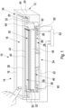
- the operating device 10 has a housing 12 which has a receiving opening 16 on its front side 14, within which an operating element 18 with an operating surface 20 is arranged.
- the housing also has a rear wall 22 which is connected to the front side 14 of the housing 12 via side walls 24 .
- a trough-shaped holding element 26 Inside the housing 12 there is a trough-shaped holding element 26 in this exemplary embodiment, which has a bottom wall 28 from which support parts 30 protrude on all sides of the bottom wall 28 and merge into an outwardly pointing mounting flange 32 .
- the mounting flange 32 is mechanically coupled to the peripheral boundary edge area 34 of the operating element 18 .
- the operating element 18 is in the form of a display 36 .
- the display 36 has a cover plate 38 whose front forms the user interface 20 of the control element 18 .
- the display unit 40 (implemented for example using LCD technology) is located behind the cover plate 38 .
- the display 36 can also have a touch sensor system in the form of a touch panel 42 .
- Such displays are fundamentally known in the prior art and will not be described further here.
- this is resiliently connected to the mounting flange 32.
- This is done by a connecting element 44, which in this embodiment is positioned along the mounting flange 32 running elastomeric band is performed.
- the connecting element is bonded, for example, to the mounting flange 32 and to the cover plate 38 in a shear-resistant manner.
- a backlighting unit 46 for backlighting the display 36, which has a light guide element 48 and a diffuser 50 for homogenizing the light emitted by the light guide element 48 in the direction of the display 36 light.
- light is fed into the light guide element 48 via LEDs arranged on the inside of the support elements as light sources 52 .
- This technology is also known in principle and will not be explained further here.
- a special feature of the operating device 10 according to 1 can be seen in the rigid connection of the holding element 26 to the rear wall 22 of the housing 12 . This is in 1 shown.
- a middle area 54 of the bottom wall 28 is connected to the rear wall 22 of the housing 12 .
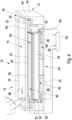
- the surrounding area 56 of the bottom wall 28, which extends around the central area 54 on all sides, is arranged at a distance from the rear wall 22 of the housing 12 (see the gap space 58). In this space, preferably in the corner areas of the bottom wall 28, actuation sensors 60 are located, as shown in 2 is indicated.
- the actuation sensors 60 supply their measurement signals to an evaluation unit 62, which also receives information from the touch sensors (touch panel 42) of the display 36.
- the analysis unit 62 now analyzes the signals from the actuation sensors 60 in order to decide whether manual actuation of the user interface 20 pressed against it with a minimum pressing force, which is decisive for a valid actuation of the user interface 20 .
- the operating device 10 is also equipped with a haptic feedback functionality.
- the operating device 10 has a Actuator 64, which is designed for example as an electromagnetic actuator or as a piezoelectric actuator.
- the task of this actuator 64 is to mechanically stimulate the operating element 18 laterally in a pulse-like manner when a valid actuation of the operating element 18 is detected.
- the elastic connecting element 44 is used for this purpose, among other things, which on the one hand allows the force or moment to be transmitted from the operating element 18 via the holding element 26 to the actuating sensors 60 and on the other hand also enables a laterally acting shear.
- FIG. 3 shows the situation at the moment when the user interface 20 is touched manually with a minimum pressing force required for valid actuation.
- the actuation sensors 60 sense a pressing force. If this is greater than the minimum pressing force, evaluation unit 62 emits a control signal to actuator 64, which laterally excites operating element 18 mechanically in the form of pulses, which is shown in 4 with the arrow 66 is indicated.
- the actuating sensors 60 which are opposite the point of contact of the user interface 20 (i.e. the or the two in 3 touch sensors 60 shown on the right) still have contact with the holding element 26. In the case of pressure or force sensors as actuation sensors 60, this may make sense.
- displacement sensors are used as actuation sensors 60, a distance between these sensors and the holding element 26 (if the sensors are arranged on the rear wall 22 of the housing 12) or between these sensors and the rear wall 22 (if these sensors are arranged on the underside of the holding element 26) arise or be present when the operating element 18 is in the idle state.
- the actuation sensors 60 can also be used to determine the location at which the operating element 18 was acted on manually.
- the force with which against If the user interface 20 is pressed manually, depending on the location at which the user interface 20 is acted upon, the effect is as measurement signals of different magnitudes from the plurality of actuation sensors 60 .
- the location of the manual actuation of the user interface 20 can then be deduced by previous corresponding calibration.
Landscapes
- Engineering & Computer Science (AREA)
- General Engineering & Computer Science (AREA)
- Theoretical Computer Science (AREA)
- Mechanical Engineering (AREA)
- Chemical & Material Sciences (AREA)
- Combustion & Propulsion (AREA)
- Transportation (AREA)
- General Physics & Mathematics (AREA)
- Physics & Mathematics (AREA)
- Human Computer Interaction (AREA)
- Mechanical Control Devices (AREA)
- Fittings On The Vehicle Exterior For Carrying Loads, And Devices For Holding Or Mounting Articles (AREA)
- Position Input By Displaying (AREA)
- User Interface Of Digital Computer (AREA)
- Push-Button Switches (AREA)
Claims (9)
- Dispositif de commande pour un véhicule, doté- d'un boîtier (12) doté d'une face avant (14), laquelle comporte une ouverture d'accueil (16) délimitée par un bord d'ouverture, et doté d'une paroi arrière (22),- d'un élément de commande (18) comportant une surface de commande (20) et disposé dans l'ouverture d'accueil (16) à distance du bord d'ouverture de celle-ci, lequel comporte une face avant (20) pourvue de la surface de commande (20) et une face arrière,- d'un élément de fixation (26), lequel comporte une paroi de fond (28) et des pièces d'appui (30) en saillie par rapport à celle-ci, lesquelles se terminent en dessous d'une zone périphérique de délimitation (34) de l'élément de commande (18) et sont mécaniquement couplées à ce dernier dans sa zone périphérique de délimitation (34),- dans lequel la paroi de fond (28) de l'élément de fixation (26) comporte une zone médiane (54) à distance des pièces d'appui (30) et une zone périphérique entourant celle-ci, dans lequel la paroi de fond (28) de l'élément de fixation (26) s'appuie sur la paroi arrière du boîtier (12) dans la zone médiane (54) et dans lequel la zone périphérique de la paroi de fond (28) comporte un écart par rapport à la paroi arrière du boîtier (12),- de plusieurs capteurs d'actionnement (60) détectant un actionnement manuel de l'élément de commande (18), lesquels sont disposés entre la zone périphérique de la paroi de fond (28) de l'élément de fixation (26) et la paroi arrière du boîtier (12), dans lequel les capteurs d'actionnement (60) détectent les couples de flexion s'exerçant sur l'élément de fixation (26) à l'intérieur de sa zone périphérique entourant la zone médiane (54) lors d'un actionnement manuel de l'élément de commande (18), et- d'une unité d'analyse (62), laquelle reçoit des signaux des capteurs d'actionnement (60) et analyse ceux-ci afin de reconnaître un actionnement manuel de l'élément de commande (18) avec une force de pression minimale prédéfinissable,- dans lequel l'élément de commande (18) comporte un écran (36) doté d'une face avant affichant des informations,caractérisé- en ce que l'écran (36) comporte une plaque de protection (38) définissant la surface de commande (20) avec une unité d'affichage (40) disposée derrière cette plaque de protection (38) et destinée à l'affichage optique d'informations,- en ce que la plaque de protection (38) déborde de tous les côtés au-dessus de l'unité d'affichage (40) et cette zone de débordement forme la zone périphérique de délimitation (34) de l'élément de commande (18) et ainsi cette zone de débordement de la plaque de protection (38) est mécaniquement couplée aux pièces d'appui (30) de l'élément de fixation (26) et- en ce que l'élément de fixation (26) accueille une unité de rétroéclairage (46) destinée à rétroéclairer l'unité d'affichage (40).
- Dispositif de commande selon la revendication 1, dans lequel l'unité d'analyse (62) analyse en outre les signaux des capteurs d'actionnement (60) afin de reconnaître sur quelle position de la surface de commande (20) de l'élément de commande (18) s'effectue l'actionnement manuel de l'élément de commande (18).
- Dispositif de commande selon la revendication 1, dans lequel l'élément de commande (18) est pourvu d'un système de capteurs tactiles afin de reconnaître sur quelle position de la surface de commande (20) de l'élément de commande (18) s'effectue l'actionnement manuel de l'élément de commande (18).
- Dispositif de commande selon la revendication 3, dans lequel le système de capteurs tactiles fonctionne de manière capacitive, résistive ou optique.
- Dispositif de commande selon l'une des revendications 1 à 4, dans lequel les pièces d'appui (30) et la zone périphérique de délimitation (34) de l'élément de commande (18) sont liées entre elles de manière rigide.
- Dispositif de commande selon l'une des revendications 1 à 4, dans lequel les pièces d'appui (30) et la zone périphérique de délimitation (34) de l'élément de commande (18) sont couplées mécaniquement entre elles au moyen d'un élément de liaison élastique (44) disposé entre celles-ci.
- Dispositif de commande selon la revendication 6, dans lequel l'élément de liaison (44) peut cisailler de manière élastique après une compression s'effectuant perpendiculairement à la surface de commande (20) de l'élément de commande (18) et lors d'un déplacement s'effectuant de manière orthogonale à une telle compression perpendiculaire à la surface de commande (20).
- Dispositif de commande selon la revendication 6 ou selon la revendication 7, doté en outre d'un actionneur commandable par l'unité d'analyse (62) afin de générer un retour tactile par action mécanique sur l'élément de commande (18) lors d'un actionnement de l'élément de commande (18) s'effectuant avec la force de pression minimale prédéfinie.
- Dispositif de commande selon l'une des revendications 1 à 8, dans lequel les capteurs d'actionnement (60) comportent des capteurs de mouvement et/ou de force et/ou de pression.
Applications Claiming Priority (2)
| Application Number | Priority Date | Filing Date | Title |
|---|---|---|---|
| DE102018125769 | 2018-10-17 | ||
| PCT/EP2019/070595 WO2020078600A1 (fr) | 2018-10-17 | 2019-07-31 | Dispositif de commande pour un véhicule |
Publications (2)
| Publication Number | Publication Date |
|---|---|
| EP3867732A1 EP3867732A1 (fr) | 2021-08-25 |
| EP3867732B1 true EP3867732B1 (fr) | 2023-08-23 |
Family
ID=67587735
Family Applications (1)
| Application Number | Title | Priority Date | Filing Date |
|---|---|---|---|
| EP19752443.2A Active EP3867732B1 (fr) | 2018-10-17 | 2019-07-31 | Dispositif de commande pour un véhicule |
Country Status (7)
| Country | Link |
|---|---|
| US (1) | US11669188B2 (fr) |
| EP (1) | EP3867732B1 (fr) |
| JP (1) | JP7397864B2 (fr) |
| KR (1) | KR102815246B1 (fr) |
| CN (1) | CN112840296B (fr) |
| ES (1) | ES2957708T3 (fr) |
| WO (1) | WO2020078600A1 (fr) |
Families Citing this family (5)
| Publication number | Priority date | Publication date | Assignee | Title |
|---|---|---|---|---|
| KR20230003007A (ko) * | 2020-04-30 | 2023-01-05 | 베르-헬라 테르모콘트롤 게엠베하 | 차량에 설치되는 조작장치 |
| DE102020117200A1 (de) | 2020-06-30 | 2021-12-30 | Marquardt Gmbh | Bedienelement mit einer Bedienoberfläche und einem Vibrationsaktuator zur Erzeugung einer lokal festgelegten Vibration auf der Bedienoberfläche |
| CN115812191A (zh) * | 2021-05-31 | 2023-03-17 | 京东方科技集团股份有限公司 | 触控装置及其工作方法 |
| DE102023113246B3 (de) * | 2023-05-22 | 2024-10-10 | BHTC GmbH | Bedieneinheit für ein Fahrzeug, insbesondere für die Bedienung einer oder mehrerer Komponenten des Fahrzeugs |
| DE102023206185A1 (de) | 2023-06-30 | 2025-01-02 | Robert Bosch Gesellschaft mit beschränkter Haftung | Displayvorrichtung mit Einrichtung zur Kontaktgeräuschminderung |
Family Cites Families (11)
| Publication number | Priority date | Publication date | Assignee | Title |
|---|---|---|---|---|
| JP2010533336A (ja) * | 2007-07-11 | 2010-10-21 | ユイ・ジン・オ | 指の動作感知を利用したデータ入力装置およびこれを利用した入力変換方法 |
| US8169332B2 (en) | 2008-03-30 | 2012-05-01 | Pressure Profile Systems Corporation | Tactile device with force sensitive touch input surface |
| EP2224313B1 (fr) | 2009-02-27 | 2012-12-05 | Research In Motion Limited | Dispositif d'affichage tactile sensible au toucher incluant un capteur de force et dispositif électronique portable l'incluant |
| CN103947113B (zh) * | 2011-09-22 | 2016-12-21 | 贝洱海拉温控系统有限公司 | 操作装置 |
| JP6200361B2 (ja) * | 2014-03-25 | 2017-09-20 | 株式会社フジクラ | 感圧センサ及び入力装置 |
| DE102015200037A1 (de) * | 2015-01-05 | 2016-07-07 | Volkswagen Aktiengesellschaft | Bedienvorrichtung mit verbesserter haptischer Rückmeldung |
| DE102015100630B4 (de) * | 2015-01-16 | 2016-10-20 | Preh Gmbh | Bedienelement mit Kraftsensoren zur berührbereichsauflösender Berührdetektion bei Krafteinwirkung auf eine Betätigungsfläche |
| DE102016002021B3 (de) | 2016-02-20 | 2017-07-20 | Audi Ag | Kraftfahrzeug-Bedienvorrichtung mit federnd gelagertem Betätigungselement und Bedienhaptik |
| DE102016108899A1 (de) | 2016-05-13 | 2017-11-16 | Visteon Global Technologies, Inc. | Kombiniertes Ein- und Ausgabegerät und Verfahren zur Bedienung eines Ein- und Ausgabegerätes |
| EP3309966A1 (fr) * | 2016-10-17 | 2018-04-18 | RAFI GmbH & Co. KG | Dispositif de commutation capacitif |
| US10678364B2 (en) * | 2017-03-23 | 2020-06-09 | Immersion Corporation | System for providing sensor and actuation functionality for touch input device |
-
2019
- 2019-07-31 WO PCT/EP2019/070595 patent/WO2020078600A1/fr not_active Ceased
- 2019-07-31 JP JP2021521109A patent/JP7397864B2/ja active Active
- 2019-07-31 CN CN201980067859.5A patent/CN112840296B/zh active Active
- 2019-07-31 US US17/284,575 patent/US11669188B2/en active Active
- 2019-07-31 EP EP19752443.2A patent/EP3867732B1/fr active Active
- 2019-07-31 ES ES19752443T patent/ES2957708T3/es active Active
- 2019-07-31 KR KR1020217012448A patent/KR102815246B1/ko active Active
Also Published As
| Publication number | Publication date |
|---|---|
| JP7397864B2 (ja) | 2023-12-13 |
| ES2957708T3 (es) | 2024-01-24 |
| US20220197462A1 (en) | 2022-06-23 |
| CN112840296B (zh) | 2024-12-31 |
| KR102815246B1 (ko) | 2025-06-02 |
| US11669188B2 (en) | 2023-06-06 |
| WO2020078600A1 (fr) | 2020-04-23 |
| KR20210061428A (ko) | 2021-05-27 |
| CN112840296A (zh) | 2021-05-25 |
| JP2022507010A (ja) | 2022-01-18 |
| EP3867732A1 (fr) | 2021-08-25 |
Similar Documents
| Publication | Publication Date | Title |
|---|---|---|
| EP3867732B1 (fr) | Dispositif de commande pour un véhicule | |
| EP2972698B1 (fr) | Procédé permettant de faire fonctionner un système de commande tactile et dispositif pourvu d'un tel système de commande | |
| DE102015016499B3 (de) | Bedienvorrichtung für ein Kraftfahrzeug mit einfahrbarem Berührungsbildschirm sowie Kraftfahrzeug und Verfahren hierzu | |
| EP3791246B1 (fr) | Dispositif de commande d'un véhicule | |
| DE102013225463A1 (de) | Bedienvorrichtung für ein elektrisches Gerät oder eine Anlage, insbesondere für eine Fahrzeugkomponente | |
| EP3652615A1 (fr) | Unité de commande pour un appareil | |
| DE102006029506A1 (de) | Eingabevorrichtung | |
| WO2013153048A1 (fr) | Unité de commande pour un appareil de véhicule | |
| DE102010010575A1 (de) | Anzeigevorrichtung für ein Fahrzeug | |
| EP3917796B1 (fr) | Dispositif de commande d'un véhicule | |
| DE102015012178A1 (de) | Berührungsempfindliche Vorrichtung mit haptischer Rückmeldung | |
| EP3080554B1 (fr) | Dispositif de commande pour un appareil électrique, en particulier pour un composant de véhicule à moteur | |
| DE102015100630B4 (de) | Bedienelement mit Kraftsensoren zur berührbereichsauflösender Berührdetektion bei Krafteinwirkung auf eine Betätigungsfläche | |
| DE102018115220A1 (de) | Betätigungsmodul für ein Kraftfahrzeug | |
| EP3172841B1 (fr) | Unité de commande pour un appareil électrique, en particulier pour un composant de véhicule | |
| DE102017212447B4 (de) | Bedienvorrichtung für ein Kraftfahrzeug und Kraftfahrzeug | |
| DE102015015073B4 (de) | Bedienvorrichtung für ein Kraftfahrzeug | |
| DE102015120799A1 (de) | Kraftfahrzeug | |
| DE102018129049A1 (de) | Eingabevorrichtung für ein Kraftfahrzeug mit einem beweglichen Eingabebereich zur Erkennung einer Eingabe sowie ein Armaturenbrett mit solch einer Eingabevorrichtung | |
| DE102014019128A1 (de) | Bedieneinrichtung für ein Kraftfahrzeug, Kraftfahrzeug und Verfahren zum Betreiben einer Bedieneinrichtung | |
| DE102006038293A1 (de) | Eingabevorrichtung | |
| DE202024100451U1 (de) | Bedieneinheit für ein Fahrzeug | |
| DE102016014774A1 (de) | Berührungsempfindliche Anzeigeeinrichtung mit haptischer Rückmeldung | |
| DE102017205494B4 (de) | Berührungssensitive Bedienvorrichtung für ein Kraftfahrzeug und Verfahren zum Betreiben einer berührungssensitiven Bedienvorrichtung | |
| WO2019023725A1 (fr) | Panneau de commande industriel |
Legal Events
| Date | Code | Title | Description |
|---|---|---|---|
| STAA | Information on the status of an ep patent application or granted ep patent |
Free format text: STATUS: UNKNOWN |
|
| STAA | Information on the status of an ep patent application or granted ep patent |
Free format text: STATUS: THE INTERNATIONAL PUBLICATION HAS BEEN MADE |
|
| PUAI | Public reference made under article 153(3) epc to a published international application that has entered the european phase |
Free format text: ORIGINAL CODE: 0009012 |
|
| STAA | Information on the status of an ep patent application or granted ep patent |
Free format text: STATUS: REQUEST FOR EXAMINATION WAS MADE |
|
| 17P | Request for examination filed |
Effective date: 20210517 |
|
| AK | Designated contracting states |
Kind code of ref document: A1 Designated state(s): AL AT BE BG CH CY CZ DE DK EE ES FI FR GB GR HR HU IE IS IT LI LT LU LV MC MK MT NL NO PL PT RO RS SE SI SK SM TR |
|
| DAV | Request for validation of the european patent (deleted) | ||
| DAX | Request for extension of the european patent (deleted) | ||
| REG | Reference to a national code |
Ref country code: DE Ref legal event code: R079 Ref country code: DE Ref legal event code: R079 Ref document number: 502019009070 Country of ref document: DE Free format text: PREVIOUS MAIN CLASS: G06F0003010000 Ipc: B60K0035000000 |
|
| GRAP | Despatch of communication of intention to grant a patent |
Free format text: ORIGINAL CODE: EPIDOSNIGR1 |
|
| STAA | Information on the status of an ep patent application or granted ep patent |
Free format text: STATUS: GRANT OF PATENT IS INTENDED |
|
| RIC1 | Information provided on ipc code assigned before grant |
Ipc: H01H 3/00 20060101ALI20230119BHEP Ipc: G06F 3/01 20060101ALI20230119BHEP Ipc: G06F 3/041 20060101ALI20230119BHEP Ipc: B60K 37/06 20060101ALI20230119BHEP Ipc: B60K 35/00 20060101AFI20230119BHEP |
|
| INTG | Intention to grant announced |
Effective date: 20230210 |
|
| GRAS | Grant fee paid |
Free format text: ORIGINAL CODE: EPIDOSNIGR3 |
|
| GRAA | (expected) grant |
Free format text: ORIGINAL CODE: 0009210 |
|
| STAA | Information on the status of an ep patent application or granted ep patent |
Free format text: STATUS: THE PATENT HAS BEEN GRANTED |
|
| AK | Designated contracting states |
Kind code of ref document: B1 Designated state(s): AL AT BE BG CH CY CZ DE DK EE ES FI FR GB GR HR HU IE IS IT LI LT LU LV MC MK MT NL NO PL PT RO RS SE SI SK SM TR |
|
| REG | Reference to a national code |
Ref country code: GB Ref legal event code: FG4D Free format text: NOT ENGLISH |
|
| REG | Reference to a national code |
Ref country code: CH Ref legal event code: EP |
|
| REG | Reference to a national code |
Ref country code: IE Ref legal event code: FG4D Free format text: LANGUAGE OF EP DOCUMENT: GERMAN |
|
| REG | Reference to a national code |
Ref country code: DE Ref legal event code: R096 Ref document number: 502019009070 Country of ref document: DE |
|
| P01 | Opt-out of the competence of the unified patent court (upc) registered |
Effective date: 20230810 |
|
| REG | Reference to a national code |
Ref country code: SE Ref legal event code: TRGR |
|
| REG | Reference to a national code |
Ref country code: LT Ref legal event code: MG9D |
|
| REG | Reference to a national code |
Ref country code: NL Ref legal event code: MP Effective date: 20230823 |
|
| PG25 | Lapsed in a contracting state [announced via postgrant information from national office to epo] |
Ref country code: GR Free format text: LAPSE BECAUSE OF FAILURE TO SUBMIT A TRANSLATION OF THE DESCRIPTION OR TO PAY THE FEE WITHIN THE PRESCRIBED TIME-LIMIT Effective date: 20231124 |
|
| PG25 | Lapsed in a contracting state [announced via postgrant information from national office to epo] |
Ref country code: IS Free format text: LAPSE BECAUSE OF FAILURE TO SUBMIT A TRANSLATION OF THE DESCRIPTION OR TO PAY THE FEE WITHIN THE PRESCRIBED TIME-LIMIT Effective date: 20231223 |
|
| REG | Reference to a national code |
Ref country code: ES Ref legal event code: FG2A Ref document number: 2957708 Country of ref document: ES Kind code of ref document: T3 Effective date: 20240124 |
|
| PG25 | Lapsed in a contracting state [announced via postgrant information from national office to epo] |
Ref country code: RS Free format text: LAPSE BECAUSE OF FAILURE TO SUBMIT A TRANSLATION OF THE DESCRIPTION OR TO PAY THE FEE WITHIN THE PRESCRIBED TIME-LIMIT Effective date: 20230823 Ref country code: PT Free format text: LAPSE BECAUSE OF FAILURE TO SUBMIT A TRANSLATION OF THE DESCRIPTION OR TO PAY THE FEE WITHIN THE PRESCRIBED TIME-LIMIT Effective date: 20231226 Ref country code: NO Free format text: LAPSE BECAUSE OF FAILURE TO SUBMIT A TRANSLATION OF THE DESCRIPTION OR TO PAY THE FEE WITHIN THE PRESCRIBED TIME-LIMIT Effective date: 20231123 Ref country code: NL Free format text: LAPSE BECAUSE OF FAILURE TO SUBMIT A TRANSLATION OF THE DESCRIPTION OR TO PAY THE FEE WITHIN THE PRESCRIBED TIME-LIMIT Effective date: 20230823 Ref country code: LV Free format text: LAPSE BECAUSE OF FAILURE TO SUBMIT A TRANSLATION OF THE DESCRIPTION OR TO PAY THE FEE WITHIN THE PRESCRIBED TIME-LIMIT Effective date: 20230823 Ref country code: LT Free format text: LAPSE BECAUSE OF FAILURE TO SUBMIT A TRANSLATION OF THE DESCRIPTION OR TO PAY THE FEE WITHIN THE PRESCRIBED TIME-LIMIT Effective date: 20230823 Ref country code: IS Free format text: LAPSE BECAUSE OF FAILURE TO SUBMIT A TRANSLATION OF THE DESCRIPTION OR TO PAY THE FEE WITHIN THE PRESCRIBED TIME-LIMIT Effective date: 20231223 Ref country code: HR Free format text: LAPSE BECAUSE OF FAILURE TO SUBMIT A TRANSLATION OF THE DESCRIPTION OR TO PAY THE FEE WITHIN THE PRESCRIBED TIME-LIMIT Effective date: 20230823 Ref country code: GR Free format text: LAPSE BECAUSE OF FAILURE TO SUBMIT A TRANSLATION OF THE DESCRIPTION OR TO PAY THE FEE WITHIN THE PRESCRIBED TIME-LIMIT Effective date: 20231124 Ref country code: FI Free format text: LAPSE BECAUSE OF FAILURE TO SUBMIT A TRANSLATION OF THE DESCRIPTION OR TO PAY THE FEE WITHIN THE PRESCRIBED TIME-LIMIT Effective date: 20230823 |
|
| PG25 | Lapsed in a contracting state [announced via postgrant information from national office to epo] |
Ref country code: PL Free format text: LAPSE BECAUSE OF FAILURE TO SUBMIT A TRANSLATION OF THE DESCRIPTION OR TO PAY THE FEE WITHIN THE PRESCRIBED TIME-LIMIT Effective date: 20230823 |
|
| PG25 | Lapsed in a contracting state [announced via postgrant information from national office to epo] |
Ref country code: SM Free format text: LAPSE BECAUSE OF FAILURE TO SUBMIT A TRANSLATION OF THE DESCRIPTION OR TO PAY THE FEE WITHIN THE PRESCRIBED TIME-LIMIT Effective date: 20230823 Ref country code: RO Free format text: LAPSE BECAUSE OF FAILURE TO SUBMIT A TRANSLATION OF THE DESCRIPTION OR TO PAY THE FEE WITHIN THE PRESCRIBED TIME-LIMIT Effective date: 20230823 Ref country code: EE Free format text: LAPSE BECAUSE OF FAILURE TO SUBMIT A TRANSLATION OF THE DESCRIPTION OR TO PAY THE FEE WITHIN THE PRESCRIBED TIME-LIMIT Effective date: 20230823 Ref country code: DK Free format text: LAPSE BECAUSE OF FAILURE TO SUBMIT A TRANSLATION OF THE DESCRIPTION OR TO PAY THE FEE WITHIN THE PRESCRIBED TIME-LIMIT Effective date: 20230823 Ref country code: CZ Free format text: LAPSE BECAUSE OF FAILURE TO SUBMIT A TRANSLATION OF THE DESCRIPTION OR TO PAY THE FEE WITHIN THE PRESCRIBED TIME-LIMIT Effective date: 20230823 Ref country code: SK Free format text: LAPSE BECAUSE OF FAILURE TO SUBMIT A TRANSLATION OF THE DESCRIPTION OR TO PAY THE FEE WITHIN THE PRESCRIBED TIME-LIMIT Effective date: 20230823 |
|
| REG | Reference to a national code |
Ref country code: DE Ref legal event code: R097 Ref document number: 502019009070 Country of ref document: DE |
|
| PLBE | No opposition filed within time limit |
Free format text: ORIGINAL CODE: 0009261 |
|
| STAA | Information on the status of an ep patent application or granted ep patent |
Free format text: STATUS: NO OPPOSITION FILED WITHIN TIME LIMIT |
|
| 26N | No opposition filed |
Effective date: 20240524 |
|
| PG25 | Lapsed in a contracting state [announced via postgrant information from national office to epo] |
Ref country code: SI Free format text: LAPSE BECAUSE OF FAILURE TO SUBMIT A TRANSLATION OF THE DESCRIPTION OR TO PAY THE FEE WITHIN THE PRESCRIBED TIME-LIMIT Effective date: 20230823 |
|
| PG25 | Lapsed in a contracting state [announced via postgrant information from national office to epo] |
Ref country code: BG Free format text: LAPSE BECAUSE OF FAILURE TO SUBMIT A TRANSLATION OF THE DESCRIPTION OR TO PAY THE FEE WITHIN THE PRESCRIBED TIME-LIMIT Effective date: 20230823 |
|
| PG25 | Lapsed in a contracting state [announced via postgrant information from national office to epo] |
Ref country code: BG Free format text: LAPSE BECAUSE OF FAILURE TO SUBMIT A TRANSLATION OF THE DESCRIPTION OR TO PAY THE FEE WITHIN THE PRESCRIBED TIME-LIMIT Effective date: 20230823 |
|
| PG25 | Lapsed in a contracting state [announced via postgrant information from national office to epo] |
Ref country code: MC Free format text: LAPSE BECAUSE OF FAILURE TO SUBMIT A TRANSLATION OF THE DESCRIPTION OR TO PAY THE FEE WITHIN THE PRESCRIBED TIME-LIMIT Effective date: 20230823 |
|
| REG | Reference to a national code |
Ref country code: CH Ref legal event code: PL |
|
| PG25 | Lapsed in a contracting state [announced via postgrant information from national office to epo] |
Ref country code: LU Free format text: LAPSE BECAUSE OF NON-PAYMENT OF DUE FEES Effective date: 20240731 |
|
| PG25 | Lapsed in a contracting state [announced via postgrant information from national office to epo] |
Ref country code: LU Free format text: LAPSE BECAUSE OF NON-PAYMENT OF DUE FEES Effective date: 20240731 |
|
| PG25 | Lapsed in a contracting state [announced via postgrant information from national office to epo] |
Ref country code: CH Free format text: LAPSE BECAUSE OF NON-PAYMENT OF DUE FEES Effective date: 20240731 Ref country code: BE Free format text: LAPSE BECAUSE OF NON-PAYMENT OF DUE FEES Effective date: 20240731 |
|
| REG | Reference to a national code |
Ref country code: BE Ref legal event code: MM Effective date: 20240731 |
|
| PG25 | Lapsed in a contracting state [announced via postgrant information from national office to epo] |
Ref country code: IT Free format text: LAPSE BECAUSE OF NON-PAYMENT OF DUE FEES Effective date: 20240731 |
|
| PG25 | Lapsed in a contracting state [announced via postgrant information from national office to epo] |
Ref country code: IE Free format text: LAPSE BECAUSE OF NON-PAYMENT OF DUE FEES Effective date: 20240731 |
|
| REG | Reference to a national code |
Ref country code: AT Ref legal event code: MM01 Ref document number: 1602202 Country of ref document: AT Kind code of ref document: T Effective date: 20240731 |
|
| PGFP | Annual fee paid to national office [announced via postgrant information from national office to epo] |
Ref country code: ES Payment date: 20250819 Year of fee payment: 7 |
|
| PGFP | Annual fee paid to national office [announced via postgrant information from national office to epo] |
Ref country code: DE Payment date: 20250722 Year of fee payment: 7 |
|
| PGFP | Annual fee paid to national office [announced via postgrant information from national office to epo] |
Ref country code: GB Payment date: 20250724 Year of fee payment: 7 |
|
| PG25 | Lapsed in a contracting state [announced via postgrant information from national office to epo] |
Ref country code: AT Free format text: LAPSE BECAUSE OF NON-PAYMENT OF DUE FEES Effective date: 20240731 |
|
| PGFP | Annual fee paid to national office [announced via postgrant information from national office to epo] |
Ref country code: FR Payment date: 20250723 Year of fee payment: 7 |
|
| PGFP | Annual fee paid to national office [announced via postgrant information from national office to epo] |
Ref country code: SE Payment date: 20250723 Year of fee payment: 7 |
|
| PG25 | Lapsed in a contracting state [announced via postgrant information from national office to epo] |
Ref country code: CY Free format text: LAPSE BECAUSE OF FAILURE TO SUBMIT A TRANSLATION OF THE DESCRIPTION OR TO PAY THE FEE WITHIN THE PRESCRIBED TIME-LIMIT; INVALID AB INITIO Effective date: 20190731 |
|
| PG25 | Lapsed in a contracting state [announced via postgrant information from national office to epo] |
Ref country code: HU Free format text: LAPSE BECAUSE OF FAILURE TO SUBMIT A TRANSLATION OF THE DESCRIPTION OR TO PAY THE FEE WITHIN THE PRESCRIBED TIME-LIMIT; INVALID AB INITIO Effective date: 20190731 |