EP3868204A1 - Landwirtschaftliche maschinenkombination - Google Patents
Landwirtschaftliche maschinenkombination Download PDFInfo
- Publication number
- EP3868204A1 EP3868204A1 EP20159066.8A EP20159066A EP3868204A1 EP 3868204 A1 EP3868204 A1 EP 3868204A1 EP 20159066 A EP20159066 A EP 20159066A EP 3868204 A1 EP3868204 A1 EP 3868204A1
- Authority
- EP
- European Patent Office
- Prior art keywords
- pipe section
- tractor
- material tank
- agricultural machine
- rigid
- Prior art date
- Legal status (The legal status is an assumption and is not a legal conclusion. Google has not performed a legal analysis and makes no representation as to the accuracy of the status listed.)
- Granted
Links
Images
Classifications
-
- A—HUMAN NECESSITIES
- A01—AGRICULTURE; FORESTRY; ANIMAL HUSBANDRY; HUNTING; TRAPPING; FISHING
- A01C—PLANTING; SOWING; FERTILISING
- A01C7/00—Sowing
- A01C7/08—Broadcast seeders; Seeders depositing seeds in rows
- A01C7/081—Seeders depositing seeds in rows using pneumatic means
- A01C7/082—Ducts, distribution pipes or details thereof for pneumatic seeders
-
- A—HUMAN NECESSITIES
- A01—AGRICULTURE; FORESTRY; ANIMAL HUSBANDRY; HUNTING; TRAPPING; FISHING
- A01C—PLANTING; SOWING; FERTILISING
- A01C15/00—Fertiliser distributors
- A01C15/003—Bulk fertiliser or grain handling in the field or on the farm
-
- A—HUMAN NECESSITIES
- A01—AGRICULTURE; FORESTRY; ANIMAL HUSBANDRY; HUNTING; TRAPPING; FISHING
- A01M—CATCHING, TRAPPING OR SCARING OF ANIMALS; APPARATUS FOR THE DESTRUCTION OF NOXIOUS ANIMALS OR NOXIOUS PLANTS
- A01M7/00—Special adaptations or arrangements of liquid-spraying apparatus for purposes covered by this subclass
- A01M7/0082—Undercarriages, frames, mountings, couplings, tanks
- A01M7/0085—Tanks
-
- A—HUMAN NECESSITIES
- A01—AGRICULTURE; FORESTRY; ANIMAL HUSBANDRY; HUNTING; TRAPPING; FISHING
- A01C—PLANTING; SOWING; FERTILISING
- A01C15/00—Fertiliser distributors
- A01C15/005—Undercarriages, tanks, hoppers, stirrers specially adapted for seeders or fertiliser distributors
- A01C15/006—Hoppers
Definitions
- the invention relates to an agricultural machine combination.
- Agricultural machine combinations with an agricultural tractor and a distribution machine, which is arranged on the agricultural tractor, are used to distribute a material to be spread over the ground in field use.
- the distribution machine can be, for example, a fertilizer spreader, a seed drill or a spray machine. Combinations of such distribution machines can also be provided on the farm tractor. It is known here to provide the material to be spread in a material tank which is arranged on the front of the tractor. The material to be spread is brought or transported via a conveying line to the distribution device of the distribution machine in order to then spread it on the ground with the distribution device.
- the object of the invention is to provide an agricultural machine combination with an agricultural tractor and a distribution machine formed thereon, in which operational disruptions are avoided in an improved manner, in particular the material to be spread can be transported between the material tank and the distribution device without disruption.
- an agricultural machine combination with an agricultural tractor and a distributing machine has the following: a material tank which is arranged on the front of the tractor and is set up to receive a material to be distributed; a distribution device which is arranged at the rear of the tractor and is set up to spread the material to be distributed; and a conveying line which is arranged between the material tank and the distribution device and through which the material to be distributed can be conveyed from the material tank to the distribution device.
- the agricultural machine combination also has a holding and lifting device with which the material tank is held at the front of the tractor, in such a way that the material tank can be moved to different height positions above the ground by means of the holding and lifting device.
- a rigid pipe section of the delivery line is fastened by means of a fastening device in an assembly area on the tractor, in such a way that the rigid pipe section is both pivotable relative to the assembly area and also displaceable in the longitudinal direction of the rigid pipe section when the material tank is moved between different height positions by means of the holding and lifting device will.
- the delivery line can consist of a plastic and / or a metal material.
- the rigid pipe section of the delivery line With the aid of the intended storage or mounting of the rigid pipe section of the delivery line in the assembly area on the tractor, it is possible for the rigid pipe section to be displaced relative to the assembly area when the material tank is raised and lowered, both due to the pivoting and (additionally) a linear displacement movement .
- the rigid pipe section performs a pivoting movement and a linear movement relative to the assembly area. Therefore, the use of flexible pipe sections in the area of the conveying line can be minimized or omitted entirely, so that the conveying line can be designed free of flexible pipe sections, which supports the trouble-free transport of the material to be discharged through the conveying line.
- the rigid pipe section can be rigidly connected to a material outlet of the material tank assigned to the delivery line.
- the conveying line can be arranged at the material outlet of the material tank so as to be pivotable about an axis which is essentially perpendicular to an opening surface of the material outlet. Such a pivot axis can, for example, run transversely to the direction of travel of the tractor.
- the fastening device can be arranged in an assembly area on a driver's cab of the agricultural tractor.
- the fastening device can be arranged in the region of a rear part of the driving cab of the agricultural tractor.
- the fastening device can be mounted on a frame of the driver's cab.
- the assembly area can be provided in a rear or rear section of the tractor, be it on the driver's cab or on another component of the tractor.
- the rigid conduit section can be formed with a kink section. Outside the one kinked section or several kinked sections, the rigid conduit pipe section can run essentially in a straight line, that is to say it can be free of bent or curved pipe sections.
- the rigid line pipe section can be designed to essentially completely encompass a region of the conveying line between the material outlet and the assembly region.
- the rigid pipe section extends at least between the material outlet and the assembly area.
- the rigid conduit section can extend in the rearward direction beyond the assembly area and the fastening device assembled here, that is to say protrude or protrude backwards starting therefrom.
- the delivery line can be formed at least along the rigid line pipe section with an inner surface that promotes or supports slipping.
- the inner surface can be designed as a smooth surface.
- the non-slip inner surface of the rigid line pipe section can be free of corrugated surface sections.
- the non-slip inner surface in particular in a smooth embodiment, can also be formed in one or more kink areas of the rigid pipe section.
- the conveying line can be formed between the material tank and the distribution device with an inner surface that promotes slip.
- the rigid pipe section can be formed in several pieces with pipe sections which are rigidly connected to one another.
- a connection between adjacent pipe sections of the rigid line pipe section can be provided in a kink area, for example be.
- the plurality of pipe sections can be connected to one another by means of a plug connection or a screw connection.
- a flexible pipe section of the delivery line can be arranged between a rear end of the rigid line pipe section and a material inlet of the distribution machine assigned to the delivery line.
- the flexible conduit section can be formed with a flexible hose line.
- an inner surface can be designed to be essentially smooth, in particular free of corrugated sections.
- the connection to the material inlet of the distribution machine can be formed with a further rigid pipe section.
- the rigid conduit section can be formed with a tank-side rigid conduit section extending from the material outlet of the material tank, which is held on the material tank and / or a support frame of the material tank, and a rigid connecting pipe section rigidly connected to this, which is held on the tractor by means of the fastening device.
- the tank-side rigid pipe section and the tractor-side rigid connecting pipe section can be connected to one another in one embodiment via a kink area.
- the rigid connecting pipe section on the tractor side can extend up to the assembly area, optionally beyond it.
- the distribution machine can be designed according to a machine type from the following group: fertilizer spreader, seed drill and spray machine.
- the distribution device is set up to dispense a corresponding material.
- corresponding application devices are provided on the distribution device, for example fertilizer spreaders or spray nozzles.
- a method for conveying a material to be spread from the material tank arranged on the front of the tractor to a distribution device of a distribution machine can be carried out, in which the material to be spread is transported along a rigid pipe section of a conveying line, which is transported by means of a fastening device in an assembly area on the Agricultural tractor is attached in such a way that the rigid pipe section can be pivoted relative to the assembly area as well as displaced in the longitudinal direction of the rigid pipe section when the material tank is moved between different height positions by means of the holding and lifting device.
- a complementary or alternative method can also be carried out in which the rigid pipe section of the delivery line is both pivoted relative to the assembly area or another reference point on the tractor and also moved in the longitudinal direction of the rigid pipe section when the material tank is between different height positions by means of the holding and lifting device is relocated.
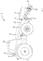
- Fig. 1 shows a schematic representation of an agricultural machine combination 1 with an agricultural tractor 2 from the side.
- a material tank 3 of a distribution machine is arranged on the front of the farm tractor 2.
- a material to be discharged is provided for the distribution machine, in which a distribution device, not shown to simplify the illustration, takes over the discharge of the material.
- the distribution device is usually arranged at the rear of the tractor 2, for example a distribution device for spreading a fertilizer material, a seed and / or a spray material.
- the distribution device can be accommodated on the farm tractor 2, for example, by means of a conventional three-point mounting.
- a feed line 4 is provided, which is coupled at the front to a material outlet 5 of the material tank 3 in order to receive the material to be spread from the material tank 3 and to transport it to a rear end 6 of the conveying line 4, from where it can reach the distribution device (via an additional pipe section, not shown).
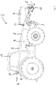
- Fig. 1 and 2 show 3 different height positions above the ground for the material tank. While the 3 in Fig. 1 is in a lowered position shows Fig. 2 a raised position of the material tank 3 Line pipe section 8 slidably added.
- the lifting of the material tank 3 causes the rigid pipe section 8 to pivot relative to the assembly area 9 and, at the same time, a displacement of the rear end 6 of the delivery line 4 to the rear.
- the rigid pipe section 8 of a fastening device 10 can slide or slide in the longitudinal direction of the rigid pipe section 8.
- the fastening device 10 or its assembly provides a point of rotation or rotation around which the rigid pipe section 8 can pivot. This makes it possible to make the delivery line 4 rigid at least between the material outlet 5 of the material tank 3 and the assembly area 9, in particular also in a kink area 11 is pivotally mounted to the direction of travel.
- the fastening device 10 is arranged on a driver's cab 13 of the farm tractor 2.
Landscapes
- Life Sciences & Earth Sciences (AREA)
- Soil Sciences (AREA)
- Environmental Sciences (AREA)
- Engineering & Computer Science (AREA)
- Insects & Arthropods (AREA)
- Pest Control & Pesticides (AREA)
- Wood Science & Technology (AREA)
- Zoology (AREA)
- Fertilizing (AREA)
Abstract
Description
- Die Erfindung betrifft eine landwirtschaftliche Maschinenkombination.
- Landwirtschaftliche Maschinenkombinationen mit einem Ackerschlepper und einer Verteilmaschine, die an dem Ackerschlepper angeordnet ist, dienen dazu, ein auszubringendes Material im Feldeinsatz über den Boden zu verteilen. Bei der Verteilmaschine kann es sich beispielsweise um einen Düngerstreuer, eine Sämaschine oder eine Sprühmaschine handeln. Auch Kombinationen solcher Verteilmaschinen können am Ackerschlepper vorgesehen sein. Es ist hierbei bekannt, das auszubringende Material in einem Materialtank bereitzustellen, der am Ackerschlepper frontseitig angeordnet ist. Das auszubringende Material wird über eine Förderleitung zur Verteileinrichtung der Verteilmaschine gebracht oder transportiert, um es dann mit der Verteileinrichtung auf den Boden auszubringen.
- Im Dokument
DE 10 2016 125 336 A1 ist eine landwirtschaftliche Maschinenkombination dieser Art offenbart. Auch im DokumentDE 10 2010 017 753 A1 ist eine landwirtschaftliche Maschinenkombination beschrieben, bei der das auszubringende Material aus einem am Ackerschlepper frontseitig angeordneten Materialtank über eine Förderleitung zur heckseitigen Verteileinrichtung transportiert wird. - Bei bekannten Maschinenkombinationen sind in der Förderleitung flexible Rohrabschnitte vorgesehen, um das Anheben und Absenken des Materialtanks zu ermöglichen.
- Aufgabe der Erfindung ist es, eine landwirtschaftliche Maschinenkombination mit einem Ackerschlepper und einer hieran gebildeten Verteilmaschine bereitzustellen, bei der Betriebsstörungen verbessert vermieden sind, insbesondere das auszubringende Material störungsfrei zwischen Materialtank und Verteileinrichtung transportiert werden kann.
- Zur Lösung der Aufgabe ist eine landwirtschaftliche Maschinenkombination nach dem unabhängigen Anspruch 1 geschaffen. Ausgestaltungen sind Gegenstand von abhängigen Unteransprüchen.
- Nach einem Aspekt ist eine landwirtschaftliche Maschinenkombination mit einem Ackerschlepper und einer Verteilmaschine geschaffen. Die Verteilmaschine weist Folgendes auf: einen Materialtank, der am Ackerschlepper frontseitig angeordnet und eingerichtet ist, ein zu verteilendes Material aufzunehmen; eine Verteileinrichtung, der am Ackerschlepper heckseitig angeordnet und eingerichtet ist, das zu verteilende Material auszubringen; und eine Förderleitung, die zwischen dem Materialtank und der Verteileinrichtung angeordnet und durch die hindurch das zu verteilende Material vom Materialtank zur Verteileinrichtung förderbar ist. Die landwirtschaftliche Maschinenkombination weist weiterhin eine Halte- und Hebeeinrichtung auf, mit der der Materialtank am Ackerschlepper frontseitig gehalten wird, derart, dass der Materialtank mittels der Halte- und Hebeeinrichtung in verschiedene Höhenstellung oberhalb des Bodens verlagerbar ist. Ein starrer Leitungsrohrabschnitt der Förderleitung ist mittels einer Befestigungseinrichtung in einem Montagebereich am Ackerschlepper befestigt, derart, dass der starre Leitungsrohrabschnitt relativ zum Montagebereich sowohl schwenkbar wie auch in Längsrichtung des starren Leitungsrohrabschnitts verschiebbar ist, wenn der Materialtank mittels der Halte- und Hebeeinrichtung zwischen verschiedenen Höhenstellungen verlagert wird.
- Die Förderleitung kann in verschiedenen Ausführungsformen aus einem Kunststoff- und / oder einem Metallmaterial bestehen.
- Mit Hilfe der vorgesehenen Lagerung oder Aufnahme des starren Leitungsrohrabschnitts der Förderleitung im Montagebereich am Ackerschlepper ist es ermöglicht, dass sich der starre Leitungsrohrabschnitt beim Anheben und beim Absenken des Materialtanks relativ zum Montagebereich verlagern kann, sowohl aufgrund des Schwenkens wie auch (zusätzlich) einer linearen Verschiebebewegung. Der starre Leitungsrohrabschnitt führt hierbei relativ zum Montagebereich eine Schwenkbewegung und eine Linearbewegung aus. Daher kann der Einsatz von flexiblen Rohrabschnitten im Bereich der Förderleitung minimiert werden oder ganz unterbleiben, so dass die Förderleitung frei von flexiblen Rohrabschnitten ausgebildet werden kann, was einen störungsfreien Transport des auszubringenden Materials durch die Förderleitung unterstützt.
- Der starre Leitungsrohrabschnitt kann mit einem der Förderleitung zugeordneten Materialausgang des Materialtanks starr verbunden sein. Die Förderleitung kann an dem Materialausgang des Materialtanks um eine Achse schwenkbar angeordnet sein, die im Wesentlichen senkrecht auf einer Öffnungsfläche des Materialausgangs steht. Eine solche Schwenkachse kann zum Beispiel quer zur Fahrtrichtung des Ackerschleppers verlaufen.
- Die Befestigungseinrichtung kann in einem Montagebereich an einer Fahrerkabine des Ackerschleppers angeordnet sein. Die Befestigungseinrichtung kann im Bereich eines heckseitigen Teils der Fahrkabine des Ackerschleppers angeordnet sein. Die Befestigungseinrichtung kann an einem Rahmen der Fahrerkabine montiert sein. Allgemein kann der Montagebereich in einem hinteren oder heckseitigen Abschnitt des Ackerschleppers vorgesehen sein, sei es an der Fahrerkabine oder einem anderen Bauteil des Ackerschleppers.
- Der starre Leitungsrohrabschnitt kann mit einem Knickabschnitt gebildet sein. Außerhalb des einen Knickabschnitts oder mehreren Knickabschnitten kann der starre Leitungsrohrabschnitt im Wesentlichen gerade verlaufen, also frei von gebogenen oder gekrümmten Rohrabschnitten sein.
- Der starre Leitungsrohrabschnitt kann einen Bereich der Förderleitung zwischen dem Materialausgang und dem Montagebereich im Wesentlichen vollständig erfassend ausgebildet sein. Bei dieser Ausgestaltung erstreckt sich der starre Leitungsrohrabschnitt zumindest zwischen dem Materialausgang und dem Montagebereich. Bei dieser oder anderen Ausgestaltungen kann sich der starre Leitungsrohrabschnitt in heckseitiger Richtung über den Montagebereich und die hier montieret Befestigungseinrichtung hinaus erstrecken, also hiervon ausgehend nach hinten vor- oder überstehen.
- Die Förderleitung kann zumindest entlang des starren Leitungsrohrabschnitts mit einer rutschfördernden oder -unterstützenden Innenoberfläche gebildet sein. Die Innenoberfläche kann hierbei als glatte Oberfläche ausgeführt sein. Insbesondere kann die rutschfördernde Innenoberfläche des starren Leitungsrohrabschnitts frei von gewellten Oberflächenabschnitten sein. Die rutschfördernde Innenoberfläche, insbesondere in einer glatten Ausführungsform, kann auch in einem oder mehreren Knickbereichen des starren Leitungsrohrabschnitts ausgebildet sein.
- Die Förderleitung kann zwischen dem Materialtank und der Verteileinrichtung mit einer rutschfördernden Innenoberfläche gebildet sein.
- Der starre Leitungsrohrabschnitt kann mit Rohrabschnitten mehrstückig gebildet sein, welche starr miteinander verbunden sind. Eine Verbindung zwischen benachbarten Rohrabschnitten des starren Leitungsrohrabschnitts kann zum Beispiel in einem Knickbereich vorgesehen sein. Die mehreren Rohrabschnitte können mittels einer Steckverbindung oder einer Schraubverbindung miteinander verbunden sein.
- Zwischen einem heckseitigen Ende des starren Leitungsrohrabschnitts und einem der Förderleitung zugeordneten Materialeingang der Verteilmaschine kann ein flexibler Leitungsrohrabschnitt der Förderleitung angeordnet sein. Der flexible Leitungsrohrabschnitt kann mit einer flexiblen Schlauchleitung gebildet sein. Im Bereich des flexiblen Leitungsrohrabschnitts kann eine innere Oberfläche im Wesentlichen glatt ausgeführt sein, insbesondere frei von gewellten Abschnitten sein. Alternativ zum flexiblen Leitungsrohrabschnitt kann die Verbindung zum Materialeingang der Verteilmaschine hin mit einem weiteren starren Leitungsrohrabschnitt gebildet sein.
- Der starre Leitungsrohrabschnitt kann mit einem vom Materialausgang des Materialtanks ausgehenden tankseitigen starren Leitungsrohrabschnitt, welcher an dem Materialtank und / oder einem Tragrahmen des Materialtanks gehalten wird, und einem hiermit starr verbundenen schlepperseitigen starren Anschlussrohrabschnitt gebildet sein, welcher mittels der Befestigungseinrichtung am Ackerschlepper gehalten wird. Der tankseitige starre Leitungsrohrabschnitt und der schlepperseitige starre Anschlussrohrabschnitt können in einer Ausführung über einen Knickbereich miteinander verbunden sein. Der schlepperseitige starre Anschlussrohrabschnitt kann sich bis zum Montagebereich hin erstrecken, wahlweise darüber hinaus.
- Die Verteilmaschine kann einer Maschinenart aus der folgenden Gruppe entsprechend ausgebildet sein: Düngerstreuer, Sämaschine und Sprühmaschine. Je nach Ausgestaltung der Verteilmaschine ist die Verteileinrichtung eingerichtet, ein entsprechendes Material auszubringen. Insbesondere sind an der Verteileinrichtung entsprechende Ausbringorgane vorgesehen, zum Beispiel Düngerstreuer oder Sprühdüsen.
- Mit Hilfe der vorgeschlagenen landwirtschaftlichen Maschinenkombination ist ein verfahren zum Fördern eines auszubringenden Materials aus dem frontseitig am Ackerschlepper angeordneten Materialtank zu einer Verteileinrichtung einer Verteilmaschine ausführbar, bei dem das auszubringende Material entlang eines starren Leitungsrohrabschnitts einer Förderleitung transportiert wird, welcher mittels einer Befestigungseinrichtung in einem Montagebereich am Ackerschlepper befestigt ist, derart, dass der starre Leitungsrohrabschnitt relativ zum Montagebereich sowohl geschwenkt wie auch in Längsrichtung des starren Leitungsrohrabschnitts verschoben werden kann, wenn der Materialtank mittels der Halte- und Hebeeinrichtung zwischen verschiedenen Höhenstellungen verlagert wird.
- Auch ist ein hierzu ergänzendes oder alternatives Verfahren ausführbar, bei dem der starre Leitungsrohrabschnitt der Förderleitung relativ zum Montagebereich oder einem anderen Bezugspunkt am Ackerschlepper sowohl geschwenkt wie auch in Längsrichtung des starren Leitungsrohrabschnitts verschoben wird, wenn der Materialtank mittels der Halte- und Hebeeinrichtung zwischen verschiedenen Höhenstellungen verlagert wird.
- Im Folgenden werden weitere Ausführungsbeispiele unter Bezugnahme auf Figuren einer Zeichnung näher erläutert. In den Figuren zeigen:
- Fig. 1
- eine schematische Darstellung einer landwirtschaftlichen Maschinenkombination mit einem Ackerschlepper und einem Materialtank einer Verteilmaschine, der frontseitig an dem Ackerschlepper angeordnet ist, wobei der Materialtank in einer abgesenkten Stellung gezeigt ist; und
- Fig. 2
- eine schematische Darstellung der landwirtschaftlichen Maschinenkombination aus
Fig. 1 , wobei der Materialtank in einer angehobenen Stellung gezeigt ist. -
Fig. 1 zeigt eine schematische Darstellung einer landwirtschaftlichen Maschinenkombination 1 mit einem Ackerschlepper 2 von der Seite. An dem Ackerschlepper 2 ist frontseitig ein Materialtank 3 einer Verteilmaschine angeordnet. Mit Hilfe des Materialtanks 3 wird ein auszubringendes Material für die Verteilmaschine bereitgestellt, bei der eine zur Vereinfachung der Darstellung nicht gezeigte Verteileinrichtung das Ausbringen des Materials übernimmt. Üblicherweise ist die Verteileinrichtung heckseitig am Ackerschlepper 2 angeordnet, beispielsweise eine Verteileinrichtung zum Ausbringen eines Düngermaterials, eines Saatguts und / oder eines Sprühmaterials. Hierbei kann die Verteileinrichtung zum Beispiel mittels einer üblichen Dreipunkt-Lagerung am Ackerschlepper 2 aufgenommen sein. - Um das auszubringende Material aus dem frontseitig am Ackerschlepper 2 angeordneten Materialtank 3 zur rück- oder heckseitig angeordneten Verteileinrichtung zu bringen, ist eine Förderleitung 4 vorgesehen, die frontseitig an einen Materialausgang 5 des Materialtanks 3 koppelt, um hierüber das auszubringende Material aus dem Materialtank 3 aufzunehmen und es zu einem heckseitigen Ende 6 der Förderleitung 4 zu transportieren, von wo aus es (über einen zusätzlichen, nicht dargestellten Rohrabschnitt) zur Verteileinrichtung gelangen kann.
-
Fig. 1 und2 zeigen für den Materialtank 3 unterschiedliche Höhenstellungen über dem Boden. Während der Materialtank 3 inFig. 1 in einer abgesenkten Stellung ist, zeigtFig. 2 eine angehobene Stellung des Materialtanks 3. Um eine solche Verlagerung des Materialtanks 3 mittels einer am Ackerschlepper 2 frontseitig vorgesehenen Halte- und Hebeeinrichtung 7 zu ermöglichen, ist ein starrer Leitungsrohrabschnitt 8 der Förderleitung 4 in einem Montagebereich 9 am Ackerschlepper 2 schwenkbar und in Längsrichtung des starren Leitungsrohrabschnitts 8 verschiebbar aufgenommen. - Gemäß den
Fig. 1 und2 bewirkt das Anheben des Materialtanks 3 ein Schwenken des starren Rohrleitungsabschnitts 8 relativ zum Montagebereich 9 sowie gleichzeitig ein Verschieben des heckseitigen Endes 6 der Förderleitung 4 nach hinten. Hierzu kann der starre Rohrleitungsabschnitt 8 einer Befestigungseinrichtung 10 in Längsrichtung des starren Rohrleitungsabschnitts 8 gleiten oder rutschen. Gleichzeitig stellt die Befestigungseinrichtung 10 oder deren Montage einen Dreh- oder Rotationspunkt zur Verfügung, um den sich der starre Rohrleitungsabschnitt 8 verschwenken kann. Dieses ermöglicht es, die Förderleitung 4 zumindest zwischen dem Materialausgang 5 des Materialtanks 3 und dem Montagebereich 9 starr auszubilden, insbesondere auch in einem Knickbereich 11. Hierbei kann vorgesehen sein, dass ein frontseitiges Ende 12 der Förderleitung 4 in dem Materialausgang 5 um eine Achse quer zur Fahrtrichtung schwenkbar gelagert ist. - Bei der gezeigten Ausführung ist die Befestigungseinrichtung 10 an einer Fahrerkabine 13 des Ackerschleppers 2 angeordnet.
- Die in der vorstehenden Beschreibung, den Ansprüchen sowie der Zeichnung offenbarten Merkmale können sowohl einzeln als auch in beliebiger Kombination für die Verwirklichung der verschiedenen Ausführungen von Bedeutung sein.
Claims (11)
- Landwirtschaftliche Maschinenkombination (1), mit:- einem Ackerschlepper (2);- einer Verteilmaschine, aufweisend- einen Materialtank (3), der am Ackerschlepper (2) frontseitig angeordnet und eingerichtet ist, ein zu verteilendes Material aufzunehmen;- eine Verteileinrichtung, der am Ackerschlepper (2) heckseitig angeordnet und eingerichtet ist, das zu verteilende Material auszubringen; und- eine Förderleitung (4), die zwischen dem Materialtank (3) und der Verteileinrichtung angeordnet und durch die hindurch das zu verteilende Material vom Materialtank (3) zur Verteileinrichtung förderbar ist; und- einer Halte- und Hebeeinrichtung (7), mit der der Materialtank (3) am Ackerschlepper (2) frontseitig gehalten wird, derart, dass der Materialtank (3) mittels der Halte- und Hebeeinrichtung (7) in verschiedene Höhenstellung oberhalb des Bodens verlagerbar ist;wobei ein starrer Leitungsrohrabschnitt (8) der Förderleitung (4) mittels einer Befestigungseinrichtung (10) in einem Montagebereich (9) am Ackerschlepper (2) befestigt ist, derart, dass der starre Leitungsrohrabschnitt (8) relativ zum Montagebereich (9) sowohl schwenkbar wie auch in Längsrichtung des starren Leitungsrohrabschnitts (8) verschiebbar ist, wenn der Materialtank (3) mittels der Halte- und Hebeeinrichtung (7) zwischen verschiedenen Höhenstellungen verlagert wird.
- Landwirtschaftliche Maschinenkombination (1) nach Anspruch 1, dadurch gekennzeichnet, dass der starre Leitungsrohrabschnitt (8) mit einem der Förderleitung (4) zugeordneten Materialausgang (5) des Materialtanks (3) starr verbunden ist.
- Landwirtschaftliche Maschinenkombination (1) nach Anspruch 1 oder 2, dadurch gekennzeichnet, dass die Befestigungseinrichtung (10) in einem Montagebereich (9) an einer Fahrerkabine (13) des Ackerschleppers (2) angeordnet ist.
- Landwirtschaftliche Maschinenkombination (1) nach mindestens einem der vorangehenden Ansprüche, dadurch gekennzeichnet, dass der starre Leitungsrohrabschnitt (8) mit einem Knickabschnitt (11) gebildet ist.
- Landwirtschaftliche Maschinenkombination (1) nach mindestens einem der vorangehenden Ansprüche, dadurch gekennzeichnet, dass der starre Leitungsrohrabschnitt (8) einen Bereich der Förderleitung (4) zwischen dem Materialausgang und dem Montagebereich (9) vollständig erfassend ausgebildet ist.
- Landwirtschaftliche Maschinenkombination (1) nach mindestens einem der vorangehenden Ansprüche, dadurch gekennzeichnet, dass die Förderleitung (4) zumindest entlang des starren Leitungsrohrabschnitts (8) mit einer rutschfördernden Innenoberfläche gebildet ist.
- Landwirtschaftliche Maschinenkombination (1) nach Anspruch 6, dadurch gekennzeichnet, dass die Förderleitung (4) zwischen dem Materialtank (3) und der Verteileinrichtung mit einer rutschfördernden Innenoberfläche gebildet ist.
- Landwirtschaftliche Maschinenkombination (1) nach mindestens einem der vorangehenden Ansprüche, dadurch gekennzeichnet, dass der starre Leitungsrohrabschnitt (8) mit Rohrabschnitten mehrstückig gebildet ist, die starr miteinander verbunden sind.
- Landwirtschaftliche Maschinenkombination (1) nach mindestens einem der vorangehenden Ansprüche, dadurch gekennzeichnet, dass zwischen einem heckseitigen Ende (6) des starren Leitungsrohrabschnitts (8) und einem der Förderleitung (4) zugeordneten Materialeingang der Verteilmaschine ein flexibler Leitungsrohrabschnitt der Förderleitung (4) angeordnet ist.
- Landwirtschaftliche Maschinenkombination (1) nach mindestens einem der vorangehenden Ansprüche, dadurch gekennzeichnet, dass der starre Leitungsrohrabschnitt (8) gebildet ist mit- einem vom Materialausgang (5) des Materialtanks (3) ausgehenden tankseitigen starren Leitungsrohrabschnitt, welcher an dem Materialtank (3) und / oder einem Tragrahmen des Materialtanks (3) gehalten wird, und- einem hiermit starr verbundenen schlepperseitigen starren Anschlussrohrabschnitt, welcher mittels der Befestigungseinrichtung (10) am Ackerschlepper (2) gehalten wird.
- Landwirtschaftliche Maschinenkombination (1) nach mindestens einem der vorangehenden Ansprüche, dadurch gekennzeichnet, dass die Verteilmaschine von einer Maschinenart aus der folgenden Gruppe ist: Düngerstreuer, Sämaschine und Sprühmaschine.
Priority Applications (5)
| Application Number | Priority Date | Filing Date | Title |
|---|---|---|---|
| PL20159066.8T PL3868204T3 (pl) | 2020-02-24 | 2020-02-24 | Rolnicze połączenie maszynowe |
| HUE20159066A HUE064616T2 (hu) | 2020-02-24 | 2020-02-24 | Mezõgazdasági gépkombináció |
| EP20159066.8A EP3868204B1 (de) | 2020-02-24 | 2020-02-24 | Landwirtschaftliche maschinenkombination |
| ES20159066T ES2962839T3 (es) | 2020-02-24 | 2020-02-24 | Combinación de máquinas agrícolas |
| PCT/EP2021/053999 WO2021170480A1 (de) | 2020-02-24 | 2021-02-18 | Landwirtschaftliche maschinenkombination |
Applications Claiming Priority (1)
| Application Number | Priority Date | Filing Date | Title |
|---|---|---|---|
| EP20159066.8A EP3868204B1 (de) | 2020-02-24 | 2020-02-24 | Landwirtschaftliche maschinenkombination |
Publications (3)
| Publication Number | Publication Date |
|---|---|
| EP3868204A1 true EP3868204A1 (de) | 2021-08-25 |
| EP3868204C0 EP3868204C0 (de) | 2023-10-11 |
| EP3868204B1 EP3868204B1 (de) | 2023-10-11 |
Family
ID=69845053
Family Applications (1)
| Application Number | Title | Priority Date | Filing Date |
|---|---|---|---|
| EP20159066.8A Active EP3868204B1 (de) | 2020-02-24 | 2020-02-24 | Landwirtschaftliche maschinenkombination |
Country Status (5)
| Country | Link |
|---|---|
| EP (1) | EP3868204B1 (de) |
| ES (1) | ES2962839T3 (de) |
| HU (1) | HUE064616T2 (de) |
| PL (1) | PL3868204T3 (de) |
| WO (1) | WO2021170480A1 (de) |
Citations (4)
| Publication number | Priority date | Publication date | Assignee | Title |
|---|---|---|---|---|
| DE3540198A1 (de) * | 1985-11-13 | 1987-05-21 | Amazonen Werke Dreyer H | Zusatztank zum nachfuellen von vorratsbehaeltern bei landwirtschaftlichen verteilmaschinen |
| DE202010007812U1 (de) * | 2010-06-10 | 2010-08-26 | Rietze, Martin | Ackerschlepper mit einem Frontlader |
| DE102010017753A1 (de) | 2010-07-06 | 2012-01-12 | Amazonen-Werke H. Dreyer Gmbh & Co. Kg | Landwirtschaftliche Vorrichtung |
| DE102016125336A1 (de) | 2016-12-22 | 2018-06-28 | Amazonen-Werke H. Dreyer Gmbh & Co. Kg | Landwirtschaftliche Kombination und Verfahren zum Betreiben der Kombination |
-
2020
- 2020-02-24 HU HUE20159066A patent/HUE064616T2/hu unknown
- 2020-02-24 ES ES20159066T patent/ES2962839T3/es active Active
- 2020-02-24 PL PL20159066.8T patent/PL3868204T3/pl unknown
- 2020-02-24 EP EP20159066.8A patent/EP3868204B1/de active Active
-
2021
- 2021-02-18 WO PCT/EP2021/053999 patent/WO2021170480A1/de not_active Ceased
Patent Citations (4)
| Publication number | Priority date | Publication date | Assignee | Title |
|---|---|---|---|---|
| DE3540198A1 (de) * | 1985-11-13 | 1987-05-21 | Amazonen Werke Dreyer H | Zusatztank zum nachfuellen von vorratsbehaeltern bei landwirtschaftlichen verteilmaschinen |
| DE202010007812U1 (de) * | 2010-06-10 | 2010-08-26 | Rietze, Martin | Ackerschlepper mit einem Frontlader |
| DE102010017753A1 (de) | 2010-07-06 | 2012-01-12 | Amazonen-Werke H. Dreyer Gmbh & Co. Kg | Landwirtschaftliche Vorrichtung |
| DE102016125336A1 (de) | 2016-12-22 | 2018-06-28 | Amazonen-Werke H. Dreyer Gmbh & Co. Kg | Landwirtschaftliche Kombination und Verfahren zum Betreiben der Kombination |
Also Published As
| Publication number | Publication date |
|---|---|
| PL3868204T3 (pl) | 2024-02-12 |
| WO2021170480A1 (de) | 2021-09-02 |
| EP3868204C0 (de) | 2023-10-11 |
| EP3868204B1 (de) | 2023-10-11 |
| HUE064616T2 (hu) | 2024-04-28 |
| ES2962839T3 (es) | 2024-03-21 |
Similar Documents
| Publication | Publication Date | Title |
|---|---|---|
| EP0574740A1 (de) | Vorrichtung zum Ausbringen von Behandlungsflüssigkeit auf Pflanzenreihen | |
| EP2289300A1 (de) | Förderanordnung für Wirtschaftsdünger | |
| EP1974596A1 (de) | Säscharanordnung | |
| EP3320765B1 (de) | Scheibenschlitzeinheit für eine gülleausbringvorrichtung | |
| EP0163154A2 (de) | Spritzvorrichtung zum Ausbringen von flüssigen Spritzmitteln | |
| EP3868204B1 (de) | Landwirtschaftliche maschinenkombination | |
| DE19640037C2 (de) | Gülleausbringfahrzeug | |
| DE10339162B4 (de) | Gülleausbringfahrzeug | |
| EP3957148B1 (de) | Vorrichtung zur verteilung von gülle | |
| DE19709065A1 (de) | Gülleausbring-Fahrzeug | |
| EP0746970A2 (de) | Gülleausbringvorrichtung für Güllefahrzeuge | |
| EP4248727A1 (de) | Gülleausbringungsvorrichtung | |
| DE102012101191A1 (de) | Verteilmaschine, insbesondere Pflanzenschutzspritze | |
| EP2100493B1 (de) | Gülleverteiler-Fahrzeug | |
| DE102011101144A1 (de) | Ackerschlepper mit einem Frontlader | |
| DE102017125198B4 (de) | Verteilergestänge für eine Pflanzenschutzspritze | |
| EP3320764B1 (de) | Säreihe für eine sämaschine | |
| EP2319304A1 (de) | Spritzeinrichtung | |
| DE4137282C2 (de) | Schlepper mit nach vorn abfallender Motorhaube | |
| DE69911516T2 (de) | Sämaschine | |
| DE202018105769U1 (de) | Düngemittel-Ausbringvorrichtung mit Parallelführung und Hubvorrichtung | |
| AT523682B1 (de) | Transporteinrichtung und Dosiermodul | |
| DE102023120172A1 (de) | Düngemittelverteiler zur bodennahen Ausbringung von Düngemitteln | |
| DE3512226A1 (de) | Duengeverteiler | |
| DE3145113C2 (de) | Tankwagen zum Aufbringen von insbesondere Gülle auf landwirtschaftlich genutzte Bodenflächen |
Legal Events
| Date | Code | Title | Description |
|---|---|---|---|
| PUAI | Public reference made under article 153(3) epc to a published international application that has entered the european phase |
Free format text: ORIGINAL CODE: 0009012 |
|
| STAA | Information on the status of an ep patent application or granted ep patent |
Free format text: STATUS: REQUEST FOR EXAMINATION WAS MADE |
|
| 17P | Request for examination filed |
Effective date: 20210226 |
|
| AK | Designated contracting states |
Kind code of ref document: A1 Designated state(s): AL AT BE BG CH CY CZ DE DK EE ES FI FR GB GR HR HU IE IS IT LI LT LU LV MC MK MT NL NO PL PT RO RS SE SI SK SM TR |
|
| RAP1 | Party data changed (applicant data changed or rights of an application transferred) |
Owner name: KVERNELAND GROUP SOEST GMBH |
|
| RIC1 | Information provided on ipc code assigned before grant |
Ipc: A01C 15/00 20060101ALI20230316BHEP Ipc: A01C 7/08 20060101ALI20230316BHEP Ipc: A01M 7/00 20060101AFI20230316BHEP |
|
| GRAP | Despatch of communication of intention to grant a patent |
Free format text: ORIGINAL CODE: EPIDOSNIGR1 |
|
| STAA | Information on the status of an ep patent application or granted ep patent |
Free format text: STATUS: GRANT OF PATENT IS INTENDED |
|
| INTG | Intention to grant announced |
Effective date: 20230504 |
|
| P01 | Opt-out of the competence of the unified patent court (upc) registered |
Effective date: 20230525 |
|
| GRAS | Grant fee paid |
Free format text: ORIGINAL CODE: EPIDOSNIGR3 |
|
| GRAA | (expected) grant |
Free format text: ORIGINAL CODE: 0009210 |
|
| STAA | Information on the status of an ep patent application or granted ep patent |
Free format text: STATUS: THE PATENT HAS BEEN GRANTED |
|
| AK | Designated contracting states |
Kind code of ref document: B1 Designated state(s): AL AT BE BG CH CY CZ DE DK EE ES FI FR GB GR HR HU IE IS IT LI LT LU LV MC MK MT NL NO PL PT RO RS SE SI SK SM TR |
|
| REG | Reference to a national code |
Ref country code: GB Ref legal event code: FG4D Free format text: NOT ENGLISH |
|
| REG | Reference to a national code |
Ref country code: CH Ref legal event code: EP |
|
| REG | Reference to a national code |
Ref country code: DE Ref legal event code: R096 Ref document number: 502020005570 Country of ref document: DE |
|
| REG | Reference to a national code |
Ref country code: IE Ref legal event code: FG4D Free format text: LANGUAGE OF EP DOCUMENT: GERMAN |
|
| REG | Reference to a national code |
Ref country code: RO Ref legal event code: EPE |
|
| P04 | Withdrawal of opt-out of the competence of the unified patent court (upc) registered |
Effective date: 20231030 |
|
| U01 | Request for unitary effect filed |
Effective date: 20231027 |
|
| U07 | Unitary effect registered |
Designated state(s): AT BE BG DE DK EE FI FR IT LT LU LV MT NL PT SE SI Effective date: 20231103 |
|
| REG | Reference to a national code |
Ref country code: ES Ref legal event code: FG2A Ref document number: 2962839 Country of ref document: ES Kind code of ref document: T3 Effective date: 20240321 |
|
| U20 | Renewal fee for the european patent with unitary effect paid |
Year of fee payment: 5 Effective date: 20240222 |
|
| PG25 | Lapsed in a contracting state [announced via postgrant information from national office to epo] |
Ref country code: GR Free format text: LAPSE BECAUSE OF FAILURE TO SUBMIT A TRANSLATION OF THE DESCRIPTION OR TO PAY THE FEE WITHIN THE PRESCRIBED TIME-LIMIT Effective date: 20240112 |
|
| PG25 | Lapsed in a contracting state [announced via postgrant information from national office to epo] |
Ref country code: IS Free format text: LAPSE BECAUSE OF FAILURE TO SUBMIT A TRANSLATION OF THE DESCRIPTION OR TO PAY THE FEE WITHIN THE PRESCRIBED TIME-LIMIT Effective date: 20240211 |
|
| REG | Reference to a national code |
Ref country code: HU Ref legal event code: AG4A Ref document number: E064616 Country of ref document: HU |
|
| PG25 | Lapsed in a contracting state [announced via postgrant information from national office to epo] |
Ref country code: IS Free format text: LAPSE BECAUSE OF FAILURE TO SUBMIT A TRANSLATION OF THE DESCRIPTION OR TO PAY THE FEE WITHIN THE PRESCRIBED TIME-LIMIT Effective date: 20240211 Ref country code: GR Free format text: LAPSE BECAUSE OF FAILURE TO SUBMIT A TRANSLATION OF THE DESCRIPTION OR TO PAY THE FEE WITHIN THE PRESCRIBED TIME-LIMIT Effective date: 20240112 |
|
| PG25 | Lapsed in a contracting state [announced via postgrant information from national office to epo] |
Ref country code: RS Free format text: LAPSE BECAUSE OF FAILURE TO SUBMIT A TRANSLATION OF THE DESCRIPTION OR TO PAY THE FEE WITHIN THE PRESCRIBED TIME-LIMIT Effective date: 20231011 Ref country code: NO Free format text: LAPSE BECAUSE OF FAILURE TO SUBMIT A TRANSLATION OF THE DESCRIPTION OR TO PAY THE FEE WITHIN THE PRESCRIBED TIME-LIMIT Effective date: 20240111 Ref country code: HR Free format text: LAPSE BECAUSE OF FAILURE TO SUBMIT A TRANSLATION OF THE DESCRIPTION OR TO PAY THE FEE WITHIN THE PRESCRIBED TIME-LIMIT Effective date: 20231011 |
|
| REG | Reference to a national code |
Ref country code: DE Ref legal event code: R097 Ref document number: 502020005570 Country of ref document: DE |
|
| PG25 | Lapsed in a contracting state [announced via postgrant information from national office to epo] |
Ref country code: SK Free format text: LAPSE BECAUSE OF FAILURE TO SUBMIT A TRANSLATION OF THE DESCRIPTION OR TO PAY THE FEE WITHIN THE PRESCRIBED TIME-LIMIT Effective date: 20231011 |
|
| PG25 | Lapsed in a contracting state [announced via postgrant information from national office to epo] |
Ref country code: SM Free format text: LAPSE BECAUSE OF FAILURE TO SUBMIT A TRANSLATION OF THE DESCRIPTION OR TO PAY THE FEE WITHIN THE PRESCRIBED TIME-LIMIT Effective date: 20231011 Ref country code: SK Free format text: LAPSE BECAUSE OF FAILURE TO SUBMIT A TRANSLATION OF THE DESCRIPTION OR TO PAY THE FEE WITHIN THE PRESCRIBED TIME-LIMIT Effective date: 20231011 |
|
| PLBE | No opposition filed within time limit |
Free format text: ORIGINAL CODE: 0009261 |
|
| STAA | Information on the status of an ep patent application or granted ep patent |
Free format text: STATUS: NO OPPOSITION FILED WITHIN TIME LIMIT |
|
| 26N | No opposition filed |
Effective date: 20240712 |
|
| PG25 | Lapsed in a contracting state [announced via postgrant information from national office to epo] |
Ref country code: MC Free format text: LAPSE BECAUSE OF FAILURE TO SUBMIT A TRANSLATION OF THE DESCRIPTION OR TO PAY THE FEE WITHIN THE PRESCRIBED TIME-LIMIT Effective date: 20231011 |
|
| REG | Reference to a national code |
Ref country code: CH Ref legal event code: PL |
|
| PG25 | Lapsed in a contracting state [announced via postgrant information from national office to epo] |
Ref country code: CH Free format text: LAPSE BECAUSE OF NON-PAYMENT OF DUE FEES Effective date: 20240229 |
|
| PG25 | Lapsed in a contracting state [announced via postgrant information from national office to epo] |
Ref country code: CH Free format text: LAPSE BECAUSE OF NON-PAYMENT OF DUE FEES Effective date: 20240229 |
|
| P05 | Withdrawal of opt-out of the competence of the unified patent court (upc) changed |
Free format text: CASE NUMBER: APP_584236/2023 Effective date: 20231103 |
|
| U20 | Renewal fee for the european patent with unitary effect paid |
Year of fee payment: 6 Effective date: 20250221 |
|
| PGFP | Annual fee paid to national office [announced via postgrant information from national office to epo] |
Ref country code: ES Payment date: 20250331 Year of fee payment: 6 |
|
| PG25 | Lapsed in a contracting state [announced via postgrant information from national office to epo] |
Ref country code: CY Free format text: LAPSE BECAUSE OF FAILURE TO SUBMIT A TRANSLATION OF THE DESCRIPTION OR TO PAY THE FEE WITHIN THE PRESCRIBED TIME-LIMIT; INVALID AB INITIO Effective date: 20200224 |
|
| PG25 | Lapsed in a contracting state [announced via postgrant information from national office to epo] |
Ref country code: TR Free format text: LAPSE BECAUSE OF FAILURE TO SUBMIT A TRANSLATION OF THE DESCRIPTION OR TO PAY THE FEE WITHIN THE PRESCRIBED TIME-LIMIT Effective date: 20231011 |
|
| PGFP | Annual fee paid to national office [announced via postgrant information from national office to epo] |
Ref country code: HU Payment date: 20260220 Year of fee payment: 7 |
|
| U20 | Renewal fee for the european patent with unitary effect paid |
Year of fee payment: 7 Effective date: 20260225 |
|
| PGFP | Annual fee paid to national office [announced via postgrant information from national office to epo] |
Ref country code: GB Payment date: 20260220 Year of fee payment: 7 |
|
| PGFP | Annual fee paid to national office [announced via postgrant information from national office to epo] |
Ref country code: IE Payment date: 20260218 Year of fee payment: 7 |
|
| PGFP | Annual fee paid to national office [announced via postgrant information from national office to epo] |
Ref country code: RO Payment date: 20260218 Year of fee payment: 7 |
|
| PGFP | Annual fee paid to national office [announced via postgrant information from national office to epo] |
Ref country code: CZ Payment date: 20260217 Year of fee payment: 7 |
|
| PGFP | Annual fee paid to national office [announced via postgrant information from national office to epo] |
Ref country code: PL Payment date: 20260213 Year of fee payment: 7 |