EP3868480B1 - Spender und düse zum ausbringen einer mischung aus gas und pastenmaterial und mechanische schäumvorrichtung - Google Patents
Spender und düse zum ausbringen einer mischung aus gas und pastenmaterial und mechanische schäumvorrichtung Download PDFInfo
- Publication number
- EP3868480B1 EP3868480B1 EP19861262.4A EP19861262A EP3868480B1 EP 3868480 B1 EP3868480 B1 EP 3868480B1 EP 19861262 A EP19861262 A EP 19861262A EP 3868480 B1 EP3868480 B1 EP 3868480B1
- Authority
- EP
- European Patent Office
- Prior art keywords
- gas
- tip end
- mixture
- dispenser
- needle
- Prior art date
- Legal status (The legal status is an assumption and is not a legal conclusion. Google has not performed a legal analysis and makes no representation as to the accuracy of the status listed.)
- Active
Links
Images




Classifications
-
- B—PERFORMING OPERATIONS; TRANSPORTING
- B05—SPRAYING OR ATOMISING IN GENERAL; APPLYING FLUENT MATERIALS TO SURFACES, IN GENERAL
- B05C—APPARATUS FOR APPLYING FLUENT MATERIALS TO SURFACES, IN GENERAL
- B05C5/00—Apparatus in which liquid or other fluent material is projected, poured or allowed to flow on to the surface of the work
- B05C5/02—Apparatus in which liquid or other fluent material is projected, poured or allowed to flow on to the surface of the work the liquid or other fluent material being discharged through an outlet orifice by pressure, e.g. from an outlet device in contact or almost in contact, with the work
- B05C5/0225—Apparatus in which liquid or other fluent material is projected, poured or allowed to flow on to the surface of the work the liquid or other fluent material being discharged through an outlet orifice by pressure, e.g. from an outlet device in contact or almost in contact, with the work characterised by flow controlling means, e.g. valves, located proximate the outlet
- B05C5/0237—Fluid actuated valves
-
- B—PERFORMING OPERATIONS; TRANSPORTING
- B05—SPRAYING OR ATOMISING IN GENERAL; APPLYING FLUENT MATERIALS TO SURFACES, IN GENERAL
- B05B—SPRAYING APPARATUS; ATOMISING APPARATUS; NOZZLES
- B05B7/00—Spraying apparatus for discharge of liquids or other fluent materials from two or more sources, e.g. of liquid and air, of powder and gas
- B05B7/0018—Spraying apparatus for discharge of liquids or other fluent materials from two or more sources, e.g. of liquid and air, of powder and gas with devices for making foam
- B05B7/0025—Spraying apparatus for discharge of liquids or other fluent materials from two or more sources, e.g. of liquid and air, of powder and gas with devices for making foam with a compressed gas supply
- B05B7/0031—Spraying apparatus for discharge of liquids or other fluent materials from two or more sources, e.g. of liquid and air, of powder and gas with devices for making foam with a compressed gas supply with disturbing means promoting mixing, e.g. balls, crowns
-
- B—PERFORMING OPERATIONS; TRANSPORTING
- B05—SPRAYING OR ATOMISING IN GENERAL; APPLYING FLUENT MATERIALS TO SURFACES, IN GENERAL
- B05B—SPRAYING APPARATUS; ATOMISING APPARATUS; NOZZLES
- B05B12/00—Arrangements for controlling delivery; Arrangements for controlling the spray area
- B05B12/004—Arrangements for controlling delivery; Arrangements for controlling the spray area comprising sensors for monitoring the delivery, e.g. by displaying the sensed value or generating an alarm
- B05B12/006—Pressure or flow rate sensors
- B05B12/008—Pressure or flow rate sensors integrated in or attached to a discharge apparatus, e.g. a spray gun
-
- B—PERFORMING OPERATIONS; TRANSPORTING
- B05—SPRAYING OR ATOMISING IN GENERAL; APPLYING FLUENT MATERIALS TO SURFACES, IN GENERAL
- B05B—SPRAYING APPARATUS; ATOMISING APPARATUS; NOZZLES
- B05B7/00—Spraying apparatus for discharge of liquids or other fluent materials from two or more sources, e.g. of liquid and air, of powder and gas
- B05B7/14—Spraying apparatus for discharge of liquids or other fluent materials from two or more sources, e.g. of liquid and air, of powder and gas designed for spraying particulate materials
- B05B7/1481—Spray pistols or apparatus for discharging particulate material
-
- B—PERFORMING OPERATIONS; TRANSPORTING
- B05—SPRAYING OR ATOMISING IN GENERAL; APPLYING FLUENT MATERIALS TO SURFACES, IN GENERAL
- B05C—APPARATUS FOR APPLYING FLUENT MATERIALS TO SURFACES, IN GENERAL
- B05C11/00—Component parts, details or accessories not specifically provided for in groups B05C1/00 - B05C9/00
- B05C11/10—Storage, supply or control of liquid or other fluent material; Recovery of excess liquid or other fluent material
- B05C11/1036—Means for supplying a selected one of a plurality of liquids or other fluent materials, or several in selected proportions, to the applying apparatus
-
- B—PERFORMING OPERATIONS; TRANSPORTING
- B29—WORKING OF PLASTICS; WORKING OF SUBSTANCES IN A PLASTIC STATE IN GENERAL
- B29B—PREPARATION OR PRETREATMENT OF THE MATERIAL TO BE SHAPED; MAKING GRANULES OR PREFORMS; RECOVERY OF PLASTICS OR OTHER CONSTITUENTS OF WASTE MATERIAL CONTAINING PLASTICS
- B29B7/00—Mixing; Kneading
- B29B7/30—Mixing; Kneading continuous, with mechanical mixing or kneading devices
- B29B7/58—Component parts, details or accessories; Auxiliary operations
- B29B7/72—Measuring, controlling or regulating
- B29B7/726—Measuring properties of mixture, e.g. temperature or density
-
- B—PERFORMING OPERATIONS; TRANSPORTING
- B29—WORKING OF PLASTICS; WORKING OF SUBSTANCES IN A PLASTIC STATE IN GENERAL
- B29B—PREPARATION OR PRETREATMENT OF THE MATERIAL TO BE SHAPED; MAKING GRANULES OR PREFORMS; RECOVERY OF PLASTICS OR OTHER CONSTITUENTS OF WASTE MATERIAL CONTAINING PLASTICS
- B29B7/00—Mixing; Kneading
- B29B7/30—Mixing; Kneading continuous, with mechanical mixing or kneading devices
- B29B7/58—Component parts, details or accessories; Auxiliary operations
- B29B7/72—Measuring, controlling or regulating
- B29B7/728—Measuring data of the driving system, e.g. torque, speed, power, vibration
-
- B—PERFORMING OPERATIONS; TRANSPORTING
- B29—WORKING OF PLASTICS; WORKING OF SUBSTANCES IN A PLASTIC STATE IN GENERAL
- B29B—PREPARATION OR PRETREATMENT OF THE MATERIAL TO BE SHAPED; MAKING GRANULES OR PREFORMS; RECOVERY OF PLASTICS OR OTHER CONSTITUENTS OF WASTE MATERIAL CONTAINING PLASTICS
- B29B7/00—Mixing; Kneading
- B29B7/74—Mixing; Kneading using other mixers or combinations of mixers, e.g. of dissimilar mixers ; Plant
- B29B7/7404—Mixing devices specially adapted for foamable substances
- B29B7/7409—Mixing devices specially adapted for foamable substances with supply of gas
-
- B—PERFORMING OPERATIONS; TRANSPORTING
- B29—WORKING OF PLASTICS; WORKING OF SUBSTANCES IN A PLASTIC STATE IN GENERAL
- B29B—PREPARATION OR PRETREATMENT OF THE MATERIAL TO BE SHAPED; MAKING GRANULES OR PREFORMS; RECOVERY OF PLASTICS OR OTHER CONSTITUENTS OF WASTE MATERIAL CONTAINING PLASTICS
- B29B7/00—Mixing; Kneading
- B29B7/74—Mixing; Kneading using other mixers or combinations of mixers, e.g. of dissimilar mixers ; Plant
- B29B7/7476—Systems, i.e. flow charts or diagrams; Plants
- B29B7/748—Plants
-
- B—PERFORMING OPERATIONS; TRANSPORTING
- B29—WORKING OF PLASTICS; WORKING OF SUBSTANCES IN A PLASTIC STATE IN GENERAL
- B29C—SHAPING OR JOINING OF PLASTICS; SHAPING OF MATERIAL IN A PLASTIC STATE, NOT OTHERWISE PROVIDED FOR; AFTER-TREATMENT OF THE SHAPED PRODUCTS, e.g. REPAIRING
- B29C44/00—Shaping by internal pressure generated in the material, e.g. swelling or foaming ; Producing porous or cellular expanded plastics articles
- B29C44/02—Shaping by internal pressure generated in the material, e.g. swelling or foaming ; Producing porous or cellular expanded plastics articles for articles of definite length, i.e. discrete articles
- B29C44/022—Foaming unrestricted by cavity walls, e.g. without using moulds or using only internal cores
-
- B—PERFORMING OPERATIONS; TRANSPORTING
- B29—WORKING OF PLASTICS; WORKING OF SUBSTANCES IN A PLASTIC STATE IN GENERAL
- B29C—SHAPING OR JOINING OF PLASTICS; SHAPING OF MATERIAL IN A PLASTIC STATE, NOT OTHERWISE PROVIDED FOR; AFTER-TREATMENT OF THE SHAPED PRODUCTS, e.g. REPAIRING
- B29C44/00—Shaping by internal pressure generated in the material, e.g. swelling or foaming ; Producing porous or cellular expanded plastics articles
- B29C44/34—Auxiliary operations
- B29C44/3442—Mixing, kneading or conveying the foamable material
-
- B—PERFORMING OPERATIONS; TRANSPORTING
- B29—WORKING OF PLASTICS; WORKING OF SUBSTANCES IN A PLASTIC STATE IN GENERAL
- B29C—SHAPING OR JOINING OF PLASTICS; SHAPING OF MATERIAL IN A PLASTIC STATE, NOT OTHERWISE PROVIDED FOR; AFTER-TREATMENT OF THE SHAPED PRODUCTS, e.g. REPAIRING
- B29C44/00—Shaping by internal pressure generated in the material, e.g. swelling or foaming ; Producing porous or cellular expanded plastics articles
- B29C44/34—Auxiliary operations
- B29C44/36—Feeding the material to be shaped
- B29C44/46—Feeding the material to be shaped into an open space or onto moving surfaces, i.e. to make articles of indefinite length
- B29C44/461—Feeding the material to be shaped into an open space or onto moving surfaces, i.e. to make articles of indefinite length dispensing apparatus, e.g. dispensing foaming resin over the whole width of the moving surface
-
- B—PERFORMING OPERATIONS; TRANSPORTING
- B29—WORKING OF PLASTICS; WORKING OF SUBSTANCES IN A PLASTIC STATE IN GENERAL
- B29C—SHAPING OR JOINING OF PLASTICS; SHAPING OF MATERIAL IN A PLASTIC STATE, NOT OTHERWISE PROVIDED FOR; AFTER-TREATMENT OF THE SHAPED PRODUCTS, e.g. REPAIRING
- B29C44/00—Shaping by internal pressure generated in the material, e.g. swelling or foaming ; Producing porous or cellular expanded plastics articles
- B29C44/34—Auxiliary operations
- B29C44/36—Feeding the material to be shaped
- B29C44/46—Feeding the material to be shaped into an open space or onto moving surfaces, i.e. to make articles of indefinite length
- B29C44/50—Feeding the material to be shaped into an open space or onto moving surfaces, i.e. to make articles of indefinite length using pressure difference, e.g. by extrusion or by spraying
-
- B—PERFORMING OPERATIONS; TRANSPORTING
- B05—SPRAYING OR ATOMISING IN GENERAL; APPLYING FLUENT MATERIALS TO SURFACES, IN GENERAL
- B05C—APPARATUS FOR APPLYING FLUENT MATERIALS TO SURFACES, IN GENERAL
- B05C5/00—Apparatus in which liquid or other fluent material is projected, poured or allowed to flow on to the surface of the work
- B05C5/02—Apparatus in which liquid or other fluent material is projected, poured or allowed to flow on to the surface of the work the liquid or other fluent material being discharged through an outlet orifice by pressure, e.g. from an outlet device in contact or almost in contact, with the work
- B05C5/0208—Apparatus in which liquid or other fluent material is projected, poured or allowed to flow on to the surface of the work the liquid or other fluent material being discharged through an outlet orifice by pressure, e.g. from an outlet device in contact or almost in contact, with the work for applying liquid or other fluent material to separate articles
- B05C5/0212—Apparatus in which liquid or other fluent material is projected, poured or allowed to flow on to the surface of the work the liquid or other fluent material being discharged through an outlet orifice by pressure, e.g. from an outlet device in contact or almost in contact, with the work for applying liquid or other fluent material to separate articles only at particular parts of the articles
- B05C5/0216—Apparatus in which liquid or other fluent material is projected, poured or allowed to flow on to the surface of the work the liquid or other fluent material being discharged through an outlet orifice by pressure, e.g. from an outlet device in contact or almost in contact, with the work for applying liquid or other fluent material to separate articles only at particular parts of the articles by relative movement of article and outlet according to a predetermined path
-
- B—PERFORMING OPERATIONS; TRANSPORTING
- B29—WORKING OF PLASTICS; WORKING OF SUBSTANCES IN A PLASTIC STATE IN GENERAL
- B29B—PREPARATION OR PRETREATMENT OF THE MATERIAL TO BE SHAPED; MAKING GRANULES OR PREFORMS; RECOVERY OF PLASTICS OR OTHER CONSTITUENTS OF WASTE MATERIAL CONTAINING PLASTICS
- B29B7/00—Mixing; Kneading
- B29B7/74—Mixing; Kneading using other mixers or combinations of mixers, e.g. of dissimilar mixers ; Plant
- B29B7/7404—Mixing devices specially adapted for foamable substances
- B29B7/7409—Mixing devices specially adapted for foamable substances with supply of gas
- B29B7/7414—Mixing devices specially adapted for foamable substances with supply of gas with rotatable stirrer, e.g. using an intermeshing rotor-stator system
-
- B—PERFORMING OPERATIONS; TRANSPORTING
- B29—WORKING OF PLASTICS; WORKING OF SUBSTANCES IN A PLASTIC STATE IN GENERAL
- B29B—PREPARATION OR PRETREATMENT OF THE MATERIAL TO BE SHAPED; MAKING GRANULES OR PREFORMS; RECOVERY OF PLASTICS OR OTHER CONSTITUENTS OF WASTE MATERIAL CONTAINING PLASTICS
- B29B7/00—Mixing; Kneading
- B29B7/74—Mixing; Kneading using other mixers or combinations of mixers, e.g. of dissimilar mixers ; Plant
- B29B7/7404—Mixing devices specially adapted for foamable substances
- B29B7/7409—Mixing devices specially adapted for foamable substances with supply of gas
- B29B7/7419—Mixing devices specially adapted for foamable substances with supply of gas with static or injector mixer elements
Definitions
- the present invention is related to a dispenser and a nozzle for discharging a mixture of gas and a paste material.
- a technique related to a dispenser is known by which a mixture obtained by mixing and micro-dispersing gas in a paste material is discharged and applied to an object (see Japanese Patent Laid-Open No. 2016-109776 ).
- the dispenser transports the mixture (the mixture of the paste material and the gas) to a nozzle through a pipe at relatively high pressure (4 MPa or higher).
- the upper limit of the pressure of the mixture depends on the viscosity and the material temperature of the paste material in the transported mixture and is usually 12 MPa or lower. The reason is that, when the pressure of the mixture is too high, there is a possibility that the hardening agent in a powder form contained in the material may be crushed and may start a reaction to become hardened in the pipe and may clog the nozzle. Further, there is another possibility that the temperature may increase due to friction between the material and the pipe or the nozzle, which may start a reaction of the material.
- a dispenser of the present invention used for discharging a mixture of gas and a paste material includes: a nozzle part provided in a tip end part of the dispenser and having a tip end opening through which the mixture is discharged; a flow path for the mixture extending from an introduction part for the mixture to the tip end opening through an inside of the nozzle part; a needle part movable in the flow path of the nozzle part to open and close the flow path; and a driving part that drives the needle part.
- the nozzle part has a tapered section in which an inside diameter of the flow path of the nozzle part decreases toward the tip end opening, the inside diameter being relative to an operation range of a tip end of the needle part.
- the dispenser further includes a stopper position adjusting part that adjusts a position of the stopper part to change the stop position. More preferably, a rearmost position of the stop position adjusted by the stopper position adjusting part is a position distant from the closed position by a distance equal to or longer than four times a diameter of the tip end opening.
- the stopper part has a rod screwed into a body of the dispenser in an axial direction. A position of the rod in the axial direction is adjusted according to an amount of being screwed in the body. The needle part is stopped, as a result of a tip end part of the rod abutting against a basal end part of the needle part.
- the stopper position adjusting part in a mode further includes an electric motor disposed to rotate the rod, so that the stop position is set by controlling a rotation amount of the rod rotated by the electric motor.
- the dispenser includes: a controller that controls the stop position; and a pressure sensor that measures pressure of the mixture in the flow path. The controller sets the stop position in such a manner that the pressure measured by the pressure sensor falls in a desired pressure range, with respect to a discharge flow amount of the mixture.
- the stopper position adjusting part in another mode has a mechanism that makes the rod manually rotatable.
- the dispenser further includes: a pressure sensor that measures pressure of the mixture in the flow path; and a display unit that displays the pressure measured by the pressure sensor, , wherein the operation range of the needle part can be adjusted manually by adjusting a rotation amount of the rod rotated by said mechanism while looking at the pressure level detected by the pressure sensor and displayed by the display unit, and wherein the dispenser is configured such that the pressure of the mixture dispensed from the tip end opening is controlled by adjusting the operation range of the needle part, with respect to the discharge flow amount of the mixture.
- the stopper position adjusting part in another mode has a mechanism that makes the rod manually rotatable, wherein, in the position distant rearward from the closed position by a distance four times the diameter of the tip end opening, the inside diameter of the flow path is 1.1 to 3 times larger than the diameter of the tip end opening.
- the stopper adjusting part further includes the electric motor or the mechanism that makes the rod manually rotatable having a display unit, in the position distant rearward from the closed position by a distance four times the diameter of the tip end opening, the inside diameter of the flow path is 1.1 to 3 times larger than the diameter of the tip end opening.
- a nozzle of a not claimed aspect connectable to a dispenser used for discharging a mixture of gas and a paste material includes: a nozzle part having a basal end opening through which the mixture is introduced and a hollow space penetrating inside so as to form a tip end opening through which the mixture is discharged; and a needle part inserted into the hollow space through the basal end opening.
- the nozzle part has a tapered section in which an inside diameter of the hollow space decreases toward the tip end opening.
- the inside diameter of the hollow space is 1.1 to 3 times larger than the diameter of the tip end opening.
- a mechanical foaming device of the present invention that discharges a mixture of gas and a paste material includes: a gas conduit used for transporting the gas; a material conduit used for transporting the paste material; a connection part to which the gas conduit and the material conduit are connected; a mixing part that mixes together the gas and the paste material coming out of the connection part; and a constant flow amount device (105) that supplies, to the dispenser, the mixture of the gas and the paste material mixed by the mixing part, in a constant flow amount; and the dispenser described above that receives a supply of the mixture of the gas and the paste material coming out of the mixing part.
- the connection part is at least one piston pump.
- the gas conduit and the material conduit are connected to a cylinder of the piston pump.
- the gas transported through the gas conduit and the paste material transported through the material conduit are supplied, so that the gas and the paste material in the cylinder space are pumped forward to the mixing part as a result of lowering the piston.
- connection part is a part in which the gas conduit is connected to the material conduit via a piston pump and an opening/closing valve.
- the gas transported through the gas conduit is supplied, so that the gas in the cylinder space is compressed as a result of lowering the piston, and so that the compressed gas is mixed into the paste material transported through the material conduit as a result of opening the opening/closing valve.
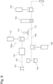
- Fig. 1 shows an example of a mechanical foaming device 100 that applies foam beads 110 to a surface by using a dispenser 1 according to the one embodiment of the present invention.
- the mechanical foaming device 100 includes a gas conduit 107 transporting gas supplied from a gas supply source 101 (e.g., factory-pressured air); a material conduit 108 transporting a paste material supplied from a paste material supply source 102 (e.g., a pail pump); a connection part 103 to which the gas conduit 107 and the material conduit 108 are connected; a mixer 104 that mixes together the gas and the paste material coming out of the connection part 103; and a constant flow amount cylinder 105 that causes a flow of the mixture formed by the mixer 104 to be in a constant flow amount.
- the mechanical foaming device 100 includes a robot 106 and the dispenser 1 having a nozzle part 2 and being attached to an arm of the robot 106.
- the dispenser 1 discharges, from the nozzle part 2, the mixture of the gas and the paste material supplied from the constant flow amount cylinder 105.
- the discharged mixture is foamed and applied to the surface.
- a foamed body applied from the nozzle part 2 forms the foam beads 110 on the surface.
- the paste material is liquid resin (which may be a hot melt material) that has fluidity and is obtained by adding a hardening agent, a hardening accelerator, a filler, a stabilizer, an additive and/or the like to reactive liquid resin such as an isocyanate, alkoxy silyl, acryl, epoxy, or the like.
- a hardening agent such as an isocyanate, alkoxy silyl, acryl, epoxy, or the like.
- the mixture of the paste material and the gas is in a state in which the gas is micro-dispersed in the paste material. After that, when the resin is hardened by thermosetting, moisture curing, UV curing, or the like, the foamed body is formed.
- the connection part 103 in one mode includes, for example, two piston pumps 111 and 112 and is structured by connecting the gas conduit 107 and the material conduit 108 to each of the cylinders of the piston pumps 111 and 112.
- the connection part 103 to cylinder spaces formed by raising the pistons of the piston pumps 111 and 112, the gas transported from the gas conduit 107 and the paste material transported from the material conduit 108 are sequentially supplied (in no particular order).
- the gas and the paste material in the cylinder spaces are pumped forward to the mixer 104.
- the two piston pumps 111 and 112 alternately, the mixture is inceimpulsly supplied to the mixer 104. It is therefore possible to continuously discharge the beads 110 from the dispenser 1.
- connection part 103 in the abovementioned mode of the present invention does not necessarily need to have two piston pumps. It is acceptable to use one piston pump or three or more piston pumps.
- the mixer 104 may be a dynamic mixer or a static mixer.
- Fig. 9 shows a connection part 103b according to another mode of the present invention.
- the connection part 103b is structured as a part in which the gas conduit 107 is connected to the material conduit 108 at a connection point 115 via a piston pump and an opening/closing valve 114.
- the gas conduit 107 is connected to the material conduit 108 at the connection point 115 via a piston pump 113 and the opening/closing valve 114.
- the gas transported from the gas conduit 107 is forwarded while the gas amount is controlled by a gas supply device 116.
- the gas in the cylinder space is compressed.
- opening the opening/closing valve 114 the compressed gas is mixed into the paste material being transported through the material conduit 108.
- the cylinder space formed at the time of raising the piston of the piston pump 113 has a prescribed capacity, it is possible to keep constant the amount of the gas to be mixed into the paste material at the time of lowering the piston, by adjusting the amount of the gas forwarded by the gas supply device 116 so that the pressure of the gas in the cylinder space is at a prescribed level.
- the flow amount of the paste material flowing through the material conduit 108 by using a constant flow amount pump 109, it is possible to control the proportion between the amount of the paste material and the amount of the gas to be constant and to thus achieve a desired foam expansion ratio.
- the proportion between the amount of the paste material and the amount of the gas is also possible to control the proportion between the amount of the paste material and the amount of the gas to be constant, by measuring the flow amount of the paste material flowing through the material conduit 108 and adjusting the gas amount in accordance with the flow amount of the paste material.
- the flow amount of the paste material forwarded by the constant flow amount pump 109 may fluctuate, as long as the ratio between a total amount of the paste material and a total amount of the gas to be mixed therewith in a certain period of time is substantially constant.
- control may be exercised to substantially achieve a certain target value.
- Fig. 10 shows a connection part 103c according to yet another mode of the present invention.
- an opening/closing valve is structured as a needle- or ball- type pulse valve 117 so as to control the introduction of the gas.
- Another mode is also acceptable in which the pressure before the pulse valve 117 and the material pressure in the connection point 115 are measured and set, so as to control the amount of the introduced gas.
- connection point of the present invention are not limited to the examples of 103b and 103c described above. Possible examples include a mode in which high-pressure gas is introduced by structuring the gas supply source 101 with a high-pressure tank or the like, for example, while the piston pump 113 and the gas supply device 116 are omitted. Further, the constant flow amount pump 109 may be provided on either the upstream side or the downstream side of the connection point 115.
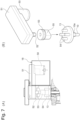
- the dispenser 1 includes a body 11 and the nozzle part 2 attached to a tip end part of the body 11.
- the nozzle part 2 has formed therein a hollow space 20 penetrating from the basal end to the tip end of the nozzle part 2.
- a basal end opening 21 is formed at the basal end of the nozzle part 2
- a tip end opening 22 is formed at the tip end of the nozzle part 2.
- a tapered section 23 is formed in which the inside diameter of the hollow space 20 on each cross-sectional plane perpendicular to the axial direction decreases toward the tip end opening 22.
- the needle part 3 is inserted in the hollow space 20 of the nozzle part 2. As explained later, as a result of the needle part 3 moving up and down on the inside of the hollow space 20, the nozzle part 2 is opened and closed.
- the nozzle part 2 is structured by connecting a nozzle body 24 and a nozzle tip end part 25 to each other by using respective engagement parts 27 and 28 thereof.
- the nozzle body 24 and the nozzle tip end part 25 have tapered sections having mutually the same inclination rate (the rate of change of the inside diameter with respect to the length in the axial direction), so that the tapered section 23 having the same inclination rate as a whole is formed by smoothly connecting the inner surfaces to each other.
- Possible structures of the nozzle part 2 include one in which the nozzle body 24 and the nozzle tip end part 25 are integrally formed. Alternatively, as explained in detail later, the inclination rate of the tapered section 23 may vary among different locations.
- the abovementioned basal end opening 21 is formed at the basal end of the nozzle body 24, the abovementioned basal end opening 21 is formed.
- an engagement part 26 for attaching the nozzle part 2 while being engaged with the body 11 of the dispenser 1 is formed at the farthest tip end of the nozzle tip end part 25, a discharge port 29 having the tip end opening 22 is formed at the farthest tip end of the nozzle tip end part 25, a discharge port 29 having the tip end opening 22 is formed.
- the inner surface of the discharge port 29 is formed to have an inside dimeter that is equal, in the whole length thereof, to the inside diameter of the tip end opening 22.
- the tapered section 23 ends at the most rearward edge of the inner surface of the discharge port 29.
- the needle part 3 for opening and closing the nozzle part 2 includes, as shown in Fig. 4 in detail, a needle body 30, a basal end part 31, a tip end part 32 formed in a tapered shape, and a large diameter part 33 formed in the vicinity of the basal end part 31.
- the basal end part 31 has an axial-direction groove 34 formed therein.
- the diameter of a tip end 35 (in the vicinity of the farthest tip end) of the tip end part 32 is formed to be equal to the inside diameter of the discharge port 29 or to be equal to the inside diameter of the tapered section 23 positioned in the vicinity of the discharge port 29. Accordingly, when the needle part 3 is inserted in the hollow space 20 of the nozzle part 2 and advanced, the tip end 35 of the needle part 3 is engaged in a closed position T1 ( Fig. 3 ) on the inner wall of the tapered section 23 (including the boundary between the tapered section 23 and the discharge port 29), and at that time, the nozzle part 2 is closed (the state shown in Figs. 2(A) and 2(B) ).
- the closed position T1 may be set either in the vicinity of the boundary between the tapered section 23 and the discharge port 29 or inside the tapered section 23 positioned behind the discharge port 29, in accordance with the diameter of the tip end 35 of the needle part 3 and the inside diameter of the tapered section 23.
- the inclination rate of the tapered section 23 is determined in such a manner that, as shown in Fig. 3 , the inside diameter d2 in a position T2 distant rearward from the closed position T1 by a distance 1 four times the diameter d1 of the tip end opening 22 is approximately 1.6 times larger than the diameter d1 of the tip end opening 22.
- the body 11 of the dispenser 1 includes: an introduction port 5 through which the mixture of the gas and the paste material is introduced; and a passage 6 extending from the introduction port 5 to the inside of the body 11.
- the passage 6 is linked to the basal end opening 21 of the nozzle part 2 and is connected from the introduction port 5 via the passage 6 through the hollow space 20 of the nozzle part 2 to the tip end opening 22, so that a flow path 4 for the mixture is formed in the dispenser 1, extending from the introduction port 5 to the tip end opening 22.
- the body 11 includes: a support part 19 that slidably supports the needle part 3 in a hermetic state; a cylinder part 7 formed behind (above in the drawing) the support part 19; the piston part 8 that moves up and down within the cylinder part 7; and a compressed air port 9 through which compressed air is put into and taken out of the space formed between the piston part 8 and the bottom face of the cylinder part 7.
- the piston part 8 With the piston part 8, the large diameter part 33 formed in the vicinity of the basal end of the needle part 3 is fitted, so that the basal end part 31 of the needle part 3 protrudes upward from the piston part 8.
- the piston part 8 is biased downward by a spring (not shown) toward the position shown in Fig.
- the needle part 3 is closing the flow path 4 of the nozzle part 2.
- the piston part 8 may be biased downward by compressed air pumped into the space in the cylinder part 7 positioned above the piston part 8.
- the mixture of the gas and the paste material When the mixture of the gas and the paste material is supplied through the introduction port 5, the mixture passes through the flow path 4 and reaches the vicinity of the tip end opening 22 of the nozzle part 2.
- the needle part 3 When the needle part 3 has retreated upward to open the tip end opening 22, the mixture is discharged from the tip end opening 22 and is applied to the surface as a foamed body.
- the needle part 3 When the needle part 3 is moved downward, because the tip end of the needle part 3 closes the tip end opening 22, the flow path 4 is closed so that the mixture stops being discharged.
- a stopper support part 16 that defines the top face of the cylinder part 7.
- the stopper support part 16 has formed therein a penetrating hole 16a extending in the axial direction.
- a screw thread is formed on the inner surface of the penetrating hole 16a.
- a rod 10 on which a screw thread 10a is formed is screwed into the penetrating hole 16a.
- a tip end part 14 of the rod 10 protrudes into the cylinder part 7.
- the stopper support part 16, the rod 10, and the tip end part 14 thereof function as a stopper that restricts the operation range of the needle part 3.
- the distance 1 is equal to or longer than four times the diameter d1 of the tip end opening 22.
- the screwing of the rod 10, i.e., the adjustment of the operation range of the needle part 3 may be performed manually; however, in the present embodiment, an electric stopper position adjusting part is employed as shown in Figs. 2(A) and 2(B) .
- the electric stopper position adjusting part includes an electric motor part 18 and is configured to transmit the rotation of the electric motor part 18 to a basal end part 13 of the rod 10 via a rotation transmitting part 12.
- the electric motor part 18 includes: an electric motor 50; a reduction gear 51 that reduces the rotation speed of the electric motor 50; an output shaft 52 of the reduction gear 51; and a rotation plate 53 fitted with the output shaft 52.
- the rotation transmitting part 12 ( Fig. 2(A) ) is structured as a result of fitting a plate part 55 that perpendicularly extends from a bottom part of the rotation plate 53 into the gaps between the adjacently-positioned cylindrical projections 54, so that the rotation of the output shaft 52 of the electric motor part 18 is transmitted to the rod 10.
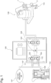
- the dispenser 1 further includes a controller 17 that controls the electric motor part 18 so as to adjust the position of the tip end part 14 of the rod 10, i.e., the operation range of the needle part 3 (3b).
- the controller 17 is arranged in a control panel of the mechanical foaming device 100 in Fig. 1 , the present invention is not limited to this example.
- the dispenser 1 includes a pressure sensor 15 provided in the flow path 4. A pressure detection signal from the pressure sensor 15 is sent to the controller 17, so that the controller 17 is able to use the pressure detection signal, i.e., the pressure in the flow path 4 for controlling the electric motor part 18.
- nozzle part 2 and the needle part 3 have thus been described as embodiments of the present invention; however, the present invention is not limited to these examples.
- the nozzle part 2 and the needle part 3 described above are regarded as a first modification example, a nozzle part and a needle part according to a second modification example will be explained, with reference to Figs. 5 and 6 .
- Figs. 5 and 6 some of the constituent elements that are the same as those in the first modification example will be referred to by appending the letter "b" to the same reference numerals. Detailed explanations of those elements will be omitted, and the following will primarily describe differences.
- a tapered section 23b is formed with a plurality of tapered subsections 61, 62, 63, 64, and 65 having mutually-different inclination rates, which is different from the nozzle part 2 according to the first modification example.
- a needle part 3b shown in Fig. 6 is inserted in a hollow space 20b of the nozzle part 2b.
- the needle part 3b includes a needle body 30b, a basal end part 31b, a tip end part 32b formed in a tapered shape, and a large diameter part 33b formed in the vicinity of the basal end part 31b.
- a difference from the first modification example lies in that there is a step between the needle body 30b and the tip end part 32b.
- the inclination rate of the tapered section 23b (the tapered subsection 65 in the example in Fig. 5 ) is determined in such a manner that the inside diameter d2' in a position T2' distant rearward from a closed position T 1' by a distance 1' four times the diameter d1' of the tip end opening 22b is approximately 2.9 times larger than the diameter d1' of the tip end opening 22b.
- the inclination rate of the tapered section is larger in the second modification example.
- a preferable range of the inclination rate d2/d1 is 1.1 to 4.
- a mixture in which gas and a paste material are micro-dispersed is supplied to the introduction port 5 of the dispenser 1 from the mechanical foaming device 100.
- the introduced mixture passes through the flow path 4 and reaches the vicinity of the tip end opening 22 (22b) of the nozzle part 2 (2b).
- the robot 106 introduces compressed air to the cylinder part 7 through the compressed air port 9. Due to the introduced compressed air, the piston part 8 rises so that the tip end 35 (35b) of the needle part 3 (3b) moves away from the closed position T1 (T1'), and the flow path 4 reaching the stopper tip end opening 22 (22b) changes from the closed state to the open state.
- the basal end part 31 (31b) of the needle part 3 (3b) abuts against the tip end part 14 of the rod 10 and stops.
- the foamed body passes through the open flow path 4 and is discharged from the tip end opening 22 (22b) to be applied to a surface as the foam beads 110.
- the mixture passing through the flow path 4 is reduced in pressure when the tip end opening 22 (22b) is opened, but there is no drastic change in the inside diameter or the pressure while the mixture passes through the tapered section 23 (23b).
- the mixture is able to maintain relatively high pressure until immediately before being discharged. Accordingly, it is possible to avoid the situation where the bubbles become large due to aggregation caused by the pressure getting lower during the passing through the nozzle. It is therefore possible to keep small the foamed cells of the foamed body after being discharged.
- the bubbles are prevented from becoming large, it is possible to inhibit the bubbles from breaking and to thus stabilize the foam expansion ratio.
- the desired foam expansion ratio is preferably 3 times or more and may be 3.5 times, 4 times, or 5 times.
- variance of the foam expansion ratio is 10% or lower and is preferably 5%.
- the present invention realizes the desired foam expansion ratio and is also able to keep the variance thereof within the preferable range.
- the tapered section 23 (23b) because it is possible to maintain the pressure of the mixture relatively high until immediately before being discharged, there is no need to supply the paste material to the dispenser 1 at extremely high pressure. It is therefore possible to proactively prevent clogging of the material and reactions of the mixture before being discharged.
- the pressure of the mixture at the time of being discharged has a certain relationship not only with the viscosity of the paste material and the discharge flow amount of the mixture, but also with a needle gap amount, which is a value indicating an operation range of the needle part 3 (3b).
- the needle gap amount is the distance 1 (1') between the stop position T2 (T2') and the closed position T1 (T1') of the tip end 35 (35b), when the needle part 3 (3b) abuts against the tip end part 14 of the rod 10.
- Fig. 8 shows a relationship of mixture discharge pressure with needle gap amounts.
- A1 denotes a resultant from the first modification example (the nozzle part 2 and the needle part 3) using a standard paste material (viscosity: 80,000 mPa ⁇ s (measured shear velocity: 4.2 sec -1 ));
- A2 denotes a result of the first modification example (the nozzle part 2 and the needle part 3) using a paste material having a high viscosity (viscosity: 120,000 mPa ⁇ s);
- B1 denotes a result of the second modification example (the nozzle part 2b and the needle part 3b) using the standard paste material.
- the paste material having the high viscosity was obtained by slightly increasing the viscosity by leaving the standard paste material at 40°C for approximately two weeks. Further, with A1 and B 1, tests were performed with discharge flow amounts of 50 g/min and 100 g/min.
- the graph in Fig. 8 indicates that, in all the dispensers, as the needle gap amount increases, the discharge pressure drastically decreases and approaches a certain level of pressure.
- the needle gap amount of the needle part 3 (3b) should be adjusted so as to achieve a desirable level of pressure that will exert the abovementioned advantage effect with the used dispenser, with respect to the discharge flow amount of the mixture.
- the controller 17 is configured to calculate the position T2 (T2') within the nozzle part 2 (2b) in which the tip end 35 (35b) of the needle part 3 (3b) forms the needle gap amount achieving the desired level of pressure, to further calculate the position of the tip end part 14 of the rod 10, i.e., the screw-in amount of the rod 10, corresponding to the position T2 (T2'), and to control the rotation of the electric motor 50 in the electric motor part 18 to rotate the rod 10 with the calculated screw-in amount.
- the controller 17 exercises feedback control on the needle gap amount by controlling the electric motor 50 so that the pressure of the mixture in the flow path 4 detected by the pressure sensor 15 falls within a desirable pressure range.
- the controller 17 may be omitted. In that situation, a display device displaying the pressure detected by the pressure sensor 15 is provided, so that the user is able to adjust the operation range of the needle part 3 (3b) while looking at the displayed pressure level.
- the dispenser 1 is controlled as being attached to the robot 106; however, another configuration is also acceptable in which the foamed body is discharged as the user holds the dispenser 1 and presses a switch. Further, it is also acceptable to use a mechanism for mixing the gas and the paste material together that is different from the mechanical foaming device 100.
- the example described above employs the raising mechanism of the piston part 8 using the compressed air introduced to the inside of the cylinder part 7 through the compressed air port 9 and the lowering mechanism of the spring (not shown); however, it is also acceptable to employ raising and lowering mechanisms for the needle part 3 or 3b using an electric motor.
Landscapes
- Engineering & Computer Science (AREA)
- Mechanical Engineering (AREA)
- Chemical & Material Sciences (AREA)
- Analytical Chemistry (AREA)
- Physics & Mathematics (AREA)
- Fluid Mechanics (AREA)
- Coating Apparatus (AREA)
- Accessories For Mixers (AREA)
- Application Of Or Painting With Fluid Materials (AREA)
Claims (6)
- Spender (1), der zur Abgabe einer Mischung aus Gas und einem pastösen Material verwendet wird, der Spender umfassend:ein Düsenteil (2), das in einem Spitzenendteil der Abgabevorrichtung bereitgestellt ist und eine Spitzenendöffnung (22) aufweist, durch die die Mischung abgegeben wird;einen Strömungsweg (4) für die Mischung, der sich von einem Einführteil (5) für die Mischung durch eine Innenseite des Düsenteils zu der Spitzenendöffnung (22) erstreckt;ein Nadelteil (3), das in dem Strömungsweg des Düsenteils beweglich ist, um den Strömungsweg zu öffnen und zu schließen; undein Antriebsteil (7, 8, 9), das den Nadelteil antreibt, wobeidas Düsenteil einen verjüngten Abschnitt (23) aufweist, in dem ein Innendurchmesser des Strömungsweges des Düsenteils in Richtung der Spitzenendöffnung abnimmt, wobei der Innendurchmesser relativ zu einem Arbeitsbereich eines Spitzenendes des Nadelteils ist,infolgedessen, dass das Spitzenende des Nadelteils an eine geschlossene Position des verjüngten Abschnitts anstößt, der Strömungsweg für die Mischung geschlossen ist, während infolgedessen, dass sich das Spitzenende des Nadelteils von der geschlossenen Position wegbewegt, der Strömungsweg geöffnet ist, undder Spender weiter ein Stopperteil (10, 14, 16) umfasst, das einen Bewegungsbereich des Spitzenendes des Nadelteils auf einen Bereich von der geschlossenen Position bis zu einer relativ zu der geschlossenen Position rückwärtig angeordneten Stoppposition begrenzt, und ein Stopperpositions-Einstellungsteil (10a, 16a, 13, 12, 18), das eine Position des Stopperteils einstellt, um die Stoppposition zu ändern, wobei das Stopperpositions-Einstellungsteil umfassteine Stange (10), die in einen Körper (11) des Spenders in einer axialen Richtung eingeschraubt ist, wobei eine Position der Stange in der axialen Richtung entsprechend einem Betrag des Einschraubens in den Körper eingestellt wird, und das Nadelteil infolgedessen, dass ein Spitzenendteil (14) der Stange, das gegen ein Basisendteil (31) des Nadelteils anstößt, gestoppt wird, undeinen Drucksensor (15), der den Druck der Mischung im Strömungsweg misst,dadurch gekennzeichnet, dass das Stopperpositions-Einstellungsteil weiter eines aus (i) und (ii) einschließt:(i) einen Elektromotor (50), der so angeordnet ist, dass er die Stange dreht, und
eine Steuereinheit (17), die die Stoppposition steuert, indem sie einen Drehbetrag der von dem Elektromotor gedrehten Stange so steuert, dass der von dem Drucksensor gemessene Druck in einen gewünschten Druckbereich fällt, in Bezug auf eine Ausstoßmenge der Mischung,(ii) einen Mechanismus, der die Stange manuell drehbar macht, undeine Anzeigeeinheit, die den vom Drucksensor gemessenen Druck anzeigt,wobei der Betriebsbereich des Nadelteils (3) manuell eingestellt werden kann, indem ein Drehbetrag der durch den Mechanismus gedrehten Stange eingestellt wird, während der durch den Drucksensor erfasste und durch die Anzeigeeinheit angezeigte Druckpegel beobachtet wird, undwobei der Spender so ausgebildet ist, dass der Druck der Mischung, die aus der Spitzenendöffnung abgegeben wird, durch Einstellen des Arbeitsbereichs des Nadelteils (3) in Bezug auf die abgegebene Durchflussmenge der Mischung gesteuert wird. - Spender nach Anspruch 1, wobei
eine hinterste Position der Stoppposition, die durch das Stopperpositions-Einstellungsteil eingestellt wird, eine Position ist, die von der geschlossenen Position um einen Abstand entfernt ist, der gleich oder länger als das Vierfache eines Durchmessers der Spitzenendöffnung ist. - Spender nach Anspruch 1 oder 2, wobei
in der Position, die von der geschlossenen Position um einen Abstand nach hinten entfernt ist, der das Vierfache des Durchmessers der Spitzenendöffnung beträgt, der Innendurchmesser des Strömungswegs 1,1 bis 3 mal größer ist als der Durchmesser der Spitzenendöffnung. - Mechanische Schäumvorrichtung (100), die eine Mischung aus Gas und einem pastösen Material ausstößt, wobei die mechanische Schäumvorrichtung umfasst:eine Gasleitung (107), die zum Transport des Gases verwendet wird;eine Materialleitung (108), die zum Transport des pastösen Materials verwendet wird;ein Verbindungsteil, mit dem die Gasleitung und die Materialleitung verbunden sind;
ein Mischteil, das das Gas und das pastöse Material, die aus dem Verbindungsteil herauskommen, miteinander mischt; undeine Vorrichtung (105) für eine konstante Durchflussmenge, die dem Spender die Mischung aus dem Gas und dem pastösen Material, das durch den Mischteil gemischt wurde, in einer konstanten Durchflussmenge zuführt; undden Spender (1) nach einem der Ansprüche 1 bis 3, der eine Zufuhr der Mischung aus dem Gas und dem pastösen Material aus dem Mischteil erhält. - Mechanische Schäumvorrichtung nach Anspruch 4, wobeidas Verbindungsteil mindestens eine Kolbenpumpe (103) ist,die Gasleitung und die Materialleitung mit einem Zylinder der Kolbenpumpe verbunden sind, undin einen Zylinderraum, der durch Anheben eines Kolbens der Kolbenpumpe gebildet wird, das durch die Gasleitung transportierte Gas und das durch die Materialleitung transportierte pastöse Material zugeführt werden, so dass das Gas und das pastöse Material im Zylinderraum durch Absenken des Kolbens nach vorne zum Mischteil gepumpt werden.
- Mechanische Schäumvorrichtung nach Anspruch 4, wobeidas Verbindungsteil ein Teil ist, in dem die Gasleitung mit der Materialleitung über eine Kolbenpumpe und ein Öffnungs-/Schließventil verbunden ist, undin einen Zylinderraum, der durch Anheben eines Kolbens der Kolbenpumpe bei geschlossenem Öffnungs-/Schließventil gebildet wird, das durch die Gasleitung transportierte Gas zugeführt wird, so dass das Gas im Zylinderraum durch Absenken des Kolbens komprimiert wird, und so dass das komprimierte Gas in das durch die Materialleitung transportierte pastöse Material durch Öffnen des Öffnungs-/Schließventils gemischt wird.
Applications Claiming Priority (1)
| Application Number | Priority Date | Filing Date | Title |
|---|---|---|---|
| PCT/JP2019/051559 WO2021131055A1 (ja) | 2019-12-27 | 2019-12-27 | ガスとペースト材料との混合物を吐出するためのディスペンサー及びノズル、並びに、機械発泡装置 |
Publications (3)
| Publication Number | Publication Date |
|---|---|
| EP3868480A4 EP3868480A4 (de) | 2021-08-25 |
| EP3868480A1 EP3868480A1 (de) | 2021-08-25 |
| EP3868480B1 true EP3868480B1 (de) | 2024-04-03 |
Family
ID=76574196
Family Applications (1)
| Application Number | Title | Priority Date | Filing Date |
|---|---|---|---|
| EP19861262.4A Active EP3868480B1 (de) | 2019-12-27 | 2019-12-27 | Spender und düse zum ausbringen einer mischung aus gas und pastenmaterial und mechanische schäumvorrichtung |
Country Status (5)
| Country | Link |
|---|---|
| US (1) | US12496599B2 (de) |
| EP (1) | EP3868480B1 (de) |
| JP (1) | JP7278419B2 (de) |
| CN (1) | CN114901402B (de) |
| WO (1) | WO2021131055A1 (de) |
Families Citing this family (5)
| Publication number | Priority date | Publication date | Assignee | Title |
|---|---|---|---|---|
| FR3113848B1 (fr) * | 2020-09-07 | 2023-06-16 | Exel Ind | Dispositif d’application d’un produit, machine comprenant un tel dispositif et procédé de contrôle d’une telle machine |
| EP4108413B1 (de) * | 2021-06-25 | 2023-07-26 | Sunstar Engineering Inc. | Verfahren zum einstellen des drucks des gemischs von gas und pastematerial, das aus dem spender ausgetragen wird |
| JPWO2023135797A1 (de) * | 2022-01-17 | 2023-07-20 | ||
| CN116587514B (zh) * | 2023-05-15 | 2025-10-24 | 中科美菱低温科技股份有限公司 | 一种防堵塞的发泡枪头及超低温冷柜 |
| CN120206719B (zh) * | 2025-05-12 | 2026-04-17 | 安吉新泰海绵制品有限公司 | 一种高匀度发泡设备及其在海绵生产中的应用 |
Citations (2)
| Publication number | Priority date | Publication date | Assignee | Title |
|---|---|---|---|---|
| US7422164B2 (en) * | 2002-01-18 | 2008-09-09 | Anest Iwata Corporation | Spray gun with pressure display |
| US8857732B2 (en) * | 2009-05-07 | 2014-10-14 | Sata Gmbh & Co Kg | Spray gun with pressure measuring device |
Family Cites Families (27)
| Publication number | Priority date | Publication date | Assignee | Title |
|---|---|---|---|---|
| NL256540A (de) | 1960-05-27 | 1900-01-01 | ||
| CA1155094A (en) | 1980-05-09 | 1983-10-11 | Jacob J. Boone | Liquid dispensing device |
| US4465212A (en) * | 1980-05-09 | 1984-08-14 | Nordson Corporation | Liquid dispensing device |
| DE3542767A1 (de) | 1985-12-04 | 1987-06-11 | Karl Lenhardt | Vorrichtung zum foerdern von zwei zaehfluessigen substanzen in vorgegebenem mengenverhaeltnis aus zwei vorratsbehaeltern zu einer oder mehreren duesen |
| EP0412978B1 (de) | 1988-04-20 | 1992-11-11 | Lenhardt Maschinenbau GmbH | Vorrichtung zum abgeben hochviskoser, pastöser, kompressibler substanzen |
| US5089190A (en) | 1989-11-13 | 1992-02-18 | Nordson Corporation | Method and apparatus for hollow core extrusion of high viscosity materials |
| US5207352A (en) | 1991-04-19 | 1993-05-04 | Nordson Corporation | Method and apparatus for dispensing high viscosity fluid materials |
| DE4217835C2 (de) | 1992-05-29 | 2001-12-13 | Drei Bond Gmbh Chemische Verbi | Regelventil |
| WO2000029194A1 (fr) | 1998-11-12 | 2000-05-25 | Sunstar Giken Kabushiki Kaisha | Procede et dispositif de formation de perles |
| DE19914343A1 (de) * | 1999-03-30 | 2000-10-05 | Miroslaw Muche | Vorrichtung zum Auftragen von flüssigem und pastösem Material |
| DE602004028571D1 (de) * | 2003-01-07 | 2010-09-23 | Sunstar Engineering Inc | Verfahren zur herstellung eines gehärteten produktes |
| JP2004330600A (ja) | 2003-05-07 | 2004-11-25 | Japan Steel Works Ltd:The | 発泡成形体の成形方法 |
| JP4409889B2 (ja) | 2003-09-08 | 2010-02-03 | 住友ゴム工業株式会社 | 樹脂発泡体の製造方法および該発泡体を用いた紙葉類重送防止部材 |
| JP4725169B2 (ja) | 2005-04-12 | 2011-07-13 | 横浜ゴム株式会社 | 高粘度材料の気泡混入方法及びその装置 |
| US7717059B2 (en) | 2005-06-15 | 2010-05-18 | Spraying Systems Co. | Liquid adhesive dispensing system |
| US7703705B2 (en) | 2007-02-16 | 2010-04-27 | Nordson Corporation | Apparatus and method for dispensing a mixture of a gas and a fluid material |
| JP5293989B2 (ja) * | 2007-07-24 | 2013-09-18 | ノードソン株式会社 | 少量液体の噴霧装置 |
| JP5060236B2 (ja) | 2007-10-01 | 2012-10-31 | 倉敷紡績株式会社 | ポリウレタンフォーム製造装置及びその製造方法 |
| US7900800B2 (en) * | 2007-10-19 | 2011-03-08 | Nordson Corporation | Dispensing apparatus with heat exchanger and method of using same |
| KR101126722B1 (ko) * | 2009-03-30 | 2012-03-29 | 반석정밀공업주식회사 | 액체 토출장치 |
| US8136705B2 (en) * | 2009-04-09 | 2012-03-20 | Illinois Tool Works Inc. | Magnetic drive for dispensing apparatus |
| US8333307B2 (en) * | 2009-10-06 | 2012-12-18 | Nordson Corporation | Liquid dispensing module |
| JP2013146692A (ja) * | 2012-01-20 | 2013-08-01 | Three Bond Co Ltd | 材料吐出装置 |
| JP2016109776A (ja) | 2014-12-03 | 2016-06-20 | 三菱電機株式会社 | シールディスペンサ装置および液晶表示装置の製造方法 |
| EP3473334B1 (de) | 2015-02-05 | 2022-01-05 | Sunstar Engineering Inc. | Verfahren zum mischen von gas in hochviskoses material und vorrichtung dafür |
| JP6837276B2 (ja) | 2015-07-30 | 2021-03-03 | 旭有機材株式会社 | 制御装置を備えた現場吹付け型発泡機 |
| JP6623741B2 (ja) | 2015-12-18 | 2019-12-25 | 株式会社スリーボンド | 機械式発泡装置および機械式発泡方法 |
-
2019
- 2019-12-27 US US17/789,366 patent/US12496599B2/en active Active
- 2019-12-27 CN CN201980103348.4A patent/CN114901402B/zh active Active
- 2019-12-27 EP EP19861262.4A patent/EP3868480B1/de active Active
- 2019-12-27 WO PCT/JP2019/051559 patent/WO2021131055A1/ja not_active Ceased
- 2019-12-27 JP JP2021566754A patent/JP7278419B2/ja active Active
Patent Citations (2)
| Publication number | Priority date | Publication date | Assignee | Title |
|---|---|---|---|---|
| US7422164B2 (en) * | 2002-01-18 | 2008-09-09 | Anest Iwata Corporation | Spray gun with pressure display |
| US8857732B2 (en) * | 2009-05-07 | 2014-10-14 | Sata Gmbh & Co Kg | Spray gun with pressure measuring device |
Also Published As
| Publication number | Publication date |
|---|---|
| EP3868480A4 (de) | 2021-08-25 |
| JPWO2021131055A1 (de) | 2021-07-01 |
| CN114901402A (zh) | 2022-08-12 |
| JP7278419B2 (ja) | 2023-05-19 |
| EP3868480A1 (de) | 2021-08-25 |
| US12496599B2 (en) | 2025-12-16 |
| WO2021131055A1 (ja) | 2021-07-01 |
| CN114901402B (zh) | 2024-08-06 |
| US20230110347A1 (en) | 2023-04-13 |
Similar Documents
| Publication | Publication Date | Title |
|---|---|---|
| US12496599B2 (en) | Dispenser and nozzle for discharging mixture of gas and paste material and mechanical foaming device | |
| US6691895B2 (en) | Mixing rotary positive displacement pump for micro dispensing | |
| US5207352A (en) | Method and apparatus for dispensing high viscosity fluid materials | |
| US11154829B2 (en) | Method and metering device for metering a liquid or pasty product in a pressure-regulated manner | |
| US10618198B2 (en) | Device and method for foaming a viscous material | |
| US10407234B2 (en) | Two component fluid metering and mixing system | |
| US6935534B2 (en) | Mixing rotary positive displacement pump for micro dispensing | |
| EP3075442B1 (de) | Verfahren und vorrichtung zum mischen eines gases mit einem hochviskosen material | |
| US12521747B2 (en) | Method for adjusting pressure of mixture of gas and paste material discharged from dispenser | |
| US7597931B2 (en) | Device and method for producing a foam material | |
| EP3450024A1 (de) | Dosier- und applikationsanlage für ein feuchtigkeitshärtendes polymermaterial | |
| JP4636729B2 (ja) | 液体材料の吐出方法およびその装置 | |
| JP2017109192A (ja) | 機械式発泡装置および機械式発泡方法 | |
| JPH09206638A (ja) | 高粘度材料の発泡方法及び装置 | |
| JP3851895B2 (ja) | 高粘度材料の発泡方法及び装置 | |
| US20070235546A1 (en) | Viscoelastic liquid flow splitter and methods | |
| KR20200124169A (ko) | 액상 물질 토출 장치 | |
| JP7648920B2 (ja) | 発泡装置及び発泡方法 | |
| JP2023004902A5 (de) | ||
| JP3143195U (ja) | 圧力調節機構付の混合装置 | |
| JPH10337459A (ja) | 流動体の混合方法及び装置 | |
| WO2026058748A1 (ja) | 発泡装置の吐出部の構造及び発泡装置 |
Legal Events
| Date | Code | Title | Description |
|---|---|---|---|
| STAA | Information on the status of an ep patent application or granted ep patent |
Free format text: STATUS: UNKNOWN |
|
| STAA | Information on the status of an ep patent application or granted ep patent |
Free format text: STATUS: THE INTERNATIONAL PUBLICATION HAS BEEN MADE |
|
| PUAI | Public reference made under article 153(3) epc to a published international application that has entered the european phase |
Free format text: ORIGINAL CODE: 0009012 |
|
| STAA | Information on the status of an ep patent application or granted ep patent |
Free format text: STATUS: REQUEST FOR EXAMINATION WAS MADE |
|
| STAA | Information on the status of an ep patent application or granted ep patent |
Free format text: STATUS: EXAMINATION IS IN PROGRESS |
|
| 17P | Request for examination filed |
Effective date: 20200325 |
|
| A4 | Supplementary search report drawn up and despatched |
Effective date: 20201103 |
|
| AK | Designated contracting states |
Kind code of ref document: A1 Designated state(s): AL AT BE BG CH CY CZ DE DK EE ES FI FR GB GR HR HU IE IS IT LI LT LU LV MC MK MT NL NO PL PT RO RS SE SI SK SM TR |
|
| 17Q | First examination report despatched |
Effective date: 20210806 |
|
| DAV | Request for validation of the european patent (deleted) | ||
| DAX | Request for extension of the european patent (deleted) | ||
| GRAP | Despatch of communication of intention to grant a patent |
Free format text: ORIGINAL CODE: EPIDOSNIGR1 |
|
| STAA | Information on the status of an ep patent application or granted ep patent |
Free format text: STATUS: GRANT OF PATENT IS INTENDED |
|
| RIC1 | Information provided on ipc code assigned before grant |
Ipc: B29B 7/72 20060101ALI20231116BHEP Ipc: B05C 11/10 20060101ALI20231116BHEP Ipc: B29B 7/74 20060101ALI20231116BHEP Ipc: B29C 44/02 20060101ALI20231116BHEP Ipc: B29C 44/34 20060101ALI20231116BHEP Ipc: B29C 44/50 20060101ALI20231116BHEP Ipc: B29C 44/46 20060101ALI20231116BHEP Ipc: B05C 5/02 20060101AFI20231116BHEP |
|
| INTG | Intention to grant announced |
Effective date: 20231129 |
|
| GRAS | Grant fee paid |
Free format text: ORIGINAL CODE: EPIDOSNIGR3 |
|
| GRAA | (expected) grant |
Free format text: ORIGINAL CODE: 0009210 |
|
| STAA | Information on the status of an ep patent application or granted ep patent |
Free format text: STATUS: THE PATENT HAS BEEN GRANTED |
|
| P01 | Opt-out of the competence of the unified patent court (upc) registered |
Effective date: 20240202 |
|
| AK | Designated contracting states |
Kind code of ref document: B1 Designated state(s): AL AT BE BG CH CY CZ DE DK EE ES FI FR GB GR HR HU IE IS IT LI LT LU LV MC MK MT NL NO PL PT RO RS SE SI SK SM TR |
|
| REG | Reference to a national code |
Ref country code: CH Ref legal event code: EP |
|
| REG | Reference to a national code |
Ref country code: DE Ref legal event code: R096 Ref document number: 602019049720 Country of ref document: DE |
|
| REG | Reference to a national code |
Ref country code: IE Ref legal event code: FG4D |
|
| REG | Reference to a national code |
Ref country code: LT Ref legal event code: MG9D |
|
| REG | Reference to a national code |
Ref country code: NL Ref legal event code: MP Effective date: 20240403 |
|
| PG25 | Lapsed in a contracting state [announced via postgrant information from national office to epo] |
Ref country code: NL Free format text: LAPSE BECAUSE OF FAILURE TO SUBMIT A TRANSLATION OF THE DESCRIPTION OR TO PAY THE FEE WITHIN THE PRESCRIBED TIME-LIMIT Effective date: 20240403 |
|
| PG25 | Lapsed in a contracting state [announced via postgrant information from national office to epo] |
Ref country code: NL Free format text: LAPSE BECAUSE OF FAILURE TO SUBMIT A TRANSLATION OF THE DESCRIPTION OR TO PAY THE FEE WITHIN THE PRESCRIBED TIME-LIMIT Effective date: 20240403 |
|
| PG25 | Lapsed in a contracting state [announced via postgrant information from national office to epo] |
Ref country code: IS Free format text: LAPSE BECAUSE OF FAILURE TO SUBMIT A TRANSLATION OF THE DESCRIPTION OR TO PAY THE FEE WITHIN THE PRESCRIBED TIME-LIMIT Effective date: 20240803 |
|
| PG25 | Lapsed in a contracting state [announced via postgrant information from national office to epo] |
Ref country code: BG Free format text: LAPSE BECAUSE OF FAILURE TO SUBMIT A TRANSLATION OF THE DESCRIPTION OR TO PAY THE FEE WITHIN THE PRESCRIBED TIME-LIMIT Effective date: 20240403 |
|
| PG25 | Lapsed in a contracting state [announced via postgrant information from national office to epo] |
Ref country code: HR Free format text: LAPSE BECAUSE OF FAILURE TO SUBMIT A TRANSLATION OF THE DESCRIPTION OR TO PAY THE FEE WITHIN THE PRESCRIBED TIME-LIMIT Effective date: 20240403 Ref country code: FI Free format text: LAPSE BECAUSE OF FAILURE TO SUBMIT A TRANSLATION OF THE DESCRIPTION OR TO PAY THE FEE WITHIN THE PRESCRIBED TIME-LIMIT Effective date: 20240403 |
|
| PG25 | Lapsed in a contracting state [announced via postgrant information from national office to epo] |
Ref country code: GR Free format text: LAPSE BECAUSE OF FAILURE TO SUBMIT A TRANSLATION OF THE DESCRIPTION OR TO PAY THE FEE WITHIN THE PRESCRIBED TIME-LIMIT Effective date: 20240704 |
|
| PG25 | Lapsed in a contracting state [announced via postgrant information from national office to epo] |
Ref country code: PT Free format text: LAPSE BECAUSE OF FAILURE TO SUBMIT A TRANSLATION OF THE DESCRIPTION OR TO PAY THE FEE WITHIN THE PRESCRIBED TIME-LIMIT Effective date: 20240805 |
|
| PG25 | Lapsed in a contracting state [announced via postgrant information from national office to epo] |
Ref country code: ES Free format text: LAPSE BECAUSE OF FAILURE TO SUBMIT A TRANSLATION OF THE DESCRIPTION OR TO PAY THE FEE WITHIN THE PRESCRIBED TIME-LIMIT Effective date: 20240403 |
|
| PG25 | Lapsed in a contracting state [announced via postgrant information from national office to epo] |
Ref country code: CZ Free format text: LAPSE BECAUSE OF FAILURE TO SUBMIT A TRANSLATION OF THE DESCRIPTION OR TO PAY THE FEE WITHIN THE PRESCRIBED TIME-LIMIT Effective date: 20240403 |
|
| PG25 | Lapsed in a contracting state [announced via postgrant information from national office to epo] |
Ref country code: PL Free format text: LAPSE BECAUSE OF FAILURE TO SUBMIT A TRANSLATION OF THE DESCRIPTION OR TO PAY THE FEE WITHIN THE PRESCRIBED TIME-LIMIT Effective date: 20240403 |
|
| PG25 | Lapsed in a contracting state [announced via postgrant information from national office to epo] |
Ref country code: LV Free format text: LAPSE BECAUSE OF FAILURE TO SUBMIT A TRANSLATION OF THE DESCRIPTION OR TO PAY THE FEE WITHIN THE PRESCRIBED TIME-LIMIT Effective date: 20240403 |
|
| PG25 | Lapsed in a contracting state [announced via postgrant information from national office to epo] |
Ref country code: PT Free format text: LAPSE BECAUSE OF FAILURE TO SUBMIT A TRANSLATION OF THE DESCRIPTION OR TO PAY THE FEE WITHIN THE PRESCRIBED TIME-LIMIT Effective date: 20240805 Ref country code: PL Free format text: LAPSE BECAUSE OF FAILURE TO SUBMIT A TRANSLATION OF THE DESCRIPTION OR TO PAY THE FEE WITHIN THE PRESCRIBED TIME-LIMIT Effective date: 20240403 Ref country code: NO Free format text: LAPSE BECAUSE OF FAILURE TO SUBMIT A TRANSLATION OF THE DESCRIPTION OR TO PAY THE FEE WITHIN THE PRESCRIBED TIME-LIMIT Effective date: 20240703 Ref country code: LV Free format text: LAPSE BECAUSE OF FAILURE TO SUBMIT A TRANSLATION OF THE DESCRIPTION OR TO PAY THE FEE WITHIN THE PRESCRIBED TIME-LIMIT Effective date: 20240403 Ref country code: IS Free format text: LAPSE BECAUSE OF FAILURE TO SUBMIT A TRANSLATION OF THE DESCRIPTION OR TO PAY THE FEE WITHIN THE PRESCRIBED TIME-LIMIT Effective date: 20240803 Ref country code: HR Free format text: LAPSE BECAUSE OF FAILURE TO SUBMIT A TRANSLATION OF THE DESCRIPTION OR TO PAY THE FEE WITHIN THE PRESCRIBED TIME-LIMIT Effective date: 20240403 Ref country code: GR Free format text: LAPSE BECAUSE OF FAILURE TO SUBMIT A TRANSLATION OF THE DESCRIPTION OR TO PAY THE FEE WITHIN THE PRESCRIBED TIME-LIMIT Effective date: 20240704 Ref country code: FI Free format text: LAPSE BECAUSE OF FAILURE TO SUBMIT A TRANSLATION OF THE DESCRIPTION OR TO PAY THE FEE WITHIN THE PRESCRIBED TIME-LIMIT Effective date: 20240403 Ref country code: ES Free format text: LAPSE BECAUSE OF FAILURE TO SUBMIT A TRANSLATION OF THE DESCRIPTION OR TO PAY THE FEE WITHIN THE PRESCRIBED TIME-LIMIT Effective date: 20240403 Ref country code: CZ Free format text: LAPSE BECAUSE OF FAILURE TO SUBMIT A TRANSLATION OF THE DESCRIPTION OR TO PAY THE FEE WITHIN THE PRESCRIBED TIME-LIMIT Effective date: 20240403 Ref country code: BG Free format text: LAPSE BECAUSE OF FAILURE TO SUBMIT A TRANSLATION OF THE DESCRIPTION OR TO PAY THE FEE WITHIN THE PRESCRIBED TIME-LIMIT Effective date: 20240403 Ref country code: RS Free format text: LAPSE BECAUSE OF FAILURE TO SUBMIT A TRANSLATION OF THE DESCRIPTION OR TO PAY THE FEE WITHIN THE PRESCRIBED TIME-LIMIT Effective date: 20240703 |
|
| REG | Reference to a national code |
Ref country code: DE Ref legal event code: R097 Ref document number: 602019049720 Country of ref document: DE |
|
| PG25 | Lapsed in a contracting state [announced via postgrant information from national office to epo] |
Ref country code: DK Free format text: LAPSE BECAUSE OF FAILURE TO SUBMIT A TRANSLATION OF THE DESCRIPTION OR TO PAY THE FEE WITHIN THE PRESCRIBED TIME-LIMIT Effective date: 20240403 |
|
| PG25 | Lapsed in a contracting state [announced via postgrant information from national office to epo] |
Ref country code: EE Free format text: LAPSE BECAUSE OF FAILURE TO SUBMIT A TRANSLATION OF THE DESCRIPTION OR TO PAY THE FEE WITHIN THE PRESCRIBED TIME-LIMIT Effective date: 20240403 |
|
| PG25 | Lapsed in a contracting state [announced via postgrant information from national office to epo] |
Ref country code: RO Free format text: LAPSE BECAUSE OF FAILURE TO SUBMIT A TRANSLATION OF THE DESCRIPTION OR TO PAY THE FEE WITHIN THE PRESCRIBED TIME-LIMIT Effective date: 20240403 Ref country code: SK Free format text: LAPSE BECAUSE OF FAILURE TO SUBMIT A TRANSLATION OF THE DESCRIPTION OR TO PAY THE FEE WITHIN THE PRESCRIBED TIME-LIMIT Effective date: 20240403 |
|
| PG25 | Lapsed in a contracting state [announced via postgrant information from national office to epo] |
Ref country code: SM Free format text: LAPSE BECAUSE OF FAILURE TO SUBMIT A TRANSLATION OF THE DESCRIPTION OR TO PAY THE FEE WITHIN THE PRESCRIBED TIME-LIMIT Effective date: 20240403 |
|
| PG25 | Lapsed in a contracting state [announced via postgrant information from national office to epo] |
Ref country code: SM Free format text: LAPSE BECAUSE OF FAILURE TO SUBMIT A TRANSLATION OF THE DESCRIPTION OR TO PAY THE FEE WITHIN THE PRESCRIBED TIME-LIMIT Effective date: 20240403 Ref country code: SK Free format text: LAPSE BECAUSE OF FAILURE TO SUBMIT A TRANSLATION OF THE DESCRIPTION OR TO PAY THE FEE WITHIN THE PRESCRIBED TIME-LIMIT Effective date: 20240403 Ref country code: RO Free format text: LAPSE BECAUSE OF FAILURE TO SUBMIT A TRANSLATION OF THE DESCRIPTION OR TO PAY THE FEE WITHIN THE PRESCRIBED TIME-LIMIT Effective date: 20240403 Ref country code: EE Free format text: LAPSE BECAUSE OF FAILURE TO SUBMIT A TRANSLATION OF THE DESCRIPTION OR TO PAY THE FEE WITHIN THE PRESCRIBED TIME-LIMIT Effective date: 20240403 Ref country code: DK Free format text: LAPSE BECAUSE OF FAILURE TO SUBMIT A TRANSLATION OF THE DESCRIPTION OR TO PAY THE FEE WITHIN THE PRESCRIBED TIME-LIMIT Effective date: 20240403 |
|
| PLBE | No opposition filed within time limit |
Free format text: ORIGINAL CODE: 0009261 |
|
| STAA | Information on the status of an ep patent application or granted ep patent |
Free format text: STATUS: NO OPPOSITION FILED WITHIN TIME LIMIT |
|
| 26N | No opposition filed |
Effective date: 20250106 |
|
| PG25 | Lapsed in a contracting state [announced via postgrant information from national office to epo] |
Ref country code: SI Free format text: LAPSE BECAUSE OF FAILURE TO SUBMIT A TRANSLATION OF THE DESCRIPTION OR TO PAY THE FEE WITHIN THE PRESCRIBED TIME-LIMIT Effective date: 20240403 |
|
| PG25 | Lapsed in a contracting state [announced via postgrant information from national office to epo] |
Ref country code: MC Free format text: LAPSE BECAUSE OF FAILURE TO SUBMIT A TRANSLATION OF THE DESCRIPTION OR TO PAY THE FEE WITHIN THE PRESCRIBED TIME-LIMIT Effective date: 20240403 |
|
| REG | Reference to a national code |
Ref country code: CH Ref legal event code: PL |
|
| PG25 | Lapsed in a contracting state [announced via postgrant information from national office to epo] |
Ref country code: LU Free format text: LAPSE BECAUSE OF NON-PAYMENT OF DUE FEES Effective date: 20241227 |
|
| GBPC | Gb: european patent ceased through non-payment of renewal fee |
Effective date: 20241227 |
|
| PG25 | Lapsed in a contracting state [announced via postgrant information from national office to epo] |
Ref country code: SE Free format text: LAPSE BECAUSE OF FAILURE TO SUBMIT A TRANSLATION OF THE DESCRIPTION OR TO PAY THE FEE WITHIN THE PRESCRIBED TIME-LIMIT Effective date: 20240403 |
|
| REG | Reference to a national code |
Ref country code: BE Ref legal event code: MM Effective date: 20241231 |
|
| PG25 | Lapsed in a contracting state [announced via postgrant information from national office to epo] |
Ref country code: BE Free format text: LAPSE BECAUSE OF NON-PAYMENT OF DUE FEES Effective date: 20241231 Ref country code: GB Free format text: LAPSE BECAUSE OF NON-PAYMENT OF DUE FEES Effective date: 20241227 |
|
| PG25 | Lapsed in a contracting state [announced via postgrant information from national office to epo] |
Ref country code: FR Free format text: LAPSE BECAUSE OF NON-PAYMENT OF DUE FEES Effective date: 20241231 |
|
| PG25 | Lapsed in a contracting state [announced via postgrant information from national office to epo] |
Ref country code: CH Free format text: LAPSE BECAUSE OF NON-PAYMENT OF DUE FEES Effective date: 20241231 |
|
| PG25 | Lapsed in a contracting state [announced via postgrant information from national office to epo] |
Ref country code: IE Free format text: LAPSE BECAUSE OF NON-PAYMENT OF DUE FEES Effective date: 20241227 |
|
| PGFP | Annual fee paid to national office [announced via postgrant information from national office to epo] |
Ref country code: AT Payment date: 20251215 Year of fee payment: 7 |
|
| PG25 | Lapsed in a contracting state [announced via postgrant information from national office to epo] |
Ref country code: IT Free format text: LAPSE BECAUSE OF NON-PAYMENT OF DUE FEES Effective date: 20241227 |
|
| REG | Reference to a national code |
Ref country code: AT Ref legal event code: UEP Ref document number: 1671685 Country of ref document: AT Kind code of ref document: T Effective date: 20240403 |
|
| PGFP | Annual fee paid to national office [announced via postgrant information from national office to epo] |
Ref country code: DE Payment date: 20251222 Year of fee payment: 7 |
|
| PG25 | Lapsed in a contracting state [announced via postgrant information from national office to epo] |
Ref country code: IT Free format text: LAPSE BECAUSE OF NON-PAYMENT OF DUE FEES Effective date: 20241227 |
|
| PGFP | Annual fee paid to national office [announced via postgrant information from national office to epo] |
Ref country code: IT Payment date: 20251231 Year of fee payment: 7 |
|
| PGRI | Patent reinstated in contracting state [announced from national office to epo] |
Ref country code: IT Effective date: 20250430 |
|
| PG25 | Lapsed in a contracting state [announced via postgrant information from national office to epo] |
Ref country code: CY Free format text: LAPSE BECAUSE OF FAILURE TO SUBMIT A TRANSLATION OF THE DESCRIPTION OR TO PAY THE FEE WITHIN THE PRESCRIBED TIME-LIMIT Effective date: 20240403 |
|
| PG25 | Lapsed in a contracting state [announced via postgrant information from national office to epo] |
Ref country code: TR Free format text: LAPSE BECAUSE OF FAILURE TO SUBMIT A TRANSLATION OF THE DESCRIPTION OR TO PAY THE FEE WITHIN THE PRESCRIBED TIME-LIMIT Effective date: 20240403 |
|
| PG25 | Lapsed in a contracting state [announced via postgrant information from national office to epo] |
Ref country code: HU Free format text: LAPSE BECAUSE OF FAILURE TO SUBMIT A TRANSLATION OF THE DESCRIPTION OR TO PAY THE FEE WITHIN THE PRESCRIBED TIME-LIMIT; INVALID AB INITIO Effective date: 20191227 |
|
| PG25 | Lapsed in a contracting state [announced via postgrant information from national office to epo] |
Ref country code: LT Free format text: LAPSE BECAUSE OF FAILURE TO SUBMIT A TRANSLATION OF THE DESCRIPTION OR TO PAY THE FEE WITHIN THE PRESCRIBED TIME-LIMIT Effective date: 20240403 |