EP3868574A1 - Pneu à carcasse diagonale pour véhicule à deux roues - Google Patents
Pneu à carcasse diagonale pour véhicule à deux roues Download PDFInfo
- Publication number
- EP3868574A1 EP3868574A1 EP21150269.5A EP21150269A EP3868574A1 EP 3868574 A1 EP3868574 A1 EP 3868574A1 EP 21150269 A EP21150269 A EP 21150269A EP 3868574 A1 EP3868574 A1 EP 3868574A1
- Authority
- EP
- European Patent Office
- Prior art keywords
- tyre
- pair
- tread
- rubber
- boundary surfaces
- Prior art date
- Legal status (The legal status is an assumption and is not a legal conclusion. Google has not performed a legal analysis and makes no representation as to the accuracy of the status listed.)
- Granted
Links
Images



Classifications
-
- B—PERFORMING OPERATIONS; TRANSPORTING
- B60—VEHICLES IN GENERAL
- B60C—VEHICLE TYRES; TYRE INFLATION; TYRE CHANGING; CONNECTING VALVES TO INFLATABLE ELASTIC BODIES IN GENERAL; DEVICES OR ARRANGEMENTS RELATED TO TYRES
- B60C9/00—Reinforcements or ply arrangement of pneumatic tyres
- B60C9/02—Carcasses
- B60C9/04—Carcasses the reinforcing cords of each carcass ply arranged in a substantially parallel relationship
- B60C9/06—Carcasses the reinforcing cords of each carcass ply arranged in a substantially parallel relationship the cords extend diagonally from bead to bead and run in opposite directions in each successive carcass ply, i.e. bias angle ply
-
- B—PERFORMING OPERATIONS; TRANSPORTING
- B60—VEHICLES IN GENERAL
- B60C—VEHICLE TYRES; TYRE INFLATION; TYRE CHANGING; CONNECTING VALVES TO INFLATABLE ELASTIC BODIES IN GENERAL; DEVICES OR ARRANGEMENTS RELATED TO TYRES
- B60C13/00—Tyre sidewalls; Protecting, decorating, marking, or the like, thereof
-
- B—PERFORMING OPERATIONS; TRANSPORTING
- B60—VEHICLES IN GENERAL
- B60C—VEHICLE TYRES; TYRE INFLATION; TYRE CHANGING; CONNECTING VALVES TO INFLATABLE ELASTIC BODIES IN GENERAL; DEVICES OR ARRANGEMENTS RELATED TO TYRES
- B60C11/00—Tyre tread bands; Tread patterns; Anti-skid inserts
- B60C11/24—Wear-indicating arrangements
-
- B—PERFORMING OPERATIONS; TRANSPORTING
- B60—VEHICLES IN GENERAL
- B60C—VEHICLE TYRES; TYRE INFLATION; TYRE CHANGING; CONNECTING VALVES TO INFLATABLE ELASTIC BODIES IN GENERAL; DEVICES OR ARRANGEMENTS RELATED TO TYRES
- B60C13/00—Tyre sidewalls; Protecting, decorating, marking, or the like, thereof
- B60C2013/005—Physical properties of the sidewall rubber
-
- B—PERFORMING OPERATIONS; TRANSPORTING
- B60—VEHICLES IN GENERAL
- B60C—VEHICLE TYRES; TYRE INFLATION; TYRE CHANGING; CONNECTING VALVES TO INFLATABLE ELASTIC BODIES IN GENERAL; DEVICES OR ARRANGEMENTS RELATED TO TYRES
- B60C2200/00—Tyres specially adapted for particular applications
- B60C2200/10—Tyres specially adapted for particular applications for motorcycles, scooters or the like
Definitions
- the present invention relates to a bias tyre for two-wheel vehicle including a carcass having a bias structure.
- bias tyres for two-wheel vehicle including a bias carcass structure are known.
- Patent Document 1 discloses a bias tyre for motorcycle that achieves both weight reduction and steering stability by specifying an inclination angle of the carcass line.
- Patent Document 1 Japanese Unexamined Patent Application Publication 2000-185511
- the bias tyre for motorcycle disclosed in Patent document 1 has room for further improvement in steering stability during turning because the tyre employs a single rubber component that extends between sidewall portions through the tread portion.
- the present invention has been made in view of the above circumstances and has a major object to provide a bias tyre for two-wheel vehicle capable of improving steering stability during turning.
- a bias tyre for two-wheel vehicle includes a tread portion defining a pair of tread edges, a pair of sidewall portions, a carcass having a bias structure, a pair of sidewall rubber portions forming an outer surface of the pair of sidewall portion, and a tread rubber forming an outer surface of the tread portion and connected to the pair of sidewall rubber portions to form a pair of boundary surfaces therebetween, wherein outermost ends in a tyre axial direction of the pair of boundary surfaces are located on an outer surface of the tyre and inwardly in a tyre radial direction of the respective tread edges.
- a distance in the tyre radial direction between the outermost ends of the pair of boundary surfaces and the tread edges may be equal to or less than 20 mm.
- a height in the tyre radial direction from a bead baseline to the outermost ends of the pair of boundary surfaces may be equal to or more than 60% of a height in the tyre radial direction from the bead baseline to the pair of tread edges.
- loss tangent tan ⁇ S of the pair of sidewall rubber portions at 70 degrees C may be smaller than loss tangent tan ⁇ T of the tread rubber at 70 degrees C.
- the sidewall rubber portions may contain 30 parts by mass or more of natural rubber in 100 parts by mass of a rubber component thereof.
- outer end portions in the tyre axial direction of the tread rubber may be connected to the sidewall rubber portions via the boundary surfaces.
- innermost ends in the tyre axial direction of the boundary surfaces may be located outwardly in the tyre radial direction of the outermost ends of the boundary surfaces.
- innermost ends in the tyre axial direction of the boundary surfaces may be located outwardly in the tyre radial direction of the tread edges.
- the boundary surfaces may be curved so as to be convex inwardly in the tyre radial direction.
- the boundary surfaces may be curved so as to be convex outwardly in the tyre radial direction.
- the tyre may further include a connecting rubber portion disposed inward of the tread portion and connecting the pair of sidewall rubber portions with each other.
- the connecting rubber portion may have a thickness equal to or less than 2.0 mm.
- the tread portion may be provided with a plurality of grooves having a plurality of slip signs for indicating wear condition of the tread portion, and the connecting rubber portion may be located inwardly in the tyre radial direction of an outer surface of the slip sign that is located nearest to a tyre equator.
- the boundary surfaces may be curved so as to be convex inwardly in the tyre radial direction.
- the tread rubber is connected to the sidewall rubber portions to form the boundary surfaces, and the outermost ends in the tyre axial direction of the boundary surfaces are located on an outer surface of the tyre and inwardly in the tyre radial direction of the respective tread edges.
- FIG. 1 is a tyre meridian cross-sectional view of a bias tyre 1 for two-wheel vehicle (hereinafter, simply referred to as "tyre 1") under a normal state according to the first embodiment.
- tyre 1 a bias tyre 1 for two-wheel vehicle
- the "normal state" is such that the tyre 1 is mounted on a standard wheel rim with a standard pressure but loaded with no tyre load.
- dimensions of portions of the tyre 1 are values measured under the normal state.
- the "standard wheel rim” is a wheel rim officially approved for each tyre 1 by standards organizations on which the tyre is based, wherein the standard wheel rim is the "standard rim” specified in JATMA, the "Design Rim” in TRA, and the “Measuring Rim” in ETRTO, for example.
- the "standard pressure” is a standard pressure officially approved for each tyre 1 by standards organizations on which the tyre is based, wherein the standard pressure is the "maximum air pressure” in JATMA, the maximum pressure given in the "Tire Load Limits at Various Cold Inflation Pressures” table in TRA, and the “Inflation Pressure” in ETRTO, for example.
- the tyre 1 includes a tread portion 2, a pair of sidewall portions 3 extending inwardly in the tyre radial direction from both ends of the tread portion 2, and a pair of bead portions 4 provided inwardly in the tyre radial direction of the pair of sidewall portions 3.
- a pair of bead cores 5 is disposed in the pair of bead portions 4, for example.
- the tread surface 2s which is an outer surface of the tread portion 2, for example, extends between tread edges Te through the tyre equator C in an arc shape that is convex outwardly in the tyre radial direction.
- the tread width Wt which is a length in the tyre axial direction between the tread edges Te corresponds to the tyre maximum width.
- the tread edges Te are outermost edges of the tread portion 2 in the tyre axial direction
- the tyre equator C is the center location between the tread edges Te in the tyre axial direction.
- the tyre 1 further includes a carcass 6 having a bias structure that extends between the bead cores 5 of the bead portions 4 through the tread portion 2 and the sidewall portions 3.
- the carcass 6 includes a main portion 6a extending between the pair of bead cores 5, and a pair of turn-up portions 6b each turned up around a respective one of the pair of bead cores 5.
- the carcass 6 having a bias structure includes at least one carcass ply.
- the carcass 6 includes two carcass plies 6A and 6B.
- the carcass plies 6A and 6B include carcass cords that are oriented at an angle of from 30 to 60 degrees with respect to the tyre equator C.
- the carcass plies 6A and 6B are superimposed such that the carcass cords cross with one another between the plies 6A and 6B.
- the tyre 1 according to the first embodiment further includes a tread rubber 7 forming the tread portion 2, and a pair of the sidewall rubber portions 8 forming the pair of sidewall portions 3.
- the tread rubber 7 is connected to the sidewall rubber portions 8 to form boundary surfaces 9. That is, the tread rubber 7 and the sidewall rubber portions 8 according to the first embodiment are made of different rubbers with one another.
- outer end portions 7a in the tyre axial direction of the tread rubber 7 are connected to the sidewall rubber portions 8 via the boundary surfaces 9.
- a rubber that has superior grip performance can be employed as the tread rubber 7, and a rubber that has superior absorbing performance can be employed as the sidewall rubber portions 8.
- the tyre 1 according to the first embodiment can improve steering stability during turning.
- outermost ends 9a in the tyre axial direction of the boundary surfaces 9 are located on an outer surface of the tyre and inwardly in the tyre radial direction of the respective tread edges Te.
- a distance L1 in the tyre radial direction between the outermost ends 9a of the pair of boundary surfaces 9 and the tread edges Te is equal to or less than 20 mm.
- the distance L1 is 20 mm or less, the outermost ends 9a of the boundary surfaces 9 can be located on an outer surface of the tyre 1 with less distortion during turning, and thus durability performance of the tyre 1 can be improved. From this point of view, the distance L1 is more preferably 15 mm or less.
- a height Ho in the tyre radial direction from a bead baseline BL to the outermost ends 9a of the pair of boundary surfaces 9 is preferably equal to or more than 60%, more preferably equal to or more than 70% of a height HS in the tyre radial direction from the bead baseline BL to the pair of tread edges Te.
- the outermost ends 9a of the boundary surfaces 9 can be located on a region where less distortion occurs during turning of the outer surface of the tyre 1, and thus durability performance of the tyre 1 can be improved.
- the bead baseline BL is an axial line that corresponds to a location of a rim diameter of the standard wheel rim on which the tyre 1 is to be mounted.
- the height Ho of the outermost ends 9a of the boundary surfaces 9 is preferably equal to or less than 98%, more preferably equal to or less than 95% of the height HS of the tread edges Te.
- innermost ends 9b in the tyre axial direction of the boundary surfaces 9 are located outwardly in the tyre radial direction of the outermost ends 9a of the boundary surfaces 9. In such a tyre 1, even if repeated load is applied near the boundary surfaces 9, the risk of cracking along the boundary surfaces 9 can be small, and thus durability can be improved.
- a distance L2 between the innermost end 9b and the outermost end 9a of each boundary surface 9 in the tyre radial direction is equal to or less than 30 mm.
- the distance L2 is more preferably equal to or less than 20 mm.
- the innermost ends 9b in the tyre axial direction of the boundary surfaces 9 are located outwardly in the tyre axial direction of the tread edges Te. In such a tyre 1, even if repeated load is applied near the boundary surfaces 9, the risk of cracking along the boundary surfaces 9 can be small, and thus durability can be improved.
- the height Hi in the tyre radial direction of the innermost ends 9b of the boundary surfaces 9 from the bead baseline BL is preferably equal to or more than 105%, more preferably equal to or more than 110% of the height HS of the tread edges Te.
- Such a tyre 1 can reduce the risk that crack occurs along the boundary surfaces 9, and thus durability of the tyre can be improved.
- the height Hi of the innermost ends 9b of the boundary surfaces 9 is preferably equal to or less than 130%, more preferably equal to or less than 120% of the height HS of the tread edges Te.
- the outermost ends 9a of the boundary surfaces 9 can be located on a region where less distortion occurs during turning of the outer surface of the tyre 1, and thus durability performance of the tyre 1 can be improved.
- the boundary surfaces 9 are curved so as to be convex inwardly in the tyre radial direction. Since the ratio of the sidewall rubber portions 8 in the vicinity of the outer end portions 7a of the tread rubber 7 is small in such the boundary surfaces 9, it is possible to improve steering stability of the tyre 1 when turning at large camber angles.
- the bias tyre 1 may include a reinforcing layer 10 disposed outside in the tyre radial direction of the carcass 6 in the tread portion 2.
- the reinforcing layer 10 include one or more reinforcing plies 10A.
- one reinforcing ply 10A is employed.
- the innermost ends 9b of the boundary surfaces 9 are located on the reinforcing layer 10.
- loss tangent tan ⁇ S of the sidewall rubber portions 8 at 70 degrees C is smaller than loss tangent tan ⁇ T of the tread rubber 7 at 70 degrees C.
- Such sidewall rubber portions 8 have excellent absorption performance and can improve riding comfort of the tyre 1.
- loss tangent tan ⁇ at 70 degrees C is measured using a "viscoelastic spectrometer" in accordance with JIS-K6394 under the following condition:
- the sidewall rubber portions 8 contain preferably 30 parts by mass or more, more preferably 40 parts by mass or more of natural rubber in 100 parts by mass of the rubber component thereof. Such sidewall rubber portions 8 can suppress the occurrence of cracks and improve durability performance of the tyre 1.
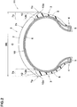
- FIG. 2 is a tyre meridian cross-sectional view of a bias tyre 11 for two-wheel vehicle (hereinafter, simply referred to as "tyre 11") under the normal state according to the second embodiment.
- tyre 11 a bias tyre 11 for two-wheel vehicle
- the bias tyre 11 includes the tread portion 2, the pair of the sidewall portions 3 extending inwardly in the tyre radial direction from the both ends of the tread portion 2, and the pair of bead portions 4 provided inwardly in the tyre radial direction of the pair of sidewall portions 3.
- the pair of bead cores 5 is disposed in the pair of bead portions 4, for example.
- the tyre 11, the same as the above-mentioned tyre 1, preferably includes the carcass 6 having a bias structure and the reinforcing layer 10 disposed outside in the tyre radial direction of the carcass 6 in the tread portion 2.
- the tyre 11 includes the tread rubber 7 forming the tread portion 2, and the pair of sidewall rubber portions 8 forming the pair of sidewall portions 3.
- the both end portions 7a of the tread rubber 7 are connected to the respective sidewall rubber portions 8 to form a pair of boundary surfaces 12 therebetween.
- outermost ends 12a in the tyre axial direction of the boundary surfaces 12 are located on an outer surface of the tyre and inwardly in the tyre radial direction of the respective tread edges Te.
- the tread rubber 7 always comes into contact with the ground and there is no risk that the sidewall rubber portions 8 come into contact with the ground.
- grip performance does not change suddenly since the sidewall rubber portions 8 do not come into contact with the ground during turning, and therefore steering stability performance can be improved.
- innermost ends 12b in the tyre axial direction of the boundary surfaces 12 are located outwardly in the tyre radial direction of the outermost ends 12a of the boundary surfaces 12.
- the innermost ends 12b of the boundary surfaces 12 are located outwardly in the tyre radial direction of the tread edges Te. In such a tyre 11, even if repeated load is applied near the boundary surfaces 12, the risk of cracking along the boundary surfaces 12 can be small, and thus durability can be improved.
- the boundary surfaces 12 are curved so as to be convex outwardly in the tyre radial direction. Since the ratio of the sidewall rubber portions 8 in the vicinity of the outer end portions 7a of the tread rubber 7 is large in such the boundary surfaces 12, it is possible to improve steering stability of the tyre 11 when turning at large camber angles.
- FIG. 3 is a tyre meridian cross-sectional view of a bias tyre 21 for two-wheel vehicle (hereinafter, simply referred to as "tyre 21") under the normal state according to the third embodiment. Note that elements having the same function as the above-described embodiment are denoted by the same reference numerals, and the description thereof may be omitted.
- the tyre 21 includes the tread portion 2, the pair of the sidewall portions 3 extending inwardly in the tyre radial direction from the both ends of the tread portion 2, and the pair of bead portions 4 provided inwardly in the tyre radial direction of the pair of sidewall portions 3.
- the pair of bead cores 5 is disposed in the pair of bead portions 4, for example.
- the tyre 21, the same as the above-mentioned tyre 1, preferably includes the carcass 6 having a bias structure and the reinforcing layer 10 disposed outside in the tyre radial direction of the carcass 6 in the tread portion 2.
- the tyre 21 includes the tread rubber 7 forming the tread surface 2s of the tread portion 2, and a toroidal rubber 22 disposed inwardly in the tyre radial direction of the tread rubber 7.
- the toroidal rubber 22 includes the pair of sidewall rubber portions 22a forming an outer surface of the pair of sidewall portions 3 and a connecting rubber portion 22b extending inward of the tread rubber 7 and connecting the pair of sidewall rubber portions 22a with each other.
- the tread rubber 7 is connected to the toroidal rubber to form a boundary surface 23 including a pair of axially outer boundary surfaces 23b. That is, the tread rubber 7 and the toroidal rubber 22 according to the third embodiment are made of different rubbers with one another.
- a rubber that has superior grip performance can be employed as the tread rubber 7, and a rubber that has superior absorbing performance can be employed as the toroidal rubber 22 including the sidewall rubber portions 22a.
- the tyre 21 according to the third embodiment can improve steering stability during turning.
- outermost ends 23a in the tyre axial direction of the boundary surface 23 are located on an outer surface of the tyre and inwardly in the tyre radial direction of the respective tread edges Te.
- a distance L3 in the tyre radial direction between the outermost ends 23a of the boundary surface 23 and the tread edges Te is equal to or less than 20 mm.
- the distance L3 is 20 mm or less, the outermost ends 23a of the boundary surface 23 can be located on an outer surface of the tyre 1 with less distortion during turning, and thus durability performance of the tyre 21 can be improved. From this point of view, the distance L3 is more preferably 15 mm or less.
- a height H in the tyre radial direction from a bead baseline BL to the outermost ends 23a of the boundary surface 23 is preferably equal to or more than 60%, more preferably equal to or more than 70% of the height HS in the tyre radial direction from the bead baseline BL to the pair of tread edges Te.
- the outermost ends 23a of the boundary surface 23 can be located on a region where less distortion occurs during turning of the outer surface of the tyre 21, and thus durability performance of the tyre 21 can be improved.
- the bead baseline BL is an axial line that corresponds to a location of a rim diameter of the standard wheel rim on which the tyre 21 is to be mounted.
- the height H of the outermost ends 23a of the boundary surface 23 is preferably equal to or less than 98%, more preferably equal to or less than 95% of the height HS of the tread edges Te.
- FIG. 4 is a development view of the tread portion 2 of the third embodiment.
- FIG. 3 is a cross-sectional view taken along line A-A of FIG. 4 .
- the tread portion 2 is provided with a plurality of grooves 24.
- the pattern and/or shape of the grooves 24 is not limited to those shown in FIG. 4 but can include one or more circumferential grooves extending continuously in the tyre circumferential direction, for example.
- the grooves 24 have a plurality of slip signs 25 for indicating wear condition of the tread portion 2.
- the slip signs 25 are portions protruding outward in the tyre radial direction from the groove bottoms of the grooves 24. When the tread portion 2 is worn and one or more slip signs 25 are exposed on the tread surface 2s, users can know that it is time to replace the tyre.
- the connecting rubber portion 22b is located inwardly in the tyre radial direction of an outer surface 25s of the slip sign 25 that is located nearest to the tyre equator C.
- Such a connecting rubber portion 22b is unlikely to be exposed to the tread surface 2s even if the area around the tyre equator C wears to the slip sign 25.
- grip performance does not change suddenly since the connecting rubber portion 22b do not come into contact with the ground even when the wear progresses. Therefore, steering stability of the tyre can be improved.
- a thickness t of the connecting rubber portion 22b is preferably equal to or more than 0.5 mm, more preferably equal to or more than 0.8 mm.
- the thickness t of the connecting rubber portion 22b is preferably equal to or less than 2.0 mm, more preferably equal to or less than 1.8 mm.
- Such a connecting rubber portion 22b is suitable for suppressing heat generation due to distortion of the tread rubber 7 at high-speed driving.
- the axially outer boundary surfaces 23b are curved so as to be convex inwardly in the tyre radial direction. Since the ratio of the sidewall rubber portions 22a in the vicinity of the outer boundary surfaces 23b is small in such the boundary surfaces 23b, it is possible to improve steering stability of the tyre 1 when turning at large camber angles.
- loss tangent tan ⁇ S of the sidewall rubber portions 22a and the connecting rubber portion 22b at 70 degrees C is smaller than loss tangent tan ⁇ T of the tread rubber 7 at 70 degrees C, same as the above-mentioned sidewall rubber portions 8.
- Such sidewall rubber portions 22a have excellent absorption performance and can improve riding comfort of the tyre 1.
- the sidewall rubber portions 22a and the connecting rubber portion 22b contain preferably 30 parts by mass or more, more preferably 40 parts by mass or more of natural rubber in 100 parts by mass of the rubber component. Such rubbers 22a and 22b can suppress the occurrence of cracks and improve durability performance of the tyre 21.
- the sidewall rubber portions 22a and the connecting rubber portion 22b may be formed integrally previously with one another.
- the sidewall rubber portions 22a and the connecting rubber portion 22b may be prepared separately and then be joined with one another to form the toroidal rubber 22.
- bias tyres for two-wheel vehicle having a structure shown in FIG. 1 and FIG. 2 were prototyped based on the specification of Table 1. Further, as a comparative example, a bias tyre for two-wheel vehicle in which the tread rubber and the sidewall rubber portions are formed integrally was prototyped. Then, using these prototype tyres, steering stability, ride comfort and durability were tested.
- the common specifications and test methods for each prototype tyre are as follows.
- Steering stability test A test rider drove a medium-sized scooter with each prototype tyre mounted on the rear wheel on a test course, and evaluated steering stability during turning in view of grip performance, feeling of ground contact, and the transient characteristics when turning by the rider's feeling.
- the test results are shown in Table 1 using an index with the comparative example as 100, wherein the larger the value, the better the steering stability.
- Ride comfort test A test rider drove the medium-sized scooter with each prototype tyre mounted on the rear wheel on a test course, and evaluated ride comfort by the rider's feeling.
- the test results are shown in Table 1 using an index with the comparative example as 100, wherein the larger the value, the better the ride comfort.
- Durability test The prototype tyres were put into an ozone chamber having a concentration of 50 pphm for 3 weeks to be subjected to ozone deterioration treatment. Then, these tyres were made to run 10,000 km on a drum tester under a load of 3.29 kN. After that, durability performance of each tyre was evaluated based on the crack occurrence rate of the sidewall portions. The test results are shown in Table 1 using an index with the comparative example as 100, wherein the larger the value, the better the durability.
- Table 1 shows the test results.
- bias tyres for two-wheel vehicle having a structure shown in FIG. 3 were prototyped based on the specification of Table 2. Further, as a comparative example, a bias tyre for two-wheel vehicle in which the tread rubber and the sidewall rubber portions are formed integrally was prototyped same as the first example. Then, using these prototype tyres, high-speed durability, steering stability, ride comfort and durability were tested.
- the common specifications and test methods for each prototype tyre are as follows.
- Steering stability test The test was conducted in the same way as the first example. The test results are shown in Table 2 using an index with the comparative example as 100, wherein the larger the value, the better the steering stability.
- Durability test The test was conducted in the same way as the first example. The test results are shown in Table 2 using an index with the comparative example as 100, wherein the larger the value, the better the durability.
- Table 2 shows the test results.
Landscapes
- Engineering & Computer Science (AREA)
- Mechanical Engineering (AREA)
- Tires In General (AREA)
Priority Applications (1)
| Application Number | Priority Date | Filing Date | Title |
|---|---|---|---|
| EP22152374.9A EP4005823B1 (fr) | 2020-02-19 | 2021-01-05 | Pneu à carcasse diagonale pour véhicule à deux roues |
Applications Claiming Priority (2)
| Application Number | Priority Date | Filing Date | Title |
|---|---|---|---|
| JP2020026432A JP7472526B2 (ja) | 2020-02-19 | 2020-02-19 | 二輪車用バイアスタイヤ |
| JP2020026433A JP7472527B2 (ja) | 2020-02-19 | 2020-02-19 | 二輪車用バイアスタイヤ |
Related Child Applications (2)
| Application Number | Title | Priority Date | Filing Date |
|---|---|---|---|
| EP22152374.9A Division EP4005823B1 (fr) | 2020-02-19 | 2021-01-05 | Pneu à carcasse diagonale pour véhicule à deux roues |
| EP22152374.9A Division-Into EP4005823B1 (fr) | 2020-02-19 | 2021-01-05 | Pneu à carcasse diagonale pour véhicule à deux roues |
Publications (2)
| Publication Number | Publication Date |
|---|---|
| EP3868574A1 true EP3868574A1 (fr) | 2021-08-25 |
| EP3868574B1 EP3868574B1 (fr) | 2025-05-14 |
Family
ID=74103980
Family Applications (2)
| Application Number | Title | Priority Date | Filing Date |
|---|---|---|---|
| EP21150269.5A Active EP3868574B1 (fr) | 2020-02-19 | 2021-01-05 | Pneu à carcasse diagonale pour véhicule à deux roues |
| EP22152374.9A Active EP4005823B1 (fr) | 2020-02-19 | 2021-01-05 | Pneu à carcasse diagonale pour véhicule à deux roues |
Family Applications After (1)
| Application Number | Title | Priority Date | Filing Date |
|---|---|---|---|
| EP22152374.9A Active EP4005823B1 (fr) | 2020-02-19 | 2021-01-05 | Pneu à carcasse diagonale pour véhicule à deux roues |
Country Status (2)
| Country | Link |
|---|---|
| EP (2) | EP3868574B1 (fr) |
| CN (1) | CN113276604B (fr) |
Citations (5)
| Publication number | Priority date | Publication date | Assignee | Title |
|---|---|---|---|---|
| JPS6094804A (ja) * | 1983-10-31 | 1985-05-28 | Yokohama Rubber Co Ltd:The | 二輪自動車用タイヤ |
| JP2000185511A (ja) | 1998-12-22 | 2000-07-04 | Sumitomo Rubber Ind Ltd | 自動二輪車用バイアスタイヤ |
| JP2002337512A (ja) * | 2001-05-22 | 2002-11-27 | Sumitomo Rubber Ind Ltd | 自動二輪車用ラジアルタイヤ |
| US20080149248A1 (en) * | 2006-12-21 | 2008-06-26 | The Goodyear Tire & Rubber Company | Pneumatic tire |
| EP2722196A2 (fr) * | 2012-10-22 | 2014-04-23 | The Goodyear Tire & Rubber Company | Pneu de moto présentant une construction hybride |
Family Cites Families (14)
| Publication number | Priority date | Publication date | Assignee | Title |
|---|---|---|---|---|
| JP3287774B2 (ja) * | 1996-10-17 | 2002-06-04 | 住友ゴム工業株式会社 | 自動二輪車用タイヤ |
| JP3996273B2 (ja) * | 1998-07-06 | 2007-10-24 | 住友ゴム工業株式会社 | 自動二輪車用ラジアルタイヤ |
| JP2001191730A (ja) * | 1999-12-29 | 2001-07-17 | Sumitomo Rubber Ind Ltd | 自動二輪車用タイヤ |
| JP4040893B2 (ja) * | 2002-03-22 | 2008-01-30 | 株式会社ブリヂストン | スクーター用空気入りラジアルタイヤおよびスクーター |
| JP5020595B2 (ja) * | 2006-10-24 | 2012-09-05 | 住友ゴム工業株式会社 | 二輪車用タイヤ |
| JP2008273422A (ja) * | 2007-05-01 | 2008-11-13 | Sumitomo Rubber Ind Ltd | 自動二輪車用タイヤ |
| JP5091599B2 (ja) * | 2007-09-14 | 2012-12-05 | 住友ゴム工業株式会社 | 空気入りタイヤ及びその製造方法 |
| JP5616878B2 (ja) * | 2011-12-05 | 2014-10-29 | 住友ゴム工業株式会社 | 自動二輪車用タイヤ |
| JP6053550B2 (ja) * | 2013-02-18 | 2016-12-27 | 住友ゴム工業株式会社 | 空気入りタイヤ |
| JP5905038B2 (ja) * | 2013-03-15 | 2016-04-20 | 住友ゴム工業株式会社 | 不整地用モーターサイクルタイヤ |
| JP6144991B2 (ja) * | 2013-08-02 | 2017-06-07 | 住友ゴム工業株式会社 | 自動二輪車用タイヤ |
| JP2015033982A (ja) * | 2013-08-09 | 2015-02-19 | 住友ゴム工業株式会社 | 自動二輪車用タイヤ |
| CN206106822U (zh) * | 2016-08-26 | 2017-04-19 | 四川远星橡胶有限责任公司 | 一种摩托车用轮胎 |
| CN106114070A (zh) * | 2016-08-26 | 2016-11-16 | 四川远星橡胶有限责任公司 | 一种适用于越野摩托车的轮胎 |
-
2021
- 2021-01-05 EP EP21150269.5A patent/EP3868574B1/fr active Active
- 2021-01-05 EP EP22152374.9A patent/EP4005823B1/fr active Active
- 2021-01-28 CN CN202110118044.4A patent/CN113276604B/zh active Active
Patent Citations (5)
| Publication number | Priority date | Publication date | Assignee | Title |
|---|---|---|---|---|
| JPS6094804A (ja) * | 1983-10-31 | 1985-05-28 | Yokohama Rubber Co Ltd:The | 二輪自動車用タイヤ |
| JP2000185511A (ja) | 1998-12-22 | 2000-07-04 | Sumitomo Rubber Ind Ltd | 自動二輪車用バイアスタイヤ |
| JP2002337512A (ja) * | 2001-05-22 | 2002-11-27 | Sumitomo Rubber Ind Ltd | 自動二輪車用ラジアルタイヤ |
| US20080149248A1 (en) * | 2006-12-21 | 2008-06-26 | The Goodyear Tire & Rubber Company | Pneumatic tire |
| EP2722196A2 (fr) * | 2012-10-22 | 2014-04-23 | The Goodyear Tire & Rubber Company | Pneu de moto présentant une construction hybride |
Also Published As
| Publication number | Publication date |
|---|---|
| EP4005823A1 (fr) | 2022-06-01 |
| EP4005823B1 (fr) | 2023-10-04 |
| EP3868574B1 (fr) | 2025-05-14 |
| CN113276604A (zh) | 2021-08-20 |
| CN113276604B (zh) | 2025-02-25 |
Similar Documents
| Publication | Publication Date | Title |
|---|---|---|
| EP2628612B1 (fr) | Pneu | |
| EP2206612B1 (fr) | Pneu pour motocyclette | |
| EP1923235B1 (fr) | Pneu hors route | |
| EP3050721A1 (fr) | Pneu de motocyclette | |
| EP3730314B1 (fr) | Pneu pour motocyclettes et jeu de pneus pour motocyclettes | |
| EP2186653A1 (fr) | Pneu pour véhicule à moteur à deux roues et son procédé de fabrication | |
| EP4043241B1 (fr) | Pneumatique de motocyclette | |
| EP3530487B1 (fr) | Pneu de véhicule à deux roues | |
| JP5138923B2 (ja) | 自動二輪車用タイヤ | |
| EP3521068A1 (fr) | Pneu de véhicule à deux roues | |
| EP4005824B1 (fr) | Pneumatique de motocyclette | |
| EP4070968B1 (fr) | Pneumatique de motocyclette | |
| EP4253087B1 (fr) | Pneumatique pour moto | |
| EP4032725B1 (fr) | Pneumatique de motocyclette | |
| EP4005823B1 (fr) | Pneu à carcasse diagonale pour véhicule à deux roues | |
| EP4091837B1 (fr) | Pneumatique de motocyclette | |
| EP3970992B1 (fr) | Pneumatique de motocyclette | |
| EP3552843B1 (fr) | Pneu de véhicule à deux roues | |
| EP3944967B1 (fr) | Pneumatique de motocyclette | |
| EP4234271B1 (fr) | Ensemble de pneumatiques pour moto | |
| EP4253096B1 (fr) | Pneu de motocyclette | |
| JP7472527B2 (ja) | 二輪車用バイアスタイヤ | |
| EP4098460A1 (fr) | Pneu pour usage intensif | |
| JP2021130380A (ja) | 二輪車用バイアスタイヤ |
Legal Events
| Date | Code | Title | Description |
|---|---|---|---|
| PUAI | Public reference made under article 153(3) epc to a published international application that has entered the european phase |
Free format text: ORIGINAL CODE: 0009012 |
|
| STAA | Information on the status of an ep patent application or granted ep patent |
Free format text: STATUS: THE APPLICATION HAS BEEN PUBLISHED |
|
| AK | Designated contracting states |
Kind code of ref document: A1 Designated state(s): AL AT BE BG CH CY CZ DE DK EE ES FI FR GB GR HR HU IE IS IT LI LT LU LV MC MK MT NL NO PL PT RO RS SE SI SK SM TR |
|
| STAA | Information on the status of an ep patent application or granted ep patent |
Free format text: STATUS: REQUEST FOR EXAMINATION WAS MADE |
|
| 17P | Request for examination filed |
Effective date: 20220121 |
|
| RBV | Designated contracting states (corrected) |
Designated state(s): AL AT BE BG CH CY CZ DE DK EE ES FI FR GB GR HR HU IE IS IT LI LT LU LV MC MK MT NL NO PL PT RO RS SE SI SK SM TR |
|
| STAA | Information on the status of an ep patent application or granted ep patent |
Free format text: STATUS: EXAMINATION IS IN PROGRESS |
|
| 17Q | First examination report despatched |
Effective date: 20221021 |
|
| P01 | Opt-out of the competence of the unified patent court (upc) registered |
Effective date: 20230510 |
|
| GRAP | Despatch of communication of intention to grant a patent |
Free format text: ORIGINAL CODE: EPIDOSNIGR1 |
|
| STAA | Information on the status of an ep patent application or granted ep patent |
Free format text: STATUS: GRANT OF PATENT IS INTENDED |
|
| RIC1 | Information provided on ipc code assigned before grant |
Ipc: B60C 13/00 20060101ALI20241104BHEP Ipc: B60C 11/24 20060101ALI20241104BHEP Ipc: B60C 9/06 20060101AFI20241104BHEP |
|
| INTG | Intention to grant announced |
Effective date: 20241210 |
|
| GRAS | Grant fee paid |
Free format text: ORIGINAL CODE: EPIDOSNIGR3 |
|
| GRAA | (expected) grant |
Free format text: ORIGINAL CODE: 0009210 |
|
| STAA | Information on the status of an ep patent application or granted ep patent |
Free format text: STATUS: THE PATENT HAS BEEN GRANTED |
|
| AK | Designated contracting states |
Kind code of ref document: B1 Designated state(s): AL AT BE BG CH CY CZ DE DK EE ES FI FR GB GR HR HU IE IS IT LI LT LU LV MC MK MT NL NO PL PT RO RS SE SI SK SM TR |
|
| REG | Reference to a national code |
Ref country code: GB Ref legal event code: FG4D |
|
| REG | Reference to a national code |
Ref country code: CH Ref legal event code: EP |
|
| REG | Reference to a national code |
Ref country code: IE Ref legal event code: FG4D |
|
| REG | Reference to a national code |
Ref country code: DE Ref legal event code: R096 Ref document number: 602021030655 Country of ref document: DE |
|
| REG | Reference to a national code |
Ref country code: NL Ref legal event code: MP Effective date: 20250514 |
|
| PG25 | Lapsed in a contracting state [announced via postgrant information from national office to epo] |
Ref country code: PT Free format text: LAPSE BECAUSE OF FAILURE TO SUBMIT A TRANSLATION OF THE DESCRIPTION OR TO PAY THE FEE WITHIN THE PRESCRIBED TIME-LIMIT Effective date: 20250915 Ref country code: FI Free format text: LAPSE BECAUSE OF FAILURE TO SUBMIT A TRANSLATION OF THE DESCRIPTION OR TO PAY THE FEE WITHIN THE PRESCRIBED TIME-LIMIT Effective date: 20250514 Ref country code: ES Free format text: LAPSE BECAUSE OF FAILURE TO SUBMIT A TRANSLATION OF THE DESCRIPTION OR TO PAY THE FEE WITHIN THE PRESCRIBED TIME-LIMIT Effective date: 20250514 |
|
| REG | Reference to a national code |
Ref country code: LT Ref legal event code: MG9D |
|
| PG25 | Lapsed in a contracting state [announced via postgrant information from national office to epo] |
Ref country code: GR Free format text: LAPSE BECAUSE OF FAILURE TO SUBMIT A TRANSLATION OF THE DESCRIPTION OR TO PAY THE FEE WITHIN THE PRESCRIBED TIME-LIMIT Effective date: 20250815 Ref country code: NO Free format text: LAPSE BECAUSE OF FAILURE TO SUBMIT A TRANSLATION OF THE DESCRIPTION OR TO PAY THE FEE WITHIN THE PRESCRIBED TIME-LIMIT Effective date: 20250814 |
|
| PG25 | Lapsed in a contracting state [announced via postgrant information from national office to epo] |
Ref country code: PL Free format text: LAPSE BECAUSE OF FAILURE TO SUBMIT A TRANSLATION OF THE DESCRIPTION OR TO PAY THE FEE WITHIN THE PRESCRIBED TIME-LIMIT Effective date: 20250514 Ref country code: NL Free format text: LAPSE BECAUSE OF FAILURE TO SUBMIT A TRANSLATION OF THE DESCRIPTION OR TO PAY THE FEE WITHIN THE PRESCRIBED TIME-LIMIT Effective date: 20250514 |
|
| REG | Reference to a national code |
Ref country code: AT Ref legal event code: MK05 Ref document number: 1794500 Country of ref document: AT Kind code of ref document: T Effective date: 20250514 |
|
| PG25 | Lapsed in a contracting state [announced via postgrant information from national office to epo] |
Ref country code: BG Free format text: LAPSE BECAUSE OF FAILURE TO SUBMIT A TRANSLATION OF THE DESCRIPTION OR TO PAY THE FEE WITHIN THE PRESCRIBED TIME-LIMIT Effective date: 20250514 |
|
| PG25 | Lapsed in a contracting state [announced via postgrant information from national office to epo] |
Ref country code: HR Free format text: LAPSE BECAUSE OF FAILURE TO SUBMIT A TRANSLATION OF THE DESCRIPTION OR TO PAY THE FEE WITHIN THE PRESCRIBED TIME-LIMIT Effective date: 20250514 |
|
| PG25 | Lapsed in a contracting state [announced via postgrant information from national office to epo] |
Ref country code: AT Free format text: LAPSE BECAUSE OF FAILURE TO SUBMIT A TRANSLATION OF THE DESCRIPTION OR TO PAY THE FEE WITHIN THE PRESCRIBED TIME-LIMIT Effective date: 20250514 |
|
| PG25 | Lapsed in a contracting state [announced via postgrant information from national office to epo] |
Ref country code: RS Free format text: LAPSE BECAUSE OF FAILURE TO SUBMIT A TRANSLATION OF THE DESCRIPTION OR TO PAY THE FEE WITHIN THE PRESCRIBED TIME-LIMIT Effective date: 20250814 |
|
| PG25 | Lapsed in a contracting state [announced via postgrant information from national office to epo] |
Ref country code: IS Free format text: LAPSE BECAUSE OF FAILURE TO SUBMIT A TRANSLATION OF THE DESCRIPTION OR TO PAY THE FEE WITHIN THE PRESCRIBED TIME-LIMIT Effective date: 20250914 |
|
| PG25 | Lapsed in a contracting state [announced via postgrant information from national office to epo] |
Ref country code: LV Free format text: LAPSE BECAUSE OF FAILURE TO SUBMIT A TRANSLATION OF THE DESCRIPTION OR TO PAY THE FEE WITHIN THE PRESCRIBED TIME-LIMIT Effective date: 20250514 |
|
| PG25 | Lapsed in a contracting state [announced via postgrant information from national office to epo] |
Ref country code: SM Free format text: LAPSE BECAUSE OF FAILURE TO SUBMIT A TRANSLATION OF THE DESCRIPTION OR TO PAY THE FEE WITHIN THE PRESCRIBED TIME-LIMIT Effective date: 20250514 Ref country code: DK Free format text: LAPSE BECAUSE OF FAILURE TO SUBMIT A TRANSLATION OF THE DESCRIPTION OR TO PAY THE FEE WITHIN THE PRESCRIBED TIME-LIMIT Effective date: 20250514 |
|
| PG25 | Lapsed in a contracting state [announced via postgrant information from national office to epo] |
Ref country code: CZ Free format text: LAPSE BECAUSE OF FAILURE TO SUBMIT A TRANSLATION OF THE DESCRIPTION OR TO PAY THE FEE WITHIN THE PRESCRIBED TIME-LIMIT Effective date: 20250514 |
|
| PG25 | Lapsed in a contracting state [announced via postgrant information from national office to epo] |
Ref country code: EE Free format text: LAPSE BECAUSE OF FAILURE TO SUBMIT A TRANSLATION OF THE DESCRIPTION OR TO PAY THE FEE WITHIN THE PRESCRIBED TIME-LIMIT Effective date: 20250514 |
|
| PG25 | Lapsed in a contracting state [announced via postgrant information from national office to epo] |
Ref country code: RO Free format text: LAPSE BECAUSE OF FAILURE TO SUBMIT A TRANSLATION OF THE DESCRIPTION OR TO PAY THE FEE WITHIN THE PRESCRIBED TIME-LIMIT Effective date: 20250514 Ref country code: SK Free format text: LAPSE BECAUSE OF FAILURE TO SUBMIT A TRANSLATION OF THE DESCRIPTION OR TO PAY THE FEE WITHIN THE PRESCRIBED TIME-LIMIT Effective date: 20250514 |
|
| PG25 | Lapsed in a contracting state [announced via postgrant information from national office to epo] |
Ref country code: IT Free format text: LAPSE BECAUSE OF FAILURE TO SUBMIT A TRANSLATION OF THE DESCRIPTION OR TO PAY THE FEE WITHIN THE PRESCRIBED TIME-LIMIT Effective date: 20250514 |
|
| REG | Reference to a national code |
Ref country code: DE Ref legal event code: R097 Ref document number: 602021030655 Country of ref document: DE |
|
| PLBE | No opposition filed within time limit |
Free format text: ORIGINAL CODE: 0009261 |
|
| STAA | Information on the status of an ep patent application or granted ep patent |
Free format text: STATUS: NO OPPOSITION FILED WITHIN TIME LIMIT |
|
| REG | Reference to a national code |
Ref country code: CH Ref legal event code: L10 Free format text: ST27 STATUS EVENT CODE: U-0-0-L10-L00 (AS PROVIDED BY THE NATIONAL OFFICE) Effective date: 20260325 |
|
| PGFP | Annual fee paid to national office [announced via postgrant information from national office to epo] |
Ref country code: DE Payment date: 20260328 Year of fee payment: 6 |
|
| PGFP | Annual fee paid to national office [announced via postgrant information from national office to epo] |
Ref country code: FR Payment date: 20260123 Year of fee payment: 6 |
|
| 26N | No opposition filed |
Effective date: 20260217 |