EP3868593B1 - Axe de transmission de puissance pour véhicule, et véhicule - Google Patents
Axe de transmission de puissance pour véhicule, et véhicule Download PDFInfo
- Publication number
- EP3868593B1 EP3868593B1 EP19873723.1A EP19873723A EP3868593B1 EP 3868593 B1 EP3868593 B1 EP 3868593B1 EP 19873723 A EP19873723 A EP 19873723A EP 3868593 B1 EP3868593 B1 EP 3868593B1
- Authority
- EP
- European Patent Office
- Prior art keywords
- shaft
- vehicle
- segment
- traction
- flange
- Prior art date
- Legal status (The legal status is an assumption and is not a legal conclusion. Google has not performed a legal analysis and makes no representation as to the accuracy of the status listed.)
- Active
Links
Images



Classifications
-
- B—PERFORMING OPERATIONS; TRANSPORTING
- B60—VEHICLES IN GENERAL
- B60K—ARRANGEMENT OR MOUNTING OF PROPULSION UNITS OR OF TRANSMISSIONS IN VEHICLES; ARRANGEMENT OR MOUNTING OF PLURAL DIVERSE PRIME-MOVERS IN VEHICLES; AUXILIARY DRIVES FOR VEHICLES; INSTRUMENTATION OR DASHBOARDS FOR VEHICLES; ARRANGEMENTS IN CONNECTION WITH COOLING, AIR INTAKE, GAS EXHAUST OR FUEL SUPPLY OF PROPULSION UNITS IN VEHICLES
- B60K17/00—Arrangement or mounting of transmissions in vehicles
- B60K17/36—Arrangement or mounting of transmissions in vehicles for driving tandem wheels
-
- B—PERFORMING OPERATIONS; TRANSPORTING
- B60—VEHICLES IN GENERAL
- B60B—VEHICLE WHEELS; CASTORS; AXLES FOR WHEELS OR CASTORS; INCREASING WHEEL ADHESION
- B60B35/00—Axle units; Parts thereof ; Arrangements for lubrication of axles
- B60B35/12—Torque-transmitting axles
- B60B35/14—Torque-transmitting axles composite or split, e.g. half- axles; Couplings between axle parts or sections
-
- B—PERFORMING OPERATIONS; TRANSPORTING
- B60—VEHICLES IN GENERAL
- B60K—ARRANGEMENT OR MOUNTING OF PROPULSION UNITS OR OF TRANSMISSIONS IN VEHICLES; ARRANGEMENT OR MOUNTING OF PLURAL DIVERSE PRIME-MOVERS IN VEHICLES; AUXILIARY DRIVES FOR VEHICLES; INSTRUMENTATION OR DASHBOARDS FOR VEHICLES; ARRANGEMENTS IN CONNECTION WITH COOLING, AIR INTAKE, GAS EXHAUST OR FUEL SUPPLY OF PROPULSION UNITS IN VEHICLES
- B60K17/00—Arrangement or mounting of transmissions in vehicles
- B60K17/02—Arrangement or mounting of transmissions in vehicles characterised by arrangement, location, or kind of clutch
-
- B—PERFORMING OPERATIONS; TRANSPORTING
- B60—VEHICLES IN GENERAL
- B60K—ARRANGEMENT OR MOUNTING OF PROPULSION UNITS OR OF TRANSMISSIONS IN VEHICLES; ARRANGEMENT OR MOUNTING OF PLURAL DIVERSE PRIME-MOVERS IN VEHICLES; AUXILIARY DRIVES FOR VEHICLES; INSTRUMENTATION OR DASHBOARDS FOR VEHICLES; ARRANGEMENTS IN CONNECTION WITH COOLING, AIR INTAKE, GAS EXHAUST OR FUEL SUPPLY OF PROPULSION UNITS IN VEHICLES
- B60K17/00—Arrangement or mounting of transmissions in vehicles
- B60K17/22—Arrangement or mounting of transmissions in vehicles characterised by arrangement, location, or type of main drive shafting, e.g. cardan shaft
-
- B—PERFORMING OPERATIONS; TRANSPORTING
- B60—VEHICLES IN GENERAL
- B60K—ARRANGEMENT OR MOUNTING OF PROPULSION UNITS OR OF TRANSMISSIONS IN VEHICLES; ARRANGEMENT OR MOUNTING OF PLURAL DIVERSE PRIME-MOVERS IN VEHICLES; AUXILIARY DRIVES FOR VEHICLES; INSTRUMENTATION OR DASHBOARDS FOR VEHICLES; ARRANGEMENTS IN CONNECTION WITH COOLING, AIR INTAKE, GAS EXHAUST OR FUEL SUPPLY OF PROPULSION UNITS IN VEHICLES
- B60K17/00—Arrangement or mounting of transmissions in vehicles
- B60K17/34—Arrangement or mounting of transmissions in vehicles for driving both front and rear wheels, e.g. four wheel drive vehicles
- B60K17/348—Arrangement or mounting of transmissions in vehicles for driving both front and rear wheels, e.g. four wheel drive vehicles having differential means for driving one set of wheels, e.g. the front, at one speed and the other set, e.g. the rear, at a different speed
- B60K17/35—Arrangement or mounting of transmissions in vehicles for driving both front and rear wheels, e.g. four wheel drive vehicles having differential means for driving one set of wheels, e.g. the front, at one speed and the other set, e.g. the rear, at a different speed including arrangements for suppressing or influencing the power transfer, e.g. viscous clutches
-
- B—PERFORMING OPERATIONS; TRANSPORTING
- B60—VEHICLES IN GENERAL
- B60K—ARRANGEMENT OR MOUNTING OF PROPULSION UNITS OR OF TRANSMISSIONS IN VEHICLES; ARRANGEMENT OR MOUNTING OF PLURAL DIVERSE PRIME-MOVERS IN VEHICLES; AUXILIARY DRIVES FOR VEHICLES; INSTRUMENTATION OR DASHBOARDS FOR VEHICLES; ARRANGEMENTS IN CONNECTION WITH COOLING, AIR INTAKE, GAS EXHAUST OR FUEL SUPPLY OF PROPULSION UNITS IN VEHICLES
- B60K23/00—Arrangement or mounting of control devices for vehicle transmissions, or parts thereof, not otherwise provided for
- B60K23/08—Arrangement or mounting of control devices for vehicle transmissions, or parts thereof, not otherwise provided for for changing number of driven wheels, for switching from driving one axle to driving two or more axles
-
- B—PERFORMING OPERATIONS; TRANSPORTING
- B60—VEHICLES IN GENERAL
- B60K—ARRANGEMENT OR MOUNTING OF PROPULSION UNITS OR OF TRANSMISSIONS IN VEHICLES; ARRANGEMENT OR MOUNTING OF PLURAL DIVERSE PRIME-MOVERS IN VEHICLES; AUXILIARY DRIVES FOR VEHICLES; INSTRUMENTATION OR DASHBOARDS FOR VEHICLES; ARRANGEMENTS IN CONNECTION WITH COOLING, AIR INTAKE, GAS EXHAUST OR FUEL SUPPLY OF PROPULSION UNITS IN VEHICLES
- B60K23/00—Arrangement or mounting of control devices for vehicle transmissions, or parts thereof, not otherwise provided for
- B60K23/08—Arrangement or mounting of control devices for vehicle transmissions, or parts thereof, not otherwise provided for for changing number of driven wheels, for switching from driving one axle to driving two or more axles
- B60K23/0808—Arrangement or mounting of control devices for vehicle transmissions, or parts thereof, not otherwise provided for for changing number of driven wheels, for switching from driving one axle to driving two or more axles for varying torque distribution between driven axles, e.g. by transfer clutch
- B60K2023/0816—Arrangement or mounting of control devices for vehicle transmissions, or parts thereof, not otherwise provided for for changing number of driven wheels, for switching from driving one axle to driving two or more axles for varying torque distribution between driven axles, e.g. by transfer clutch for varying front-rear torque distribution with a central differential
- B60K2023/0833—Arrangement or mounting of control devices for vehicle transmissions, or parts thereof, not otherwise provided for for changing number of driven wheels, for switching from driving one axle to driving two or more axles for varying torque distribution between driven axles, e.g. by transfer clutch for varying front-rear torque distribution with a central differential for adding torque to the rear wheels
-
- B—PERFORMING OPERATIONS; TRANSPORTING
- B60—VEHICLES IN GENERAL
- B60K—ARRANGEMENT OR MOUNTING OF PROPULSION UNITS OR OF TRANSMISSIONS IN VEHICLES; ARRANGEMENT OR MOUNTING OF PLURAL DIVERSE PRIME-MOVERS IN VEHICLES; AUXILIARY DRIVES FOR VEHICLES; INSTRUMENTATION OR DASHBOARDS FOR VEHICLES; ARRANGEMENTS IN CONNECTION WITH COOLING, AIR INTAKE, GAS EXHAUST OR FUEL SUPPLY OF PROPULSION UNITS IN VEHICLES
- B60K23/00—Arrangement or mounting of control devices for vehicle transmissions, or parts thereof, not otherwise provided for
- B60K23/08—Arrangement or mounting of control devices for vehicle transmissions, or parts thereof, not otherwise provided for for changing number of driven wheels, for switching from driving one axle to driving two or more axles
- B60K2023/085—Arrangement or mounting of control devices for vehicle transmissions, or parts thereof, not otherwise provided for for changing number of driven wheels, for switching from driving one axle to driving two or more axles automatically actuated
- B60K2023/0866—Arrangement or mounting of control devices for vehicle transmissions, or parts thereof, not otherwise provided for for changing number of driven wheels, for switching from driving one axle to driving two or more axles automatically actuated with hydraulic means only
-
- B—PERFORMING OPERATIONS; TRANSPORTING
- B60—VEHICLES IN GENERAL
- B60Y—INDEXING SCHEME RELATING TO ASPECTS CROSS-CUTTING VEHICLE TECHNOLOGY
- B60Y2200/00—Type of vehicle
- B60Y2200/10—Road Vehicles
- B60Y2200/14—Trucks; Load vehicles, Busses
-
- B—PERFORMING OPERATIONS; TRANSPORTING
- B60—VEHICLES IN GENERAL
- B60Y—INDEXING SCHEME RELATING TO ASPECTS CROSS-CUTTING VEHICLE TECHNOLOGY
- B60Y2400/00—Special features of vehicle units
- B60Y2400/40—Actuators for moving a controlled member
- B60Y2400/406—Hydraulic actuators
-
- B—PERFORMING OPERATIONS; TRANSPORTING
- B60—VEHICLES IN GENERAL
- B60Y—INDEXING SCHEME RELATING TO ASPECTS CROSS-CUTTING VEHICLE TECHNOLOGY
- B60Y2400/00—Special features of vehicle units
- B60Y2400/40—Actuators for moving a controlled member
- B60Y2400/408—Pneumatic actuators
-
- B—PERFORMING OPERATIONS; TRANSPORTING
- B60—VEHICLES IN GENERAL
- B60Y—INDEXING SCHEME RELATING TO ASPECTS CROSS-CUTTING VEHICLE TECHNOLOGY
- B60Y2400/00—Special features of vehicle units
- B60Y2400/42—Clutches or brakes
- B60Y2400/421—Dog type clutches or brakes
Definitions
- This invention refers, in a general sense, to a propeller shaft of an automotive vehicle, which has a coupling and decoupling system to allow the selection of the vehicle's traction type, transmitting or not the power to the subsequent shaft.
- This invention also refers to an automotive vehicle comprising the present propeller shaft.
- automotive vehicles and particularly those intended for the transportation of goods, such as trucks, are usually pulled by their rear shaft having a powertrain formed by the engine and gearbox mounted at the front of the vehicle.
- the connection between the powertrain and the traction wheels is formed by a shaft, commonly called the cardan shaft, which, on the one hand, is connected to the output of the powertrain, usually the gearbox and, on the other hand, is connected to the differential of the shaft that is responsible for transmitting the power to the wheels.
- the vehicle may have a 6 ⁇ 2 or 6 ⁇ 4 traction configuration, i.e., of the six wheels of the vehicle, only two are pulled, usually the two wheels of the first rear shaft, or the four wheels of the two rear shafts are pulled.
- 6 ⁇ 2 or 6 ⁇ 4 traction configuration i.e., of the six wheels of the vehicle, only two are pulled, usually the two wheels of the first rear shaft, or the four wheels of the two rear shafts are pulled.
- they may also have an 8 ⁇ 4 or even 6 ⁇ 6 or 8 ⁇ 8 traction configuration.
- the traction configuration is, for example, a 6 ⁇ 2 configuration
- one of the rear shafts, the one not pulled can potentially be suspended and thus achieve a reduction in fuel consumption and tire wear. This is possible using some solutions that are already known, and where an air bag is generally used to suspend the shaft, thus taking advantage of the compressed air line fitted in these models of vehicles.
- a propeller shaft for a motor vehicle particularly those used for transporting loads with a traction configuration of 6 ⁇ 4 or 8 ⁇ 4, where said propeller shaft is equipped with technical, constructive and functional characteristics designed and developed to allow for the decoupling and coupling of at least one of the traction shafts in order to eliminate the problems, limitations and inconveniences of the solutions previously known to the state of the art, and as summarized above.
- Another aim of this invention is to provide a vehicle, such as those used for the transportation of loads, which is configured with traction of the 6 ⁇ 4 or 8 ⁇ 4 type, and equipped with at least one propeller shaft as mentioned above, installed in place of the conventional cardan shaft of the vehicle, allowing for the selection of the type of traction.
- the present invention refers to a propeller shaft and a vehicle as claimed in the appended set of claims.
- Figure 1 schematically represents a vehicle (V) intended for the transportation of cargo or goods, such as a truck known to the state of the art.
- This vehicle (V) as schematically represented in Figure 1 , may be, for example, a model manufactured and marketed by CNH Industrial N. V.
- the vehicle (V) comprises a control and operation cab (C) under which are provided a transmission powertrain (M), such as a combustion engine associated with a gearbox, which are mounted on a chassis (E) supported by a front shaft (TD), a first rear shaft (T1) and a second rear shaft (T2).
- a transmission powertrain such as a combustion engine associated with a gearbox
- TD front shaft
- T1 first rear shaft
- T2 second rear shaft
- these rear shafts (T1, T2) are pulled and, thus, will potentially be indicated as the first traction shaft (T1) and the second traction shaft (T2).
- the drive assembly (M) which is formed of the gearbox within which are arranged a series of gears and other components responsible for transmitting the power generated in the engine and, from which extends a first cardan shaft 1 to a first differential of the first traction shaft (T1) and, from the differential of the first traction shaft (T1), extends a second cardan shaft 2 to the differential of the second traction shaft (T2).
- the power is generally divided equally between the first and second differentials to the wheels of the first (T1) and second (T2) traction shafts.
- the differentials transmit the power to the wheels of each shaft in a normal way using a crown/pinion system and epicycloidal gears, which is already well known to persons skilled in the art and, thus, will not be explored in this case.
- other details of the vehicle (V) are represented in a schematic way and do not require further explanation, since they are known in conventional cargo transport vehicles.
- the present invention aims, precisely, to allow for the coupling or decoupling, selectively and according to the interests of the driver, of the second differential from the second traction shaft (T2), transforming the traction configuration from 6x4 to a 6x2 traction configuration.
- T2 second traction shaft
- the invention can obviously be used in any traction configuration where one wishes to activate or deactivate a second traction shaft, such as a 4 ⁇ 4 / 4 ⁇ 2, 8 ⁇ 4 / 8 ⁇ 2 traction configuration, etc.
- a transmission shaft 10 is shown, such as for coupling in a cardan shaft or replacing a conventional cardan shaft, which is specifically mounted between the first traction shaft (T1) and the second traction shaft (T2) of a vehicle (V).
- the shaft 10 can be mounted between the differentials of two rear traction shafts of a vehicle comprising, for example, a 6 ⁇ 4 traction configuration, or even replace the second cardan shaft 2.
- first rear shaft (T1) and the second rear shaft (T2) can have different assembly heights or can also be mounted to the suspension of the vehicle, being subject to oscillations in height and, consequently, at a distance from each other, crossheads 3 and 4 are provided at the ends of the shaft 10, which form the mechanical connection with the rest of the transmission powertrain of the vehicle.
- the shaft 10 comprises an assembly 5 of two concentric toothed shafts, which allow for the compensation of the distance that may exist between the first traction shaft (T1) and the second traction shaft (T2).
- both the crossheads 3 and 4, and the assembly 5 are mechanical constructions used in cardan shafts that are widely known and used in the state of the art, and can thus be replaced by any equivalent mechanical constructions, such as homokinetic joints or flanges associated with screws and nuts, in cases where the coupling is mounted on a long cardan shaft.
- the decision to choose crossheads, homokinetic joints or other mechanical construction elements does not alter the technical effects foreseen for the present invention.
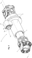
- the present invention refers to a new propeller shaft 10 comprising a first shaft segment 12, which can be mounted on a power output, and a second shaft segment 13, which can be mounted on a power input to receive the power coming from the first shaft segment 12.
- Both shaft segments 12, 13 are concentrically mounted within a housing 11, so that the first shaft segment 12 can be rotated independently in relation to the second shaft segment 13, where this first shaft segment 12 comprises, on the one hand, a power input and, on the other hand, is mounted concentrically with the second shaft segment 13.
- the second shaft segment 13 also has, on one side, a toothed face (16) to receive a power input and, on the other side, it has a power output.
- first 12 and second 13 shaft segments are coupled and decoupled selectively by means of a flange 15, which is mounted concentrically on the first shaft segment and comprises a toothed face for the respective coupling with the toothed face of the second shaft segment. Furthermore, this flange 15 can move between a coupled and uncoupled position due to the coaxial displacement along the said first shaft segment 12.
- the said flange 15 is driven by a coupler 14 formed of an actuator 14a that possesses a shaft 18c equipped with a means of return 20, and a fork 17 connected to said flange 15 provided with a groove in its internal diameter for connection with a grooved part 12a provided for in the first shaft segment 12, and teeth 15a on its lateral face to enable the connection with the teeth 16a arranged on the toothed face 16 of the second shaft segment 13.
- the propeller shaft 10, according to the present invention can be installed in place of the second cardan shaft 2, between the first traction shaft (T1) and the second traction shaft (T2) of said vehicle (V).
- the first shaft segment 12 is mounted next at a power output deriving from the first cardan shaft 1
- the second shaft segment 13 is mounted on the power input, for example, on the differential of the second traction shaft (T2), said shaft segments 12, 13 being selectively connected through said coupler 14 which is responsible for blocking and transmitting the power between the shaft segments 12, 13.
- said housing 11 comprises sealant elements 8 to securely hold a lubricating and cooling fluid in contact with said shaft segments 12, 13, as well as with the actuator 14.
- first shaft segment 12 can be mounted on a power output and the second shaft segment 13 can be mounted on a power input
- configuration may be reversed, i.e., the first shaft segment 12 can be mounted on a power input and the second shaft segment 13 can be mounted on a power output without any prejudice or difference in relation to the technical effect achieved by the present invention.
- said toothed face 16 may be a fixed flange that is provided with a grooved surface on its inner diameter for connection with a respective grooved part 13a positioned at the end of the second shaft segment 13.
- the toothed face 16 or said fixed flange possesses teeth 16a on its lateral face to enable the connection with the teeth 15a arranged on the side face of the mobile flange 15 of the first shaft segment 12.
- said driver 14a can be of any model and use different appropriate means, such as, but not limited to, mechanical, magnetic, electrical or hydraulic means or a combination thereof, provided that it can enable the movement of said fork 17 between at least two positions and, consequently, achieve coupling or decoupling between the said first and second shaft segments 12, 13.
- said driver 14a comprises a chamber 18 with airtight closure that is formed by a fixed cover 18a installed in a branch 11a of the housing 11, and inside said chamber 18 a mobile piston 18b is positioned that is supported on the shaft 18c which supports the aforementioned fork 17 and the means of return 20.
- the fixed cover 18a of the driver 14a is equipped with a channel 19a, that is fluidly connected to the hydraulic or pneumatic system of the vehicle (V) for feeding the chamber 18.
- V hydraulic or pneumatic system of the vehicle
- the driver is able to alter the configuration and traction of the vehicle from a configuration of 6 ⁇ 2 to 6 ⁇ 4 by simply activating and feeding said chamber 18 of the driver 14a.
- the fixed cover 18a of the driver 14a comprises a complementary input 19b to allow for the installation of sensors, for example, a sensor for monitoring the pressure inside the chamber 18.
- compressed air or hydraulic fluid is used.
- the use of these components as one of the ways to enable the displacement of the fork 17 and, consequently, the mobile flange 15, is appropriate since the lines of compressed air and, potentially, of hydraulic fluid already present in most commercial vehicles and machinery can be used.
- ambient pressure and “increased pressure” with ambient pressure as a reference
- other pressure differentials that are not necessarily based on atmospheric pressure such as the base pressure can be used, including higher or even negative pressures, using a vacuum, provided that the pressure differential applied in the chamber 18 is sufficient to cause a shift of the mobile flange 15 through an axial movement, as indicated above.
- the means of return 20 may be a helical spring, ensuring that the coupler 14 remains in a predetermined position, such as a decoupled standard position, as represented in the drawings, or, conversely, a coupled standard position.
- the means of return can be suppressed if other forms of displacement of the fork 17 are used, such as magnetic or electromechanical means. Nevertheless, other means of return can also be provided, such as magnetic, mechanical or hydraulic means, etc.
- the coupling and decoupling of the coupler 14 must be done with the vehicle stationary, that is, without the first shaft segment 12 rotating, however, though less advantageous, there is nothing to prevent such coupling and/or decoupling being done with the vehicle in motion.
- the present invention also refers to a vehicle (V) for the transportation of cargo or goods, which comprises a control and operation cabin (C) and under which are provided a transmission powertrain (M), such as a combustion engine associated with a gearbox, which are mounted on a chassis (E), which is supported by a front shaft (TD), a first rear traction shaft (T1) and a second rear traction shaft (T2), connected by a propeller shaft 10, like that observed above.
- a transmission powertrain such as a combustion engine associated with a gearbox
- said vehicle (V) is a truck, such as those used in the road transportation of cargo or goods and, more particularly, which possesses the traction configuration of the 6 ⁇ 4 or 8 ⁇ 4 type, or the like.
Landscapes
- Engineering & Computer Science (AREA)
- Mechanical Engineering (AREA)
- Chemical & Material Sciences (AREA)
- Combustion & Propulsion (AREA)
- Transportation (AREA)
- Motor Power Transmission Devices (AREA)
- Retarders (AREA)
- Shafts, Cranks, Connecting Bars, And Related Bearings (AREA)
Claims (13)
- Arbre de transmission pour un véhicule, comprenant :un premier segment d'arbre (12) ;un second segment d'arbre (13) ;dans lequel lesdits premier et second segments d'arbre (12, 13) sont montés de manière concentrique dans un logement (11), le premier segment d'arbre pouvant tourner de manière indépendante par rapport au second segment d'arbre,dans lequel le premier segment d'arbre (12) possède, d'une part, une entrée de puissance et, d'autre part, est monté de manière concentrique sur le second segment d'arbre (13) ;le second segment d'arbre (13) comprenant, d'une part, une face dentée (16) pour recevoir une entrée de puissance et, d'autre part, ayant une sortie de puissance,dans lequel lesdits premier et second segments d'arbre peuvent être accouplés ou désaccouplés de manière sélective par une collerette (15),la collerette (15) comprenant une face dentée pour un accouplement à la face dentée (16) du second segment d'arbre (13) et étant montée de manière concentrique sur le premier segment d'arbre (12) ;la collerette (15) pouvant également bouger entre une position accouplée et une position désaccouplée en raison d'un déplacement coaxial le long dudit premier segment d'arbre (12),l'arbre de transmission étantcaractérisé en ce qu'il comprend en outre, à ses extrémités, des traverses (3, 4) pour une liaison mécanique avec le reste du groupe motopropulseur de transmission du véhicule (V), et possède également un ensemble (5) formé d'arbres concentriques dentés pour compenser la distance entre un premier arbre de traction (T1) et un second arbre de traction (T2) du véhicule (V).
- Arbre de transmission pour un véhicule, selon la revendication 1, dans lequel ladite collerette (15) est activée à l'aide d'un coupleur (14) formé d'un actionneur (14a) qui possède un arbre (18c) équipé d'un moyen de retour (20), et d'une fourchette (17) reliée à ladite collerette (15) qui entre en interaction avec la face dentée (1) dudit second segment d'arbre (13).
- Arbre de transmission pour un véhicule, selon la revendication 1, dans lequel ladite collerette (15) comprend une rainure dans son diamètre interne de liaison avec une partie rainurée (12A) fournie dans le premier segment d'arbre (12), et des dents (15A) sur sa face latérale pour une liaison avec les dents (16a) positionnées sur la face dentée (16) du second segment d'arbre (13).
- Arbre de transmission pour un véhicule, selon la revendication 1, dans lequel ledit premier segment d'arbre (12) est monté sur une sortie de puissance provenant d'un premier arbre à cardan (1), et le second segment d'arbre (13) est monté sur une entrée de puissance d'un différentiel du second arbre de traction (T2) .
- Arbre de transmission pour un véhicule, selon la revendication 1, dans lequel ledit logement (11) comprend des éléments d'étanchéité (8) pour maintenir un fluide de lubrification et de refroidissement en contact avec lesdits segments d'arbre (12, 13) et le coupleur (14) .
- Arbre de transmission pour un véhicule, selon la revendication 1, dans lequel ladite face dentée (16) est prévue dans une collerette fixe pourvue d'une surface rainurée dans son diamètre interne de liaison avec une partie rainurée (13a) correspondante positionnée à l'extrémité dudit second segment d'arbre (13).
- Arbre de transmission pour un véhicule, selon la revendication 2,
dans lequel ledit actionneur (14a) est du type mécanique, magnétique, électrique ou hydraulique ou une combinaison de ceux-ci. - Arbre de transmission pour un véhicule, selon la revendication 2,
dans lequel ledit actionneur (14a) comprend une chambre (18) avec une fermeture étanche à l'air formée par un cache fixe (18a) installé dans une branche (11a) dudit logement (11), et à l'intérieur de ladite chambre (18) un piston mobile (18b) est positionné qui est supporté par un arbre (18c) qui supporte ladite fourchette (17) et le moyen de retour (20). - Arbre de transmission pour un véhicule, selon la revendication 8, dans lequel ledit cache fixe (18a) est équipé d'un canal (19a) qui est relié directement au système hydraulique ou pneumatique du véhicule (V).
- Arbre de transmission pour un véhicule, selon la revendication 8, dans lequel ledit cache fixe (18a) comprend une entrée complémentaire (19b) pour l'installation de capteurs, par exemple un capteur de surveillance de pression.
- Arbre de transmission pour un véhicule, selon la revendication 2, dans lequel ledit moyen de retour (20) est un ressort hélicoïdal.
- Véhicule, comprenant une cabine de commande et de fonctionnement (C) et sous laquelle un groupe motopropulseur de transmission (M) est fourni, par exemple un moteur à combustion associé à une boîte de vitesses, qui sont montés sur un châssis (E) qui est supporté par un arbre avant (TD), un premier arbre de traction arrière (T1) et un second arbre de traction arrière (T2), caractérisé par le fait que le premier arbre de traction arrière (T1) et le second arbre de traction arrière (T2) sont reliés au moyen d'un arbre de transmission (10) selon l'une quelconque des revendications précédentes.
- Véhicule, selon la revendication 12, dans lequel ledit véhicule est destiné au transport de fret et de marchandises et a une configuration de traction 6x4 ou 8x4.
Applications Claiming Priority (2)
| Application Number | Priority Date | Filing Date | Title |
|---|---|---|---|
| BR102018071263-2A BR102018071263B1 (pt) | 2018-10-16 | Eixo de transmissão de potência para veículo e veículo | |
| PCT/BR2019/050413 WO2020077425A1 (fr) | 2018-10-16 | 2019-09-20 | Axe de transmission de puissance pour véhicule, et véhicule |
Publications (3)
| Publication Number | Publication Date |
|---|---|
| EP3868593A1 EP3868593A1 (fr) | 2021-08-25 |
| EP3868593A4 EP3868593A4 (fr) | 2022-08-10 |
| EP3868593B1 true EP3868593B1 (fr) | 2025-01-01 |
Family
ID=70282907
Family Applications (1)
| Application Number | Title | Priority Date | Filing Date |
|---|---|---|---|
| EP19873723.1A Active EP3868593B1 (fr) | 2018-10-16 | 2019-09-20 | Axe de transmission de puissance pour véhicule, et véhicule |
Country Status (2)
| Country | Link |
|---|---|
| EP (1) | EP3868593B1 (fr) |
| WO (1) | WO2020077425A1 (fr) |
Family Cites Families (10)
| Publication number | Priority date | Publication date | Assignee | Title |
|---|---|---|---|---|
| GB736884A (en) * | 1952-03-06 | 1955-09-14 | Arnaud Labeguerie | Improvements in motor vehicles having two rear driving axles |
| JP5257482B2 (ja) | 2011-04-13 | 2013-08-07 | トヨタ自動車株式会社 | 四輪駆動車の動力伝達装置 |
| CN103596794B (zh) * | 2011-04-20 | 2017-08-25 | Gkn 动力传动系统有限责任公司 | 动力传输单元 |
| US8651994B2 (en) * | 2011-09-30 | 2014-02-18 | Arvinmeritor Technology, Llc | Drive axle assembly and disengagement system |
| US8911321B2 (en) * | 2012-08-23 | 2014-12-16 | Dana Heavy Vehicle Systems Group, Llc | Tandem axle system |
| EP2928718B1 (fr) * | 2012-12-05 | 2020-08-19 | Mack Trucks, Inc. | Véhicule disposant d'un ensemble d'essieux moteurs multiples comportant un essieu moteur arrière relevable et abaissable, et procédé de neutralisation de l'essieu moteur arrière et fonctionnement d'un tel véhicule |
| WO2015080722A1 (fr) * | 2013-11-27 | 2015-06-04 | Volvo Truck Corporation | Véhicule avec ensemble d'essieu moteur arrière et aptitude à la neutralisation |
| WO2016205480A1 (fr) * | 2015-06-16 | 2016-12-22 | Dana Heavy Vehicle Systems Group, Llc | Essieu en tandem 6x4 déconnectable et procédé de manœuvre |
| BR102015018592A2 (pt) * | 2015-08-03 | 2017-02-07 | Cnh Ind Latin America Ltda | acoplamento para eixo e veículo |
| SE540826C2 (en) * | 2016-04-29 | 2018-11-20 | Scania Cv Ab | An axle gear system, a driving axle system and a motor vehicle |
-
2019
- 2019-09-20 EP EP19873723.1A patent/EP3868593B1/fr active Active
- 2019-09-20 WO PCT/BR2019/050413 patent/WO2020077425A1/fr not_active Ceased
Also Published As
| Publication number | Publication date |
|---|---|
| EP3868593A1 (fr) | 2021-08-25 |
| WO2020077425A1 (fr) | 2020-04-23 |
| BR102018071263A2 (pt) | 2020-04-28 |
| EP3868593A4 (fr) | 2022-08-10 |
Similar Documents
| Publication | Publication Date | Title |
|---|---|---|
| US10378634B2 (en) | Axle assembly having a clutch collar actuator mechanism | |
| US9784355B1 (en) | Axle disconnect and differential lock combination | |
| EP3385106B1 (fr) | Ensemble d'essieu comportant plusieurs collets d'embrayage | |
| EP2574490B1 (fr) | Ensemble essieu moteur et système de débrayage | |
| EP3333001B1 (fr) | Connexion d'arbres pour un véhicule | |
| US10197144B2 (en) | Drive unit with torque vectoring and an axle disconnect and reconnect mechanism | |
| US5098351A (en) | Torque distribution control system for a four-wheel drive motor vehicle | |
| US7448977B2 (en) | Motor vehicle transaxle having a differential mechanism controlled by an on-demand clutch | |
| US20050261101A1 (en) | Torque coupling differential assembly with torque disconnect | |
| US10233976B2 (en) | Vehicle drivetrain assembly having a clutch collar actuator mechanism | |
| CN115867736B (zh) | 用于将车轮安装在作业车辆的车桥上的轮毂 | |
| KR102617112B1 (ko) | 전자-유압식 제한 슬립 차동 시스템 | |
| EP3868593B1 (fr) | Axe de transmission de puissance pour véhicule, et véhicule | |
| CN114728545B (zh) | 用于将车轮安装在作业车辆的轴上的轮毂 | |
| US9849778B2 (en) | Multi-speed transfer case | |
| EP2302246B1 (fr) | Couplage de transmission rotative | |
| BR102018071263B1 (pt) | Eixo de transmissão de potência para veículo e veículo | |
| JPH07137551A (ja) | 差動歯車機構 |
Legal Events
| Date | Code | Title | Description |
|---|---|---|---|
| STAA | Information on the status of an ep patent application or granted ep patent |
Free format text: STATUS: THE INTERNATIONAL PUBLICATION HAS BEEN MADE |
|
| PUAI | Public reference made under article 153(3) epc to a published international application that has entered the european phase |
Free format text: ORIGINAL CODE: 0009012 |
|
| STAA | Information on the status of an ep patent application or granted ep patent |
Free format text: STATUS: REQUEST FOR EXAMINATION WAS MADE |
|
| 17P | Request for examination filed |
Effective date: 20210514 |
|
| AK | Designated contracting states |
Kind code of ref document: A1 Designated state(s): AL AT BE BG CH CY CZ DE DK EE ES FI FR GB GR HR HU IE IS IT LI LT LU LV MC MK MT NL NO PL PT RO RS SE SI SK SM TR |
|
| DAV | Request for validation of the european patent (deleted) | ||
| DAX | Request for extension of the european patent (deleted) | ||
| A4 | Supplementary search report drawn up and despatched |
Effective date: 20220712 |
|
| RIC1 | Information provided on ipc code assigned before grant |
Ipc: B60B 35/14 20060101ALI20220707BHEP Ipc: B60B 35/12 20060101ALI20220707BHEP Ipc: B60K 17/02 20060101ALI20220707BHEP Ipc: B60K 17/36 20060101ALI20220707BHEP Ipc: B60K 17/35 20060101ALI20220707BHEP Ipc: B60K 17/22 20060101ALI20220707BHEP Ipc: B60K 23/08 20060101AFI20220707BHEP |
|
| GRAP | Despatch of communication of intention to grant a patent |
Free format text: ORIGINAL CODE: EPIDOSNIGR1 |
|
| STAA | Information on the status of an ep patent application or granted ep patent |
Free format text: STATUS: GRANT OF PATENT IS INTENDED |
|
| INTG | Intention to grant announced |
Effective date: 20240729 |
|
| P01 | Opt-out of the competence of the unified patent court (upc) registered |
Free format text: CASE NUMBER: APP_49353/2024 Effective date: 20240830 |
|
| GRAS | Grant fee paid |
Free format text: ORIGINAL CODE: EPIDOSNIGR3 |
|
| GRAA | (expected) grant |
Free format text: ORIGINAL CODE: 0009210 |
|
| STAA | Information on the status of an ep patent application or granted ep patent |
Free format text: STATUS: THE PATENT HAS BEEN GRANTED |
|
| AK | Designated contracting states |
Kind code of ref document: B1 Designated state(s): AL AT BE BG CH CY CZ DE DK EE ES FI FR GB GR HR HU IE IS IT LI LT LU LV MC MK MT NL NO PL PT RO RS SE SI SK SM TR |
|
| REG | Reference to a national code |
Ref country code: GB Ref legal event code: FG4D |
|
| REG | Reference to a national code |
Ref country code: CH Ref legal event code: EP |
|
| REG | Reference to a national code |
Ref country code: DE Ref legal event code: R096 Ref document number: 602019064404 Country of ref document: DE |
|
| REG | Reference to a national code |
Ref country code: IE Ref legal event code: FG4D |
|
| REG | Reference to a national code |
Ref country code: LT Ref legal event code: MG9D |
|
| REG | Reference to a national code |
Ref country code: NL Ref legal event code: MP Effective date: 20250101 |
|
| REG | Reference to a national code |
Ref country code: AT Ref legal event code: MK05 Ref document number: 1755914 Country of ref document: AT Kind code of ref document: T Effective date: 20250101 |
|
| PG25 | Lapsed in a contracting state [announced via postgrant information from national office to epo] |
Ref country code: NL Free format text: LAPSE BECAUSE OF FAILURE TO SUBMIT A TRANSLATION OF THE DESCRIPTION OR TO PAY THE FEE WITHIN THE PRESCRIBED TIME-LIMIT Effective date: 20250101 |
|
| PG25 | Lapsed in a contracting state [announced via postgrant information from national office to epo] |
Ref country code: FI Free format text: LAPSE BECAUSE OF FAILURE TO SUBMIT A TRANSLATION OF THE DESCRIPTION OR TO PAY THE FEE WITHIN THE PRESCRIBED TIME-LIMIT Effective date: 20250101 |
|
| PG25 | Lapsed in a contracting state [announced via postgrant information from national office to epo] |
Ref country code: PL Free format text: LAPSE BECAUSE OF FAILURE TO SUBMIT A TRANSLATION OF THE DESCRIPTION OR TO PAY THE FEE WITHIN THE PRESCRIBED TIME-LIMIT Effective date: 20250101 |
|
| PG25 | Lapsed in a contracting state [announced via postgrant information from national office to epo] |
Ref country code: ES Free format text: LAPSE BECAUSE OF FAILURE TO SUBMIT A TRANSLATION OF THE DESCRIPTION OR TO PAY THE FEE WITHIN THE PRESCRIBED TIME-LIMIT Effective date: 20250101 |
|
| PG25 | Lapsed in a contracting state [announced via postgrant information from national office to epo] |
Ref country code: NO Free format text: LAPSE BECAUSE OF FAILURE TO SUBMIT A TRANSLATION OF THE DESCRIPTION OR TO PAY THE FEE WITHIN THE PRESCRIBED TIME-LIMIT Effective date: 20250401 Ref country code: IS Free format text: LAPSE BECAUSE OF FAILURE TO SUBMIT A TRANSLATION OF THE DESCRIPTION OR TO PAY THE FEE WITHIN THE PRESCRIBED TIME-LIMIT Effective date: 20250501 |
|
| PG25 | Lapsed in a contracting state [announced via postgrant information from national office to epo] |
Ref country code: HR Free format text: LAPSE BECAUSE OF FAILURE TO SUBMIT A TRANSLATION OF THE DESCRIPTION OR TO PAY THE FEE WITHIN THE PRESCRIBED TIME-LIMIT Effective date: 20250101 |
|
| PG25 | Lapsed in a contracting state [announced via postgrant information from national office to epo] |
Ref country code: LV Free format text: LAPSE BECAUSE OF FAILURE TO SUBMIT A TRANSLATION OF THE DESCRIPTION OR TO PAY THE FEE WITHIN THE PRESCRIBED TIME-LIMIT Effective date: 20250101 Ref country code: PT Free format text: LAPSE BECAUSE OF FAILURE TO SUBMIT A TRANSLATION OF THE DESCRIPTION OR TO PAY THE FEE WITHIN THE PRESCRIBED TIME-LIMIT Effective date: 20250502 |
|
| PG25 | Lapsed in a contracting state [announced via postgrant information from national office to epo] |
Ref country code: GR Free format text: LAPSE BECAUSE OF FAILURE TO SUBMIT A TRANSLATION OF THE DESCRIPTION OR TO PAY THE FEE WITHIN THE PRESCRIBED TIME-LIMIT Effective date: 20250402 Ref country code: BG Free format text: LAPSE BECAUSE OF FAILURE TO SUBMIT A TRANSLATION OF THE DESCRIPTION OR TO PAY THE FEE WITHIN THE PRESCRIBED TIME-LIMIT Effective date: 20250101 |
|
| PG25 | Lapsed in a contracting state [announced via postgrant information from national office to epo] |
Ref country code: AT Free format text: LAPSE BECAUSE OF FAILURE TO SUBMIT A TRANSLATION OF THE DESCRIPTION OR TO PAY THE FEE WITHIN THE PRESCRIBED TIME-LIMIT Effective date: 20250101 |
|
| PG25 | Lapsed in a contracting state [announced via postgrant information from national office to epo] |
Ref country code: CZ Free format text: LAPSE BECAUSE OF FAILURE TO SUBMIT A TRANSLATION OF THE DESCRIPTION OR TO PAY THE FEE WITHIN THE PRESCRIBED TIME-LIMIT Effective date: 20250101 |
|
| PG25 | Lapsed in a contracting state [announced via postgrant information from national office to epo] |
Ref country code: SE Free format text: LAPSE BECAUSE OF FAILURE TO SUBMIT A TRANSLATION OF THE DESCRIPTION OR TO PAY THE FEE WITHIN THE PRESCRIBED TIME-LIMIT Effective date: 20250101 |
|
| REG | Reference to a national code |
Ref country code: DE Ref legal event code: R097 Ref document number: 602019064404 Country of ref document: DE |
|
| PG25 | Lapsed in a contracting state [announced via postgrant information from national office to epo] |
Ref country code: SM Free format text: LAPSE BECAUSE OF FAILURE TO SUBMIT A TRANSLATION OF THE DESCRIPTION OR TO PAY THE FEE WITHIN THE PRESCRIBED TIME-LIMIT Effective date: 20250101 |
|
| PG25 | Lapsed in a contracting state [announced via postgrant information from national office to epo] |
Ref country code: DK Free format text: LAPSE BECAUSE OF FAILURE TO SUBMIT A TRANSLATION OF THE DESCRIPTION OR TO PAY THE FEE WITHIN THE PRESCRIBED TIME-LIMIT Effective date: 20250101 |
|
| PGFP | Annual fee paid to national office [announced via postgrant information from national office to epo] |
Ref country code: DE Payment date: 20250926 Year of fee payment: 7 |
|
| PGFP | Annual fee paid to national office [announced via postgrant information from national office to epo] |
Ref country code: IT Payment date: 20250909 Year of fee payment: 7 |
|
| PGFP | Annual fee paid to national office [announced via postgrant information from national office to epo] |
Ref country code: FR Payment date: 20250925 Year of fee payment: 7 |
|
| PG25 | Lapsed in a contracting state [announced via postgrant information from national office to epo] |
Ref country code: EE Free format text: LAPSE BECAUSE OF FAILURE TO SUBMIT A TRANSLATION OF THE DESCRIPTION OR TO PAY THE FEE WITHIN THE PRESCRIBED TIME-LIMIT Effective date: 20250101 |
|
| PG25 | Lapsed in a contracting state [announced via postgrant information from national office to epo] |
Ref country code: RO Free format text: LAPSE BECAUSE OF FAILURE TO SUBMIT A TRANSLATION OF THE DESCRIPTION OR TO PAY THE FEE WITHIN THE PRESCRIBED TIME-LIMIT Effective date: 20250101 |
|
| PG25 | Lapsed in a contracting state [announced via postgrant information from national office to epo] |
Ref country code: SK Free format text: LAPSE BECAUSE OF FAILURE TO SUBMIT A TRANSLATION OF THE DESCRIPTION OR TO PAY THE FEE WITHIN THE PRESCRIBED TIME-LIMIT Effective date: 20250101 |
|
| PLBE | No opposition filed within time limit |
Free format text: ORIGINAL CODE: 0009261 |
|
| STAA | Information on the status of an ep patent application or granted ep patent |
Free format text: STATUS: NO OPPOSITION FILED WITHIN TIME LIMIT |
|
| 26N | No opposition filed |
Effective date: 20251002 |