EP3868663A1 - Unité de service passager dotée d'un element de recouvrement, zone de siège passager et véhicule pourvu d'unité de service passager - Google Patents
Unité de service passager dotée d'un element de recouvrement, zone de siège passager et véhicule pourvu d'unité de service passager Download PDFInfo
- Publication number
- EP3868663A1 EP3868663A1 EP21157433.0A EP21157433A EP3868663A1 EP 3868663 A1 EP3868663 A1 EP 3868663A1 EP 21157433 A EP21157433 A EP 21157433A EP 3868663 A1 EP3868663 A1 EP 3868663A1
- Authority
- EP
- European Patent Office
- Prior art keywords
- carrier element
- cover
- section
- service unit
- passenger
- Prior art date
- Legal status (The legal status is an assumption and is not a legal conclusion. Google has not performed a legal analysis and makes no representation as to the accuracy of the status listed.)
- Granted
Links
Images


Classifications
-
- B—PERFORMING OPERATIONS; TRANSPORTING
- B64—AIRCRAFT; AVIATION; COSMONAUTICS
- B64D—EQUIPMENT FOR FITTING IN OR TO AIRCRAFT; FLIGHT SUITS; PARACHUTES; ARRANGEMENT OR MOUNTING OF POWER PLANTS OR PROPULSION TRANSMISSIONS IN AIRCRAFT
- B64D11/00—Passenger or crew accommodation; Flight-deck installations not otherwise provided for
-
- B—PERFORMING OPERATIONS; TRANSPORTING
- B60—VEHICLES IN GENERAL
- B60Q—ARRANGEMENT OF SIGNALLING OR LIGHTING DEVICES, THE MOUNTING OR SUPPORTING THEREOF OR CIRCUITS THEREFOR, FOR VEHICLES IN GENERAL
- B60Q3/00—Arrangement of lighting devices for vehicle interiors; Lighting devices specially adapted for vehicle interiors
- B60Q3/40—Arrangement of lighting devices for vehicle interiors; Lighting devices specially adapted for vehicle interiors specially adapted for specific vehicle types
- B60Q3/41—Arrangement of lighting devices for vehicle interiors; Lighting devices specially adapted for vehicle interiors specially adapted for specific vehicle types for mass transit vehicles, e.g. buses
- B60Q3/47—Circuits; Control arrangements
-
- B—PERFORMING OPERATIONS; TRANSPORTING
- B64—AIRCRAFT; AVIATION; COSMONAUTICS
- B64D—EQUIPMENT FOR FITTING IN OR TO AIRCRAFT; FLIGHT SUITS; PARACHUTES; ARRANGEMENT OR MOUNTING OF POWER PLANTS OR PROPULSION TRANSMISSIONS IN AIRCRAFT
- B64D11/00—Passenger or crew accommodation; Flight-deck installations not otherwise provided for
- B64D11/06—Arrangements of seats, or adaptations or details specially adapted for aircraft seats
- B64D11/0627—Seats combined with storage means
- B64D11/0629—Seats combined with storage means the storage means being specially adapted for emergency equipment
- B64D11/0632—Seats combined with storage means the storage means being specially adapted for emergency equipment for breathing apparatus
-
- B—PERFORMING OPERATIONS; TRANSPORTING
- B64—AIRCRAFT; AVIATION; COSMONAUTICS
- B64D—EQUIPMENT FOR FITTING IN OR TO AIRCRAFT; FLIGHT SUITS; PARACHUTES; ARRANGEMENT OR MOUNTING OF POWER PLANTS OR PROPULSION TRANSMISSIONS IN AIRCRAFT
- B64D11/00—Passenger or crew accommodation; Flight-deck installations not otherwise provided for
- B64D11/06—Arrangements of seats, or adaptations or details specially adapted for aircraft seats
- B64D11/0647—Seats characterised by special upholstery or cushioning features
-
- B—PERFORMING OPERATIONS; TRANSPORTING
- B64—AIRCRAFT; AVIATION; COSMONAUTICS
- B64D—EQUIPMENT FOR FITTING IN OR TO AIRCRAFT; FLIGHT SUITS; PARACHUTES; ARRANGEMENT OR MOUNTING OF POWER PLANTS OR PROPULSION TRANSMISSIONS IN AIRCRAFT
- B64D13/00—Arrangements or adaptations of air-treatment apparatus for aircraft crew or passengers, or freight space
-
- B—PERFORMING OPERATIONS; TRANSPORTING
- B60—VEHICLES IN GENERAL
- B60Q—ARRANGEMENT OF SIGNALLING OR LIGHTING DEVICES, THE MOUNTING OR SUPPORTING THEREOF OR CIRCUITS THEREFOR, FOR VEHICLES IN GENERAL
- B60Q3/00—Arrangement of lighting devices for vehicle interiors; Lighting devices specially adapted for vehicle interiors
- B60Q3/40—Arrangement of lighting devices for vehicle interiors; Lighting devices specially adapted for vehicle interiors specially adapted for specific vehicle types
- B60Q3/41—Arrangement of lighting devices for vehicle interiors; Lighting devices specially adapted for vehicle interiors specially adapted for specific vehicle types for mass transit vehicles, e.g. buses
- B60Q3/44—Spotlighting, e.g. reading lamps
-
- B—PERFORMING OPERATIONS; TRANSPORTING
- B60—VEHICLES IN GENERAL
- B60Q—ARRANGEMENT OF SIGNALLING OR LIGHTING DEVICES, THE MOUNTING OR SUPPORTING THEREOF OR CIRCUITS THEREFOR, FOR VEHICLES IN GENERAL
- B60Q3/00—Arrangement of lighting devices for vehicle interiors; Lighting devices specially adapted for vehicle interiors
- B60Q3/80—Circuits; Control arrangements
- B60Q3/82—Switches specially adapted for vehicle interior lighting, e.g. switching by tilting the lens
-
- B—PERFORMING OPERATIONS; TRANSPORTING
- B60—VEHICLES IN GENERAL
- B60R—VEHICLES, VEHICLE FITTINGS, OR VEHICLE PARTS, NOT OTHERWISE PROVIDED FOR
- B60R13/00—Elements for body-finishing, identifying, or decorating; Arrangements or adaptations for advertising purposes
- B60R13/02—Internal Trim mouldings ; Internal Ledges; Wall liners for passenger compartments; Roof liners
- B60R13/0212—Roof or head liners
-
- B—PERFORMING OPERATIONS; TRANSPORTING
- B64—AIRCRAFT; AVIATION; COSMONAUTICS
- B64D—EQUIPMENT FOR FITTING IN OR TO AIRCRAFT; FLIGHT SUITS; PARACHUTES; ARRANGEMENT OR MOUNTING OF POWER PLANTS OR PROPULSION TRANSMISSIONS IN AIRCRAFT
- B64D11/00—Passenger or crew accommodation; Flight-deck installations not otherwise provided for
- B64D2011/0053—Cabin passenger reading lights
-
- B—PERFORMING OPERATIONS; TRANSPORTING
- B64—AIRCRAFT; AVIATION; COSMONAUTICS
- B64D—EQUIPMENT FOR FITTING IN OR TO AIRCRAFT; FLIGHT SUITS; PARACHUTES; ARRANGEMENT OR MOUNTING OF POWER PLANTS OR PROPULSION TRANSMISSIONS IN AIRCRAFT
- B64D13/00—Arrangements or adaptations of air-treatment apparatus for aircraft crew or passengers, or freight space
- B64D2013/003—Cabin ventilation nozzles
-
- B—PERFORMING OPERATIONS; TRANSPORTING
- B64—AIRCRAFT; AVIATION; COSMONAUTICS
- B64D—EQUIPMENT FOR FITTING IN OR TO AIRCRAFT; FLIGHT SUITS; PARACHUTES; ARRANGEMENT OR MOUNTING OF POWER PLANTS OR PROPULSION TRANSMISSIONS IN AIRCRAFT
- B64D2231/00—Emergency oxygen systems
-
- B—PERFORMING OPERATIONS; TRANSPORTING
- B64—AIRCRAFT; AVIATION; COSMONAUTICS
- B64D—EQUIPMENT FOR FITTING IN OR TO AIRCRAFT; FLIGHT SUITS; PARACHUTES; ARRANGEMENT OR MOUNTING OF POWER PLANTS OR PROPULSION TRANSMISSIONS IN AIRCRAFT
- B64D2231/00—Emergency oxygen systems
- B64D2231/02—Supply or distribution systems
- B64D2231/025—Oxygen masks; Mask storages; Features related to mask deployment
Definitions
- the present invention relates to a passenger service unit with a carrier element that can be extended in a longitudinal direction and a cover in which at least one electrical and / or electronic element is integrated, as well as a passenger seating area and a vehicle with such a passenger service unit.
- the fabric has an integrated display device.
- the fabric may consist of or contain electrophoretic fibers to form a display device.
- a passenger seat is described that is covered with such a fabric in order to display information for the passengers.
- the invention is based on the object of providing a visually appealing interior device with additional functions for a vehicle.
- a passenger service unit for installation in a passenger seat area of a vehicle comprises a carrier element which can be extended in a longitudinal direction. Furthermore, the passenger service unit comprises a cover in which at least one electrical and / or electronic element is integrated. The coating can cover the carrier element at least in sections.
- a passenger service unit is also referred to as an individual / passenger service unit (PSU) and provides a passenger certain functions that he can control from the passenger seat.
- PSU can have outlet nozzles for fresh air, lamps for the individual passenger seats (in particular reading lamps), but also a call button to call service personnel.
- a PSU can also include oxygen masks that are ejected above the passenger seat in an emergency. Therefore, a PSU must be located in a certain position relative to the passenger seat (s).
- the carrier element which can be extended in a longitudinal direction, can have different dimensions in different directions.
- the dimensions of the carrier element can be changed in at least one of these directions, for example it can be extended or it can be shortened.
- the longitudinal direction is to be understood here as the direction in which the dimensions of the carrier element can be changed. This direction can coincide with a longitudinal direction of a vehicle (that is to say the direction of travel of the vehicle) in which such a passenger service unit can be installed, which is why the term longitudinal direction is used here in simplified form.
- the material of the cover can be a textile, a foil, silicone, rubber or other stretchable material / fabric.
- so-called “smart fabrics” or “smart clothes” can be used for the cover.
- the integration of the at least one electrical and / or electronic element into the cover takes place via a corresponding selection of a specific fabric, in particular so-called “smart fabrics” or “smart clothes” serve as a fabric for a textile cover.
- certain fibers can be selected to be used in the coating. These include, for example, electrically conductive fibers.
- electrophoretic fibers which are able to change their color at least in sections when an electric field is applied, or thermochromic fibers which change their color under the influence of temperature, can also be present in the one coating. Fibers with which a capacitive change can be recognized can also be used.
- a property of the fiber can change, which can be detected accordingly in a controller.
- Such fibers can be woven, knitted, braided or otherwise worked into the fabric of the cover.
- electrical and / or electronic components such as light-emitting diodes (LED), (separately designed) touch sensors and the like can also be integrated into the cover.
- sensors can also be integrated into the cover, the signals for controlling further electrical and / or can produce electronic components. For example, sensors for determining a temperature, a brightness (light), a humidity or the like can be integrated into the coating as electrical and / or electronic components.
- a personal fresh air nozzle can be activated / deactivated for the individual passenger if the temperature and / or humidity is above a predetermined threshold value, or a reading lamp for the individual passenger can be activated / deactivated if a brightness below a threshold is measured.
- these sensors can be integrated into fibers before the fabric for the cover is produced, and on the other hand, they can also be incorporated into the fabric afterwards.
- the (remaining) fibers of the coating can be made of any material.
- a fabric made from a natural material cotton, wool, flax, hemp, etc.
- Artificial materials can also be used, such as plastics that can be processed into fibers, silicone, glass (fibers), carbon, etc.
- a uniform carrier element can be used for the (entire) passenger service unit, while the cover can be adapted to the wishes of the vehicle operator or vehicle owner. So only the cover has to be adapted to the color wishes and other design options of the vehicle owner, for example by printing, coloring one or more fibers or layers of the cover, etc .. Furthermore, decorative elements can be attached to the cover, or by a corresponding color design in the Fabric or the material of the cover are incorporated.
- the integration of electrical and / or electronic elements in the cover allows a large number of functions to be offered to the passengers on the surface of the passenger service unit. As a result, a high-quality passenger service unit can be created at low cost. Furthermore, the functions of the Passenger service unit can be changed or adapted by simply replacing the cover, without having to install a completely new passenger service unit.
- the carrier element can be made of plastic or metal or a mixture or combination of both.
- the cover can form a pocket into which the carrier element is at least partially inserted, so that the cover is attached to the carrier element.
- the cover is double-layered on one side (or on one end), so that the cover can be arranged or rest on two sides of the carrier element. This enables the cover to be attached quickly to the carrier element, since only the carrier element has to be inserted into the pocket.
- the cover can be dimensioned such that a first section is the same size as a flat (front) side of the carrier element and a second section of the cover adjoining the first section is smaller than the flat side of the carrier element.
- the second section can thus be arranged on a (rear) side of the carrier element facing away from the flat side of the carrier element and encompass an edge of the carrier element lying therebetween.
- the cover can comprise further sections which span at least one further edge and / or are arranged at least on a further part of the (rear) side of the carrier element.
- the cover can also form a pocket on each of two opposite sides (be pocket-shaped), so that two opposite sides (ends) of the carrier element can each be inserted into a pocket. This allows the cover to be securely attached to the carrier element.
- Each pocket can be closed on at least one of its side sections, where the first and second (further) sections of the cover come to rest on one another. This makes it easy to apply the cover, a front side of the carrier element being completely covered by the cover.
- Each of the pockets can be provided with a rubber band that is located in particular in the section of the cover which is arranged on the rear side of the carrier element. This ensures the tension in the cover, which is located on the front side of the carrier element, and fixation of the carrier element in the pocket is improved.
- the Cover which is arranged on the back of the carrier element, be designed to be flexible, so that it applies the tension in the cover itself.
- the cover On the sides of the cover on which no pocket is arranged, the cover can be dimensioned such that it spans at least one edge of the carrier element.
- the carrier element can thus be completely covered by the cover on one (front) side.
- the cover is also formed with the overstretching of edges of the carrier element.
- a front side of the carrier element relates to a side facing a passenger area when the carrier element is installed in the passenger area (for example in a section of a vehicle).
- the front side of the carrier element is visible in the passenger area after installation.
- the rear side of the carrier element is correspondingly the side opposite the front side, which after installation in the passenger area is at least partially invisible or faces the primary structure of the vehicle.
- the carrier element can comprise a first section and a second section, the first section and the second section of the carrier element being coupled to one another.
- the first and second sections of the carrier element can be connected to one another and movable relative to one another.
- the carrier element can in particular have a flat basic shape, the second section being able to be moved relative to the first section within this area (plane) and / or out of this area. This allows at least one dimension of the carrier element to be changed.
- the movement can be a linear movement, a rotary movement, or a combination thereof (for example, moving along a curved path).
- the second section of the carrier element can be attached and fastened to the first section of the carrier element.
- the second section can comprise a protruding holding device which corresponds to a corresponding receptacle on the first section of the carrier element and can be fastened to / therein.
- a plurality of second sections can be attached and fastened to the first section in order to change the extension of the carrier element in the longitudinal direction.
- the respective change in the dimensions of the carrier element allows the carrier element and thus also the passenger service unit to be adapted when the passenger service unit is installed in a vehicle.
- the dimension can be changed in such a way that the carrier element is lengthened or shortened.
- a passenger service unit is installed along an associated service channel in the vehicle. Positioning along the service channel takes place taking into account the position of a passenger seat or a row of passenger seats below the service channel. If the distance between two subsequent passenger seats or rows of passenger seats is changed, a corresponding compensation can be made by changing the dimensions of the carrier element.
- the filling elements usually required for this, which represent a separate covering of the service channel, can thus be dispensed with. Since only the individual cover is visible instead of (as usual) a passenger service unit with additional filling elements, the ceiling area of the vehicle can be designed in a more visually appealing manner.
- the first section and the second section of the carrier element can be arranged in an overlapping manner. At least a part of the second section of the carrier element can overlap a corresponding part of the first section of the carrier element. This overlap can be present in particular when the second section rests against the first section of the carrier element or is at the smallest distance from the first section of the carrier element. If the second section is at a distance from the first section (greatest possible distance in the movement), the overlap can be minimal or completely eliminated. This enables the cover to always lie against a section of the carrier element. In other words, there is no void on the back of the cover that could otherwise be pressed into the void when touched. The cover could be damaged (for example punched through), which is prevented by the extended overlap area of the second section of the carrier element.
- the first section and the second section of the carrier element can be coupled to one another in a linearly movable manner via at least one rail.
- the at least one rail can be L-shaped, T-shaped, round, elliptical, etc., and can be brought into operative connection with a corresponding L-shaped, round, elliptical or similar rail.
- at least one holder can also be arranged, along which the rail of the other section of the carrier element can slide.
- the passenger service unit can furthermore comprise a locking device which fixes a relative position of the second section of the carrier element to the first section of the carrier element.
- the locking device is thus set up to block / lock the movement of the second section of the carrier element relative to its first section at any position.
- the locking can take place continuously and / or at positions with a predetermined grid.
- the predetermined grid can have distances that correspond to the distances between fastening positions in passenger seat rails. If, for example, passenger seats or rows of passenger seats arranged one behind the other are displaced by the fixed distance between the fastening positions in the seat rail, the dimensions of the carrier element and thus of the passenger service unit can be compensated more quickly.
- a stepless locking can take place, for example, by means of a screw or other clamping device that fixes the movable rail in any position.
- the cover can be designed to be stretchable, at least in sections.
- the cover can have stretchable fibers or other stretchable materials.
- the cover can be designed to be flexible in the section in which the second section can move from the first section of the carrier element, so that the cover does not impede the movement.
- the coating can comprise silicone / rubber-like material, so that it can be stretched at least in sections.
- the cover can also be dimensioned such that it can span the front side of the carrier element without substantial stretching when the second section of the carrier element is located furthest away from the first section of the carrier element. Furthermore, an opening can be provided between the first and second sections of the carrier element. If the second section is now moved to the first section of the carrier element (the carrier element becomes shorter overall), the excess coating can be passed through the Opening to be plugged into the back of the carrier element. For example, the cover can be clamped between the first and the second section of the carrier element, as a result of which the visual impression of the passenger service unit is not excessively impaired, since only the clamped fold can be seen.
- the cover is opaque. This also applies to a stretchable portion of the cover. At least the cover should remain opaque over an expansion area (maximum possible change in the dimension of the cover corresponding to the maximum possible change in the dimension of the carrier element).
- the fiber density of the fabric for the cover can be increased for this purpose.
- the cover can also consist of interconnected (for example glued) fibers, which are still stretchable at least in sections.
- the coating can also consist of a membrane or film in which the electrical and / or electronic elements are integrated.
- the cover can be arranged on an expandable plastic mold, the expandable plastic mold being shaped in such a way that it can be slipped over the carrier element.
- the plastic mold can be dimensioned in such a way that it engages around the front side of the carrier element and its edges and holds at least in sections on a rear side of the carrier element.
- the cover can be glued to the stretchable plastic mold or otherwise flatly attached to it.
- the cover can also be made of a stretchable material that performs the function of the stretchable plastic mold.
- a silicone mold that can be slipped over the carrier element is only mentioned as an example.
- a stretchable plastic mold can also be applied over the cover if the cover is already on the carrier element. If the plastic mold is designed to be transparent, additional protection of the cover and the electrical and / or electronic elements integrated therein can be ensured, while the cover can be easily and securely attached to the carrier element.
- the plastic mold can be made of silicone. This allows for a transparent, stretchable and durable plastic form both above and below the cover.
- the carrier element can comprise a fastening device which is arranged circumferentially at least in sections and to which a circumferential edge of the cover is fixed. Arranged circumferentially means in the edge region of the carrier element along a circumferential edge.
- the fastening device can be arranged on the edge or near the circumferential edge of the carrier element, for example on a rear side of the carrier element. The fastening device does not have to run continuously along the entire circumference of the carrier element, but only along sections thereof.
- the fastening device can be designed in the form of a groove into which the cover is clamped by means of a clamping cord.
- a clamping cord is made of a flexible material, for example, which is larger than the cavity formed by the groove, so that the clamping cord is clamped in the groove and thereby presses the coating against the inside of the groove.
- the groove can also be made of flexible material, into which a (fixed or flexible) clamping cord is inserted and thereby holds the cover in place.
- the fastening device can also comprise at least one magnet or a magnetically effective material, so that the coating can be held on the fastening device by means of magnetically effective material or a magnet.
- the fastening device can also comprise a section of a hook-and-loop tape comprising a barb, which is fastened to the rear side of the carrier element, the barbs being designed to hook into the cover. This enables the cover to be attached to the rear of the carrier element in a simple and inexpensive manner.
- the fastening device is arranged on a rear side of the carrier element.
- the coating is preferably dimensioned in such a way that it completely covers the front side of the carrier element and extends around the outer edge of the carrier element to at least the fastening device on the rear side of the carrier element.
- a cover that is tensioned all around the circumference avoids creases in the cover on the front side of the carrier element, which creates a high-quality appearance and yet enables a very quick and easy installation.
- the at least one electrical and / or electronic element can comprise a button, a lighting means and / or an illuminated or luminous symbol.
- the button can be provided with a switching function so that it functions, for example, as a call button or a switch for lighting. It is also possible that the button controls the volume of a loudspeaker or headphone output or the darkening of a window or the like. Two buttons can also be used in pairs for this purpose in order to manage the corresponding up and down control. Alternatively, the button can only close an electrical circuit as long as it is touched and / or pressed while a control takes over the actual switching process.
- buttons with the same function can also be provided in the cover.
- keys with the same function can be provided for each passenger to whom this passenger service unit belongs.
- the passenger service unit can belong to a row of seats with at least two seats. In the case of a call button in particular, this enables an exact assignment to the respective passenger, while conventional passenger service units usually only have one call button.
- the illuminant can function as general lighting of an area around the passenger service unit.
- a large number of lighting means can also be integrated in the cover or a large number of fibers can be stimulated to emit light.
- the cover and thus the passenger service unit can be illuminated in sections or completely.
- a color of the emitted light can also be set so that the area around the passenger service unit (in particular passenger seats arranged below the passenger service unit) can be illuminated.
- the lighting means can also be focused on a specific passenger seat and serve, for example, as a reading lamp. In the case of an arrangement of several passenger seats, several lighting means can of course be provided so that a reading lamp is assigned to each passenger seat.
- the symbol can be arranged in the cover in a self-luminous manner (symbol made up of self-luminous areas or fibers of the cover), and it can also be combined with a light source (the light source serves as background lighting for a symbol provided in the cover).
- the symbols can be, for example, instructions to the passengers, the lighting of which can be controlled centrally. For example, it can be symbols act like "do not smoke”, “do not use mobile devices", “fasten your seatbelts", etc.
- a button can also be combined with a symbol and / or a lamp.
- a symbol in the cover can light up independently or be illuminated by a lamp to confirm the switching process, and when the button is pressed again, the symbol's illumination can go out again.
- the carrier element can comprise a section that is pivotable with respect to the rest of the carrier element, a position of the pivotable section coinciding with a position of one of the at least one electrical and / or electronic element.
- the pivotable section is arranged on a rear side of the electrical and / or electronic element when the cover is arranged and fastened on the carrier element.
- the pivotable section can relate to an edge section of the carrier element on which symbols are provided in the cover.
- the symbols can be brought into a more visible position.
- the centrally controlled symbols described above can be arranged on a pivotable section of the carrier element which can be folded out of a general ceiling surface of the passenger seating area into the passenger seating area.
- the symbols are not on the ceiling of the passenger seating area, but instead assume a position in which they can be better seen by a passenger.
- the unfolding can be done manually or controlled by a machine. For example, in an aircraft during take-off and landing, symbols that indicate that it is mandatory to wear seat belts and the like can be moved into the field of vision of the passengers.
- the cover is flexible and can therefore follow the movement of the pivotable section of the carrier element. An otherwise necessary and complex cable routing is omitted, since an electrical supply is present in the cover.
- the pivotable section is arranged in a central region of the carrier element, that is to say that the otherwise flat carrier element is present around the pivotable section. This allows the pivotable section, deviating from the surface formed by the rest of the carrier element, assume a different orientation.
- the pivotable section can assume a round shape, an elliptical shape, a rectangular shape or any arbitrary polygonal shape.
- the pivotable section of the carrier element can be equipped on a side facing the cover with a part of a hook-and-loop tape comprising a barb, the barbs being designed to hook into the cover.
- the cover can be effectively fixed to the pivotable section in a simple manner, merely by arranging the Velcro strip on the pivotable section.
- the cover is thus carried along in the area of the pivotable section with every movement of the pivotable section. If there is an electrical and / or electronic element in this area of the coating, its orientation can easily be changed. For example, a light source, and in particular its light cone, can be easily aligned by means of the pivotable section.
- the pivotable section of the carrier element can be provided with a magnet or a magnetically active material on a side facing the cover, a magnetically active material or a magnet being integrated in the cover at a corresponding position. This also enables the cover to be fastened to the pivotable section in a manner that is quick to set up.
- the pivotable section in the form of a ball joint can be provided in / on the carrier element merely as an example.
- a holder in the form of a capsule into which a spherical component is inserted can be provided on the carrier element.
- the latter On the side of the spherical component facing the cover, the latter can have a flattened area to which the cover is attached.
- the flat area can be arranged such that the pivotable section can be brought into a position so that the flat area and the area of the carrier element arranged around it form a continuous common plane.
- an electrically conductive conductor track (electrical line) can be integrated in the coating, which is electrically connected to the at least one electrical and / or electronic element.
- This enables a non-visible electrical connection of the electrical and / or electronic element.
- the individual electrical connection of the electrical and / or electronic element when installing the passenger service unit is omitted, since both the conductor track and the electrical and / or electronic element are integrated in the cover.
- different conductor tracks or conductor tracks can be arranged in different layers in the coating.
- conductor tracks of a layer can be assigned a specific function.
- the conductor tracks for supplying power to lighting elements can be arranged in a first layer, while conductor tracks for connecting switching elements (buttons) are arranged in another layer.
- the coating can comprise a contact arrangement with a multiplicity of contacts for connecting the electrically conductive conductor track (s).
- the coating can contain a multiplicity of electrical and / or electronic elements as well as an (associated) multiplicity of conductor tracks, all of which are connected to the contact arrangement of the coating.
- the carrier element can comprise a contact arrangement with a multiplicity of contacts which are designed to produce electrical connections with the multiplicity of contacts of the contact arrangement of the cover by making mutual contact.
- the two contact arrangements of the carrier element and the cover thus form an electrical connection between the carrier element and the cover.
- Both contact arrangements can be designed as a plug connection.
- contact arrangements in which the respective multiplicity of contacts merely touch one another without being plugged into one another are easier to connect.
- the respective multiplicity of contacts in each of the contact arrangements can be arranged essentially in one plane. If necessary, the contacts can easily lift off a housing of the contact arrangement or protrude from the housing. As a result, the large number of contacts of the two contact arrangements can easily be placed on top of one another and establish reliable electrical contact.
- the contact arrangement of the carrier element can be connected to a controller which conducts electrical signals to the plurality of contacts of the contact arrangement in order to control the at least one electrical and / or electronic element in the coating.
- the control can be arranged on the carrier element, for example on a rear side of the carrier element.
- control can also be provided centrally at another point in the vehicle and be connected to the contact arrangement of the carrier element via electrical lines.
- the control can be part of a passenger cabin management system, for example, if some of the electrical and / or electronic elements have to be controlled centrally (in the case of illuminated symbols), or signals from some of the electrical and / or electronic elements have to be routed to a central point (for example call button ).
- the controller can also merely represent a power supply that applies a voltage to the at least one electrical and / or electronic element (via the contact arrangements and electrical lines).
- the control in particular when arranged on the carrier element, can comprise an electrical and / or electronic component that controls the electrical and / or electronic element in the cover. For example, when a button / switch in the cover is actuated, another electrical and / or electronic element in the cover can be controlled, such as switching a light on and off.
- control can also be integrated into the cover.
- circuits can be made very thin and thus integrated into the coating.
- the contact arrangement of the cover can only serve as a power supply for the cover and its circuits / controls.
- the contact arrangement of the carrier element can comprise a holding device and / or the contact arrangement of the cover can comprise a holding device.
- the respective holding device is set up to hold the other contact arrangement.
- a magnet or a plurality of magnets can be arranged in a contact arrangement, which magnet can come into operative connection with a magnetically active component (or likewise a magnet) at the corresponding position of the other contact arrangement.
- the passenger service unit can furthermore comprise an oxygen mask storage device which is set up to accommodate oxygen masks and, in an emergency, to release an opening for access to the oxygen masks.
- Oxygen mask storage is for example arranged on a rear side of the carrier element and the opening extends through the carrier element from its rear side to its front side.
- the opening can be closed with a flap that can be opened in an emergency.
- the opening of the flap can be controlled centrally, with the flap being pretensioned, for example, and opening automatically after a lock has been released.
- the cover can have a perforation (for example a microperforation), the position of which corresponds to the opening of the oxygen mask storage device or its flap.
- the perforation can be set up to enable an opening in the cover corresponding to the opening of the oxygen mask storage.
- the perforation can be designed to tear open when the flap opens.
- the flap can also be provided with a hook-and-loop tape comprising barb, so that when the flap is opened, the section of the cover attached to the barbs moves with the flap.
- an optically hidden oxygen mask storage through the cover) can be provided which, in an emergency, provides oxygen masks for passengers as usual.
- the passenger service unit can comprise an opening for a fresh air supply.
- the carrier element can include an opening and the cover can also include an opening at a location corresponding to the opening in the carrier element.
- a conventional fresh air supply in particular a fresh air nozzle that can be adjusted by a passenger, can be installed on the carrier element.
- the opening in the carrier element can also be used for the arrangement of a loudspeaker.
- a separate opening can be provided in the support element for a loudspeaker. Since the sound of the loudspeaker can penetrate through the textile cover, an opening in the textile cover at a corresponding position is not necessary. In the case of an impermeable (rubber or film-like cover), however, such an opening must be provided as an alternative.
- a passenger seating area for a vehicle comprises at least one passenger service unit according to the first aspect or one of its implementation variants.
- the at least one passenger service unit can be arranged in a ceiling area of the passenger seat area above at least one passenger seat.
- the at least one passenger service unit can be arranged in a ceiling area of the passenger seating area, which an average passenger can reach with his hands while sitting.
- a service channel which is part of a ceiling construction above the passenger seat area, can be arranged above the passenger seat area.
- Lines for supplying the individual passenger service units can be arranged in the service channel, for example power lines, fresh air lines, oxygen lines, etc.
- the service channel can comprise an installation rail or other holder, while a passenger service unit is equipped with a corresponding component which can be brought into engagement with the installation rail or holder and thereby holds the passenger service unit in the service channel.
- a simple clamping device can be arranged in the service channel, into which a corresponding holding element of the passenger service unit can be clamped. A click mount for the passenger service unit can thereby be achieved.
- the carrier element of the at least one passenger service unit can comprise a curved section, the curved section extending from the ceiling area of the passenger seat area in the direction of the passenger seat.
- the curved section can be seen more easily by passengers seated or standing in the passenger seating area, since it is at a better angle to the line of sight of the passengers (compared to a continuous plane forming the ceiling).
- a multiplicity of carrier elements with a passenger service unit can be installed in the service channel.
- a single cover can span the multitude of carrier elements. This not only enables a uniform, continuous image, which enables a visually appealing ceiling design for the vehicle.
- several passenger service units can also be installed quickly with the necessary functionality that is integrated in the cover.
- a vehicle can comprise at least one passenger service unit according to the first aspect and / or at least one passenger seating area according to the further aspect.
- the vehicle can be any means of transport, especially means of mass transportation.
- the vehicle can be an airplane, a train, a bus, a ship or the like.
- the at least one passenger service unit can also be installed in a car or driver's cab of a truck.
- a passenger service unit 10 which comprises a carrier element 100 and a cover 200.
- the carrier element 100 has, in particular, a flat and thin first section 101, which extends essentially in a plane that forms a ceiling section of a passenger seat area 2 ( Figure 17 ) forms, or is aligned parallel to it.
- the first section 101 can also assume other shapes, with a front face that is as flat as possible (the one shown in FIG Figure 3 facing side or in Figure 1 non-visible side) forms a visually appealing surface for the cover 200.
- Holding devices 110 for example for holding lighting elements, as well as openings 120, for example passage openings for fresh air, and / or ventilation grilles and / or loudspeakers can be provided on the rear side of the carrier element 100.
- an oxygen mask storage 130 can be provided in which oxygen masks are stored. This is particularly important in the case of passenger service units 10 in aircraft 1 ( Figure 17 ) intended.
- the carrier element 100 can furthermore comprise a second section 102, which is connected to the first section 101 and is movable relative thereto. As a result, the length of the carrier element 100 can be made variable.
- a further section 104 can be provided, which can be formed as part of the second section 102 and, when the second section 102 is moved, overlaps to different degrees with the first section 101, which in relation to FIG Figures 10 and 11 will be described in more detail.
- the carrier element 100 can comprise a third section 103 which protrudes in a curved manner from the first section 101.
- the third section 103 has an angle to the plane formed by the first section 101. This enables better visibility of the third section 103, as shown in FIG Figure 3 is shown.
- brackets 105 can be arranged on the rear side of the carrier element 100. These brackets 105 are used to fasten the carrier element 100 and thus the passenger service unit 10 in a vehicle 1. Cylindrical brackets 105 are shown only by way of example, which can be inserted into corresponding clamping devices in the vehicle, whereby the passenger service unit 10 is held.
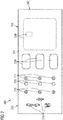
- the cover 200 forms the visible surface of the passenger service unit 10 on the front side of the carrier element 100.
- the cover 200 has, corresponding to the carrier element 100, a first section 201, a second section 202 and a third section 203, which essentially correspond to the dimensions of the corresponding sections 101 to 103 of the carrier element 100 correspond.
- the cover 200 can have a flexible area 204 in which the cover 200 is stretchable.
- the entire cover 200 can be designed to be stretchable.
- At least one electrical and / or electronic element 210 to 216 is integrated in the cover 200.
- lighting means 210 and associated on and off switches 211 can be integrated in the cover 200.
- So-called “smart fabrics” are particularly suitable for this, in which electrically conductive tracks / fibers and / or electrical / electronic components are integrated.
- the latter also include call buttons 215, which can optionally have a light source in order to display a switching state of the call button 215.
- luminous symbols 216 can also be integrated in the cover 200.
- the arrangement of the electrical / electronic elements 210 to 216 as well as other portions of the cover 200 is not limited to the particular arrangement shown.
- the arrangement of the buttons / switches 211 in the examples is shown in FIG Figures 2 and 3 different. That’s what in Figure 3 Optical elements, such as lenses (disks), diffusion disks, or the like to be recognized, which can be arranged in front of corresponding illuminants.
- Openings 220 can be seen in the textile cover 200 for the fresh air supply or loudspeakers, while in FIG Figure 3 there are no such openings.
- the textile cover 200 can be air-permeable (for example perforated) so that a closed textile surface is formed, although fresh air can be supplied to each individual passenger and sound can also be transmitted through the textile cover 200.
- air-permeable for example perforated
- openings must be provided for both the air and the sound.
- a perforation is provided in the cover 200 which defines an opening area 230 for the oxygen mask storage 130.
- This perforation can tear if, for example, a flap or similar closure of the oxygen mask storage 130 opens (in Figure 1 downward).
- the passenger service unit 10 can be produced by slipping the cover 200 over certain sections of the carrier element 100. As in particular in Figure 3 can be seen, a very thin (slim) passenger service unit 10 can be created in a simple manner.
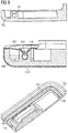
- FIG 4 the back of the cover 200 is shown schematically.
- a pocket 250 is formed at each end of the cover 200. This can be done, for example, by folding over the ends 251 of the cover 200 on its rear side.
- the ends 251 in the side area (in Figure 4 top and bottom) are connected to the main portion 201 of the cover 200. Of course, the entire side areas can be closed. This creates pocket openings across the width of the cover 200, into which the ends (second section 102 and third section 103) of the carrier element 100 can be inserted.
- the cover 200 is thus placed on the carrier element 100 like a sock.
- a contact arrangement 260 having a plurality of contacts 262 may be located on the rear side of the cover 200.
- the contacts 262 are used to connect electrically conductive conductor tracks 263 which are integrated in the coating 200.
- the electrical / electronic elements 210 to 216 can be electrically connected to the contacts 262 of the contact arrangement 260 through the conductor tracks 263.
- the conductor tracks 263 can be integrated in the covering 200 in that they are arranged in its fibers or form parts of the fibers of the covering 200.
- the contact arrangement 260 may further comprise a holding device 261 which, with regard to Figure 16 will be explained in more detail.
- the carrier element 100 can be threaded with one end at one end 203 of the cover 200, and then be threaded at an opposite end 202 of the cover 200.
- the cover 200 spans the carrier element 100.
- the carrier element 100 is inserted in order to hold the cover 200.
- the cover 200 can be held on the carrier element 100 with a silicone cover (not shown separately). It is also possible for the silicone cover to touch the carrier element 100 while the cover 200, for example made of fabric or textile, is arranged (for example glued) on the silicone cover. In this case, the ends 202, 203 of the cover 200 do not have to be pocket-shaped. Instead, a small overlap area is sufficient, as shown in Figure 5 is shown.
- the silicone cover can be stiffer than a thinner cover 200, for example a textile cover, and therefore achieve a greater clamping effect on the carrier element 100.
- a flexible section 204 of the textile cover 200 and / or the silicone cover facilitates the application of the cover 200 to the carrier element 100.
- a further section 205 of the cover 200 can be pushed into an opening between the second section 102 and the first section 101 of the carrier element 100 and clamped there (see FIG Figure 6 ).
- the section of the carrier element 100 shown on the left can also be a carrier element 100 of an adjacently arranged passenger service unit 10, while the cover 200 is stretched over several carrier elements 100 of several passenger service units 10. Any excess material 205 of the coating 200 can be between two carrier elements 100 are inserted and clamped, as shown in FIG Figure 6 can be seen.
- the carrier element 100 can have an inclined section 103 which, as in FIG Figure 6 is aligned with a rear side of the carrier element 100 or, as in FIG Figure 7 shown, is aligned with a front side of the carrier element 100. In both cases, an inclined side is created which can be seen better by a passenger below the passenger service unit 10.
- This inclined section 103 is particularly suitable for the arrangement of symbols 216 which indicate certain information to the passenger, such as a smoking ban, wearing seat belts, prohibiting the use of electronic devices, etc.
- the carrier element 100 can also be designed to be consistently flat, as shown in FIG Figure 8 is shown. This shape is particularly suitable if no parts of the ceiling section of the passenger seat area 2 are to protrude into the latter. As in the Figures 5 to 8 As can be seen, the overlapping areas 250, which form a pocket, can have different thicknesses. It is therefore advisable, in the area of an inclined section 103 of the carrier element 100 ( Figure 7 ) or in the case of a stretchable portion 204 of the cover 200 ( Figure 8 ) to provide a deeper pocket 250 in order to ensure a better hold of the cover 200.
- a fastening device 140 can be provided for fastening the cover 200 to the carrier element 100.
- the carrier element 100 can have a fastening device 140 which is arranged circumferentially at least in sections and which is provided in particular on a rear side of the carrier element 100.
- a simple form of the fastening device 140 can be a barbed section of a Velcro strip, wherein the barbs can hook onto the cover 200.
- FIG Figure 9 A fastening device 140 that is more frequently reusable and more flexible in the longitudinal direction of the carrier element 100 is shown in FIG Figure 9 shown.
- This is designed in the form of a groove on the rear side of the carrier element 100, into which a clamping cord 141 or a similar elongated clamping element can be inserted.
- the clamping cord 141 fits into a part of the groove 140 from which it can only be released by flexible deformation.
- One end of the cover 200 can be pinched between the clamping cord 141 and the groove 140.
- the cross section of the groove 140 can taper towards an opening, so that the clamping cord 141 has an even better hold or the clamping cord 141 is prevented from slipping out.
- the brackets 105 on the rear side of the carrier element 100 are fastened in a vehicle 1 with a corresponding clamping device (not shown).
- the mountings 105 have a similar shape to the clamping cord 141, but are attached to the rear side of the carrier element 100 or integrated therein.
- a clamping device is therefore provided on the vehicle 1, which corresponds to the fastening device 140, so that the clamping device in the vehicle 1 and the holder 105 are inserted into one another and held by means of a clamping effect.
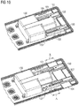
- the second section 102 of the carrier element 100 is shown in more detail.
- the second section 102 rests against the first section 101 of the carrier element 100 (has the smallest distance from the first section 101).
- the second section 102 is shown spaced apart from the first section 101 of the carrier element 100.
- a rail 154 can be provided, which is shown in FIG Figure 11 is shown in detail.
- the rail 154 may be attached to and extend away from the second portion 102.
- the rail 154 can be brought into engagement with a corresponding elongate element 151 so that the rail 154 can only move in the longitudinal direction of the rail 154.
- a locking device 150 can fix a relative position of the second section 102 to the first section 101 of the carrier element 100.
- the illustrated variant of the locking device 150 is provided with openings 152 in the elongated element 151 on the first section 101 in a predetermined grid.
- a corresponding locking element 153 here in the form of a tab, can dip into one of the openings 152, as a result of which movement of the rail 154 relative to the elongate element 151 is blocked.
- the tab 153 can, for example, be pretensioned and automatically move into the opening 152 when it reaches an opening 152. To release the tab 153 must be pulled out of the opening 152, whereby the second section 102 of the carrier element 100 can be moved again.
- the predetermined grid can correspond to a grid with which rows of seats can be arranged in the vehicle 1.
- seat rails have a corresponding grid. If the grids of the seat rail and the openings 152 match, it is possible to increase the seat spacing between two rows of seats also extend the length of the passenger service unit 10 by the same amount. As a result, a service channel in which the passenger service unit 10 is arranged can be closed without additional cover panels.
- Figure 12 shows an alternative embodiment of a rail 154.
- the rail 154 of the second section 102 has a rectangular cross section, which is inserted into a corresponding rectangular holding element 151.
- a screw 155 which clamps the rail 154 in place, can be provided on this holding element 151.
- Figure 12 finally also shows openings 120 in the carrier element 100, in which fresh air nozzles or outlets of fresh air lines and / or loudspeakers can be arranged.
- the second section 102 of the carrier element 100 can also be removed completely, as a result of which one dimension of the carrier element 100 can be shortened. As soon as the rail 154 is no longer in engagement with the elongate (holding) element 151, the second section 102 can be removed.
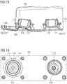
- the Figures 13 and 14 represent details of a pivotable section 111 of the carrier element 100.
- a holding device 110 in the form of a receptacle can be provided on the rear side of the carrier element 100.
- a pivotable section 111 of the carrier element 100 is inserted into the holding device 110, the pivotable section 111 being able to rotate at least partially in the holding device 110.
- the holding device 110 and the pivotable section 111 can have corresponding spherical surfaces.
- the holding device 110 can comprise a magnet (not shown) in order to hold the pivotable section 111 in the holding device 110.
- the holding device 110 can be dimensioned large enough so that the pivotable section 111 cannot slip out.
- the holding device 110 and the pivotable section 111 can be provided at a position of the carrier element 100 which corresponds to or corresponds to a position of one of the at least one electrical and / or electronic element 210 to 216 in the cover 200.
- a part of a Velcro strip 112 comprising a barb is provided on a side of the pivotable section 111 facing the cover 200.
- the barbs of the Velcro tape 112 are designed to hook into the cover 200.
- a part of a Velcro strip (not shown separately) which includes loops and which engages with the barbs 112 can also be provided on the cover 200. This allows the coating 200, as in Figure 13 align by pivoting the pivotable portion 111.
- the electrical / electronic element 210 to 216 provided at this position can therefore also be aligned by the pivotable section 111.
- a light source 210 for example in the form of a flat LED, can be integrated in the cover 200 (as shown in FIG Figure 13 shown) and abut against the pivotable section 111 via the barbs 112. This enables the lighting means (in particular the lighting cone) to be aligned with the aid of the pivotable section 111.
- a lighting means 275 can be arranged in the pivotable section 111.
- the light of the illuminant 275 can exit through an opening 113 in the pivotable section 111. If the cover 200 is now designed to be translucent (transparent and / or perforated and / or by means of an opening) at the position of the pivotable section 111, a pivotable lamp can be implemented in a simple and visually appealing manner.
- a further part of a Velcro strip 115 comprising barb can be arranged around the pivotable section 111 on the carrier element 100. This avoids stresses due to a larger area of the cover 200 when the pivotable section 111 is moved.
- the cover 200 can comprise punched-out portions which form two hook-shaped sections 271, 272. Electrical contact surfaces 273 can be provided at the respective ends of the hook-shaped sections 271, 272. Furthermore, electrical lines (conductor tracks) can be provided in the sections 271, 272 and the adjoining areas of the coating 200. An electrical connection is thereby integrated in the cover 200.
- the electrical contact surfaces 273 can be connected to an electrical / electronic component which is located outside the cover 200.
- a light source 275 as shown in FIG Figure 14 right and in Figure 15 is shown below in a sectional view, with the electrical contact surfaces 273 of the sections 271, 272 are electrically connected (the sections 271, 272 are for better clarity of the Figure 15 only provided with reference symbols for one of the illuminants 275).
- the lighting means 275 can thus comprise a foot 276 which is fastened, for example, in the pivotable section 111 of the carrier element 100 and has corresponding electrical connections to which the contact surfaces 273 can be attached. This variant enables even larger electrical / electronic components to be connected.
- the opening in the cover 200 resulting from the punching can be closed by an optical element 212.
- Figure 16 shows schematically an electrical and / or electronic control 170.
- This can for example be arranged and fastened on the rear side of the carrier element 100.
- the controller 170 can be arranged anywhere on the vehicle.
- the controller 170 can also be at least partially integrated in the cover 200.
- the controller 170 is used to supply the electrical and / or electronic elements 210 to 216 in the cover 200 with electrical current and / or electrical signals.
- the controller 170 has a contact arrangement 160.
- the contact arrangement 160 can be provided with a multiplicity of contacts 162.
- the arrangement of the contacts 162 corresponds to the arrangement of the contacts 262 of the contact arrangement 260 of the coating 200 (see FIG Figure 4 ).
- the contact arrangement 160 also has a holding device 161 which, in its position relative to the contacts 162, corresponds to the holding device 261 on the cover 200, likewise relative to its contacts 262.
- the holding devices 161, 261 can be at least one magnet, so that the two contact arrangements 160, 260 can easily be brought together and firmly connected to one another, with the individual contacts 162, 262 coming to rest on and against one another at the same time, an electrical one Establish connection.
- This form of electrical connection enables a quick connection Installation of the cover 200 and, at the same time, rapid electrical connection via the contact arrangements 160, 260.
- an area for the contact arrangement 160 on the carrier element 100 is shown schematically.
- an opening can be provided in the carrier element 100, through which the contact arrangement 160 extends so that the contact arrangement 260 of the coating 200 can reach and contact it.
- the contact arrangement 160 is integrated into the carrier element 100 and a connection option for connecting the controller 170 is provided on the rear side of the carrier element 100.
- the controller 170 is not arranged and fastened to the carrier element 100, only one connection option needs to be provided for the contact arrangement 160 of the carrier element 100.
- FIG. 3 shows a schematic representation of a vehicle 1, here an aircraft, with a passenger seat area 2. At least one passenger seat 5 and an associated passenger service unit 10 are installed in the passenger seat area 2.
- a plurality of seats / rows of seats 5 can be provided one behind the other in the vehicle 1, with a corresponding plurality of passenger service units 10 being arranged above each seat / row of seats 5. It is sufficient if a corresponding plurality of carrier elements 100 is arranged above each seat / row of seats 5 and a single one cover 200 spans at least two of the plurality of carrier elements 100. As a result, a uniform visual impression can be achieved in the passenger seating area 2. It is also possible to provide a single contact arrangement 260 of one cover 200 (and correspondingly a single contact arrangement 160 in / on the carrier element 100), via which all electrical / electronic elements 210 to 216 can be electrically connected to a controller 170.
- a central controller 7 is also shown by way of example, via which the at least one electrical / electronic element 210 to 216 can be controlled.
- the one cover 200 is electrically connected to the central control 7.
- it can be a cabin management system 7 with which individual or all of the electrical / electronic elements 210 to 216 can be controlled.
- the central controller 7 can be provided in the cabin or, alternatively, in a cockpit of the vehicle 1.
- the central controller 7 can also be connected to a controller 170 in / on the carrier element 100 and / or a controller 170 in the cover 200 and interact with it to control the at least one electrical / electronic element 210 to 216.
Landscapes
- Engineering & Computer Science (AREA)
- Aviation & Aerospace Engineering (AREA)
- Health & Medical Sciences (AREA)
- General Health & Medical Sciences (AREA)
- Pulmonology (AREA)
- Mechanical Engineering (AREA)
- Arrangements Of Lighting Devices For Vehicle Interiors, Mounting And Supporting Thereof, Circuits Therefore (AREA)
Applications Claiming Priority (1)
| Application Number | Priority Date | Filing Date | Title |
|---|---|---|---|
| DE102020104797.5A DE102020104797A1 (de) | 2020-02-24 | 2020-02-24 | Passagierserviceeinheit mit textilem Überzug, Passagiersitzbereich und Fahrzeug mit Passagierserviceeinheit |
Publications (2)
| Publication Number | Publication Date |
|---|---|
| EP3868663A1 true EP3868663A1 (fr) | 2021-08-25 |
| EP3868663B1 EP3868663B1 (fr) | 2023-04-05 |
Family
ID=74666479
Family Applications (1)
| Application Number | Title | Priority Date | Filing Date |
|---|---|---|---|
| EP21157433.0A Active EP3868663B1 (fr) | 2020-02-24 | 2021-02-16 | Unité de service passager dotée d'un element de recouvrement, zone de siège passager et véhicule pourvu d'unité de service passager |
Country Status (4)
| Country | Link |
|---|---|
| US (1) | US11572171B2 (fr) |
| EP (1) | EP3868663B1 (fr) |
| CN (1) | CN113291472A (fr) |
| DE (1) | DE102020104797A1 (fr) |
Families Citing this family (3)
| Publication number | Priority date | Publication date | Assignee | Title |
|---|---|---|---|---|
| US12178927B2 (en) * | 2021-02-02 | 2024-12-31 | B/E Aerospace, Inc. | Gasper knob sanitization |
| USD1034402S1 (en) * | 2021-10-12 | 2024-07-09 | Textron Aviation Inc. | Passenger service unit |
| US12286237B2 (en) * | 2023-02-09 | 2025-04-29 | Goodrich Corporation | Cargo area lighting and monitoring |
Citations (4)
| Publication number | Priority date | Publication date | Assignee | Title |
|---|---|---|---|---|
| EP0716014A1 (fr) * | 1994-12-06 | 1996-06-12 | Drägerwerk Aktiengesellschaft | Couvercle avec réglage longitudinal |
| US20150090839A1 (en) * | 2013-09-30 | 2015-04-02 | Peco Manufacturing Co., Inc. | Passenger Service Unit and Related Systems |
| EP2907751A1 (fr) * | 2014-02-14 | 2015-08-19 | Airbus Operations GmbH | Composant intérieur pour un véhicule doté d'une unité de service passager modulaire |
| EP3546355A1 (fr) | 2018-03-29 | 2019-10-02 | Airbus Operations GmbH | Zone d'aéronef dotée d'un affichage textile, siège de passager d'aéronef doté d'un affichage textile et aéronef comprenant une zone d'aéronef |
Family Cites Families (11)
| Publication number | Priority date | Publication date | Assignee | Title |
|---|---|---|---|---|
| US2569138A (en) * | 1949-11-14 | 1951-09-25 | Howard C Abbott | Electrically heated mattress pad |
| EP1361155B1 (fr) * | 2002-05-10 | 2004-08-25 | Goodrich Hella Aerospace Lighting Systems GmbH | Unité de commande et/ou de visualisation pour véhicules |
| DE102004026835B4 (de) * | 2004-05-28 | 2015-08-27 | E.I.S. Electronics Gmbh | Verbundstoffbauteil und Verfahren zu seiner Herstellung |
| DE102005044719B4 (de) * | 2005-09-19 | 2014-10-30 | B/E Aerospace Systems Gmbh | Verfahren zum Bestücken einer Passagierversorgungseinheit mit Passagiersauerstoffmasken |
| DE102010034410A1 (de) * | 2010-08-14 | 2012-02-16 | Diehl Aerospace Gmbh | Versorgungseinrichtung für eine Passagierkabine |
| DE102011116884B4 (de) * | 2011-10-25 | 2018-07-19 | Airbus Operations Gmbh | Passagierservicemodul und Passagierservicesystem |
| US9205287B2 (en) * | 2013-05-17 | 2015-12-08 | Embraer S.A. | Passenger interface system and assembly thereof |
| US9481462B2 (en) * | 2013-10-04 | 2016-11-01 | Embraer S.A. | Modular passenger service units and assemblies thereof |
| EP3216690B1 (fr) * | 2016-03-07 | 2018-11-07 | Airbus Operations GmbH | Procédé de fabrication d'un tel panneau |
| US10513335B2 (en) * | 2016-10-07 | 2019-12-24 | The Boeing Company | Systems and methods for providing electrical signals to electrical devices within an interior cabin of a vehicle |
| DE102019204355B4 (de) * | 2019-03-28 | 2025-01-09 | Airbus Operations Gmbh | Kameramodul und System zur Überwachung einer Passagierkabine eines Luftfahrzeugs sowie Luftfahrzeug |
-
2020
- 2020-02-24 DE DE102020104797.5A patent/DE102020104797A1/de active Pending
-
2021
- 2021-02-16 EP EP21157433.0A patent/EP3868663B1/fr active Active
- 2021-02-22 US US17/181,591 patent/US11572171B2/en active Active
- 2021-02-22 CN CN202110196891.2A patent/CN113291472A/zh active Pending
Patent Citations (4)
| Publication number | Priority date | Publication date | Assignee | Title |
|---|---|---|---|---|
| EP0716014A1 (fr) * | 1994-12-06 | 1996-06-12 | Drägerwerk Aktiengesellschaft | Couvercle avec réglage longitudinal |
| US20150090839A1 (en) * | 2013-09-30 | 2015-04-02 | Peco Manufacturing Co., Inc. | Passenger Service Unit and Related Systems |
| EP2907751A1 (fr) * | 2014-02-14 | 2015-08-19 | Airbus Operations GmbH | Composant intérieur pour un véhicule doté d'une unité de service passager modulaire |
| EP3546355A1 (fr) | 2018-03-29 | 2019-10-02 | Airbus Operations GmbH | Zone d'aéronef dotée d'un affichage textile, siège de passager d'aéronef doté d'un affichage textile et aéronef comprenant une zone d'aéronef |
Also Published As
| Publication number | Publication date |
|---|---|
| US11572171B2 (en) | 2023-02-07 |
| CN113291472A (zh) | 2021-08-24 |
| US20210261257A1 (en) | 2021-08-26 |
| EP3868663B1 (fr) | 2023-04-05 |
| DE102020104797A1 (de) | 2021-08-26 |
Similar Documents
| Publication | Publication Date | Title |
|---|---|---|
| DE102011005967B4 (de) | Beleuchtungssystem für ein Kraftfahrzeug | |
| EP3868663B1 (fr) | Unité de service passager dotée d'un element de recouvrement, zone de siège passager et véhicule pourvu d'unité de service passager | |
| EP2662241B1 (fr) | Véhicule comprenant un ciel de toit | |
| DE102016110054B4 (de) | Beleuchtungseinrichtung und Interieurteil für ein Fahrzeug | |
| DE202018103669U1 (de) | Beleuchtungsleiter, der innerhalb eines Schiebedachverkleidungsrings integriert ist | |
| DE102016106539A1 (de) | Innenverkleidungsteil eines Kraftfahrzeuges | |
| DE102014006567B4 (de) | Hinterleuchtetes Interieurbauteil | |
| DE102010036795A1 (de) | Verkleidungseinrichtung für ein Kraftfahrzeug mit integriertem Beleuchtungssystem | |
| DE102015013669A1 (de) | Hinterleuchtetes Innenausstattungsteil für ein Kraftfahrzeug | |
| DE202012104088U1 (de) | Formteil | |
| DE102014201730A1 (de) | Innenbauteil für ein fahrzeug | |
| DE112017004685T5 (de) | Fahrzeugsitz mit beleuchteter Komponente | |
| DE102012110153A1 (de) | Formteil und Verfahren zur Herstellung dieses Formteils | |
| EP3847057B1 (fr) | Dispositifs de recouvrement pour recouvrir une zone à l'intérieur d'un véhicule automobile | |
| DE102016219530A1 (de) | Verkleidungsvorrichtung für einen Innenraum eines Kraftfahrzeugs mit Auf- und Durchlichtbeleuchtung | |
| DE102019209519B4 (de) | Schutzvorrichtung für ein Kraftfahrzeug | |
| DE102012009293B4 (de) | Kraftfahrzeug mit Motorhaube und Beleuchtungsanlage | |
| DE102018208740A1 (de) | Verfahren zur Erzeugung einer Innenraumbeleuchtung im Bereich eines Dachausschnitts eines Kraftfahrzeugs sowie Abschattungsanordnung zur Durchführung des Verfahrens | |
| DE102017119618A1 (de) | Luftleitanordnung | |
| DE102017210946A1 (de) | Beleuchtungsanordnung für einen Funktionsraum eines Fahrzeugs | |
| WO2018041479A1 (fr) | Habillage intérieur pour un véhicule à moteur | |
| EP2466573B1 (fr) | Eclairage | |
| DE102011016939B4 (de) | Kraftfahrzeugsitz mit Beleuchtungsvorrichtung | |
| DE102016220072B4 (de) | Innenraumelement für ein Kraftfahrzeug mit einer Textiloberfläche mit einer zur Lichtemission anregbaren Faser | |
| DE102023135770B4 (de) | Kraftfahrzeug mit einem in Längsrichtung und in Querrichtung eines Lichteinlassbereichs verschiebbaren, faltbaren Abdeckelement und Verfahren zum Verdecken eines Lichteinlassbereichs eines Kraftfahrzeugs |
Legal Events
| Date | Code | Title | Description |
|---|---|---|---|
| PUAI | Public reference made under article 153(3) epc to a published international application that has entered the european phase |
Free format text: ORIGINAL CODE: 0009012 |
|
| STAA | Information on the status of an ep patent application or granted ep patent |
Free format text: STATUS: THE APPLICATION HAS BEEN PUBLISHED |
|
| AK | Designated contracting states |
Kind code of ref document: A1 Designated state(s): AL AT BE BG CH CY CZ DE DK EE ES FI FR GB GR HR HU IE IS IT LI LT LU LV MC MK MT NL NO PL PT RO RS SE SI SK SM TR |
|
| STAA | Information on the status of an ep patent application or granted ep patent |
Free format text: STATUS: REQUEST FOR EXAMINATION WAS MADE |
|
| 17P | Request for examination filed |
Effective date: 20211213 |
|
| RBV | Designated contracting states (corrected) |
Designated state(s): AL AT BE BG CH CY CZ DE DK EE ES FI FR GB GR HR HU IE IS IT LI LT LU LV MC MK MT NL NO PL PT RO RS SE SI SK SM TR |
|
| GRAP | Despatch of communication of intention to grant a patent |
Free format text: ORIGINAL CODE: EPIDOSNIGR1 |
|
| STAA | Information on the status of an ep patent application or granted ep patent |
Free format text: STATUS: GRANT OF PATENT IS INTENDED |
|
| RIC1 | Information provided on ipc code assigned before grant |
Ipc: B60Q 3/44 20170101ALI20221014BHEP Ipc: B64D 13/00 20060101ALI20221014BHEP Ipc: B64D 11/00 20060101AFI20221014BHEP |
|
| INTG | Intention to grant announced |
Effective date: 20221114 |
|
| GRAS | Grant fee paid |
Free format text: ORIGINAL CODE: EPIDOSNIGR3 |
|
| GRAA | (expected) grant |
Free format text: ORIGINAL CODE: 0009210 |
|
| STAA | Information on the status of an ep patent application or granted ep patent |
Free format text: STATUS: THE PATENT HAS BEEN GRANTED |
|
| AK | Designated contracting states |
Kind code of ref document: B1 Designated state(s): AL AT BE BG CH CY CZ DE DK EE ES FI FR GB GR HR HU IE IS IT LI LT LU LV MC MK MT NL NO PL PT RO RS SE SI SK SM TR |
|
| REG | Reference to a national code |
Ref country code: GB Ref legal event code: FG4D Free format text: NOT ENGLISH |
|
| REG | Reference to a national code |
Ref country code: CH Ref legal event code: EP |
|
| REG | Reference to a national code |
Ref country code: AT Ref legal event code: REF Ref document number: 1558071 Country of ref document: AT Kind code of ref document: T Effective date: 20230415 |
|
| REG | Reference to a national code |
Ref country code: DE Ref legal event code: R096 Ref document number: 502021000538 Country of ref document: DE |
|
| REG | Reference to a national code |
Ref country code: IE Ref legal event code: FG4D Free format text: LANGUAGE OF EP DOCUMENT: GERMAN |
|
| REG | Reference to a national code |
Ref country code: LT Ref legal event code: MG9D |
|
| REG | Reference to a national code |
Ref country code: NL Ref legal event code: MP Effective date: 20230405 |
|
| PG25 | Lapsed in a contracting state [announced via postgrant information from national office to epo] |
Ref country code: NL Free format text: LAPSE BECAUSE OF FAILURE TO SUBMIT A TRANSLATION OF THE DESCRIPTION OR TO PAY THE FEE WITHIN THE PRESCRIBED TIME-LIMIT Effective date: 20230405 |
|
| PG25 | Lapsed in a contracting state [announced via postgrant information from national office to epo] |
Ref country code: SE Free format text: LAPSE BECAUSE OF FAILURE TO SUBMIT A TRANSLATION OF THE DESCRIPTION OR TO PAY THE FEE WITHIN THE PRESCRIBED TIME-LIMIT Effective date: 20230405 Ref country code: PT Free format text: LAPSE BECAUSE OF FAILURE TO SUBMIT A TRANSLATION OF THE DESCRIPTION OR TO PAY THE FEE WITHIN THE PRESCRIBED TIME-LIMIT Effective date: 20230807 Ref country code: NO Free format text: LAPSE BECAUSE OF FAILURE TO SUBMIT A TRANSLATION OF THE DESCRIPTION OR TO PAY THE FEE WITHIN THE PRESCRIBED TIME-LIMIT Effective date: 20230705 Ref country code: ES Free format text: LAPSE BECAUSE OF FAILURE TO SUBMIT A TRANSLATION OF THE DESCRIPTION OR TO PAY THE FEE WITHIN THE PRESCRIBED TIME-LIMIT Effective date: 20230405 |
|
| PG25 | Lapsed in a contracting state [announced via postgrant information from national office to epo] |
Ref country code: RS Free format text: LAPSE BECAUSE OF FAILURE TO SUBMIT A TRANSLATION OF THE DESCRIPTION OR TO PAY THE FEE WITHIN THE PRESCRIBED TIME-LIMIT Effective date: 20230405 Ref country code: PL Free format text: LAPSE BECAUSE OF FAILURE TO SUBMIT A TRANSLATION OF THE DESCRIPTION OR TO PAY THE FEE WITHIN THE PRESCRIBED TIME-LIMIT Effective date: 20230405 Ref country code: LV Free format text: LAPSE BECAUSE OF FAILURE TO SUBMIT A TRANSLATION OF THE DESCRIPTION OR TO PAY THE FEE WITHIN THE PRESCRIBED TIME-LIMIT Effective date: 20230405 Ref country code: LT Free format text: LAPSE BECAUSE OF FAILURE TO SUBMIT A TRANSLATION OF THE DESCRIPTION OR TO PAY THE FEE WITHIN THE PRESCRIBED TIME-LIMIT Effective date: 20230405 Ref country code: IS Free format text: LAPSE BECAUSE OF FAILURE TO SUBMIT A TRANSLATION OF THE DESCRIPTION OR TO PAY THE FEE WITHIN THE PRESCRIBED TIME-LIMIT Effective date: 20230805 Ref country code: HR Free format text: LAPSE BECAUSE OF FAILURE TO SUBMIT A TRANSLATION OF THE DESCRIPTION OR TO PAY THE FEE WITHIN THE PRESCRIBED TIME-LIMIT Effective date: 20230405 Ref country code: GR Free format text: LAPSE BECAUSE OF FAILURE TO SUBMIT A TRANSLATION OF THE DESCRIPTION OR TO PAY THE FEE WITHIN THE PRESCRIBED TIME-LIMIT Effective date: 20230706 Ref country code: AL Free format text: LAPSE BECAUSE OF FAILURE TO SUBMIT A TRANSLATION OF THE DESCRIPTION OR TO PAY THE FEE WITHIN THE PRESCRIBED TIME-LIMIT Effective date: 20230405 |
|
| PG25 | Lapsed in a contracting state [announced via postgrant information from national office to epo] |
Ref country code: FI Free format text: LAPSE BECAUSE OF FAILURE TO SUBMIT A TRANSLATION OF THE DESCRIPTION OR TO PAY THE FEE WITHIN THE PRESCRIBED TIME-LIMIT Effective date: 20230405 |
|
| REG | Reference to a national code |
Ref country code: DE Ref legal event code: R097 Ref document number: 502021000538 Country of ref document: DE |
|
| PG25 | Lapsed in a contracting state [announced via postgrant information from national office to epo] |
Ref country code: SK Free format text: LAPSE BECAUSE OF FAILURE TO SUBMIT A TRANSLATION OF THE DESCRIPTION OR TO PAY THE FEE WITHIN THE PRESCRIBED TIME-LIMIT Effective date: 20230405 |
|
| PG25 | Lapsed in a contracting state [announced via postgrant information from national office to epo] |
Ref country code: SM Free format text: LAPSE BECAUSE OF FAILURE TO SUBMIT A TRANSLATION OF THE DESCRIPTION OR TO PAY THE FEE WITHIN THE PRESCRIBED TIME-LIMIT Effective date: 20230405 Ref country code: SK Free format text: LAPSE BECAUSE OF FAILURE TO SUBMIT A TRANSLATION OF THE DESCRIPTION OR TO PAY THE FEE WITHIN THE PRESCRIBED TIME-LIMIT Effective date: 20230405 Ref country code: RO Free format text: LAPSE BECAUSE OF FAILURE TO SUBMIT A TRANSLATION OF THE DESCRIPTION OR TO PAY THE FEE WITHIN THE PRESCRIBED TIME-LIMIT Effective date: 20230405 Ref country code: EE Free format text: LAPSE BECAUSE OF FAILURE TO SUBMIT A TRANSLATION OF THE DESCRIPTION OR TO PAY THE FEE WITHIN THE PRESCRIBED TIME-LIMIT Effective date: 20230405 Ref country code: DK Free format text: LAPSE BECAUSE OF FAILURE TO SUBMIT A TRANSLATION OF THE DESCRIPTION OR TO PAY THE FEE WITHIN THE PRESCRIBED TIME-LIMIT Effective date: 20230405 Ref country code: CZ Free format text: LAPSE BECAUSE OF FAILURE TO SUBMIT A TRANSLATION OF THE DESCRIPTION OR TO PAY THE FEE WITHIN THE PRESCRIBED TIME-LIMIT Effective date: 20230405 |
|
| PLBE | No opposition filed within time limit |
Free format text: ORIGINAL CODE: 0009261 |
|
| STAA | Information on the status of an ep patent application or granted ep patent |
Free format text: STATUS: NO OPPOSITION FILED WITHIN TIME LIMIT |
|
| 26N | No opposition filed |
Effective date: 20240108 |
|
| PG25 | Lapsed in a contracting state [announced via postgrant information from national office to epo] |
Ref country code: SI Free format text: LAPSE BECAUSE OF FAILURE TO SUBMIT A TRANSLATION OF THE DESCRIPTION OR TO PAY THE FEE WITHIN THE PRESCRIBED TIME-LIMIT Effective date: 20230405 |
|
| PG25 | Lapsed in a contracting state [announced via postgrant information from national office to epo] |
Ref country code: SI Free format text: LAPSE BECAUSE OF FAILURE TO SUBMIT A TRANSLATION OF THE DESCRIPTION OR TO PAY THE FEE WITHIN THE PRESCRIBED TIME-LIMIT Effective date: 20230405 Ref country code: IT Free format text: LAPSE BECAUSE OF FAILURE TO SUBMIT A TRANSLATION OF THE DESCRIPTION OR TO PAY THE FEE WITHIN THE PRESCRIBED TIME-LIMIT Effective date: 20230405 |
|
| PG25 | Lapsed in a contracting state [announced via postgrant information from national office to epo] |
Ref country code: MC Free format text: LAPSE BECAUSE OF FAILURE TO SUBMIT A TRANSLATION OF THE DESCRIPTION OR TO PAY THE FEE WITHIN THE PRESCRIBED TIME-LIMIT Effective date: 20230405 |
|
| REG | Reference to a national code |
Ref country code: CH Ref legal event code: PL |
|
| PG25 | Lapsed in a contracting state [announced via postgrant information from national office to epo] |
Ref country code: LU Free format text: LAPSE BECAUSE OF NON-PAYMENT OF DUE FEES Effective date: 20240216 |
|
| PG25 | Lapsed in a contracting state [announced via postgrant information from national office to epo] |
Ref country code: CH Free format text: LAPSE BECAUSE OF NON-PAYMENT OF DUE FEES Effective date: 20240229 |
|
| PG25 | Lapsed in a contracting state [announced via postgrant information from national office to epo] |
Ref country code: LU Free format text: LAPSE BECAUSE OF NON-PAYMENT OF DUE FEES Effective date: 20240216 Ref country code: CH Free format text: LAPSE BECAUSE OF NON-PAYMENT OF DUE FEES Effective date: 20240229 |
|
| PG25 | Lapsed in a contracting state [announced via postgrant information from national office to epo] |
Ref country code: BG Free format text: LAPSE BECAUSE OF FAILURE TO SUBMIT A TRANSLATION OF THE DESCRIPTION OR TO PAY THE FEE WITHIN THE PRESCRIBED TIME-LIMIT Effective date: 20230405 |
|
| PG25 | Lapsed in a contracting state [announced via postgrant information from national office to epo] |
Ref country code: BG Free format text: LAPSE BECAUSE OF FAILURE TO SUBMIT A TRANSLATION OF THE DESCRIPTION OR TO PAY THE FEE WITHIN THE PRESCRIBED TIME-LIMIT Effective date: 20230405 |
|
| REG | Reference to a national code |
Ref country code: BE Ref legal event code: MM Effective date: 20240229 |
|
| PG25 | Lapsed in a contracting state [announced via postgrant information from national office to epo] |
Ref country code: BE Free format text: LAPSE BECAUSE OF NON-PAYMENT OF DUE FEES Effective date: 20240229 |
|
| PG25 | Lapsed in a contracting state [announced via postgrant information from national office to epo] |
Ref country code: IE Free format text: LAPSE BECAUSE OF NON-PAYMENT OF DUE FEES Effective date: 20240216 |
|
| PG25 | Lapsed in a contracting state [announced via postgrant information from national office to epo] |
Ref country code: IE Free format text: LAPSE BECAUSE OF NON-PAYMENT OF DUE FEES Effective date: 20240216 Ref country code: BE Free format text: LAPSE BECAUSE OF NON-PAYMENT OF DUE FEES Effective date: 20240229 |
|
| PGFP | Annual fee paid to national office [announced via postgrant information from national office to epo] |
Ref country code: AT Payment date: 20250417 Year of fee payment: 5 |
|
| PG25 | Lapsed in a contracting state [announced via postgrant information from national office to epo] |
Ref country code: CY Free format text: LAPSE BECAUSE OF FAILURE TO SUBMIT A TRANSLATION OF THE DESCRIPTION OR TO PAY THE FEE WITHIN THE PRESCRIBED TIME-LIMIT; INVALID AB INITIO Effective date: 20210216 |
|
| PG25 | Lapsed in a contracting state [announced via postgrant information from national office to epo] |
Ref country code: HU Free format text: LAPSE BECAUSE OF FAILURE TO SUBMIT A TRANSLATION OF THE DESCRIPTION OR TO PAY THE FEE WITHIN THE PRESCRIBED TIME-LIMIT; INVALID AB INITIO Effective date: 20210216 |
|
| PG25 | Lapsed in a contracting state [announced via postgrant information from national office to epo] |
Ref country code: TR Free format text: LAPSE BECAUSE OF FAILURE TO SUBMIT A TRANSLATION OF THE DESCRIPTION OR TO PAY THE FEE WITHIN THE PRESCRIBED TIME-LIMIT Effective date: 20230405 |
|
| PGFP | Annual fee paid to national office [announced via postgrant information from national office to epo] |
Ref country code: GB Payment date: 20260220 Year of fee payment: 6 |
|
| PGFP | Annual fee paid to national office [announced via postgrant information from national office to epo] |
Ref country code: DE Payment date: 20260218 Year of fee payment: 6 |
|
| PGFP | Annual fee paid to national office [announced via postgrant information from national office to epo] |
Ref country code: FR Payment date: 20260218 Year of fee payment: 6 |