EP3868721B1 - Wasserbehandlungssystem - Google Patents
Wasserbehandlungssystem Download PDFInfo
- Publication number
- EP3868721B1 EP3868721B1 EP21168045.9A EP21168045A EP3868721B1 EP 3868721 B1 EP3868721 B1 EP 3868721B1 EP 21168045 A EP21168045 A EP 21168045A EP 3868721 B1 EP3868721 B1 EP 3868721B1
- Authority
- EP
- European Patent Office
- Prior art keywords
- water
- valve
- ozone generator
- valve body
- ozone
- Prior art date
- Legal status (The legal status is an assumption and is not a legal conclusion. Google has not performed a legal analysis and makes no representation as to the accuracy of the status listed.)
- Active
Links
Images







Classifications
-
- C—CHEMISTRY; METALLURGY
- C02—TREATMENT OF WATER, WASTE WATER, SEWAGE, OR SLUDGE
- C02F—TREATMENT OF WATER, WASTE WATER, SEWAGE, OR SLUDGE
- C02F1/00—Treatment of water, waste water, or sewage
- C02F1/72—Treatment of water, waste water, or sewage by oxidation
- C02F1/78—Treatment of water, waste water, or sewage by oxidation with ozone
-
- C—CHEMISTRY; METALLURGY
- C02—TREATMENT OF WATER, WASTE WATER, SEWAGE, OR SLUDGE
- C02F—TREATMENT OF WATER, WASTE WATER, SEWAGE, OR SLUDGE
- C02F1/00—Treatment of water, waste water, or sewage
- C02F1/46—Treatment of water, waste water, or sewage by electrochemical methods
- C02F1/461—Treatment of water, waste water, or sewage by electrochemical methods by electrolysis
- C02F1/467—Treatment of water, waste water, or sewage by electrochemical methods by electrolysis by electrochemical disinfection; by electrooxydation or by electroreduction
- C02F1/4672—Treatment of water, waste water, or sewage by electrochemical methods by electrolysis by electrochemical disinfection; by electrooxydation or by electroreduction by electrooxydation
- C02F1/4674—Treatment of water, waste water, or sewage by electrochemical methods by electrolysis by electrochemical disinfection; by electrooxydation or by electroreduction by electrooxydation with halogen or compound of halogens, e.g. chlorine, bromine
-
- C—CHEMISTRY; METALLURGY
- C02—TREATMENT OF WATER, WASTE WATER, SEWAGE, OR SLUDGE
- C02F—TREATMENT OF WATER, WASTE WATER, SEWAGE, OR SLUDGE
- C02F1/00—Treatment of water, waste water, or sewage
- C02F1/46—Treatment of water, waste water, or sewage by electrochemical methods
- C02F1/461—Treatment of water, waste water, or sewage by electrochemical methods by electrolysis
- C02F1/46104—Devices therefor; Their operating or servicing
- C02F1/46109—Electrodes
- C02F2001/46133—Electrodes characterised by the material
-
- C—CHEMISTRY; METALLURGY
- C02—TREATMENT OF WATER, WASTE WATER, SEWAGE, OR SLUDGE
- C02F—TREATMENT OF WATER, WASTE WATER, SEWAGE, OR SLUDGE
- C02F2103/00—Nature of the water, waste water, sewage or sludge to be treated
- C02F2103/42—Nature of the water, waste water, sewage or sludge to be treated from bathing facilities, e.g. swimming pools
-
- C—CHEMISTRY; METALLURGY
- C02—TREATMENT OF WATER, WASTE WATER, SEWAGE, OR SLUDGE
- C02F—TREATMENT OF WATER, WASTE WATER, SEWAGE, OR SLUDGE
- C02F2201/00—Apparatus for treatment of water, waste water or sewage
- C02F2201/002—Construction details of the apparatus
- C02F2201/004—Seals, connections
-
- C—CHEMISTRY; METALLURGY
- C02—TREATMENT OF WATER, WASTE WATER, SEWAGE, OR SLUDGE
- C02F—TREATMENT OF WATER, WASTE WATER, SEWAGE, OR SLUDGE
- C02F2201/00—Apparatus for treatment of water, waste water or sewage
- C02F2201/002—Construction details of the apparatus
- C02F2201/005—Valves
-
- C—CHEMISTRY; METALLURGY
- C02—TREATMENT OF WATER, WASTE WATER, SEWAGE, OR SLUDGE
- C02F—TREATMENT OF WATER, WASTE WATER, SEWAGE, OR SLUDGE
- C02F2201/00—Apparatus for treatment of water, waste water or sewage
- C02F2201/002—Construction details of the apparatus
- C02F2201/007—Modular design
-
- C—CHEMISTRY; METALLURGY
- C02—TREATMENT OF WATER, WASTE WATER, SEWAGE, OR SLUDGE
- C02F—TREATMENT OF WATER, WASTE WATER, SEWAGE, OR SLUDGE
- C02F2201/00—Apparatus for treatment of water, waste water or sewage
- C02F2201/78—Details relating to ozone treatment devices
- C02F2201/782—Ozone generators
-
- C—CHEMISTRY; METALLURGY
- C02—TREATMENT OF WATER, WASTE WATER, SEWAGE, OR SLUDGE
- C02F—TREATMENT OF WATER, WASTE WATER, SEWAGE, OR SLUDGE
- C02F2201/00—Apparatus for treatment of water, waste water or sewage
- C02F2201/78—Details relating to ozone treatment devices
- C02F2201/784—Diffusers or nozzles for ozonation
-
- C—CHEMISTRY; METALLURGY
- C02—TREATMENT OF WATER, WASTE WATER, SEWAGE, OR SLUDGE
- C02F—TREATMENT OF WATER, WASTE WATER, SEWAGE, OR SLUDGE
- C02F2209/00—Controlling or monitoring parameters in water treatment
- C02F2209/40—Liquid flow rate
Definitions
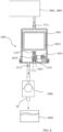
- drain valve assembly 1001′′′ is another drain valve design in accordance with the claimed invention.
- Valve 1001′′′ is similar in structure and function to valves 1001, 1001' and 1001" described above, and corresponding references numbers indicate corresponding structures among valves 1001, 1001', 1001", 1001'".
- valve 1001′′′ also includes a hollow valve body 1011 and a float 1012 disposed in the valve body 1011.
- the valve body 1011 has an inlet 1111 and an outlet 1112 therethrough. At the bottom, there is a drain outlet 1113.
- the bottom of the float 1012 is provided with a boss 1122 having a gasket 1013 mounted thereto, and the gasket 1013 can selectively seal the drain outlet 1113.
- the outer periphery of float 1012 includes a plurality of ribs 1123, shown in Fig. 12 , which operate to center the float 1012 within valve body 1011 while introducing minimal friction between float 1012 and valve body 1011.
- the gaps between the non-ribbed portions of float 1012 and the inner wall of the valve body 1011 allow free flow of gas and water during operation of the drain valve assembly 1001, 1001', 1001" or 1001′′′.
- a combination ozone/sodium hypochlorite treatment assembly 2001 compatible with water treatment system 10 includes a tube-shaped tank having a fluid inlet 2002 and a fluid outlet 2003 which can be respectively connected to base 1 of water treatment system 10 as shown in Figs. 1 and 2 .
- a first flow passageway 2011 communicates with fluid inlet 2002, and fluid outlet 2003 via an intermediate mixing chamber 2015 while a separate second flow passageway 2012 communicates fluid inlet 2002 and fluid outlet 2003 via mixing chamber 2015.
- the first flow passageway 2011 has an electrolytic chlorine generator with electrode plates 2004, specifically titanium electrode plates 2004.
- the second passageway 2012 includes a constriction 2012A followed by a downstream opening 2012B to define a venturi structure.
- the second flow passageway 2012 further incudes an ozone inlet 2013 ( Fig. 15 ) to which the ozone generator 3 of water treatment system 10 can be connected in order to feed ozone into combination treatment assembly 2001 as further described below.
- the water that flows into first flow passageway 2011 comes into contact with titanium plate 2004 of the electrolytic chlorine generator, which electrolyzes salt in the water to produce sodium hypochlorite to sanitize the water flow.
- This generated sodium hypochlorite continues with the sanitized flow of the water to the fluid outlet 2003 of combination treatment assembly 2001 and is returned to the pool.
- the water that flows into second flow passageway 2012 encounters the venturi structure 2012A, 2012B therein, such that a vacuum effect is generated at the ozone inlet 2013.
- This vacuum draws the ozone generated by the ozone generator 3 of water treatment system 10 into the water flow through passageway 2012 via the ozone inlet 2013.
- the ozone mixes with the water flow in mixing chamber 2015 ( Fig.
- This sanitized water flows to the fluid outlet 2003 of combination treatment assembly 2001 and is returned to the pool.
- the sodium hypochlorite-containing water stream and the ozone-containing water stream are also mixed with one another at the fluid outlet 2003, so that the combined sanitized water flows return to the pool together to sterilize the pool water.
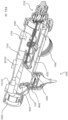
- Combination treatment assembly 3001 provides a flow regulator or restrictor 3007 to ensure that the combination treatment assembly 3001 is capable of effectively drawing ozone and/or disinfectant to ensure the quality of the pool water disinfection, as described in detail below.
- Combination treatment assembly 3001 is substantially similar to combination treatment assembly 2001 described in detail above, with reference numerals of combination treatment assembly 3001 analogous to the reference numerals used in combination treatment assembly 2001, except with 1000 added thereto. Elements of combination treatment assembly 3001 correspond to similar elements denoted by corresponding reference numerals of combination treatment assembly 2001, except as otherwise noted.
- valve 3007 includes a valve body 3071 with base 3072 at an outlet end thereof, with a fluid outlet 3721 formed between the base 3072 and the valve body 3071.
- a limit block 3073 is connected to the opposing inlet end of valve body 3071, and cooperates with a valve 3074.
- the valve 3074 is disposed within valve body 3071 to selectively permit or restrict flow through regulating valve 3007 as further described below.
- valve body 3071 has an elliptical shape to generally conform to the shape of flow passageway 3011, while valve end cap 3742 and the associated valve seat 3731 are round as illustrated.
- valve 3074 includes a longitudinal connecting portion 3741 having an arched, rounded end cap 3742 disposed at the upstream end thereof.
- the inner diameter of the limit block 3073 is smaller than that of the valve body 3071, with a valve seat 3731 formed as a stepped-down portion of block 3073 and configured to interact with end cap 3742 of valve body 3071 to regulate fluid flow through valve 3007.
- the end cap 3742 is biased toward the valve seat 3731 to form a restricted valve configuration as seen in Fig. 19 .
- valve 3074 of the flow regulating valve 3007 is subjected to a downstream-directed force by the impact of the incoming flow, and this force is proportional to the water pressure provided by the upstream water pump. This force acts to compress spring 3075, thereby opening valve 3074 to the high-flow configuration shown in Fig. 20 . This allows an increased flow through the first fluid passageway 3011, and the remainder of the incoming flow passes through the second fluid passageway 3012.
- valve 3074 is subjected to a relatively small impact force from the incoming water flow.
- Spring 3075 will maintain valve 3074 nearer to a restricted-flow configuration as shown in Fig. 19 , thereby ensuring that a larger proportion of the incoming flow is delivered to the second fluid passageway 3012 as compared to the Fig. 20 configuration described above.
- combination treatment assembly 3001 includes a flow rate monitoring switch 3005 disposed in first fluid passageway 3011 as shown in Figs. 17 and 18 .
- This flow rate monitoring switch 3005 may be connected to ozone generator 3 and/or the electrolytic chlorine generator (e.g. electrode 3004) such that a flow in first fluid passageway 3011 that is unable to pivot flapper 3006 upwardly toward switch 3008 will deactivate the corresponding component.
- Monitoring switch 3005 may act to protect electrode 3004 in the same manner discussed above with respect to monitoring switch 2005 and titanium plate 2004.
- using switch 3005 to deactivate ozone generator 3 may ensure that ozone is not presented to suction inlet 3013 ( Fig. 16 ) except when a vacuum effect can be produced in venturi structure 3012A, 3012B by adequate flow through the second passageway 3012. If the fluid flow is does not meet a predetermined threshold for production of an adequate venturi effect, the upstream electrolytic chlorine generator and/or ozone generator 3 may be deactivated unless and until such predetermined threshold is met.
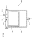
- electrolytic chlorine generator 4010 having a body 4001 with insulated electrode plate assembly 4002 contained therein.
- insulated electrode plate assembly 4002 includes one or more electrode plates 4021 (illustratively, three plates 4021 as best seen in Fig. 27 ) located in the body 4001 and mounted to an insulating base 4022 fixed to body 4001. Where multiple electrode plates 4021 are employed as shown, the plates 4021 are arranged and fixed side by side on the insulating base 4022. One of the two adjacent electrode plates 4021 is close to the side edge of the other electrode plate 4021 and contacts an insulating assembly 4023 ( Fig. 23 ) protruding out from the side edge of the other electrode plate 4021. Insulating assembly 4023 is, in turn, connected to the insulating base 4022.
- This arrangement poses a barrier to the formation of an electrical connection between the edges of two adjacent electrode plates 4021 through the insulating assembly 4023, such that current leakage can be avoided at the edges of the adjacent electrode plates 4021. Reduced current leakage results in a concomitantly reduced loss of electrolysis and thus increased electrolysis efficiency.
- body 4001 is formed by the combination of a generally bucket-shaped portion A and having a lid B fitted to the open upper end thereof.
- a vent aperture 4011 is provided for discharging hydrogen via the top of tank body 4001.
- One or more fluid inlets 4012 allow for fluid (e.g., salt water) inflow and fluid outlet 4013 allows for discharging sodium hypochlorite solution at the bottom of body 4001.
- two fluid inlets 4012 are provided, which allows for the inflow of saturated salt water and fresh water respectively.
- the salt concentration of the fluid contained inside body 4001 can be controlled, thus the solubility of the sodium hypochlorite solution produced by electrolysis can also be controlled.
- two float switches 4015 corresponding to two different water levels may be provided in body 4001 in order to facilitate the control over the respective fluid flows to each fluid inlet 4012.
- a mounting hole 4014 is formed in the side wall of body 4001 which is sized to receive the insulating base 4022.
- Base 4022 can be fixed in the mounting hole 4014 together with plates 4021 and insulating assembly 4023, as illustrated.
- Insulating base 4022 further includes a terminal post 4221 electrically connected to each electrode plate 4021 to supply power to the electrode plate 4021.
- electrode plates 4021 are made of titanium, similar to plates 2004 and 3004 described in detail above, to prevent corrosion and facilitate electrolysis.
- plates 2004 and 3004 described above may be formed using the same principles of insulation and modular mounting described herein with respect to electrolytic chlorine generator 4010.
- insulating assembly 4023 includes an insulating frame 4231, at least one upper insulating separator 4232 and at least one lower insulating separator 4233 ( Fig. 27 ).
- Insulating frame 4231 is fixed to the insulating base 4022.
- a plurality of slots, best shown in Fig. 27 are provided at the inner surfaces of the front and back walls of frame 4231. These slots allow electrode plates 4021 to be vertically inserted (i.e., along a top-to-bottom direction from the perspective of Figs. 25 and 27 ) into the insulating frame 4231, such that the each plate 4021 is held at a distance from the adjacent plate(s) 4231.
- the upper and lower edges of adjacent electrode plates 4021 are further electrically isolated by upper insulating separator 4232 and a lower insulating separator 4233, respectively.
- the front and back ends of upper insulating separators 4232 are respectively connected to the front and back walls of the upper portion of insulating frame 4231, such that the upper edges of upper insulating separators 4232 upwardly protrude away from the upper edge of the adjacent electrode plate 4021.
- the front and back ends of lower insulating separator 4233 are respectively connected to the front and back walls of at the lower portion of insulating frame 4231, such that the lower edge of lower insulating separator 4233 protrudes downwardly away from the lower edge of the adjacent electrode plate 4021.
- adjacent edges of electrode plates 4021 can be physically close one another, but shielded from one another by the insulating assembly 4023 via insulating frame 4231, upper insulating separator 4232 and lower insulating separator 4233.
- three electrode plates 4021 are included in electrolytic chlorine generator 4010, and fixed in position relative to one another by insulating frame 4231.
- the left and right sides of the three electrode plates 4021 are mutually opposite to, and facing each other.
- the left plate 4021 may be the first anode plate
- the middle plate 4021 may be the cathode plate
- right plate 4021 may be the second anode plate.
- the upper insulating separators 4232 and the lower insulating separator 4233 may be arranged such that the upper and lower edges of the right side of the (left-most) first anode plate 4021 are respectively in contact with the left pair of upper and lower insulating separators 4232 and 4233.
- the upper and lower edges of the right side of the (middle) cathode plate 4021 are respectively in contact with the right pair of upper and lower insulating separators 4232 and 4233.
- the (right-most) second anode plate 4021 need not be in direct contact with any of the upper and lower insulating separators 4232 and 4233. This arrangement provides effective electrical insulation between the respective plates 4021.
- the respective left sides of the (middle) cathode plate 4021 and the (right-most) second anode plate 4021 may be contacted at their upper and lower edges by respective pairs of upper and lower insulating separators 4232 and 4233.
- the (left-most) first anode plate 4021 need not be in direct contact with any of the upper and lower insulating separators 4232 and 4233. This alternative arrangement will also product effective electrical insulation between the respective plates 4021.
- electrolytic chlorine generator 4010 allows for efficient generation of sodium hypochlorite by mitigating or eliminating current leakage among the electrode plates 4021. In the absence of such current leakage, the efficiency of the electrolysis process is improved such that sodium hypochlorite may be produced with a minimal power input.
Landscapes
- Chemical & Material Sciences (AREA)
- Life Sciences & Earth Sciences (AREA)
- Hydrology & Water Resources (AREA)
- Engineering & Computer Science (AREA)
- Environmental & Geological Engineering (AREA)
- Water Supply & Treatment (AREA)
- Organic Chemistry (AREA)
- Chemical Kinetics & Catalysis (AREA)
- Electrochemistry (AREA)
- General Chemical & Material Sciences (AREA)
- Treatment Of Water By Oxidation Or Reduction (AREA)
- Electrolytic Production Of Non-Metals, Compounds, Apparatuses Therefor (AREA)
Claims (6)
- Wasserbehandlungssystem (10), das zur Verwendung mit einem Becken (1003) konfiguriert ist, wobei das Wasserbehandlungssystem (10) umfasst:einen Fluiddurchgang in Fluidverbindung mit dem Becken;einen Ozongenerator (3), der zum Zuführen von Ozongas zu dem Fluiddurchgang konfiguriert ist; undeine Ablassventilanordnung (1001), die stromabwärts des Ozongenerators (3) und stromaufwärts des Beckens (1003) positioniert ist, wobei die Ablassventilanordnung (1001) umfasst:einen Ventilkörper mit einem Einlass, einem Auslass und einem Ablassauslass; undein im Ventilkörper angeordnetes Schwimmerventil, wobei das Schwimmerventil den Ablassauslass (1113) schließt, wenn Wasser vom Ozongenerator (3) in den Einlass des Ventilkörpers eintritt, und nach oben schwimmt, um den Ablassauslass (1113) zu öffnen, wenn Wasser vom Becken (1003) in den Auslass des Ventilkörpers eintritt.
- Wasserbehandlungssystem (10) nach Anspruch 1, wobei die Ablassventilanordnung (1001) ferner eine Feder (1016) umfasst, die das Schwimmerventil zum Ablassauslass (1113) des Ventilkörpers (1011) hin vorspannt.
- Wasserbehandlungssystem (10) nach Anspruch 1, wobei:der Einlass (1111) an einer Oberseite des Ventilkörpers (1011) positioniert ist; undder Auslass (1112) und der Ablassauslass (1113) an einer Unterseite des Ventilkörpers (1011) positioniert sind.
- Wasserbehandlungssystem (10) nach Anspruch 1, wobei:der Einlass (1111) und der Auslass (1112) an einer Oberseite des Ventilkörpers (1011) positioniert sind; undder Ablassauslass (1113) an einer Unterseite des Ventilkörpers (1011) positioniert ist.
- Wasserbehandlungssystem (10) nach Anspruch 1, wobei das Schwimmerventil umfasst:einen Schwimmer (1012);eine Verbindungsstange (1014), die schwenkbar mit dem Ventilkörper (1011) gekoppelt ist und zur Bewegung mit dem Schwimmer (1012) konfiguriert ist; undein Dichtungselement (1013), das mit der Verbindungsstange (1014) gekoppelt ist.
- Wasserbehandlungssystem (10) nach Anspruch 1, wobei das Schwimmerventil umfasst:einen Schwimmer (1012), der einen von einer Unterseite des Schwimmers (1012) vorstehenden Vorsprung (1122) aufweist; undein Dichtungselement (1013), das mit dem Vorsprung (1122) gekoppelt ist.
Applications Claiming Priority (7)
| Application Number | Priority Date | Filing Date | Title |
|---|---|---|---|
| CN201720341531.6U CN206708513U (zh) | 2017-04-01 | 2017-04-01 | 臭氧发生器的保护排水阀 |
| CN201720344145.2U CN206828097U (zh) | 2017-04-01 | 2017-04-01 | 臭氧发生器模块更换结构 |
| CN201720341325.5U CN206814465U (zh) | 2017-04-01 | 2017-04-01 | 臭氧加氯电解槽组结构 |
| CN201721500831.0U CN207525345U (zh) | 2017-11-10 | 2017-11-10 | 一种次氯酸钠发生器用箱式电解槽 |
| CN201721531399.1U CN207525022U (zh) | 2017-11-16 | 2017-11-16 | 具有流量调节功能的电解槽 |
| EP18777988.9A EP3606879A4 (de) | 2017-04-01 | 2018-03-31 | Wasserbehandlungssystem |
| PCT/IB2018/052242 WO2018178952A1 (en) | 2017-04-01 | 2018-03-31 | Water treatment system |
Related Parent Applications (1)
| Application Number | Title | Priority Date | Filing Date |
|---|---|---|---|
| EP18777988.9A Division EP3606879A4 (de) | 2017-04-01 | 2018-03-31 | Wasserbehandlungssystem |
Publications (2)
| Publication Number | Publication Date |
|---|---|
| EP3868721A1 EP3868721A1 (de) | 2021-08-25 |
| EP3868721B1 true EP3868721B1 (de) | 2025-03-12 |
Family
ID=63677382
Family Applications (4)
| Application Number | Title | Priority Date | Filing Date |
|---|---|---|---|
| EP21168045.9A Active EP3868721B1 (de) | 2017-04-01 | 2018-03-31 | Wasserbehandlungssystem |
| EP21168042.6A Active EP3868720B1 (de) | 2017-04-01 | 2018-03-31 | Wasserbehandlungssystem |
| EP18777988.9A Withdrawn EP3606879A4 (de) | 2017-04-01 | 2018-03-31 | Wasserbehandlungssystem |
| EP25159194.7A Pending EP4567004A3 (de) | 2017-04-01 | 2018-03-31 | Wasserbehandlungssystem |
Family Applications After (3)
| Application Number | Title | Priority Date | Filing Date |
|---|---|---|---|
| EP21168042.6A Active EP3868720B1 (de) | 2017-04-01 | 2018-03-31 | Wasserbehandlungssystem |
| EP18777988.9A Withdrawn EP3606879A4 (de) | 2017-04-01 | 2018-03-31 | Wasserbehandlungssystem |
| EP25159194.7A Pending EP4567004A3 (de) | 2017-04-01 | 2018-03-31 | Wasserbehandlungssystem |
Country Status (3)
| Country | Link |
|---|---|
| US (3) | US11274052B2 (de) |
| EP (4) | EP3868721B1 (de) |
| WO (1) | WO2018178952A1 (de) |
Families Citing this family (5)
| Publication number | Priority date | Publication date | Assignee | Title |
|---|---|---|---|---|
| US11274052B2 (en) | 2017-04-01 | 2022-03-15 | Intex Marketing Ltd. | Water treatment system |
| GB2580452B (en) * | 2018-12-27 | 2021-06-09 | Humigal Ltd | Membrane assemblies with sealing fault detection and location, and related methods |
| CN114110215A (zh) * | 2021-11-17 | 2022-03-01 | 浙江金大万翔环保技术有限公司 | 一种自动止回排水阀 |
| EP4463424A4 (de) * | 2022-01-10 | 2026-01-14 | Maytronics Australia Pty Ltd | Venturi-design und system damit zur dosierverwendung bei der wasserbehandlung |
| CN115491705B (zh) * | 2022-10-14 | 2024-08-16 | 深圳康诚博信科技有限公司 | 一种臭氧发生装置的气水分离单元 |
Family Cites Families (31)
| Publication number | Priority date | Publication date | Assignee | Title |
|---|---|---|---|---|
| US4100052A (en) * | 1976-11-11 | 1978-07-11 | Diamond Shamrock Corporation | Electrolytic generation of halogen biocides |
| US4790923A (en) * | 1987-07-07 | 1988-12-13 | Stillman Neil W | Liquid treating electrolytic cell |
| AUPM498394A0 (en) | 1994-04-12 | 1994-05-05 | Berrett Pty Ltd | Electrolytic water treatment |
| JP3318186B2 (ja) | 1995-05-19 | 2002-08-26 | 科学技術振興事業団 | ガスクラスターの形成方法と薄膜形成方法 |
| US7329343B1 (en) * | 1999-09-10 | 2008-02-12 | Barnes Ronald L | Water treatment bypass loops having ozone and chlorine generators |
| US6551518B2 (en) * | 1999-07-12 | 2003-04-22 | Joseph Gargas | Combined ozonation and electrolytic chlorination water purification method |
| US6277288B1 (en) * | 1999-07-12 | 2001-08-21 | Joseph Gargas | Combined ozonation and electrolytic chlorination water purification method |
| JP4020787B2 (ja) | 2001-04-27 | 2007-12-12 | 三洋電機株式会社 | 水処理装置 |
| US6761827B2 (en) | 2001-10-26 | 2004-07-13 | Zodiac Pool Care, Inc. | Method and apparatus for purifying water |
| US20060027463A1 (en) * | 2004-06-23 | 2006-02-09 | Del Industries, Inc. | Water treatment apparatus utilizing ozonation and electrolytic chlorination |
| US7879208B2 (en) | 2006-02-03 | 2011-02-01 | Zodiac Pool Systems, Inc. | Multi-port chlorine generator |
| EP2039807B1 (de) | 2006-07-07 | 2019-05-15 | Kinotech Solar Energy Corporation | Elektrolysesystem und -verfahren |
| CN201121150Y (zh) | 2007-10-29 | 2008-09-24 | 什洛莫·塔米尔 | 水处理系统 |
| US8266736B2 (en) | 2009-07-16 | 2012-09-18 | Watkins Manufacturing Corporation | Drop-in chlorinator for portable spas |
| CN101993135B (zh) | 2009-08-28 | 2012-05-09 | 明达实业(厦门)有限公司 | 用于游泳池的2合1氯铜/溴铜消毒器 |
| US8277621B2 (en) | 2009-08-31 | 2012-10-02 | Time Asia International Creation Limited | Halogen generator for above ground pools |
| CN201818845U (zh) | 2010-02-04 | 2011-05-04 | 唐平安 | 一种臭氧气体单向阀装置 |
| ES2373601B1 (es) | 2011-10-14 | 2013-02-08 | I.D. Electroquímica, S.L. | Procedimiento de depuración de agua sin aporte de sales y reactor de depuración de agua. |
| CN103964586B (zh) | 2014-05-22 | 2016-01-13 | 宁波市可汉电器有限公司 | 一种水处理器 |
| TWI684678B (zh) * | 2014-09-08 | 2020-02-11 | 日商大幸藥品股份有限公司 | 電解式二氧化氯氣體製造裝置 |
| CN104326608B (zh) | 2014-11-19 | 2016-09-07 | 中国船舶重工集团公司第七二五研究所 | 一种多级电化学污水处理方法及装置 |
| US20180297862A1 (en) * | 2015-05-19 | 2018-10-18 | Formarum Inc. | Water treatment system and method |
| US20170036926A1 (en) | 2015-08-06 | 2017-02-09 | Ryland Wilson | Water Sanitizing System |
| CN106995229B (zh) | 2016-01-22 | 2021-04-16 | 南京理工大学 | 一种双管式膜电极电催化反应器 |
| CN207525022U (zh) | 2017-11-16 | 2018-06-22 | 明达实业(厦门)有限公司 | 具有流量调节功能的电解槽 |
| CN206708513U (zh) * | 2017-04-01 | 2017-12-05 | 明达实业(厦门)有限公司 | 臭氧发生器的保护排水阀 |
| CN206828097U (zh) * | 2017-04-01 | 2018-01-02 | 明达实业(厦门)有限公司 | 臭氧发生器模块更换结构 |
| US11274052B2 (en) | 2017-04-01 | 2022-03-15 | Intex Marketing Ltd. | Water treatment system |
| CN206814465U (zh) * | 2017-04-01 | 2017-12-29 | 明达实业(厦门)有限公司 | 臭氧加氯电解槽组结构 |
| CN208440333U (zh) | 2018-03-27 | 2019-01-29 | 深圳安吉尔饮水产业集团有限公司 | 自由基发生装置及净水设备 |
| CN209974383U (zh) | 2019-04-17 | 2020-01-21 | 明达实业(厦门)有限公司 | 泳池水处理设备的水流监测结构 |
-
2018
- 2018-03-31 US US16/498,919 patent/US11274052B2/en active Active
- 2018-03-31 WO PCT/IB2018/052242 patent/WO2018178952A1/en not_active Ceased
- 2018-03-31 EP EP21168045.9A patent/EP3868721B1/de active Active
- 2018-03-31 EP EP21168042.6A patent/EP3868720B1/de active Active
- 2018-03-31 EP EP18777988.9A patent/EP3606879A4/de not_active Withdrawn
- 2018-03-31 EP EP25159194.7A patent/EP4567004A3/de active Pending
-
2021
- 2021-08-31 US US17/463,064 patent/US11807560B2/en active Active
- 2021-08-31 US US17/463,081 patent/US11795078B2/en active Active
Also Published As
| Publication number | Publication date |
|---|---|
| US11795078B2 (en) | 2023-10-24 |
| US20210395119A1 (en) | 2021-12-23 |
| EP4567004A3 (de) | 2025-10-08 |
| EP3868720B1 (de) | 2025-04-02 |
| EP3868721A1 (de) | 2021-08-25 |
| EP3606879A1 (de) | 2020-02-12 |
| EP4567004A2 (de) | 2025-06-11 |
| US11807560B2 (en) | 2023-11-07 |
| EP3868720A1 (de) | 2021-08-25 |
| US20210087085A1 (en) | 2021-03-25 |
| EP3606879A4 (de) | 2021-01-06 |
| WO2018178952A1 (en) | 2018-10-04 |
| US11274052B2 (en) | 2022-03-15 |
| US20210395118A1 (en) | 2021-12-23 |
Similar Documents
| Publication | Publication Date | Title |
|---|---|---|
| US11807560B2 (en) | Water treatment system | |
| CN101823781B (zh) | 用于生产无菌水的单元、包括所述单元的筒以及包括所述筒的洗衣机 | |
| US4229272A (en) | Chlorine generator and method | |
| AU595145B2 (en) | Electrolytic pool chlorinator | |
| US11045829B2 (en) | Self-sealing shower head with disinfectant | |
| CN213570771U (zh) | 一种消毒液制造机 | |
| US4250126A (en) | Chlorine generator and method | |
| KR100531667B1 (ko) | 저수조를 자동으로 살균할 수있는 정수기 및 그 정수기의살균방법 | |
| CN113181392B (zh) | 具有消毒功能的工作站 | |
| CN112137552B (zh) | 一种电解消毒模块及洗碗机 | |
| KR102716927B1 (ko) | 수처리장치 | |
| TW202340537A (zh) | 具有自我消毒功能的氫氣產生器 | |
| TWI868521B (zh) | 具有洩壓功能的氫氣產生裝置 | |
| US11872173B2 (en) | Nursing machine host and nursing machine to which same belongs | |
| CN215479921U (zh) | 水处理设备 | |
| EP3808709B1 (de) | Wasserdesinfektion durch elektrolyse | |
| JP6694580B2 (ja) | 水栓装置 | |
| CN217377400U (zh) | 一种电解水消毒装置 | |
| KR20230034777A (ko) | 직접냉각과 간접냉각이 결합된 차염생성전해조 | |
| CN121853323A (zh) | 除菌液发生装置、洗涤剂投放系统和洗涤设备 | |
| KR20130117598A (ko) | 수처리장치 | |
| KR20100110462A (ko) | 인체 소독기 | |
| KR20120133703A (ko) | 살균기능을 가진 수처리기기 | |
| KR20240081814A (ko) | 미세기포 및 전기분해 결합형 양식장 수질개선장치 | |
| WO2017057449A1 (ja) | 除菌水生成装置及びこれを備える便器装置 |
Legal Events
| Date | Code | Title | Description |
|---|---|---|---|
| PUAI | Public reference made under article 153(3) epc to a published international application that has entered the european phase |
Free format text: ORIGINAL CODE: 0009012 |
|
| STAA | Information on the status of an ep patent application or granted ep patent |
Free format text: STATUS: THE APPLICATION HAS BEEN PUBLISHED |
|
| AC | Divisional application: reference to earlier application |
Ref document number: 3606879 Country of ref document: EP Kind code of ref document: P |
|
| AK | Designated contracting states |
Kind code of ref document: A1 Designated state(s): AL AT BE BG CH CY CZ DE DK EE ES FI FR GB GR HR HU IE IS IT LI LT LU LV MC MK MT NL NO PL PT RO RS SE SI SK SM TR |
|
| STAA | Information on the status of an ep patent application or granted ep patent |
Free format text: STATUS: REQUEST FOR EXAMINATION WAS MADE |
|
| 17P | Request for examination filed |
Effective date: 20220225 |
|
| RBV | Designated contracting states (corrected) |
Designated state(s): AL AT BE BG CH CY CZ DE DK EE ES FI FR GB GR HR HU IE IS IT LI LT LU LV MC MK MT NL NO PL PT RO RS SE SI SK SM TR |
|
| GRAP | Despatch of communication of intention to grant a patent |
Free format text: ORIGINAL CODE: EPIDOSNIGR1 |
|
| STAA | Information on the status of an ep patent application or granted ep patent |
Free format text: STATUS: GRANT OF PATENT IS INTENDED |
|
| RIC1 | Information provided on ipc code assigned before grant |
Ipc: C02F 103/42 20060101ALN20240515BHEP Ipc: C02F 1/461 20060101ALI20240515BHEP Ipc: C02F 1/467 20060101ALI20240515BHEP Ipc: C02F 1/78 20060101AFI20240515BHEP |
|
| INTG | Intention to grant announced |
Effective date: 20240606 |
|
| GRAJ | Information related to disapproval of communication of intention to grant by the applicant or resumption of examination proceedings by the epo deleted |
Free format text: ORIGINAL CODE: EPIDOSDIGR1 |
|
| STAA | Information on the status of an ep patent application or granted ep patent |
Free format text: STATUS: REQUEST FOR EXAMINATION WAS MADE |
|
| GRAP | Despatch of communication of intention to grant a patent |
Free format text: ORIGINAL CODE: EPIDOSNIGR1 |
|
| STAA | Information on the status of an ep patent application or granted ep patent |
Free format text: STATUS: GRANT OF PATENT IS INTENDED |
|
| INTG | Intention to grant announced |
Effective date: 20241014 |
|
| RIC1 | Information provided on ipc code assigned before grant |
Ipc: C02F 103/42 20060101ALN20241007BHEP Ipc: C02F 1/461 20060101ALI20241007BHEP Ipc: C02F 1/467 20060101ALI20241007BHEP Ipc: C02F 1/78 20060101AFI20241007BHEP |
|
| P01 | Opt-out of the competence of the unified patent court (upc) registered |
Free format text: CASE NUMBER: APP_63655/2024 Effective date: 20241129 |
|
| GRAS | Grant fee paid |
Free format text: ORIGINAL CODE: EPIDOSNIGR3 |
|
| GRAA | (expected) grant |
Free format text: ORIGINAL CODE: 0009210 |
|
| STAA | Information on the status of an ep patent application or granted ep patent |
Free format text: STATUS: THE PATENT HAS BEEN GRANTED |
|
| AC | Divisional application: reference to earlier application |
Ref document number: 3606879 Country of ref document: EP Kind code of ref document: P |
|
| AK | Designated contracting states |
Kind code of ref document: B1 Designated state(s): AL AT BE BG CH CY CZ DE DK EE ES FI FR GB GR HR HU IE IS IT LI LT LU LV MC MK MT NL NO PL PT RO RS SE SI SK SM TR |
|
| REG | Reference to a national code |
Ref country code: GB Ref legal event code: FG4D |
|
| REG | Reference to a national code |
Ref country code: CH Ref legal event code: EP |
|
| REG | Reference to a national code |
Ref country code: DE Ref legal event code: R096 Ref document number: 602018080184 Country of ref document: DE |
|
| REG | Reference to a national code |
Ref country code: IE Ref legal event code: FG4D |
|
| REG | Reference to a national code |
Ref country code: NL Ref legal event code: FP |
|
| PG25 | Lapsed in a contracting state [announced via postgrant information from national office to epo] |
Ref country code: RS Free format text: LAPSE BECAUSE OF FAILURE TO SUBMIT A TRANSLATION OF THE DESCRIPTION OR TO PAY THE FEE WITHIN THE PRESCRIBED TIME-LIMIT Effective date: 20250612 |
|
| PG25 | Lapsed in a contracting state [announced via postgrant information from national office to epo] |
Ref country code: FI Free format text: LAPSE BECAUSE OF FAILURE TO SUBMIT A TRANSLATION OF THE DESCRIPTION OR TO PAY THE FEE WITHIN THE PRESCRIBED TIME-LIMIT Effective date: 20250312 |
|
| PG25 | Lapsed in a contracting state [announced via postgrant information from national office to epo] |
Ref country code: ES Free format text: LAPSE BECAUSE OF FAILURE TO SUBMIT A TRANSLATION OF THE DESCRIPTION OR TO PAY THE FEE WITHIN THE PRESCRIBED TIME-LIMIT Effective date: 20250312 |
|
| REG | Reference to a national code |
Ref country code: LT Ref legal event code: MG9D |
|
| PG25 | Lapsed in a contracting state [announced via postgrant information from national office to epo] |
Ref country code: NO Free format text: LAPSE BECAUSE OF FAILURE TO SUBMIT A TRANSLATION OF THE DESCRIPTION OR TO PAY THE FEE WITHIN THE PRESCRIBED TIME-LIMIT Effective date: 20250612 |
|
| PG25 | Lapsed in a contracting state [announced via postgrant information from national office to epo] |
Ref country code: HR Free format text: LAPSE BECAUSE OF FAILURE TO SUBMIT A TRANSLATION OF THE DESCRIPTION OR TO PAY THE FEE WITHIN THE PRESCRIBED TIME-LIMIT Effective date: 20250312 |
|
| PG25 | Lapsed in a contracting state [announced via postgrant information from national office to epo] |
Ref country code: LV Free format text: LAPSE BECAUSE OF FAILURE TO SUBMIT A TRANSLATION OF THE DESCRIPTION OR TO PAY THE FEE WITHIN THE PRESCRIBED TIME-LIMIT Effective date: 20250312 |
|
| PG25 | Lapsed in a contracting state [announced via postgrant information from national office to epo] |
Ref country code: GR Free format text: LAPSE BECAUSE OF FAILURE TO SUBMIT A TRANSLATION OF THE DESCRIPTION OR TO PAY THE FEE WITHIN THE PRESCRIBED TIME-LIMIT Effective date: 20250613 Ref country code: BG Free format text: LAPSE BECAUSE OF FAILURE TO SUBMIT A TRANSLATION OF THE DESCRIPTION OR TO PAY THE FEE WITHIN THE PRESCRIBED TIME-LIMIT Effective date: 20250312 |
|
| REG | Reference to a national code |
Ref country code: AT Ref legal event code: MK05 Ref document number: 1774928 Country of ref document: AT Kind code of ref document: T Effective date: 20250312 |
|
| PG25 | Lapsed in a contracting state [announced via postgrant information from national office to epo] |
Ref country code: SE Free format text: LAPSE BECAUSE OF FAILURE TO SUBMIT A TRANSLATION OF THE DESCRIPTION OR TO PAY THE FEE WITHIN THE PRESCRIBED TIME-LIMIT Effective date: 20250312 |
|
| PG25 | Lapsed in a contracting state [announced via postgrant information from national office to epo] |
Ref country code: SM Free format text: LAPSE BECAUSE OF FAILURE TO SUBMIT A TRANSLATION OF THE DESCRIPTION OR TO PAY THE FEE WITHIN THE PRESCRIBED TIME-LIMIT Effective date: 20250312 |
|
| PG25 | Lapsed in a contracting state [announced via postgrant information from national office to epo] |
Ref country code: PT Free format text: LAPSE BECAUSE OF FAILURE TO SUBMIT A TRANSLATION OF THE DESCRIPTION OR TO PAY THE FEE WITHIN THE PRESCRIBED TIME-LIMIT Effective date: 20250714 |
|
| PG25 | Lapsed in a contracting state [announced via postgrant information from national office to epo] |
Ref country code: IT Free format text: LAPSE BECAUSE OF FAILURE TO SUBMIT A TRANSLATION OF THE DESCRIPTION OR TO PAY THE FEE WITHIN THE PRESCRIBED TIME-LIMIT Effective date: 20250312 Ref country code: PL Free format text: LAPSE BECAUSE OF FAILURE TO SUBMIT A TRANSLATION OF THE DESCRIPTION OR TO PAY THE FEE WITHIN THE PRESCRIBED TIME-LIMIT Effective date: 20250312 |
|
| PG25 | Lapsed in a contracting state [announced via postgrant information from national office to epo] |
Ref country code: AT Free format text: LAPSE BECAUSE OF FAILURE TO SUBMIT A TRANSLATION OF THE DESCRIPTION OR TO PAY THE FEE WITHIN THE PRESCRIBED TIME-LIMIT Effective date: 20250312 |
|
| PG25 | Lapsed in a contracting state [announced via postgrant information from national office to epo] |
Ref country code: CZ Free format text: LAPSE BECAUSE OF FAILURE TO SUBMIT A TRANSLATION OF THE DESCRIPTION OR TO PAY THE FEE WITHIN THE PRESCRIBED TIME-LIMIT Effective date: 20250312 Ref country code: EE Free format text: LAPSE BECAUSE OF FAILURE TO SUBMIT A TRANSLATION OF THE DESCRIPTION OR TO PAY THE FEE WITHIN THE PRESCRIBED TIME-LIMIT Effective date: 20250312 |
|
| REG | Reference to a national code |
Ref country code: CH Ref legal event code: H13 Free format text: ST27 STATUS EVENT CODE: U-0-0-H10-H13 (AS PROVIDED BY THE NATIONAL OFFICE) Effective date: 20251023 |
|
| PG25 | Lapsed in a contracting state [announced via postgrant information from national office to epo] |
Ref country code: RO Free format text: LAPSE BECAUSE OF FAILURE TO SUBMIT A TRANSLATION OF THE DESCRIPTION OR TO PAY THE FEE WITHIN THE PRESCRIBED TIME-LIMIT Effective date: 20250312 |
|
| PG25 | Lapsed in a contracting state [announced via postgrant information from national office to epo] |
Ref country code: SK Free format text: LAPSE BECAUSE OF FAILURE TO SUBMIT A TRANSLATION OF THE DESCRIPTION OR TO PAY THE FEE WITHIN THE PRESCRIBED TIME-LIMIT Effective date: 20250312 |
|
| PG25 | Lapsed in a contracting state [announced via postgrant information from national office to epo] |
Ref country code: IS Free format text: LAPSE BECAUSE OF FAILURE TO SUBMIT A TRANSLATION OF THE DESCRIPTION OR TO PAY THE FEE WITHIN THE PRESCRIBED TIME-LIMIT Effective date: 20250712 |
|
| PG25 | Lapsed in a contracting state [announced via postgrant information from national office to epo] |
Ref country code: LU Free format text: LAPSE BECAUSE OF NON-PAYMENT OF DUE FEES Effective date: 20250331 |
|
| REG | Reference to a national code |
Ref country code: BE Ref legal event code: MM Effective date: 20250331 |
|
| REG | Reference to a national code |
Ref country code: DE Ref legal event code: R097 Ref document number: 602018080184 Country of ref document: DE |
|
| PG25 | Lapsed in a contracting state [announced via postgrant information from national office to epo] |
Ref country code: MC Free format text: LAPSE BECAUSE OF FAILURE TO SUBMIT A TRANSLATION OF THE DESCRIPTION OR TO PAY THE FEE WITHIN THE PRESCRIBED TIME-LIMIT Effective date: 20250312 |
|
| PG25 | Lapsed in a contracting state [announced via postgrant information from national office to epo] |
Ref country code: DK Free format text: LAPSE BECAUSE OF FAILURE TO SUBMIT A TRANSLATION OF THE DESCRIPTION OR TO PAY THE FEE WITHIN THE PRESCRIBED TIME-LIMIT Effective date: 20250312 |
|
| PG25 | Lapsed in a contracting state [announced via postgrant information from national office to epo] |
Ref country code: BE Free format text: LAPSE BECAUSE OF NON-PAYMENT OF DUE FEES Effective date: 20250331 |
|
| PLBE | No opposition filed within time limit |
Free format text: ORIGINAL CODE: 0009261 |
|
| STAA | Information on the status of an ep patent application or granted ep patent |
Free format text: STATUS: NO OPPOSITION FILED WITHIN TIME LIMIT |
|
| PG25 | Lapsed in a contracting state [announced via postgrant information from national office to epo] |
Ref country code: CH Free format text: LAPSE BECAUSE OF NON-PAYMENT OF DUE FEES Effective date: 20250331 |
|
| PG25 | Lapsed in a contracting state [announced via postgrant information from national office to epo] |
Ref country code: IE Free format text: LAPSE BECAUSE OF NON-PAYMENT OF DUE FEES Effective date: 20250331 |
|
| REG | Reference to a national code |
Ref country code: CH Ref legal event code: L10 Free format text: ST27 STATUS EVENT CODE: U-0-0-L10-L00 (AS PROVIDED BY THE NATIONAL OFFICE) Effective date: 20260121 |
|
| 26N | No opposition filed |
Effective date: 20251215 |
|
| GBPC | Gb: european patent ceased through non-payment of renewal fee |
Effective date: 20250612 |
|
| PGFP | Annual fee paid to national office [announced via postgrant information from national office to epo] |
Ref country code: NL Payment date: 20260213 Year of fee payment: 9 |
|
| PG25 | Lapsed in a contracting state [announced via postgrant information from national office to epo] |
Ref country code: GB Free format text: LAPSE BECAUSE OF NON-PAYMENT OF DUE FEES Effective date: 20250612 |
|
| PGFP | Annual fee paid to national office [announced via postgrant information from national office to epo] |
Ref country code: DE Payment date: 20260102 Year of fee payment: 9 |
|
| PGFP | Annual fee paid to national office [announced via postgrant information from national office to epo] |
Ref country code: FR Payment date: 20260209 Year of fee payment: 9 |