EP3868925A1 - Procédé de fabrication d'un cristal unique dans un creuset de croissance - Google Patents
Procédé de fabrication d'un cristal unique dans un creuset de croissance Download PDFInfo
- Publication number
- EP3868925A1 EP3868925A1 EP21154762.5A EP21154762A EP3868925A1 EP 3868925 A1 EP3868925 A1 EP 3868925A1 EP 21154762 A EP21154762 A EP 21154762A EP 3868925 A1 EP3868925 A1 EP 3868925A1
- Authority
- EP
- European Patent Office
- Prior art keywords
- gas
- single crystal
- separating element
- source material
- emissivity
- Prior art date
- Legal status (The legal status is an assumption and is not a legal conclusion. Google has not performed a legal analysis and makes no representation as to the accuracy of the status listed.)
- Pending
Links
- 239000013078 crystal Substances 0.000 title claims abstract description 181
- 238000004519 manufacturing process Methods 0.000 title claims abstract description 11
- 239000000463 material Substances 0.000 claims abstract description 178
- 238000010438 heat treatment Methods 0.000 claims abstract description 45
- 239000002243 precursor Substances 0.000 claims abstract description 27
- 238000001704 evaporation Methods 0.000 claims abstract description 9
- 230000008020 evaporation Effects 0.000 claims abstract description 7
- 238000013461 design Methods 0.000 claims abstract description 6
- 238000000034 method Methods 0.000 claims description 41
- OKTJSMMVPCPJKN-UHFFFAOYSA-N Carbon Chemical compound [C] OKTJSMMVPCPJKN-UHFFFAOYSA-N 0.000 claims description 35
- 239000010439 graphite Substances 0.000 claims description 30
- 229910002804 graphite Inorganic materials 0.000 claims description 30
- 230000001965 increasing effect Effects 0.000 claims description 30
- 238000009826 distribution Methods 0.000 claims description 26
- 230000001939 inductive effect Effects 0.000 claims description 10
- 239000006260 foam Substances 0.000 claims description 9
- 239000000843 powder Substances 0.000 claims description 6
- 238000000151 deposition Methods 0.000 claims description 4
- 229910052751 metal Inorganic materials 0.000 claims description 4
- 239000002184 metal Substances 0.000 claims description 4
- 230000008021 deposition Effects 0.000 claims description 3
- 239000012528 membrane Substances 0.000 claims description 3
- 238000000926 separation method Methods 0.000 claims description 2
- 239000007789 gas Substances 0.000 description 55
- 229910010271 silicon carbide Inorganic materials 0.000 description 51
- HBMJWWWQQXIZIP-UHFFFAOYSA-N silicon carbide Chemical compound [Si+]#[C-] HBMJWWWQQXIZIP-UHFFFAOYSA-N 0.000 description 50
- 239000011248 coating agent Substances 0.000 description 13
- 238000000576 coating method Methods 0.000 description 13
- 230000005855 radiation Effects 0.000 description 13
- 238000000859 sublimation Methods 0.000 description 13
- 230000008022 sublimation Effects 0.000 description 13
- 238000009413 insulation Methods 0.000 description 10
- 239000012297 crystallization seed Substances 0.000 description 8
- 239000011261 inert gas Substances 0.000 description 8
- 238000002425 crystallisation Methods 0.000 description 7
- 230000008025 crystallization Effects 0.000 description 7
- 239000007787 solid Substances 0.000 description 7
- 229910052799 carbon Inorganic materials 0.000 description 5
- 230000007423 decrease Effects 0.000 description 4
- 238000003754 machining Methods 0.000 description 3
- -1 AlN Chemical compound 0.000 description 2
- 238000005229 chemical vapour deposition Methods 0.000 description 2
- 238000001816 cooling Methods 0.000 description 2
- 230000001419 dependent effect Effects 0.000 description 2
- 238000005516 engineering process Methods 0.000 description 2
- 239000007788 liquid Substances 0.000 description 2
- 238000012986 modification Methods 0.000 description 2
- 230000004048 modification Effects 0.000 description 2
- 230000003287 optical effect Effects 0.000 description 2
- 239000003973 paint Substances 0.000 description 2
- 238000005498 polishing Methods 0.000 description 2
- 238000007788 roughening Methods 0.000 description 2
- 239000011343 solid material Substances 0.000 description 2
- 230000000087 stabilizing effect Effects 0.000 description 2
- 208000012868 Overgrowth Diseases 0.000 description 1
- XLOMVQKBTHCTTD-UHFFFAOYSA-N Zinc monoxide Chemical compound [Zn]=O XLOMVQKBTHCTTD-UHFFFAOYSA-N 0.000 description 1
- 238000009825 accumulation Methods 0.000 description 1
- 230000009286 beneficial effect Effects 0.000 description 1
- 239000000919 ceramic Substances 0.000 description 1
- 238000006243 chemical reaction Methods 0.000 description 1
- PMHQVHHXPFUNSP-UHFFFAOYSA-M copper(1+);methylsulfanylmethane;bromide Chemical compound Br[Cu].CSC PMHQVHHXPFUNSP-UHFFFAOYSA-M 0.000 description 1
- 230000007547 defect Effects 0.000 description 1
- 230000000694 effects Effects 0.000 description 1
- 239000010437 gem Substances 0.000 description 1
- 229910001751 gemstone Inorganic materials 0.000 description 1
- 238000000265 homogenisation Methods 0.000 description 1
- 230000000977 initiatory effect Effects 0.000 description 1
- 238000011835 investigation Methods 0.000 description 1
- 239000000203 mixture Substances 0.000 description 1
- 150000004767 nitrides Chemical class 0.000 description 1
- 238000012545 processing Methods 0.000 description 1
- 238000011160 research Methods 0.000 description 1
- 238000012552 review Methods 0.000 description 1
- 239000004065 semiconductor Substances 0.000 description 1
- 230000007847 structural defect Effects 0.000 description 1
- 238000012546 transfer Methods 0.000 description 1
- WFKWXMTUELFFGS-UHFFFAOYSA-N tungsten Chemical compound [W] WFKWXMTUELFFGS-UHFFFAOYSA-N 0.000 description 1
- 229910052721 tungsten Inorganic materials 0.000 description 1
- 239000010937 tungsten Substances 0.000 description 1
Images





Classifications
-
- C—CHEMISTRY; METALLURGY
- C30—CRYSTAL GROWTH
- C30B—SINGLE-CRYSTAL GROWTH; UNIDIRECTIONAL SOLIDIFICATION OF EUTECTIC MATERIAL OR UNIDIRECTIONAL DEMIXING OF EUTECTOID MATERIAL; REFINING BY ZONE-MELTING OF MATERIAL; PRODUCTION OF A HOMOGENEOUS POLYCRYSTALLINE MATERIAL WITH DEFINED STRUCTURE; SINGLE CRYSTALS OR HOMOGENEOUS POLYCRYSTALLINE MATERIAL WITH DEFINED STRUCTURE; AFTER-TREATMENT OF SINGLE CRYSTALS OR A HOMOGENEOUS POLYCRYSTALLINE MATERIAL WITH DEFINED STRUCTURE; APPARATUS THEREFOR
- C30B35/00—Apparatus not otherwise provided for, specially adapted for the growth, production or after-treatment of single crystals or of a homogeneous polycrystalline material with defined structure
- C30B35/002—Crucibles or containers
-
- C—CHEMISTRY; METALLURGY
- C30—CRYSTAL GROWTH
- C30B—SINGLE-CRYSTAL GROWTH; UNIDIRECTIONAL SOLIDIFICATION OF EUTECTIC MATERIAL OR UNIDIRECTIONAL DEMIXING OF EUTECTOID MATERIAL; REFINING BY ZONE-MELTING OF MATERIAL; PRODUCTION OF A HOMOGENEOUS POLYCRYSTALLINE MATERIAL WITH DEFINED STRUCTURE; SINGLE CRYSTALS OR HOMOGENEOUS POLYCRYSTALLINE MATERIAL WITH DEFINED STRUCTURE; AFTER-TREATMENT OF SINGLE CRYSTALS OR A HOMOGENEOUS POLYCRYSTALLINE MATERIAL WITH DEFINED STRUCTURE; APPARATUS THEREFOR
- C30B23/00—Single-crystal growth by condensing evaporated or sublimed materials
- C30B23/002—Controlling or regulating
- C30B23/005—Controlling or regulating flux or flow of depositing species or vapour
-
- C—CHEMISTRY; METALLURGY
- C30—CRYSTAL GROWTH
- C30B—SINGLE-CRYSTAL GROWTH; UNIDIRECTIONAL SOLIDIFICATION OF EUTECTIC MATERIAL OR UNIDIRECTIONAL DEMIXING OF EUTECTOID MATERIAL; REFINING BY ZONE-MELTING OF MATERIAL; PRODUCTION OF A HOMOGENEOUS POLYCRYSTALLINE MATERIAL WITH DEFINED STRUCTURE; SINGLE CRYSTALS OR HOMOGENEOUS POLYCRYSTALLINE MATERIAL WITH DEFINED STRUCTURE; AFTER-TREATMENT OF SINGLE CRYSTALS OR A HOMOGENEOUS POLYCRYSTALLINE MATERIAL WITH DEFINED STRUCTURE; APPARATUS THEREFOR
- C30B23/00—Single-crystal growth by condensing evaporated or sublimed materials
- C30B23/02—Epitaxial-layer growth
-
- C—CHEMISTRY; METALLURGY
- C30—CRYSTAL GROWTH
- C30B—SINGLE-CRYSTAL GROWTH; UNIDIRECTIONAL SOLIDIFICATION OF EUTECTIC MATERIAL OR UNIDIRECTIONAL DEMIXING OF EUTECTOID MATERIAL; REFINING BY ZONE-MELTING OF MATERIAL; PRODUCTION OF A HOMOGENEOUS POLYCRYSTALLINE MATERIAL WITH DEFINED STRUCTURE; SINGLE CRYSTALS OR HOMOGENEOUS POLYCRYSTALLINE MATERIAL WITH DEFINED STRUCTURE; AFTER-TREATMENT OF SINGLE CRYSTALS OR A HOMOGENEOUS POLYCRYSTALLINE MATERIAL WITH DEFINED STRUCTURE; APPARATUS THEREFOR
- C30B29/00—Single crystals or homogeneous polycrystalline material with defined structure characterised by the material or by their shape
- C30B29/10—Inorganic compounds or compositions
- C30B29/36—Carbides
Definitions
- the invention relates to a method for producing a single crystal in a growth crucible.
- the method is carried out in particular to enlarge a single crystal in a growth crucible.
- the invention also relates to a growth crucible for producing and / or enlarging a single crystal.
- the growth rate and the growth kinetics can only be set with limited accuracy. This leads to difficulties in particular when producing large single crystals.
- the growth crucible contains a compensation element for compensating for temperature differences in the source material.
- the compensating element is penetrated by a multiplicity of axially extending holes each with a hexagonal cross section and is divided into an elongated central area and two edge areas arranged laterally from the central area. The holes in the central area are much wider than the holes in the edge areas.
- the object of the present invention is to eliminate the disadvantages of the prior art.
- a method and a growth crucible are to be specified with which the growth rate and the growth kinetics can be set in a defined manner. This is intended to improve the quality in the production of large single crystals.
- this object is achieved by a method according to the subject matter of claim 1 and by a growth crucible according to the subject matter of claim 9.
- Advantageous embodiments of the invention are given in each case in the dependent claims.
- the method is carried out by controlling temperature gradients in a growth crucible.
- the growth crucible has a cylindrical shape.
- temperature gradients running in particular in the radial direction are controlled.
- the control of the temperature gradients is preferably accompanied by a control of the heat flows within the growth crucible.
- the explanations relating to the present invention mainly refer to the temperature gradients. It goes without saying that there are temperature gradients in the three-dimensional interior of the growth crucible. In fact, the three-dimensional temperature field in the interior of the growth crucible is intended to be controlled and / or adjusted with the present invention.
- the invention can be understood in a corresponding manner that the isotherms, in particular the course of the isotherms, are controlled and / or adjusted in the three-dimensional interior of the growth crucible.
- the temperature gradients running perpendicular to the isotherms are important in crystal growth.
- the gas pressure differences are locally most pronounced along the temperature gradients running perpendicular to the isotherms. Therefore, the material transport or the material flow preferably takes place essentially along these temperature gradients perpendicular to the isotherms.
- the heat flows continue to run preferably along the temperature gradient perpendicular to the isotherms.
- a source material, the single crystal and a gas-permeable separating element provided between the source material and the single crystal and having a first surface facing the single crystal and a second surface facing the source material are accommodated in the interior of the growth crucible.
- the interior of the growth crucible preferably has a cylindrical shape or a substantially cylindrical shape.
- the source material and the single crystal are preferably arranged at the two axially opposite ends of the interior of the growth crucible.
- the source material is preferably made of the same material as the single crystal.
- a first gas space is preferably located between the first surface and the single crystal.
- a second gas space can be located between the second surface and the source material. In this case, the second surface and the source material are spaced from one another. Alternatively, the source material can extend to the second surface.
- the gas-permeable separating element preferably rests with its second surface on the source material.
- the first and / or the second gas space form the gas space in the interior of the growth crucible.
- the source material preferably has a substantially cylindrical shape.
- the source material preferably has a diameter which corresponds to the inner diameter of the cylindrical growth crucible.
- the source material therefore preferably completely fills the growth crucible in the radial direction.
- the single crystal preferably has an essentially cylindrical shape, in particular the shape of a cylinder that is convexly rounded on one side, the convexly rounded side of the single crystal facing the source material.
- the single crystal has preferably a diameter which essentially corresponds to the inside diameter of the growth crucible.
- the single crystal can touch the inside of the crucible wall.
- the single crystal can be produced without direct contact with the crucible wall.
- the single crystal can be surrounded by a polycrystalline ring. The polycrystalline ring can lie against the inside of the crucible wall.
- the source material can in particular comprise a carbide and / or a nitride.
- silicon carbide is used as the source material, or SiC as a formula.
- aluminum nitride i.e. AlN
- Another possible source material is zinc oxide (ZnO).
- the source material is preferably provided as a powder and / or as a solid volume body.
- the massive volume body can in particular be polycrystalline.
- a single crystal to be enlarged is preferably initially provided as a seed crystal and / or crystallization seed at the end of the interior of the growth crucible opposite the source material.
- the seed crystal and / or crystallization seed preferably has a diameter which corresponds to 60% to 100%, preferably 75% to 95%, of the inner diameter of the growth crucible.
- the inside diameter of the growth crucible can be 150 mm to 200 mm.
- the seed crystal and / or crystal nucleus preferably consists of the same material as the source material.
- SiC SiC
- a SiC single crystal is preferably provided as the seed crystal and / or crystallization seed.
- AlN AlN single crystal
- the seed crystal and / or crystal nucleus can be made from consist of a different material than the source material.
- an SiC single crystal can be provided as a seed crystal and / or crystallization seed, for example.
- the gas-permeable separating element can in particular be designed as a plate, as a membrane or as a grid.
- the source material evaporates as a function of the temperature gradients, in particular as a function of axial and / or radial temperature gradients.
- the gaseous precursor material can be transported and / or deposited as a function of the temperature gradients, in particular as a function of axial and / or radial temperature gradients.
- the growth rate and the growth kinetics of the single crystal are in particular dependent on the temperature at the surface of the single crystal.
- the temperature at the growth interface of the single crystal facing the gas-permeable separating element can advantageously be set as a function of the temperature gradient. This temperature is preferably set in a range from 1750.degree. C. to 2500.degree.
- the temperature gradients are preferably in the range from 0.1 K / cm to 10 K / cm.
- the diameter of the single crystal is preferably from 100 mm to 300 mm, particularly preferably 150 mm, 200 mm, 250 mm or 300 mm.
- the diameter of the growth crucible exceeds the diameter of the single crystal preferably by 1 mm to 150 mm.
- the temperature gradients can be adjusted by providing the gas-permeable separating element.
- the provision of the gas-permeable separating element can influence the heat conduction and the convection within the growth crucible. In principle, heat is conducted through all solids, liquids and gases. It can be described by Fourier's law. Convection is caused by moving gases and liquids.
- the gas-permeable separating element influences the temperature gradient and thus the growth, that is to say in particular the growth rate and / or the growth kinetics, of the single crystal, in particular by means of thermal radiation, which emanates in particular from the surface of the gas-permeable separating element. In crystal growth, the heat transfer by radiation typically becomes significant at T> 500 ° C and dominates at T> 1000 ° C.
- the temperature gradients are set by the design of the first and / or second surface of the gas-permeable separating element and / or by changing the position of the gas-permeable separating element.
- the position of the gas-permeable separating element can be adjusted by an adjusting device described below.
- the temperature gradients in particular the temperature at the growth interface of the single crystal facing the gas-permeable separating element can be set.
- the temperature of the gas-permeable separating element is determined by the heating device described below and by heat sinks which cause heat to be dissipated.
- the temperature of the gas permeable separator can be estimated as the mean value of the surface temperatures of the source material and the growing single crystal.
- the pure presence of the gas-permeable separating element without providing a surface modification in the growth crucible brings about the function of local, passive heating or cooling.
- the heat flows can be controlled in a defined manner in terms of size and direction.
- the design of the surface and / or the position of the gas-permeable separating element in particular have a direct effect on the thermal radiation emanating from the gas-permeable separating element.
- the heat radiation emanating from the gas-permeable separating element can preferably be controlled locally with regard to its magnitude and direction.
- the heat flows in the interior of the growth crucible can be controlled as a function of the thermal radiation emanating from the gas-permeable separating element.
- the influence of (i) a heating device described below for heating the source material and / or the single crystal, in particular a geometric arrangement of heating zones, the provision of an inductive heating unit and / or a resistance heating unit, (ii) the structure of the growth crucible is preferably additionally used.
- the temperature gradients can be set by controlling the heat flows.
- the heat flows can, for example, be as uniform as possible inside the Growth Levels are distributed. In this case, the temperature gradients, in particular the radial temperature gradients, are reduced.
- the lowest possible radial temperature gradients are aimed for in order to avoid growth errors, for example dislocations during the growth of the single crystal.
- the heat flows can be concentrated in a certain area or in certain areas inside the growth crucible. This increases the temperature gradients emanating from this area or from these areas.
- the invention consists in providing the gas-permeable separating element to create a counterpart to an optical lens and / or to an optical lens system for controlling heat flows and / or material flows in a growth crucible.
- the heat flow and / or material flow passing from the source material to the gas-permeable separating element can be understood as a broad beam.
- the heat flow and / or material flow can be increased by the gas-permeable separating element in certain spatial sections and weakened in certain other spatial sections.
- a gas-permeable separating element processed in the emissivity of the first and / or second surface can be understood as a lens or lens system.
- a gas-permeable separating element (described further below) provided with a first and / or second relief can be understood as a Fresnel lens.
- the method according to the invention in particular for the production of large single crystals, for example single crystals with a diameter of 150 mm, 200 m, 250 mm, 300 mm or with an even larger diameter, in particular made of SiC or AlN.
- the method according to the invention enables optimal heat flows to be set in a targeted manner in the interior of the growth crucible. As a result, an optimal temperature field and a suitable gas phase composition for the material transport or the material flow can be achieved.
- the present invention is not limited to the PVT process, but can be used in all gas phase growth processes.
- the present invention can be used, for example, in processes in which gases are supplied as precursors.
- the present invention can thus e.g. B. be used in chemical vapor deposition (CVD).
- the first surface of the gas-permeable separating element has a predetermined first emissivity and / or the second surface of the gas-permeable separating element has a predetermined second emissivity.
- the first emissivity is preferably in a range between 0.01 and 0.5, particularly preferably in a range between 0.2 and 0.4, or in a range between 0.6 and 1.0, particularly preferably in a range between 0.7 and 0.9.
- the second emissivity is preferably in a range between 0.01 and 0.5, particularly preferably in a range between 0.2 and 0.4, or in a range between 0.6 and 1.0, particularly preferably in a range between 0.7 and 0.9.
- the emissivity preferably essentially determines the thermal radiation emanating from the gas-permeable separating element.
- the emissivity of a real surface is between 0 and 1.
- An ideal black body has an emissivity of 1.
- An ideally glossy surface, i.e. a perfect mirror, has an emissivity of 0.
- Emissivities of possible materials for the gas-permeable separating element are given below by way of example: Black matt graphite has an emissivity of 0.9.
- Shiny graphite has an emissivity of 0.6.
- Graphite pyrolytically coated with carbon (PyC) has an emissivity in the range from 0.7 to 0.9.
- Shiny Ta or TaC has an emissivity in the range from 0.1 to 0.5.
- the emissivity can be set, for example, by mechanically polishing matt black graphite.
- the emissivity can be reduced from 0.9 to 0.6.
- Another example of setting the emissivity is the mechanical roughening of shiny graphite.
- the emissivity can be increased from 0.6 to 0.9.
- the emissivity can be set in a range from 0.5 to 0.99.
- the emissivity can be set in a range from 0.1 to 0.5.
- the first surface of the gas-permeable separating element has a predetermined distribution of different emissivities and / or the second surface of the gas-permeable separating element on a predetermined distribution of different emissivities.
- the provision of a distribution of different emissivities can be achieved by processing and / or coating the surface, that is to say the first and / or second surface, of the gas-permeable separating element in regions.
- the gas-permeable separating element can be formed uniformly from a material, the surface of which is provided in areas with different degrees of emission by machining and / or coating.
- different emissivities between 0.6 and 0.9 can be provided in certain areas. This can be achieved, for example, by mechanical polishing of matt black graphite in certain areas. In the processed areas, the emissivity can be reduced from 0.9 to 0.6. Another example is the mechanical roughening of shiny graphite in certain areas.
- the emissivity can be increased from 0.6 to 0.9. Furthermore, a distribution of different emissivities can be provided by area-wise coating and baking with carbon paints. The emissivity can be set between 0.5 and 0.99. By coating in certain areas with Ta and / or TaC, a distribution of different emissivities between 0.1 and 0.5 can be provided.
- the predetermined distribution of different emissivities on the first surface of the gas-permeable separating element and / or the predetermined distribution of different emissivities on the second surface of the gas-permeable separating element preferably has concentrically surrounding sections of different emissivities.
- the distribution of different emissivities on the first and / or second surface is thus preferably radially symmetrical.
- the distribution of different emissivities on the first and / or second surface is preferably predetermined in such a way that, in the radial extension of the gas-permeable separating element, a smaller emissivity results on the inside than on the outside.
- Such emissivities resulting at the first surface advantageously lead to a local increase in the axial temperature gradient in front of the growth interface in the radially inner area compared to the radially outer area of the growth crucible.
- This advantageously reduces the radial temperature gradient.
- the reduction in the radial temperature gradient advantageously leads to an improved crystal growth process.
- the reduction in the radial temperature gradient particularly advantageously brings about more uniform growth and a flatter growth interface.
- the first surface of the gas-permeable separating element has a predetermined first relief and / or the second surface of the gas-permeable separating element has a predetermined second relief.
- the predetermined first relief can be a predetermined first relief structure.
- the predetermined second relief can be a predetermined second relief structure.
- the relief can have surfaces that are curved and / or tilted relative to one another.
- the surfaces can be arranged concentrically.
- the relief can preferably have a sawtooth course.
- the first relief can have a sawtooth course with outwardly tilted concentrically arranged surfaces and / or the second relief can have a sawtooth course with inwardly tilted concentrically arranged surfaces.
- the relief can, for example, have a sinusoidal, triangular, rectangular or trapezoidal contour.
- the effective surface of the gas-permeable separating element is increased. This advantageously increases the amount of heat radiated.
- the direction of the thermal radiation can be set on the basis of the angle of the curved and / or tilted surfaces.
- the temperature gradients in particular the axial and / or radial temperature gradients, can be set.
- the surfaces of the first relief can be tilted outwards, as a result of which the heat flows into the radially outer edge region of the single crystal are intensified.
- the surfaces of the first relief can be tilted inward, as a result of which the heat flows into the radially inner center of the single crystal are intensified.
- the growth rate and growth kinetics can therefore advantageously be influenced by providing a relief, that is to say a first and / or second relief.
- a relief can in particular be combined with the provision of a predetermined emissivity or a predetermined distribution of different emissivities.
- a combination can be provided on the first surface, on the second surface or on both surfaces of the gas-permeable separating element.
- Such a combination makes it possible to use both the radial To reduce temperature gradients in the growing single crystal and thus the thermally induced stress in the growing single crystal, as well as to homogenize the temperature and thus the sublimation of the source material. Both contribute to an improvement in the growth conditions of the single crystal and are particularly useful in the production of single crystals, in particular from SiC or AlN, with large diameters of 150 mm, 200 mm, 250 mm, 300 mm or even larger.
- the first surface and the second surface of the gas-permeable separating element have the same predetermined emissivity or different predetermined emissivities. In the case of the same predetermined emissivity, the first is therefore equal to the second emissivity.
- the first surface and the second surface of the gas-permeable separating element have the same predetermined distribution of different emissivities or differing predetermined distributions of different emissivities.
- the first surface and the second surface of the gas-permeable separating element have the same predetermined relief or different predetermined reliefs.
- the distribution of different emissivities on the first and / or second surface is predetermined in such a way that a lower emissivity is provided in a radially inner section than in a radially outer section concentrically surrounding the radially inner section.
- the radially outer section can directly surround the radially inner section.
- one or more additional concentric sections with different first emissivities can be provided between the radially inner section and the radially outer section.
- an emissivity is preferably in a range between 0.01 and 0.5, particularly preferably in a range between 0.2 and 0.4, and in the radially outer section, an emissivity is preferably in a range between 0.6 and 1.0, particularly preferably in a range between 0.7 and 0.9.
- the thermal radiation emanating from the gas-permeable separating element in the direction of the single crystal can be aligned, for example, in the radially outer edge region of the single crystal or in the radially inner center of the single crystal.
- the heat flows to the radially outer edge region of the single crystal or to the radially inner center of the single crystal can be increased.
- this can influence the supersaturation of the growth-relevant species, especially in the immediate vicinity of the growing single crystal.
- This supersaturation results from an increase in the partial pressure of the gaseous precursor material, in particular of the growth-relevant species.
- the partial pressure of the growth-relevant species SiC 2 can be increased.
- the chemical reaction SiC 2 (gas) + Si (gas) ⁇ SiC (solid), which promotes crystal growth, can be intensified.
- a defined setting of the supersaturation is particularly advantageous when producing single crystals from SiC.
- a different levels of oversaturation can be beneficial.
- Cubic SiC i.e. 3C-SiC, is particularly stable in the case of strong supersaturation. In the case of hexagonal SiC, lower supersaturation is advantageous.
- the growth of the single crystal can therefore advantageously be improved.
- the distribution of different emissivities on the first and / or second surface is predetermined in such a way that areas of different widths concentric to one another in the radial direction are provided alternately with a low and a high emissivity.
- An effective emissivity results from the ratio of the width of the area with low emissivity and the width of the area immediately surrounding it with high emissivity.
- the effective emissivity increases from the inside out.
- the effective emissivity can thus be set quasi-continuously.
- the high emissivity is 0.8 and the low emissivity is preferably 0.1.
- a growth crucible for producing and / or enlarging a single crystal, in particular by a method according to the invention, is also provided.
- the growth crucible is cylindrical.
- the growth crucible can be elliptical or preferably circular in cross section.
- the ratio of the diameter to the length of the growth crucible is preferably 2: 1 to 1:10, particularly preferably 1: 2 to 1: 6.
- the growth crucible has a crucible wall.
- the crucible wall preferably has an inside diameter in the range from 100 mm to 450 mm, particularly preferably in the range from 150 mm to 350 mm.
- the growth crucible comprises in its interior a source material, the single crystal and a gas-permeable separating element provided between the source material and the single crystal and having a first surface facing the single crystal and a second surface facing the source material.
- the interior of the growth crucible preferably has a cylindrical shape or a substantially cylindrical shape.
- the source material and the single crystal are preferably arranged at the two axially opposite ends of the interior of the growth crucible.
- the growth crucible is designed to control temperature gradients.
- a temperature gradient which preferably runs in the axial direction, can be formed between the source material and the single crystal by heating the source material and the single crystal.
- Gaseous precursor material can be formed in the gas phase by evaporating hot source material. The gaseous precursor material continues to be transported in the gas phase and can be deposited from the gas phase on the single crystal. The evaporation and / or the transport and / or the separation of the gaseous precursor material takes place as a function of the temperature gradients.
- the material transport or the material flow essentially follows the temperature gradient running perpendicular to the isotherms.
- the temperature gradients can be set by the design of the first and / or second surface of the gas-permeable separating element and / or by changing the position of the gas-permeable separating element.
- the growth crucible has an adjusting device for adjusting the position of the gas-permeable separating element.
- the adjustment device can be used to track the gas-permeable separating element. This allows the growth conditions in the gas space to be kept constant during the growth process. For example, the distance between the gas-permeable separating element and the growing single crystal, in particular the distance to a preferably convex boundary surface of the single crystal facing the gas-permeable separating element, can be kept constant. Furthermore, the distance between the gas-permeable separating element and the source material can be kept constant.
- the consumption of the source material can be controlled locally by lowering the gas-permeable separating element. In particular, the evaporation of the source material can be intensified.
- the adjusting device is preferably made of graphite or TaC.
- the adjusting device can be guided through a pipe.
- the tube can run axially centrally through the source material.
- the adjusting device can be formed by an axially extending manipulator rod.
- Inert gas can be introduced into the interior of the growth crucible through a free space provided in the tube. The initiation of the Inert gas advantageously prevents the gaseous precursor material from flowing out into the free space. This allows the growth crucible to be sealed.
- the pipe can already be present for the gas supply anyway.
- the manipulator rod is preferably connected to the gas-permeable separating element.
- the manipulator rod preferably strikes the second surface of the gas-permeable separating element centrally and is connected there to the gas-permeable separating element.
- the actuating device can also be designed, for example, as a manipulator cylinder.
- the manipulator cylinder is preferably a hollow cylinder that radially surrounds the source material.
- the gas-permeable separating element preferably forms an end face of the manipulator cylinder designed as a hollow cylinder.
- the outer circumference of the gas-permeable separating element is therefore connected to one end of the manipulator cylinder designed as a hollow cylinder.
- a free space can be provided between the manipulator cylinder and the inside of the crucible wall.
- Inert gas can be introduced into the interior of the growth crucible through the free space. The introduction of the inert gas advantageously prevents the gaseous precursor material from flowing out into the free space. This allows the growth crucible to be sealed.
- the manipulator rod and / or the manipulator cylinder are preferably formed from graphite or TaC.
- the source material is preferably provided as a solid volume body, in particular in the form of a tight cylinder block.
- an adjusting device for adjusting the position of the gas-permeable separating element can in particular be combined with the provision of a predetermined emissivity or a predetermined distribution of different emissivities and / or with the provision of a relief. This enables a particularly stable growth process to be achieved.
- the gas-permeable separating element is designed as a plate, as a membrane or as a grid.
- the gas-permeable separating element can be formed from a solid material specifically provided with openings or from a porous foam.
- the gas-permeable separating element can be formed from a material that is stable at high temperatures, in particular stable at temperatures higher than 2000 ° C. and chemically compatible with the sublimation crystallization.
- the gas-permeable separating element is formed from a metal carbide and / or metal carbide foam, in particular from TaC and / or TaC foam.
- the gas-permeable separating element can be designed, for example, as a plate made of TaC with holes.
- the gas-permeable separating element can be formed from coated graphite.
- the coating can preferably be TaC.
- the gas-permeable separating element can be a graphite plate.
- the graphite plate can be formed from a solid material specifically provided with openings or from a porous graphite foam.
- the gas-permeable separating element can be formed from SiC, for example from an SiC ceramic or from an SiC wafer.
- the gas-permeable separating element can be a SiC plate.
- the SiC plate can be formed from monocrystalline or polycrystalline SiC.
- the SiC plate can be formed from compacted and / or sintered powder. If AlN is used as the source material, TaC or tungsten (in each case as a plate with holes or as a foam) are preferably used for the gas-permeable separating element.
- SiC preferably an SiC powder and / or an SiC solid
- the SiC volume body can in particular be polycrystalline.
- an SiC single crystal is formed as a single crystal.
- an SiC single crystal is preferably first provided as a seed crystal and / or crystallization seed at the end of the interior of the growth crucible opposite the source material. While the method according to the invention is being carried out, the SiC single crystal is enlarged. The SiC single crystal grows preferably in the axial direction.
- AlN can be provided as the source material.
- an AlN powder and / or an AlN volume body, in particular a polycrystalline AlN volume body can be provided.
- an AlN single crystal is formed as a single crystal.
- an AlN single crystal is first provided as a seed crystal and / or crystallization nucleus at the end of the interior of the growth crucible opposite the source material. While the method according to the invention is being carried out, the AlN single crystal is enlarged. At this time, the AlN single crystal grows preferentially in the axial direction.
- an SiC single crystal for example, can alternatively be provided.
- the crucible wall is formed from graphite and / or Ta and / or TaC and / or coated graphite, in particular from graphite coated pyrolytically with carbon and / or from graphite coated with Ta and / or TaC.
- the abbreviation PyC can also be used for a pyrolytic coating with carbon.
- the growth crucible is preferably suitable for being heated to temperatures in the range from 1000.degree. C. to 2500.degree. C., in particular temperatures in the range from 1500.degree. C. to 2500.degree.
- the growth crucible comprises a heating device for heating the source material and / or the single crystal.
- the heating device preferably comprises an inductive heating unit and / or a resistance heating unit.
- the growth crucible can have thermal insulation.
- the thermal insulation preferably completely or substantially completely surrounds the crucible wall.
- the inductive heating unit is preferably formed with a coil.
- the coil can be provided outside the thermal insulation. If an inductive heating unit is provided, the crucible wall of the growth crucible is preferably electrically conductive.
- the inductive heating unit is preferably in one Frequency range between 3 and 50 kHz, particularly preferably between 5 and 20 kHz, can be operated.
- the resistance heating unit is preferably designed with graphite heating elements.
- the graphite heating elements preferably form a heating coil around the outside of the crucible wall of the growth crucible.
- the thermal insulation is preferably provided on the outside around the resistance heating unit.
- the inductive heating unit and the resistance heating unit can be combined with one another.
- both an inductive heating unit and a resistance heating unit can preferably be provided.
- the resistance heating unit preferably surrounds the crucible wall, the heat insulation surrounds the resistance heating unit and the inductive heating unit surrounds the heat insulation.
- the resistance heating unit directly surrounds the crucible wall, and / or the thermal insulation directly surrounds the resistance heating unit, and / or the inductive heating unit directly surrounds the thermal insulation.
- Fig. 1 shows a schematic representation of a growth bar according to the prior art.
- the cylindrical growth crucible has a crucible wall 1.
- a source material 2, a gas space 3 and a single crystal 4 are accommodated in the interior of the growth crucible.
- the source material 2 and the single crystal 4 are arranged at the two axially opposite ends of the interior of the growth crucible and are separated from one another by the gas space 3.
- the source material 2 has a substantially cylindrical shape.
- the single crystal 4 has the shape of a cylinder that is convexly rounded on one side.
- the source material 2 is, for example, a powder of silicon carbide (in formula notation SiC).
- SiC silicon carbide
- the growth crucible is heated in such a way that source material 2 passes into the gas phase by sublimation, as gaseous precursor material is transported through the gas space and crystallizes out on the single crystal 4.
- the course of the temperature T in the z-direction, that is to say in the axial direction of the growth crucible, is schematically contrasted with the growth crucible.
- the temperature at the interface of the source material 2 adjoining the gas space 3 is T 1 .
- the interface of the source material 2 is preferably flat or essentially flat.
- the temperature along the interface of the source material 2 is preferably constant.
- the interface of the source material 2 is therefore preferably on an isotherm with the temperature T 1 .
- the temperature T 1 is set sufficiently high that source material 2 is sublimated.
- the temperature at the interface of the single crystal 4 adjoining the gas space 3 is T 2 .
- This interface of the single crystal 4 has a convex shape and can also be referred to as a growth interface.
- the temperature is constant along the convex growth interface.
- the growth interface is thus preferably formed along an isotherm with the temperature T 2 .
- the temperature T 2 is lower than the temperature T 1 .
- An axial temperature gradient is thus formed between the source material 2 and the single crystal 4.
- the temperature T 2 is set in such a way that the gaseous precursor material is oversaturated, in particular the growth species is oversaturated, and this leads to crystallization on the single crystal 4.
- the source material 2 is continuously removed by the sublimation.
- the single crystal 4 is continuously enlarged by the crystallization.
- the growth interface preferably forms continuously along an isotherm.
- the Figures 2 to 12 each show schematic representations of a first to thirteenth growth bar according to the invention.
- the growth crucible has all of the described elements and properties of the growth crucible Fig. 1 on.
- the growth crucible has a gas-permeable separating element 5 in each case.
- the gas-permeable separating element 5 has a first surface facing the single crystal 4 and a second surface facing the source material 2.
- the first and / or second surface of the gas-permeable separating element 5 is designed in such a way that the heat radiation emanating from the gas-permeable separating element 5, the course and the strength of the heat flows and thus the temperature gradients can be set.
- the heat radiation emanating from the gas-permeable separating element 5, the course as well as the strength of the heat flows and the temperature gradients can alternatively or additionally be adjusted by changing the position of the gas-permeable separating element 5.
- the gas-permeable separating element 5 is formed from a material that is stable at high temperatures and is chemically compatible with sublimation crystallization.
- the gas-permeable separating element is preferably formed from graphite, for example from a perforated plate made from graphite or from graphite foam.
- the gas-permeable separating element can be formed from TaC, for example from a perforated plate made from TaC or from a TaC foam.
- the crucible wall 1 is preferably made of graphite.
- the crucible wall 1 can alternatively be formed from TaC.
- the crucible wall 1 can be made of graphite and have a TaC coating on its inside.
- the gas space 3 is located between the gas-permeable separating element 5 and the single crystal 4.
- the source material 2 extends essentially to the second surface of the gas-permeable separating element 5.
- only the first surface of the gas-permeable separating element 5 is designed in such a way that the gas-permeable separating element 5 Separating element 5 outgoing thermal radiation, the course and the strength of the heat flows and thereby the temperature gradients are adjustable.
- the second growth crucible according to the invention there is a first gas space 3a between the gas-permeable separating element 5 and the single crystal 4 and a second gas space 3b between the gas-permeable separating element 5 and the source material 2.
- the gas space 3 is thus formed here from the first gas space 3a and the second gas space 3b.
- the first and the second surface of the gas-permeable separating element 5 are preferably designed so that the heat radiation emanating from the gas-permeable separating element 5, the course and the strength of the heat flows and thus the temperature gradients can be adjusted.
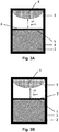
- FIGS Figures 3A to 10 Examples of the configuration of the first and / or second surface of the gas-permeable separating element 5 are shown in FIGS Figures 3A to 10 shown.
- the first surface of the gas-permeable separating element 5 is exemplarily processed and / or provided with a coating and / or the gas-permeable separating element 5 is formed from such a material that the first surface of the gas-permeable separating element 5 has an emissivity ⁇ reduced surface 6 is.
- the value of the emissivity ⁇ of the surface 6 with a reduced emissivity ⁇ is in a range between 0.01 and 0.5, preferably in a range between 0.2 and 0.4, for example 0.25. This leads to an increase in the axial temperature gradient. The difference between the temperatures T 1 and T 2 is thus increased.
- FIG. 3A schematically shown pattern of thin elevations on the first surface is of a purely illustrative nature and is used in each of the figures to identify a small emissivity ⁇ in the range between 0.01 and 0.5.
- the first surface which has changed its emissivity ⁇ , is flat or essentially flat and does not have the thin elevations shown schematically.
- the first surface of the gas-permeable separating element 5 is exemplarily processed and / or provided with a coating and / or the gas-permeable separating element 5 is formed from a material such that the first surface of the gas-permeable separating element 5 is a surface 7 with an increased emissivity ⁇ .
- the value of the emissivity ⁇ of the surface 7 with an increased emissivity ⁇ is in a range between 0.6 and 1.0, preferably in a range between 0.7 and 0.9, for example 0.85. This leads to a reduction in the axial temperature gradient. The difference between the temperatures T 1 and T 2 therefore decreases.
- the emissivity ⁇ of the surface 6 with a reduced emissivity ⁇ and the emissivity ⁇ of the surface 7 with an increased emissivity ⁇ are also in each case at the values mentioned above in the following examples.
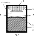
- the first surface of the gas-permeable separating element 5 has a radially inner and a radially outer section.
- the radially inner and radially outer sections are arranged concentrically to one another.
- the first surface of the gas-permeable separating element 5 is machined and / or coated in such a way that the radially inner section has a surface 6 that is reduced in emissivity ⁇ and the radially outer section has a surface 7 that is increased in emissivity ⁇ .
- the provision of the surface 6 with reduced emissivity ⁇ in the radially inner section and the provision of the surface 7 with increased emissivity ⁇ in the radially outer section leads to a local increase in the axial temperature gradient in front of the growth interface in the radially inner area compared to the radially outer area of the growth crest .
- the reduction in the radial temperature gradient ⁇ T rad advantageously leads to an improved crystal growth process.
- the reduction of the radial Temperature gradient ⁇ T rad advantageously brings about more uniform growth and a flatter growth interface.
- a plurality of concentrically arranged sections with an emissivity ⁇ increasing from the inside to the outside can be provided.
- the emissivity ⁇ can, for example, increase gradually or increase abruptly in the case of one or more radially outer sections.
- the arrangement of the surface 6 with reduced emissivity ⁇ and the surface 7 increased in emissivity ⁇ can also be performed inversely by machining and / or coating the first surface (not shown).
- the surface 6 reduced in emissivity ⁇ can therefore be provided in the radially outer section and the surface 7 increased in emissivity ⁇ can be provided in the radially inner section. This measure leads to an increase in the radial temperature gradient ⁇ T rad .
- a plurality of concentrically arranged sections can also be provided in the case of the inverse arrangement.
- the several concentrically arranged sections have an emissivity ⁇ that decreases from the inside to the outside.
- the emissivity ⁇ can decrease gradually or decrease abruptly in the case of one or more radially outer sections.
- the gas space 3 is formed from the first gas space 3a and the second gas space 3b as in the second growth crucible according to the invention.
- Both the first and the second surface now have an emissivity ⁇ reduced surface 6.
- the reduced emissivity ⁇ leads to an increased axial temperature gradient between the source material 2 and the gas-permeable separating element 5 and between the gas-permeable separating element 5 and the growing single crystal 4.
- This increases the total axial temperature gradient between the source material 2 and the single crystal 4.
- this also increases the heat flow and the material transport or the material flow.
- the gas space 3 is in turn formed from the first gas space 3a and the second gas space 3b (see Figure 2B ). Both the first and the second surface now have a surface 7 with an increased emissivity ⁇ .
- the increased emissivity ⁇ leads to a reduced axial temperature gradient between the source material 2 and the gas-permeable separating element 5 and between the gas-permeable separating element 5 and the growing single crystal 4. This reduces the total axial temperature gradient between the source material 2 and the single crystal 4.
- the heat flow and the material transport or the material flow can be reduced as a result.
- the total heat flow between source material 2 and single crystal 4 can be set in a particularly defined manner.
- the axial temperature gradient significantly determines the growth rate and growth kinetics (e.g. lateral overgrowth of defects, increase in SiC polytype stability).
- the gas space 3 is in turn formed from the first gas space 3a and the second gas space 3b.
- the second surface of the gas-permeable separating element 5 now has a radially inner and a radially outer section.
- the radially inner and radially outer sections are arranged concentrically to one another.
- the second surface of the gas-permeable separating element 5 is processed and / or coated in such a way that the radially inner section has a surface 6 that is reduced in emissivity ⁇ and the radially outer section has a surface 7 that is increased in emissivity ⁇ .
- the increased emissivity ⁇ in the radially outer section compared to the radially inner section of the second surface of the gas-permeable separating element 5 leads to a reduced axial temperature gradient in the outer area of the interface of the source material 2.
- the associated lower temperature in the outer area leads to reduced sublimation from Source material 2.
- the source material 2 is thereby consumed more evenly. This advantageously has a very stabilizing effect on a long crystal growth process. The crystal growth process is thus improved.
- a plurality of concentrically arranged sections with an emissivity ⁇ increasing from the inside to the outside can be provided on the second surface of the gas-permeable separating element 5.
- the emissivity ⁇ can increase gradually or increase abruptly in the case of one or more radially outer sections.
- the first surface provided with the reference number 8 has a defined setting of the emissivity ⁇ .
- the first surface 8 can in particular have the same arrangement as the second surface, preferably as described in the preceding paragraphs from a radially inner section and a radially outer section concentrically surrounding this section or from a plurality of sections arranged concentrically to one another.
- the configuration of the first surface 8 and the configuration of the second surface can, however, also differ. It goes without saying that the in Fig. 7
- the schematic dot-and-dash pattern shown on the first surface 8 is of a purely illustrative nature and is used here only to identify a first surface 8 configured according to the invention.
- the arrangement of the surface 6 with reduced emissivity ⁇ and the surface 7 increased in emissivity ⁇ on the second surface of the gas-permeable separating element 5 can also be carried out inversely (not shown).
- the surface 6 reduced in emissivity ⁇ can therefore be provided in the radially outer section and the surface 7 increased in emissivity ⁇ can be provided in the radially inner section.
- This measure leads to an increase in the axial temperature gradient in the outer area of the surface of the source material 2.
- the associated higher temperature in the outer area leads to increased sublimation from the source material 2.
- the source material 2 is thus consumed unevenly.
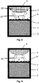
- the first surface 8 has a relief 9.
- a gas-permeable separating element is provided without a configuration according to the invention, in particular without a relief, the heat flows are bent inward from the first surface 8 in the direction of the growth interface of the single crystal 4.
- the growth interface of the single crystal 4 is formed in a convex shape. This also causes radial temperature gradients.
- the relief 9 of the ninth growth crucible according to the invention has a sawtooth profile with outwardly tilted concentrically arranged surfaces.
- the heat flows 10 from the first surface 8 are tilted radially outward in comparison to an axial direction and partially compensate for the heat flow direction directed inward towards the growth interface of the single crystal 4.
- the totality of the heat flows is therefore less concentrated on the center of the single crystal 4.
- the heat flows instead reach the radially outer edge region of the single crystal 4 to a greater extent and provide additional heating 11 there.
- a homogenization of the temperature of the single crystal 4 is achieved. This leads to a reduction in the radial temperature gradient. This advantageously improves the crystal growth process.
- the first surface 8 has a relief 9 with a sawtooth profile with inwardly tilted concentrically arranged surfaces.
- the heat flows 10 are tilted radially inward to a greater extent than in an axial direction.
- the heat flows reach the radially inner center of the single crystal 4 to a greater extent and cause a stronger one Cooling of the radially outer region of the single crystal 4. This leads to an increase in the radial temperature gradient.
- the gas space 3 is formed from the first gas space 3a and the second gas space 3b as in the second growth crucible according to the invention.
- both the first surface 8 and the second surface each have a relief 9 with a sawtooth profile.
- the first surface 8 has a relief 9 with a sawtooth profile with outwardly tilted concentrically arranged surfaces.
- the second surface has a relief 9 with a sawtooth profile with inwardly tilted concentrically arranged surfaces.
- other contours of the relief 9 are possible.
- the relief can have a sinusoidal, triangular, rectangular or trapezoidal contour.
- the heat flows 10 are tilted radially outward from the first surface 8 compared to an axial direction and thereby partially compensate for the inward direction of the heat flow towards the growth interface of the single crystal 4.
- the heat flows reach the radially outer edge region of the single crystal 4 to a greater extent and provide additional heating 11 there. This leads to a reduction in the radial temperature gradient. This advantageously improves the crystal growth process.
- Due to the inwardly tilted sawtooth profile on the second surface the heat flows 10 in the second gas space 3b are tilted radially inward compared to an axial direction.
- the associated higher temperature in the radially inner center leads to increased sublimation there from the source material 2.
- the source material 2 is thereby consumed more evenly.
- the radial temperature gradients in the source material 2 preferably have an amount of 0.1 K / cm to 10 K / cm for uniform sublimation, comparable to the case of the growing single crystal 4. This advantageously has a very stabilizing effect on a long crystal growth process.
- the crystal growth process is thus improved both by the relief 9 on the first surface 8 with the sawtooth profile tilted radially outward and by the relief 9 on the second surface with the sawtooth profile tilted radially inward.
- both the first surface 8 and the second surface can each have a relief 9 with a sawtooth profile with outwardly tilted concentrically arranged surfaces (not shown).
- the heat flows 10 are tilted radially outward in comparison to an axial direction.
- the heat flows more strongly into the radially outer edge regions of the single crystal 4 on the one hand and into the radially outer edge regions of the source material 2 on the other.
- this leads to a reduction in the radial temperature gradient in the region of the growth interface of the single crystal 4.
- the source material 2 is consumed more unevenly as a result.
- the sublimation rate and thus the concentration of the gaseous can be controlled in the direction of the source material 2 by locally controlling the surface temperature of the source material 2
- Precursor material, in particular the SiC gas species are locally adapted. In this way, especially with a large diameter of the growing single crystal 4, a homogeneous gas flow from the source material 2 to the single crystal 4 can be realized.
- the provision of the relief 9 can be combined with the provision of a predetermined emissivity ⁇ or a predetermined distribution of different emissivities ⁇ .
- a predetermined emissivity ⁇ or a predetermined distribution of different emissivities ⁇ can be provided on the first surface 8, on the second surface or on both surfaces of the gas-permeable separating element 5.
- a combination with one of the configurations described for the second to eighth growth crucibles according to the invention can be provided.
- the first 8 and / or second surface provided with a relief 9 can therefore additionally have a surface 6 with a reduced emissivity ⁇ and / or a surface 7 with an increased emissivity ⁇ .
- different sections with different emissivities ⁇ can be provided on the respective relief 9 of the first 8 and / or second surface.
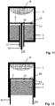
- a manipulator rod 14 is provided as an adjusting device for setting the position of the gas-permeable separating element 5.
- the manipulator rod 14 is made of graphite or TaC.
- the manipulator rod 14 extends axially centrally through the source material 2.
- the manipulator rod 14 is guided through a tube 12 running axially centrally through the source material 2.
- the source material 2 is provided as a solid volume body, in particular in the form of a dense cylinder block made of SiC or AlN.
- the manipulator rod 14 strikes the second surface of the gas-permeable separating element 5 centrally and is connected there to the gas-permeable separating element 5.
- Inert gas can be introduced into the interior of the growth crucible through a free space provided in the tube 12. The introduction of the inert gas advantageously prevents the gaseous precursor material from flowing out into the free space. This allows the growth crucible to be sealed.
- the manipulator rod 14 can therefore be moved in the axial direction of movement 15.
- the gas-permeable separating element 5 can be moved in the axial direction of movement 15 by the movement of the manipulator rod 14.
- the gas-permeable separating element 5 can thus be brought closer to the source material 2 or the single crystal 4.
- a manipulator cylinder 16 is provided as an adjusting device for setting the position of the gas-permeable separating element 5.
- the manipulator cylinder 16 is made of graphite or TaC.
- the manipulator cylinder 16 is a hollow cylinder which radially surrounds the source material 2.
- the source material 2 is provided as a solid volume body, in particular in the form of a dense cylinder block made of SiC or AlN.
- the gas-permeable separating element 5 forms an end face of the manipulator cylinder 16.
- the outer circumference of the gas-permeable separating element 5 is therefore connected to one end of the manipulator cylinder 16.
- a free space is provided between the manipulator cylinder 16 and the crucible wall 1.
- Inert gas can be introduced into the interior of the growth crucible through the free space. The introduction of the inert gas advantageously prevents the gaseous precursor material from flowing out into the free space. This allows the growth crucible to be sealed.
- the manipulator cylinder 16 can therefore be moved in the axial direction of movement 15.
- the gas-permeable separating element 5 can be moved in the axial direction of movement 15 by the movement of the manipulator cylinder 16.
- the gas-permeable separating element 5 can thus be brought closer to the source material 2 or the single crystal 4.
- the gas-permeable separating element 5 can be adjusted.
- the growth conditions in the gas space 3 can be kept constant during the growth process.
- the distance between the gas-permeable separating element 5 and the growing single crystal 4, in particular the distance from the convex growth interface of the single crystal 4 can be kept constant.
- the distance from the source material 2 can be kept constant by lowering the gas-permeable separating element 5.
- the provision of the manipulator rod 14 or of the manipulator cylinder 16 as an adjusting device for setting the position of the gas-permeable separating element 5 can in particular with the provision of a predetermined one
- a combination of providing the manipulator rod 14 or the manipulator cylinder 16 as an adjusting device with one of the configurations described for the second to eleventh growth crucibles according to the invention can be provided.
- a correspondingly processed, coated and / or structured first and / or second surface of the gas-permeable separating element 5 is in the Figures 11 and 12 each indicated purely by way of illustration and provided with the reference numeral 13. This enables a particularly stable growth process to be achieved.
Landscapes
- Chemical & Material Sciences (AREA)
- Engineering & Computer Science (AREA)
- Crystallography & Structural Chemistry (AREA)
- Materials Engineering (AREA)
- Metallurgy (AREA)
- Organic Chemistry (AREA)
- Inorganic Chemistry (AREA)
- Crystals, And After-Treatments Of Crystals (AREA)
Applications Claiming Priority (1)
| Application Number | Priority Date | Filing Date | Title |
|---|---|---|---|
| DE102020104226.4A DE102020104226A1 (de) | 2020-02-18 | 2020-02-18 | Verfahren zur Herstellung eines Einkristalls in einem Wachstumstiegel |
Publications (1)
| Publication Number | Publication Date |
|---|---|
| EP3868925A1 true EP3868925A1 (fr) | 2021-08-25 |
Family
ID=74505096
Family Applications (1)
| Application Number | Title | Priority Date | Filing Date |
|---|---|---|---|
| EP21154762.5A Pending EP3868925A1 (fr) | 2020-02-18 | 2021-02-02 | Procédé de fabrication d'un cristal unique dans un creuset de croissance |
Country Status (2)
| Country | Link |
|---|---|
| EP (1) | EP3868925A1 (fr) |
| DE (1) | DE102020104226A1 (fr) |
Cited By (1)
| Publication number | Priority date | Publication date | Assignee | Title |
|---|---|---|---|---|
| CN113981539A (zh) * | 2021-11-01 | 2022-01-28 | 深圳大学 | 一种多孔钨结构的晶体制备装置及氮化铝晶体制备方法 |
Citations (4)
| Publication number | Priority date | Publication date | Assignee | Title |
|---|---|---|---|---|
| JPH11255597A (ja) * | 1998-03-12 | 1999-09-21 | Denso Corp | 単結晶製造装置 |
| JP2000264795A (ja) * | 1999-03-23 | 2000-09-26 | Denso Corp | 炭化珪素単結晶の製造装置及び炭化珪素単結晶の製造方法 |
| EP1567696A1 (fr) * | 2003-07-31 | 2005-08-31 | SiCrystal Aktiengesellschaft | Procede et dispositif de production de monocristal de nitrure d'aluminium (aln), a paroi cupuliforme permeable aux gaz |
| US20140190413A1 (en) | 2011-06-14 | 2014-07-10 | Lg Innotek Co., Ltd. | Apparatus for fabricating ingot |
Family Cites Families (2)
| Publication number | Priority date | Publication date | Assignee | Title |
|---|---|---|---|---|
| WO1999014405A1 (fr) | 1997-09-12 | 1999-03-25 | Showa Denko Kabushiki Kaisha | Procede et appareil permettant de produire un cristal unique de carbure de silicium |
| DE102014217956B4 (de) | 2014-09-09 | 2018-05-09 | Sicrystal Ag | Herstellungsverfahren für einen Vanadium-dotierten SiC-Volumeneinkristall und Vanadium-dotiertes SiC-Substrat |
-
2020
- 2020-02-18 DE DE102020104226.4A patent/DE102020104226A1/de active Pending
-
2021
- 2021-02-02 EP EP21154762.5A patent/EP3868925A1/fr active Pending
Patent Citations (5)
| Publication number | Priority date | Publication date | Assignee | Title |
|---|---|---|---|---|
| JPH11255597A (ja) * | 1998-03-12 | 1999-09-21 | Denso Corp | 単結晶製造装置 |
| JP2000264795A (ja) * | 1999-03-23 | 2000-09-26 | Denso Corp | 炭化珪素単結晶の製造装置及び炭化珪素単結晶の製造方法 |
| EP1567696A1 (fr) * | 2003-07-31 | 2005-08-31 | SiCrystal Aktiengesellschaft | Procede et dispositif de production de monocristal de nitrure d'aluminium (aln), a paroi cupuliforme permeable aux gaz |
| EP1567696B1 (fr) * | 2003-07-31 | 2009-10-21 | SiCrystal Aktiengesellschaft | Procede et dispositif de production de monocristal de nitrure d'aluminium (aln), a paroi cupuliforme permeable aux gaz |
| US20140190413A1 (en) | 2011-06-14 | 2014-07-10 | Lg Innotek Co., Ltd. | Apparatus for fabricating ingot |
Non-Patent Citations (6)
| Title |
|---|
| ANONYMOUS: "Thermal emissivity Measurement", 7 August 2020 (2020-08-07), XP093181827, Retrieved from the Internet <URL:https://themacs-engineering.com/wp-content/uploads/2020/05/Emissivity-measurement.pdf> [retrieved on 20240403] * |
| AUTIO G ET AL: "The normal spectral emissivity of isotropic and anisotropic materials", CARBON, ELSEVIER OXFORD, GB, vol. 4, no. 1, 1 May 1966 (1966-05-01), pages 13 - 28, XP022844880, ISSN: 0008-6223, [retrieved on 19660501], DOI: 10.1016/0008-6223(66)90005-4 * |
| BIASETTO L ET AL: "Emissivity measurements of opaque gray bodies up to 2000 °C by a dual-frequency pyrometer", THE EUROPEAN PHYSICAL JOURNAL A ; HADRONS AND NUCLEI, SOCIETÀ ITALIANA DI FISICA, BO, vol. 38, no. 2, 6 November 2008 (2008-11-06), pages 167 - 171, XP019635741, ISSN: 1434-601X, DOI: 10.1140/EPJA/I2008-10666-6 * |
| P. J. WELLMANN: "Review of SiC crystal growth technology", SEMICONDUCTOR SCIENCE AND TECHNOLOGY, vol. 33, pages 103001, XP020330720, DOI: 10.1088/1361-6641/aad831 |
| SEO SEUNG-KUK ET AL: "Thermal Emissivity of Nuclear Graphite as a Function of Its Oxidation Degree (1) -Effects of Density, Porosity, and Microstructure-", CARBON LETTERS, vol. 10, no. 3, 30 September 2009 (2009-09-30), pages 225 - 229, XP093181857, ISSN: 1976-4251, DOI: 10.5714/CL.2009.10.3.225 * |
| YU. M. TAIROVV. F. TSVETKOV: "Investigation of Growth Processes of Ingots of Silicon Carbide Single Crystals", JOURNAL OF CRYSTAL GROWTH, vol. 43, 1978, pages 209 - 212 |
Cited By (1)
| Publication number | Priority date | Publication date | Assignee | Title |
|---|---|---|---|---|
| CN113981539A (zh) * | 2021-11-01 | 2022-01-28 | 深圳大学 | 一种多孔钨结构的晶体制备装置及氮化铝晶体制备方法 |
Also Published As
| Publication number | Publication date |
|---|---|
| DE102020104226A1 (de) | 2021-08-19 |
Similar Documents
| Publication | Publication Date | Title |
|---|---|---|
| DE602004001802T2 (de) | Vorrichtung und Verfahren zur Herstellung von Einkristallen durch Dampfphasenabscheidung | |
| EP1567696B1 (fr) | Procede et dispositif de production de monocristal de nitrure d'aluminium (aln), a paroi cupuliforme permeable aux gaz | |
| DE102010029755B4 (de) | Herstellungsverfahren für einen SiC-Volumeneinkristall ohne Facette und einkristallines SiC-Substrat mit homogener Widerstandsverteilung | |
| DE69904965T2 (de) | Herstellung von einkristallen aus aluminiumnitrid, siliziumkarbid und aluminiumnitrid-siliziumkarbid legierung | |
| DE60016771T2 (de) | Verfahren und vorrichtung zur herstellung von siliciumcarbid-kristallen | |
| DE102008063124B4 (de) | Herstellungsverfahren für einen gleichmäßig dotierten SiC-Volumeneinkristall und gleichmäßig dotiertes SiC-Substrat | |
| DE60105941T2 (de) | Verfahren und Vorrichtung zur Herstellung von Siliziumkarbidkristallen unter Verwendung von Quellgasen | |
| DE60125689T2 (de) | Verfahren und Vorrichtung zur Herstellung von Siliziumkarbidkristallen unter Verwendung von Quellegasen | |
| WO2022002745A1 (fr) | Unité de croissance de cristal pour produire un monocristal | |
| DE102008063129B4 (de) | Herstellungsverfahren für einen codotierten SiC-Volumeneinkristall und hochohmiges SiC-Substrat | |
| EP1099014B1 (fr) | DISPOSITIF ET PROCEDE POUR LA PRODUCTION D'AU MOINS UN MONOCRISTAL DE SiC | |
| DE102009016132B4 (de) | Verfahren zur Herstellung eines langen Volumeneinkristalls aus SiC oder AlN und langer Volumeneinkristall aus SiC oder AlN | |
| DE10050767A1 (de) | Verfahren und Vorrichtung zur Erzeugung von Einkristallen hoher Qualität | |
| EP3699328A1 (fr) | Procédé de fabrication pour un monocristal volumique de sic et dispositif de croissance correspondant | |
| DE69705545T2 (de) | Vorrichtung zur züchtung von grossen siliziumkarbideinkristallen | |
| EP4008811B1 (fr) | Procédé de fabrication d'un cristal unique dans un creuset de croissance | |
| DE102009004751B4 (de) | Thermisch isolierte Anordnung und Verfahren zur Herstellung eines SiC-Volumeneinkristalls | |
| WO2022194977A1 (fr) | Procédé de production d'un cristal unique massif de sic ayant une distribution non homogène de dislocation vis, et substrat de sic | |
| AT524249B1 (de) | Verfahren zum Züchten von Einkristallen | |
| EP3868925A1 (fr) | Procédé de fabrication d'un cristal unique dans un creuset de croissance | |
| DE112006002595B4 (de) | Herstellungsvorrichtung und Herstellungsverfahren für einen Einkristall-Halbleiter | |
| DE69406963T2 (de) | Hochharte Dünnschicht, sowie Verfahren zu deren Herstellung | |
| DE102022119343A1 (de) | Kristallzüchtungsvorrichtung und Verfahren zum Züchten eines Halbleiters | |
| DE19931332C2 (de) | Vorrichtung zur Herstellung eines SiC-Einkristalls mit einem doppelwandigen Tiegel | |
| DE102009016131B4 (de) | Herstellungsverfahren für einen SiC-Volumeneinkristall mittels einer Gasbarriere und versetzungsarmes einkristallines SiC-Substrat |
Legal Events
| Date | Code | Title | Description |
|---|---|---|---|
| PUAI | Public reference made under article 153(3) epc to a published international application that has entered the european phase |
Free format text: ORIGINAL CODE: 0009012 |
|
| STAA | Information on the status of an ep patent application or granted ep patent |
Free format text: STATUS: THE APPLICATION HAS BEEN PUBLISHED |
|
| AK | Designated contracting states |
Kind code of ref document: A1 Designated state(s): AL AT BE BG CH CY CZ DE DK EE ES FI FR GB GR HR HU IE IS IT LI LT LU LV MC MK MT NL NO PL PT RO RS SE SI SK SM TR |
|
| STAA | Information on the status of an ep patent application or granted ep patent |
Free format text: STATUS: REQUEST FOR EXAMINATION WAS MADE |
|
| 17P | Request for examination filed |
Effective date: 20220105 |
|
| RBV | Designated contracting states (corrected) |
Designated state(s): AL AT BE BG CH CY CZ DE DK EE ES FI FR GB GR HR HU IE IS IT LI LT LU LV MC MK MT NL NO PL PT RO RS SE SI SK SM TR |
|
| STAA | Information on the status of an ep patent application or granted ep patent |
Free format text: STATUS: EXAMINATION IS IN PROGRESS |
|
| 17Q | First examination report despatched |
Effective date: 20240711 |