EP3868964A1 - Sanitärarmatur mit einem nicht-axialen thermostatmischer - Google Patents
Sanitärarmatur mit einem nicht-axialen thermostatmischer Download PDFInfo
- Publication number
- EP3868964A1 EP3868964A1 EP20198684.1A EP20198684A EP3868964A1 EP 3868964 A1 EP3868964 A1 EP 3868964A1 EP 20198684 A EP20198684 A EP 20198684A EP 3868964 A1 EP3868964 A1 EP 3868964A1
- Authority
- EP
- European Patent Office
- Prior art keywords
- hot water
- slide
- expansion element
- water
- sanitary fitting
- Prior art date
- Legal status (The legal status is an assumption and is not a legal conclusion. Google has not performed a legal analysis and makes no representation as to the accuracy of the status listed.)
- Granted
Links
Images


Classifications
-
- E—FIXED CONSTRUCTIONS
- E03—WATER SUPPLY; SEWERAGE
- E03C—DOMESTIC PLUMBING INSTALLATIONS FOR FRESH WATER OR WASTE WATER; SINKS
- E03C1/00—Domestic plumbing installations for fresh water or waste water; Sinks
- E03C1/02—Plumbing installations for fresh water
- E03C1/04—Water-basin installations specially adapted to wash-basins or baths
- E03C1/0404—Constructional or functional features of the spout
-
- E—FIXED CONSTRUCTIONS
- E03—WATER SUPPLY; SEWERAGE
- E03C—DOMESTIC PLUMBING INSTALLATIONS FOR FRESH WATER OR WASTE WATER; SINKS
- E03C1/00—Domestic plumbing installations for fresh water or waste water; Sinks
- E03C1/02—Plumbing installations for fresh water
- E03C1/04—Water-basin installations specially adapted to wash-basins or baths
- E03C1/041—Water-basin installations specially adapted to wash-basins or baths having provisions against scalding, e.g. temperature limiting devices, external covers
-
- G—PHYSICS
- G05—CONTROLLING; REGULATING
- G05D—SYSTEMS FOR CONTROLLING OR REGULATING NON-ELECTRIC VARIABLES
- G05D23/00—Control of temperature
- G05D23/01—Control of temperature without auxiliary power
- G05D23/02—Control of temperature without auxiliary power with sensing element expanding and contracting in response to changes of temperature
- G05D23/021—Control of temperature without auxiliary power with sensing element expanding and contracting in response to changes of temperature the sensing element being a non-metallic solid, e.g. elastomer, paste
- G05D23/022—Control of temperature without auxiliary power with sensing element expanding and contracting in response to changes of temperature the sensing element being a non-metallic solid, e.g. elastomer, paste the sensing element being placed within a regulating fluid flow
-
- G—PHYSICS
- G05—CONTROLLING; REGULATING
- G05D—SYSTEMS FOR CONTROLLING OR REGULATING NON-ELECTRIC VARIABLES
- G05D23/00—Control of temperature
- G05D23/01—Control of temperature without auxiliary power
- G05D23/13—Control of temperature without auxiliary power by varying the mixing ratio of two fluids having different temperatures
- G05D23/1306—Control of temperature without auxiliary power by varying the mixing ratio of two fluids having different temperatures for liquids
- G05D23/132—Control of temperature without auxiliary power by varying the mixing ratio of two fluids having different temperatures for liquids with temperature sensing element
- G05D23/134—Control of temperature without auxiliary power by varying the mixing ratio of two fluids having different temperatures for liquids with temperature sensing element measuring the temperature of mixed fluid
Definitions
- the present invention relates to a sanitary fitting by means of which cold water and hot water can be mixed to form mixed water with a desired mixed water temperature.
- the mixed water can be made available in particular at wash basins, sinks, showers and / or bathtubs.
- Sanitary fittings can be designed, for example, in the manner of a single-lever mixer, which have a (single) operating lever for setting the mixed water temperature and a discharge amount of the mixed water.
- the temperature of the hot water supplied to the single-lever mixer is often not constant, but can, for example, be subject to fluctuations over the course of the day.
- the mixed water temperature of the mixed water produced by a mixing valve of the single-lever mixer fluctuates even if the operating lever is in the same position.
- a user of the sanitary fitting can therefore not rely on tapping mixed water with the desired mixed water temperature when the operating lever is in a certain position, but has to readjust the mixed water temperature regularly using the operating lever.
- Another disadvantage is that there is a risk of scalding if hot water with particularly high hot water temperatures is supplied to the single-lever mixer. Even hot water at a normal temperature can cause scalds. In addition, pressure fluctuations in the cold water or failure of the cold water supplied can lead to hazards.
- thermostatic mixer in front of a hot water inlet of the mixing valve of the sanitary fitting, through which hot water with a predetermined hot water temperature can be fed to the hot water inlet of the mixing valve.
- the thermostatic mixer mixes the hot water with cold water in advance in order to maintain a constant hot water temperature.
- the hot water pre-mixed in this way is then fed to the hot water inlet of the mixing valve.
- the disadvantage is that such thermostatic mixer take up a large amount of space that is often not available in the fitting housings of the sanitary fittings or that requires an enlargement of the fitting housings of the sanitary fittings.
- the object of the invention is therefore to at least partially solve the problems described with reference to the prior art and, in particular, to specify a sanitary fitting whose thermostatic mixer requires less space.
- the sanitary fitting can in particular be designed in the manner of a single-lever mixer and / or is used in particular to provide mixed water in a wash basin, sink, shower and / or bathtub.
- the sanitary fitting also has a fitting housing.
- the fitting housing can be at least partially made of plastic and / or Metal, such as brass or a zinc alloy, exist.
- the fitting housing can be fastened in particular to a carrier, such as a (kitchen) worktop, for example.
- the sanitary fitting has a mixing valve for mixing cold water and hot water to form mixed water.
- the mixing valve can be designed, for example, in the manner of a single-lever mixer cartridge and / or at least partially arranged in the fitting housing of the sanitary fitting.
- the mixing valve can have a mixing housing which in particular consists at least partially of plastic and / or is at least partially cylindrical.
- An adjusting lever which is used to actuate the mixing valve, is at least partially movably attached in the mixer housing.
- the adjusting lever is in particular connected to an operating lever of the sanitary fitting, for example by means of a screw connection or a plug connection.
- the adjusting lever can be rotatable about an axis of rotation, in particular for setting a mixed water temperature, and / or, in particular for setting a discharge amount of the mixed water, can be pivoted about a pivot axis (in particular orthogonal to the axis of rotation).
- the mixing valve can have a fixed control disk and a movable control disk.
- the fixed control disk and the movable control disk can each be designed in particular flat or disk-shaped.
- the fixed control disk and the movable control disk can at least partially consist of ceramic.
- the fixed control disk is in particular fixed, i. H.
- the movable control disc is movable (in particular rotatable with respect to the housing) in particular by means of the actuating lever on the fixed control disc.
- the sanitary fitting also has a thermostatic mixer for mixing cold water and hot water with the hot water.
- the cold water is supplied to the thermostatic mixer, for example from a public water supply network, in particular via a cold water line and / or the hot water is supplied to the thermostatic mixer, for example from the public water supply network and / or a hot water heater, in particular can be supplied via a hot water pipe.
- the cold water line and / or the hot water line can be, for example, a pipeline or a flexible hose.
- a cold water temperature of the cold water is in particular a maximum of 25 ° C (Celsius), preferably 1 ° C to 25 ° C, particularly preferably 5 ° C to 20 ° C and / or a hot water temperature of the hot water in particular a maximum of 100 ° C, preferably 25 ° C to 100 ° C, particularly preferably 55 ° C to 65 ° C.
- the cold water and hot water can be mixed with the hot water in particular in a hot water mixing room of the thermostatic mixer.
- the thermostatic mixer also comprises an expansion element and a slide which can be actuated by the expansion element.
- the expansion element extends in particular along a first longitudinal axis and / or is at least partially rotationally symmetrical about the at least one first longitudinal axis.
- the expansion element can at least partially consist of a wax and / or expand in particular as a function of the mixed water temperature of the mixed water, in particular parallel to the first longitudinal axis.
- the slide can at least partially consist of metal or plastic.
- the slide can in particular be at least partially cylindrical or tubular.
- the slide can extend along a second longitudinal axis.
- the slide is connected to the expansion element in such a way that a change in length of the expansion element leads to an actuation or movement of the slide, in particular in the direction of its second longitudinal axis.
- the slide can in particular change a gap width of a cold water regulating gap and / or a gap width of a hot water regulating gap of the thermostatic mixer.
- the cold water can be fed to the hot water mixing chamber of the thermostatic mixer, in particular via the cold water regulating gap, and / or the hot water can be fed to the hot water mixing chamber of the thermostatic mixer, in particular via the hot water regulating gap.
- the cold water regulating gap and / or the hot water regulating gap are formed in particular between the slide and a housing of the thermostatic mixer or a cartridge adapter of the mixing valve.
- the actuation of the slide leads in particular to a simultaneous change in the gap width of the cold water regulating gap and the Hot water control gap.
- An enlargement of the gap width of the cold water regulating gap leads in particular to a reduction in the hot water regulating gap.
- a reduction in the gap width of the cold water regulating gap leads in particular to an enlargement of the hot water regulating gap.
- an expansion or a lengthening of the expansion element leads in particular to an enlargement of the gap width of the cold water regulating gap and a reduction in the gap width of the hot water regulating gap.
- a shrinkage or shortening of the expansion element leads, in particular, to a reduction in the gap width of the cold water control gap and an increase in the gap width of the hot water control gap.
- a rising mixed water temperature of the mixed water can therefore lead to a falling hot water temperature of the hot water.
- a falling mixed water temperature of the mixed water can lead to a rising hot water temperature of the hot water. If the mixed water temperature of the mixed water exceeds, for example, a limit value, the slide can in particular completely close the hot water regulating gap.
- the hot water temperature of the hot water then corresponds to the cold water temperature of the cold water. In other words, the hot water in this case consists exclusively of the cold water.
- the hot water temperature of the hot water can be, for example, 1 ° C to 60 ° C.
- the hot water mixed by the thermostatic mixer can then be fed to the mixing valve, through which the hot water can be mixed with (further) cold water to form the mixed water.
- the expansion element and the slide are not arranged coaxially to one another.
- the thermostatic mixer can be arranged in the fitting housing, for example in a cylindrical free space and / or below the mixing valve.
- a first longitudinal axis of the expansion element and a second longitudinal axis of the slide can run parallel to one another. This can mean, in particular, that a distance is formed between the first longitudinal axis of the expansion element and the second longitudinal axis of the slide, which is dimensioned in particular orthogonally to the first longitudinal axis and the second longitudinal axis. As a result, the expansion element and the slide are arranged in particular next to one another.
- the slide can be actuated by the expansion element via a connecting element.
- the connecting element can at least partially consist of metal or plastic.
- the connecting element can be flat and / or designed in the manner of a disk.
- the connecting element can be at least partially S-shaped.
- the slide can in particular be coupled to the expansion element by the connecting element in such a way that a change in length of the expansion element leads to the actuation or adjustment of the slide.
- the connecting element can be adjustable against a spring by the expansion element.
- the spring can for example be designed in the manner of a helical spring.
- the spring can in particular generate a counterforce by which the connecting element and thus the slide fastened to the connecting element can be reset when the expansion element shrinks.
- the spring and the slide can in particular not be arranged coaxially to one another.
- the spring can have a third longitudinal axis which runs parallel to the first longitudinal axis of the expansion element and / or the second longitudinal axis of the slide.
- the slide and the connecting element can be connected to one another via a thread. As a result, a position of the slide relative to the connecting element and / or the expansion element can be adjusted.
- the connecting element can engage in a first groove of the expansion element and in a second groove of the slide.
- the first groove of the expansion element runs in particular around the first longitudinal axis of the expansion element and / or the second groove of the slide around the second longitudinal axis of the slide.
- the expansion element can be arranged in a first cavity of a housing of the thermostatic mixer and the slide can be arranged in a second cavity of the housing of the thermostatic mixer.
- the expansion element and the slide can be arranged spatially separated in the housing of the thermostatic mixer.
- the slide can have a hot water channel for the hot water.
- the slide can in particular be at least partially tubular.
- the hot water can thus be fed to the hot water mixing chamber of the thermostatic mixer through the slide valve and via the hot water regulating gap.
- the mixed water can at least partially flow around the expansion element.
- the expansion element can at least partially delimit a mixed water channel through which the mixed water mixed by the mixing valve can be fed to the outlet opening of the outlet.
- the Fig. 1 shows a first variant of a sanitary fitting 1 in a side view.
- the sanitary fitting 1 comprises a fitting housing 2 with an outlet 18 and an outlet opening 19.
- the sanitary fitting 1 comprises an operating lever 20 which can be pivoted about a horizontal axis to control a discharge quantity of mixed water and rotatable about a vertical axis to set a mixed water temperature of the mixed water .
- the operating lever 20 is provided with a Fig. 2 shown adjusting lever 21 of a mixing valve 3, which is designed here in the manner of a single-lever mixer cartridge.
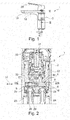
- the Fig. 2 shows the first variant embodiment of the sanitary fitting 1 in a longitudinal section along that in FIG Fig. 1 Section line II-II shown.
- a thermostatic mixer 4 is arranged for mixing cold water and hot water to form hot water.
- the thermostatic mixer 4 can be supplied with hot water via a hot water line 23 and cold water via a cold water line 24.
- the hot water line 23 and the cold water line 24 open into a cartridge adapter 22 which carries the mixing valve 3 in the fitting housing 2 of the sanitary fitting 1 and serves as a housing 15 for the thermostatic mixer 4.
- the hot water can be fed to a hot water mixing chamber 27 of the thermostatic mixer 4 via a hot water channel 25 of the housing 15 and a hot water regulating gap 26 of the thermostatic mixer 4.
- the cold water can be fed to the hot water mixing chamber 27 of the thermostatic mixer 4 via a first cold water channel 28 of the housing 15 and a cold water regulating gap 29 of the thermostatic mixer 4.
- the cold water can be fed to the mixing valve 3 via the first cold water channel 28 and a second cold water channel 30 of the housing 15.
- the thermostatic mixer 4 comprises a slide 6, by means of which a mixing ratio between the cold water and hot water mixed in the hot water mixing chamber 27 can be set.
- the slide 6 is by a in the Fig. 3 shown expansion element 5 can be actuated.
- the expansion element 5 has one in the Fig. 3 shown first longitudinal axis 7, in the direction of which the expansion element 5 can expand depending on the mixed water temperature of the mixed water.
- the resulting change in length of the expansion element 5 can be transferred to the slide 6 via a connecting element 9, so that the slide 6 can be adjusted in a direction of movement 31 by the expansion element 5 parallel to its second longitudinal axis 8.
- the second longitudinal axis 8 of the slide 6 extends here orthogonally to a housing longitudinal axis 33 of the housing 15 or the fitting housing 2.
- the movement of the slide 6 in the direction of movement 31 changes a gap width of the hot water regulating gap 26 and the cold water regulating gap 29, so that the mixing ratio changes between the cold water and hot water in the hot water mixing room and thus a hot water temperature of the mixed hot water changes.
- An extension of the expansion element 5 in the direction of its first longitudinal axis 7 leads to a reduction in the gap width of the hot water regulating gap 26 and an enlargement of the gap width of the cold water regulating gap 29, so that the hot water temperature of the hot water drops.
- a shortening of the expansion element 5 in the direction of its first longitudinal axis 7 leads to an enlargement of the gap width of the hot water regulating gap 26 and a reduction in the gap width of the cold water regulating gap 29, so that the hot water temperature of the hot water rises.
- the gap width of the hot water regulating gap 26 and the cold water regulating gap 29 is measured here parallel to the second longitudinal axis 8 of the slide 6 or parallel to the direction of movement 31 of the slide 6.
- the slide 6 can be adjusted by the expansion element 5 to such an extent that the hot water regulating gap 26 or the cold water regulating gap 29 are closed.
- the hot water temperature of the hot water then corresponds to a hot water temperature of the hot water or a cold water temperature of the cold water.
- the hot water mixed in the hot water mixing chamber 27 of the thermostatic mixer 4 can be fed to the mixing valve 3 via a hot water channel 32 of the housing 15, so that the cold water and the hot water can then be mixed through the mixing valve 3 to form the mixed water with the desired mixed water temperature.
- the mixed water is from the mixing valve 3 via one in the Fig. 3 partially to be recognized mixed water channel 37 in the Fig. 1 shown outlet opening 19 of the outlet 18 can be supplied.
- the Fig. 3 shows the first variant of the sanitary fitting 1 in a cross section along that in FIG Fig. 2 Section line III-III shown. It can be seen here that the expansion element 5 and the slide 6 are not arranged coaxially to one another. Instead, the first longitudinal axis 7 of the expansion element 5 and the second longitudinal axis 8 of the slide 6 run parallel and at a distance 34 from one another. The expansion element 5 and the slide 6 are thus arranged next to one another. In addition, the expansion element 5 is arranged in a first cavity 14 of the housing 15 or of the cartridge adapter 22 and the slide 6 is arranged in a second cavity 16 of the housing 15 or of the cartridge adapter 22.
- a first longitudinal end 35 of the expansion element 5 delimits the mixed water channel 37, so that the expansion element 5 through the in the Fig. 2 Mixing valve 3 shown mixed mixed water can at least partially flow around.
- the expansion element 5 can expand during operation of the sanitary fitting 1 as a function of the mixed water temperature of the mixed water in the mixed water channel 37 along its first longitudinal axis 7.
- the expansion element 5 makes contact with the connection element 9 at its second longitudinal end 36, so that a change in length of the expansion element 5 can be transmitted to the slide 6 via the connection element 9.
- the slide 6 is fastened to the connecting element 9 at a third longitudinal end 38 via a thread 11. The thread 11 enables the slide 6 to be adjusted.
- the slide 6 When the expansion element 5 extends along its first longitudinal axis 7, the slide 6 reduces the gap width of the hot water control gap 26 and increases the gap width of the cold water control gap 29 Connecting element 9 with a spring 10 in operative connection.
- the spring 10 is here in the manner of a helical spring and has a third longitudinal axis 39, which runs parallel to and at a distance from the first longitudinal axis 7 of the expansion element 5 and the second longitudinal axis 8 of the slide 6.
- the spring 10 is also not arranged coaxially to the expansion element 5 and / or to the slide 6.
- the spring 10 presses the connecting element 9 against the second longitudinal end 36 of the expansion element 5, so that the connecting element 9 and the slide 6 are held parallel to its first longitudinal axis 7 at the second longitudinal end 36 of the expansion element 5 when the expansion element 5 is shortened.
- the slide 6 increases the gap width of the hot water control gap 26 and reduces the gap width of the cold water control gap 29.
- the connecting element 9 extends from the spring 10 to the second longitudinal end 36 of the expansion element 5 (essentially ) S-shaped.
- the Fig. 4 shows a second variant of the sanitary fitting 1 in a longitudinal section.
- the sanitary fitting 1 has a fitting housing 2 which, like that in FIG Fig. 1
- the fitting housing 2 shown of the first variant of the sanitary fitting 1 can be formed.
- the fitting housing 2 can also have an outlet 18 with an outlet opening 19.
- the Fig. 4 the second variant of the sanitary fitting 1 in the area of the Fig. 1 Section line II-II shown of the first variant of the sanitary fitting 1.
- the second variant of the sanitary fitting 1 also has a mixing valve 3 and a thermostatic mixer 4.
- the thermostatic mixer 4 comprises an expansion element 5 which is connected to a slide 6 via a connection element 9.
- the connecting element 9 engages in a first groove 12 of the expansion element 5 and in a second groove 13 of the slide 6.
- the expansion element 5 and the slide 6 are not arranged coaxially to one another, but a first longitudinal axis 7 of the expansion element 5 and a second longitudinal axis 8 of the slide 6 run parallel and at a distance 34 from one another. Furthermore, the first longitudinal axis 7 and the second longitudinal axis 8 run parallel to a housing longitudinal axis 33 of a housing 15 of the thermostatic mixer 4 or the fitting housing 2 of the sanitary fitting 1.
- the expansion element 5 is in a first cavity 14 and the slide 6 in a second cavity 16 of the Housing 15 arranged.
- a hot water line 23 opens into the housing 15 which can be fed to the thermostatic mixer 4 hot water.
- a hot water channel 25 extends through the slide 6, so that the slide 6 is tubular.
- the hot water can be guided via the hot water channel 25 and through a hot water regulating gap 26 into a hot water mixing chamber 27 of the thermostatic mixer 4.
- the hot water regulating gap 26 is formed between an inner surface 17 of the slide 6 and a pin 40 of a cartridge adapter 22 of the mixing valve 3.
- a cold water line 24, not visible here opens into the housing 15.
- the cold water can be fed to the mixing valve 3 and an annular gap 41 running around the slide 6 via cold water lines in the housing 15, which are also not visible here.
- the cold water can be fed to the hot water mixing chamber 27 via a cold water regulating gap 29.
- the cold water regulating gap 29 is formed between an outer surface 42 of the slide 6 and the housing 15 of the thermostatic mixer 4.
- the expansion element 5 delimits a mixed water channel 37, via which mixed water mixed by the mixing valve 3 can be fed to an outlet opening 19 (not shown here).
- the expansion element 5 therefore expands during operation of the sanitary fitting 1 as a function of a mixed water temperature of the mixed water and moves the slide 6 via the connecting element 9 parallel to the second longitudinal axis 8 of the slide 6, so that a gap width of the hot water control gap 26 and a gap width of the cold water control gap 29 change. If the mixed water temperature of the mixed water increases, the expansion element 5 adjusts the slide 6 in such a way that the gap width of the hot water regulating gap 26 is reduced and the gap width of the cold water regulating gap 29 is increased.
- the expansion element 5 adjusts the slide 6 in such a way that the gap width of the hot water regulating gap 26 is enlarged and the gap width of the cold water regulating gap 29 is reduced.
- the expansion element 5 is pretensioned by a spring 10, which is designed here in the manner of a helical spring and is arranged in the mixed water channel 37.
- the hot water mixed by the thermostatic mixer 4 in the hot water mixing chamber 27 can be fed to the mixing valve 3 via a hot water channel 32, which is only partially visible here, and can be mixed with the cold water to form the mixed water.
- the Fig. 5 shows the second variant embodiment of the sanitary fitting 1 in a cross section along that in FIG Fig. 4 shown section line VV.
- the connection element 9, which connects the expansion element 5 to the slide 6, can be seen here in particular.
- the connecting element 9 is also (essentially) S-shaped.
- the thermostatic mixer of the sanitary fitting requires less space.
Landscapes
- Engineering & Computer Science (AREA)
- Physics & Mathematics (AREA)
- Hydrology & Water Resources (AREA)
- Automation & Control Theory (AREA)
- Health & Medical Sciences (AREA)
- Life Sciences & Earth Sciences (AREA)
- General Physics & Mathematics (AREA)
- Public Health (AREA)
- Water Supply & Treatment (AREA)
- Fluid Mechanics (AREA)
- Multiple-Way Valves (AREA)
- Domestic Plumbing Installations (AREA)
- Food-Manufacturing Devices (AREA)
- Endoscopes (AREA)
Abstract
Description
- Die vorliegende Erfindung betrifft eine Sanitärarmatur, durch die Kaltwasser und Heißwasser zu einem Mischwasser mit einer gewünschten Mischwassertemperatur mischbar ist. Mittels derartiger Sanitärarmaturen ist das Mischwasser insbesondere an Waschbecken, Spülbecken, Duschen und/oder Badewannen bereitstellbar.
- Sanitärarmaturen können beispielsweise nach Art eines Einhebelmischers ausgebildet sein, die einen (einzigen) Bedienhebel zur Einstellung der Mischwassertemperatur und einer Abgabemenge des Mischwassers aufweisen. Die Temperatur des dem Einhebelmischer zugeführten Heißwassers ist häufig nicht konstant, sondern kann, beispielsweise im Tagesverlauf, Schwankungen unterliegen. Hierdurch schwankt selbst bei identischer Stellung des Bedienhebels die Mischwassertemperatur des durch ein Mischventil des Einhebelmischers hergestellten Mischwassers. Ein Benutzer der Sanitärarmatur kann sich somit nicht darauf verlassen, bei einer bestimmten Stellung des Bedienhebels Mischwasser mit der gewünschten Mischwassertemperatur zu zapfen, sondern muss die Mischwassertemperatur über den Bedienhebel regelmäßig nachjustieren. Zudem ist nachteilig, dass eine Gefahr von Verbrühungen besteht, wenn dem Einhebelmischer Heißwasser mit besonders hohen Heißwassertemperaturen zugeführt wird. Auch normal temperiertes Heißwasser kann bereits zu Verbrühungen führen. Zudem können Druckschwankungen des Kaltwassers oder ein Ausfall des zugeführten Kaltwassers zu Gefahren führen.
- Es ist daher bereits bekannt, einem Warmwassereinlass des Mischventils der Sanitärarmatur einen Thermostatmischer vorzuordnen, durch den dem Warmwassereinlass des Mischventils Warmwasser mit einer vorgegebenen Warmwassertemperatur zuführbar ist. Hierzu mischt der Thermostatmischer das Heißwasser vorab mit Kaltwasser, um eine konstante Warmwassertemperatur zu erhalten. Das derart vorgemischte Warmwasser wird anschließend dem Warmwassereinlass des Mischventils zugeführt. Nachteilig ist, dass derartige Thermostatmischer einen großen Bauraum beanspruchen, der in Armaturengehäusen der Sanitärarmaturen häufig nicht zur Verfügung steht oder der eine Vergrößerung der Armaturengehäuse der Sanitärarmaturen erfordert.
- Aufgabe der Erfindung ist es daher, die mit Bezug auf den Stand der Technik geschilderten Probleme zumindest teilweise zu lösen und insbesondere eine Sanitärarmatur anzugeben, dessen Thermostatmischer einen geringeren Bauraumbedarf aufweist.
- Diese Aufgabe wird gelöst mit einer Sanitärarmatur gemäß den Merkmalen des unabhängigen Patentanspruchs. Weitere vorteilhafte Ausgestaltungen der Erfindung sind in den abhängigen Patentansprüchen angegeben. Es ist darauf hinzuweisen, dass die in den abhängigen Patentansprüchen einzeln aufgeführten Merkmale in beliebiger technologisch sinnvoller Weise miteinander kombiniert werden können und weitere Ausgestaltungen der Erfindung definieren. Darüber hinaus werden die in den Patentansprüchen angegebenen Merkmale in der Beschreibung näher präzisiert und erläutert, wobei weitere bevorzugte Ausgestaltungen der Erfindung dargestellt werden.
- Hierzu trägt eine Sanitärarmatur bei, die zumindest die folgenden Komponenten aufweist:
- ein Armaturengehäuse;
- ein Mischventil zum Mischen von Kaltwasser und Warmwasser zu einem Mischwasser; und
- ein Thermostatmischer zum Mischen von Kaltwasser und Heißwasser zu dem Warmwasser, der ein Dehnstoffelement und einen durch das Dehnstoffelement betätigbaren Schieber zum Einstellen eines Mischungsverhältnisses zwischen dem Kaltwasser und dem Heißwasser umfasst, wobei das Dehnstoffelement und der Schieber nicht koaxial zueinander angeordnet sind.
- Die Sanitärarmatur kann insbesondere nach Art eines Einhebelmischers ausgebildet sein und/oder dient insbesondere der Bereitstellung eines Mischwassers an einem Waschbecken, Spülbecken, Dusche und/oder Badewanne. Weiterhin weist die Sanitärarmatur ein Armaturengehäuse auf. Das Armaturengehäuse kann zumindest teilweise aus Kunststoff und/oder Metall, wie zum Beispiel Messing oder eine Zinklegierung, bestehen. Weiterhin ist das Armaturengehäuse insbesondere an einem Träger, wie zum Beispiel einer (Küchen-)Arbeitsplatte, befestigbar.
- Zudem weist die Sanitärarmatur ein Mischventil zum Mischen von Kaltwasser und Warmwasser zu einem Mischwasser auf. Das Mischventil kann beispielsweise nach Art einer Einhebelmischkartusche ausgebildet sein und/oder zumindest teilweise in dem Armaturengehäuse der Sanitärarmatur angeordnet sein. Das Mischventil kann ein Mischgehäuse aufweisen, das insbesondere zumindest teilweise aus Kunststoff besteht und/oder zumindest teilweise zylinderförmig ausgebildet ist. In dem Mischgehäuse ist zumindest teilweise ein Stellhebel beweglich befestigt, welcher der Betätigung des Mischventils dient. Der Stellhebel ist hierzu insbesondere mit einem Bedienhebel der Sanitärarmatur, beispielsweise mittels einer Schraubverbindung oder Steckverbindung, verbunden. Der Stellhebel kann, insbesondere zur Einstellung einer Mischwassertemperatur, um eine Drehachse drehbar und/oder, insbesondere zur Einstellung einer Abgabemenge des Mischwassers, um eine (insbesondere orthogonal zu der Drehachse verlaufenden) Schwenkachse schwenkbar sein. Weiterhin kann das Mischventil eine feststehende Steuerscheibe und eine bewegliche Steuerscheibe aufweisen. Die feststehende Steuerscheibe und die bewegliche Steuerscheibe können jeweils insbesondere flach bzw. scheibenförmig ausgebildet sein. Weiterhin können die feststehende Steuerscheibe und die bewegliche Steuerscheibe zumindest teilweise aus Keramik bestehen. Die feststehende Steuerscheibe ist insbesondere fest, d. h. insbesondere gegenüber dem Gehäuse nicht verschieblich oder nicht drehbar, in dem Gehäuse angeordnet, wohingegen die bewegliche Steuerscheibe insbesondere durch den Stellhebel auf der feststehenden Steuerscheibe bewegbar (insbesondere gegenüber dem Gehäuse drehbar) ist.
- Weiterhin weist die Sanitärarmatur einen Thermostatmischer zum Mischen von Kaltwasser und Heißwasser zu dem Warmwasser auf. Das Kaltwasser ist dem Thermostatmischer, beispielsweise von einem öffentlichen Wasserversorgungsnetz, insbesondere über eine Kaltwasserleitung und/oder das Heißwasser dem Thermostatmischer, beispielsweise von dem öffentlichen Wasserversorgungsnetz und/oder einem Heißwasserbereiter, insbesondere über eine Heißwasserleitung zuführbar. Bei der Kaltwasserleitung und/oder der Heißwasserleitung kann es sich beispielsweise um eine Rohrleitung oder einen flexiblen Schlauch handeln. Eine Kaltwassertemperatur des Kaltwassers beträgt insbesondere maximal 25 °C (Celsius), bevorzugt 1 °C bis 25 °C, besonders bevorzugt 5 °C bis 20 °C und/oder eine Heißwassertemperatur des Heißwassers insbesondere maximal 100 °C, bevorzugt 25 °C bis 100 °C, besonders bevorzugt 55 °C bis 65 °C. Das Kaltwasser und Heißwasser sind insbesondere in einem Warmwassermischraum des Thermostatmischers zu dem Warmwasser mischbar. Der Thermostatmischer umfasst zudem ein Dehnstoffelement und einen durch das Dehnstoffelement betätigbaren Schieber. Das Dehnstoffelement erstreckt sich insbesondere entlang einer ersten Längsachse und/oder ist zumindest teilweise rotationssymmetrisch um die zumindest eine erste Längsachse ausgebildet. Weiterhin kann das Dehnstoffelement zumindest teilweise aus einem Wachs bestehen und/oder sich insbesondere in Abhängigkeit von der Mischwassertemperatur des Mischwassers, insbesondere parallel zu der ersten Längsachse, ausdehnen. Der Schieber kann zumindest teilweise aus Metall oder Kunststoff bestehen. Weiterhin kann der Schieber insbesondere zumindest teilweise zylinderförmig oder rohrförmig ausgebildet sein. Zudem kann der Schieber sich entlang einer zweiten Längsachse erstrecken. Der Schieber ist derart mit dem Dehnstoffelement verbunden, dass eine Längenänderung des Dehnstoffelements zu einer Betätigung bzw. einer Bewegung des Schiebers, insbesondere in Richtung seiner zweiten Längsachse, führt. Durch die Betätigung bzw. Bewegung des Schiebers ist ein Mischungsverhältnis zwischen dem Kaltwasser und dem Heißwasser veränderbar, wodurch eine Warmwassertemperatur des gemischten Warmwassers durch den Thermostatmischer beeinflussbar ist. Hierzu kann der Schieber insbesondere eine Spaltbreite eines Kaltwasserregelspalts und/oder eine Spaltbreite eines Heißwasserregelspalts des Thermostatmischers verändern. Das Kaltwasser ist dem Warmwassermischraum des Thermostatmischers insbesondere über den Kaltwasserregelspalt und/oder das Heißwasser dem Warmwassermischraum des Thermostatmischers insbesondere über den Heißwasserregelspalt zuführbar. Der Kaltwasserregelspalt und/oder der Heißwasserregelspalt sind insbesondere zwischen dem Schieber und einem Gehäuse des Thermostatmischers oder einem Kartuschenadapter des Mischventils ausgebildet. Die Betätigung des Schiebers führt insbesondere zu einer gleichzeitigen Änderung der Spaltbreite des Kaltwasserregelspalts und des Heißwasserregelspalts. Eine Vergrößerung der Spaltbreite des Kaltwasserregelspalts führt dabei insbesondere zu einer Verkleinerung des Heißwasserregelspalts. Entsprechend führt eine Verkleinerung der Spaltbreite des Kaltwasserregelspalts insbesondere zu einer Vergrößerung des Heißwasserregelspalts. Weiterhin führt eine Ausdehnung bzw. eine Verlängerung des Dehnstoffelements insbesondere zu einer Vergrößerung der Spaltbreite des Kaltwasserregelspalts und einer Verkleinerung der Spaltbreite des Heißwasserregelspalts. Entsprechend führt eine Schrumpfung bzw. eine Verkürzung des Dehnstoffelements insbesondere zu einer Verkleinerung der Spaltbreite des Kaltwasserregelspalts und einer Vergrößerung der Spaltbreite des Heißwasserregelspalts. Eine steigende Mischwassertemperatur des Mischwassers kann somit zu einer sinkenden Warmwassertemperatur des Warmwassers führen. Weiterhin kann somit eine sinkende Mischwassertemperatur des Mischwassers zu einer steigenden Warmwassertemperatur des Warmwassers führen. Übersteigt die Mischwassertemperatur des Mischwassers beispielsweise einen Grenzwert, kann der Schieber den Heißwasserregelspalt insbesondere vollständig verschließen. Die Warmwassertemperatur des Warmwassers entspricht dann der Kaltwassertemperatur des Kaltwassers. Mit anderen Worten besteht das Warmwasser in diesem Fall ausschließlich aus dem Kaltwasser. Die Warmwassertemperatur des Warmwassers kann beispielsweise 1 °C bis 60 °C betragen. Das durch den Thermostatmischer gemischte Warmwasser ist anschließend dem Mischventil zuführbar, durch das das Warmwasser mit (weiterem) Kaltwasser zu dem Mischwasser mischbar ist. Das Dehnstoffelement und der Schieber sind nicht koaxial zueinander angeordnet. Dies kann insbesondere bedeuten, dass die erste Längsachse des Dehnstoffelements und die zweite Längsachse des Schiebers nicht miteinander fluchten. Weiterhin kann dies bedeuten, dass das Dehnstoffelement und der Schieber nicht axial angeordnet bzw. in Richtung ihrer Längsachsen nicht hintereinander angeordnet sind. Dies führt zu einem geringeren Bauraumbedarf des Thermostatmischers. Hierdurch kann der Thermostatmischer in dem Armaturengehäuse beispielsweise in einen zylinderförmigen Freiraum und/oder unterhalb des Mischventils angeordnet werden.
- Eine erste Längsachse des Dehnstoffelements und eine zweite Längsachse des Schiebers können parallel zueinander verlaufen. Dies kann insbesondere bedeuten, dass zwischen der ersten Längsachse des Dehnstoffelements und der zweiten Längsachse des Schiebers ein Abstand ausgebildet ist, der sich insbesondere orthogonal zu der ersten Längsachse und der zweiten Längsachse bemisst. Hierdurch sind das Dehnstoffelement und der Schieber insbesondere nebeneinander angeordnet.
- Der Schieber kann durch das Dehnstoffelement über ein Verbindungselement betätigbar sein. Das Verbindungselement kann zumindest teilweise aus Metall oder Kunststoff bestehen. Weiterhin kann das Verbindungselement flach und/oder nach Art einer Scheibe ausgebildet sein. Zudem kann das Verbindungselement zumindest teilweise S-förmig ausgebildet sein. Der Schieber kann durch das Verbindungselement insbesondere derart mit dem Dehnstoffelement gekoppelt sein, dass eine Längenänderung des Dehnstoffelements zur Betätigung bzw. Verstellung des Schiebers führt.
- Das Verbindungselement kann durch das Dehnstoffelement gegen eine Feder verstellbar sein. Die Feder kann beispielsweise nach Art einer Schraubenfeder ausgebildet sein. Die Feder kann insbesondere eine Gegenkraft erzeugen, durch die das Verbindungselement und somit der an dem Verbindungselement befestigte Schieber bei einem Schrumpfen des Dehnstoffelements rückstellbar sind.
- Die Feder und der Schieber können insbesondere nicht koaxial zueinander angeordnet sein. Insbesondere kann die Feder eine dritte Längsachse aufweisen, die parallel zu der ersten Längsachse des Dehnstoffelements und/oder der zweiten Längsachse des Schiebers verläuft.
- Der Schieber und das Verbindungselement können über ein Gewinde miteinander verbunden sein. Hierdurch ist eine Stellung des Schiebers relativ zu dem Verbindungselement und/oder dem Dehnstoffelement justierbar.
- Das Verbindungselement kann in eine erste Nut des Dehnstoffelements und in eine zweite Nut des Schiebers eingreifen. Die erste Nut des Dehnstoffelements verläuft insbesondere um die erste Längsachse des Dehnstoffelements und/oder die zweite Nut des Schiebers um die zweite Längsachse des Schiebers.
- Das Dehnstoffelement kann in einem ersten Hohlraum eines Gehäuses des Thermostatmischers und der Schieber in einem zweiten Hohlraum des Gehäuses des Thermostatmischers angeordnet sein. Mit anderen Worten können das Dehnstoffelement und der Schieber räumlich getrennt in dem Gehäuse des Thermostatmischers angeordnet sein.
- Der Schieber kann einen Heißwasserkanal für das Heißwasser aufweisen. Hierzu kann der Schieber insbesondere zumindest teilweise rohrförmig ausgebildet sein. Somit kann das Heißwasser durch den Schieber und über den Heißwasserregelspalt dem Warmwassermischraum des Thermostatmischers zuführbar sein.
- Das Dehnstoffelement kann zumindest teilweise von dem Mischwasser umströmbar sein. Hierzu kann das Dehnstoffelement zumindest teilweise einen Mischwasserkanal begrenzen, durch den das durch das Mischventil gemischte Mischwasser der Auslauföffnung des Auslaufs zuführbar ist.
- Die Erfindung sowie das technische Umfeld werden nachfolgend anhand der Figuren näher erläutert. Es ist darauf hinzuweisen, dass die Figuren besonders bevorzugte Ausführungsvarianten der Erfindung zeigen, diese jedoch nicht darauf beschränkt ist. Dabei sind gleiche Bauteile in den Figuren mit denselben Bezugszeichen versehen. Es zeigen beispielhaft und schematisch:
- Fig. 1:
- eine erste Ausführungsvariante einer Sanitärarmatur;
- Fig. 2:
- die erste Ausführungsvariante der Sanitärarmatur in einem Längsschnitt;
- Fig. 3:
- die erste Ausführungsvariante der Sanitärarmatur in einem Querschnitt;
- Fig. 4:
- zweite Ausführungsvariante einer Sanitärarmatur in einem Längsschnitt; und
- Fig. 5:
- die zweite Ausführungsvariante der Sanitärarmatur in einem Querschnitt.
- Die
Fig. 1 zeigt eine erste Ausführungsvariante einer Sanitärarmatur 1 in einer Seitenansicht. Die Sanitärarmatur 1 umfasst ein Armaturengehäuse 2 mit einem Auslauf 18 und einer Auslauföffnung 19. Weiterhin umfasst die Sanitärarmatur 1 einen Bedienhebel 20, der zur Steuerung einer Abgabemenge eines Mischwassers um eine horizontale Achse schwenkbar und zur Einstellung einer Mischwassertemperatur des Mischwassers um eine vertikale Achse drehbar ist. Hierzu ist der Bedienhebel 20 mit einem in derFig. 2 gezeigten Stellhebel 21 eines Mischventils 3 verbunden, das hier nach Art einer Einhebelmischkartusche ausgebildet ist. - Die
Fig. 2 zeigt die erste Ausführungsvariante der Sanitärarmatur 1 in einem Längsschnitt entlang der in derFig. 1 gezeigten Schnittlinie II-II. In dem Armaturengehäuse 2 der Sanitärarmatur 1 ist ein Thermostatmischer 4 zum Mischen von Kaltwasser und Heißwasser zu einem Warmwasser angeordnet. Hierzu ist dem Thermostatmischer 4 Heißwasser über eine Heißwasserleitung 23 und Kaltwasser über eine Kaltwasserleitung 24 zuführbar. Die Heißwasserleitung 23 und die Kaltwasserleitung 24 münden in einen Kartuschenadapter 22, der das Mischventil 3 in dem Armaturengehäuse 2 der Sanitärarmatur 1 trägt und als Gehäuse 15 für den Thermostatmischer 4 dient. Das Heißwasser ist über einen Heißwasserkanal 25 des Gehäuses 15 und einen Heißwasserregelspalt 26 des Thermostatmischers 4 einem Warmwassermischraum 27 des Thermostatmischers 4 zuführbar. Das Kaltwasser ist über einen ersten Kaltwasserkanal 28 des Gehäuses 15 und einen Kaltwasserregelspalt 29 des Thermostatmischers 4 dem Warmwassermischraum 27 des Thermostatmischers 4 zuführbar. Zudem ist das Kaltwasser über den ersten Kaltwasserkanal 28 und einen zweiten Kaltwasserkanal 30 des Gehäuses 15 dem Mischventil 3 zuführbar. - Der Thermostatmischer 4 umfasst einen Schieber 6, mittels dem ein Mischungsverhältnis zwischen dem in dem Warmwassermischraum 27 gemischten Kaltwasser und Heißwasser einstellbar ist. Hierzu ist der Schieber 6 durch ein in der
Fig. 3 gezeigtes Dehnstoffelement 5 betätigbar. Das Dehnstoffelement 5 weist eine in derFig. 3 gezeigte erste Längsachse 7 auf, in dessen Richtung sich das Dehnstoffelement 5 in Abhängigkeit von der Mischwassertemperatur des Mischwassers ausdehnen kann. Die daraus folgende Längenänderung des Dehnstoffelements 5 ist über ein Verbindungselement 9 auf den Schieber 6 übertragbar, sodass der Schieber 6 durch das Dehnstoffelement 5 parallel zu seiner zweiten Längsachse 8 in eine Bewegungsrichtung 31 verstellbar ist. Die zweite Längsachse 8 des Schiebers 6 erstreckt sich hier orthogonal zu einer Gehäuselängsachse 33 des Gehäuses 15 bzw. des Armaturengehäuses 2. Die Bewegung des Schiebers 6 in der Bewegungsrichtung 31 bewirkt eine Änderung einer Spaltbreite des Heißwasserregelspalts 26 und des Kaltwasserregelspalts 29, sodass sich das Mischungsverhältnis zwischen dem Kaltwasser und Heißwasser in dem Warmwassermischraum und somit eine Warmwassertemperatur des gemischten Warmwassers ändert. Eine Verlängerung des Dehnstoffelements 5 in Richtung seiner ersten Längsachse 7 führt zu einer Verringerung der Spaltbreite des Heißwasserregelspalts 26 und einer Vergrößerung der Spaltbreite des Kaltwasserregelspalts 29, sodass die Warmwassertemperatur des Warmwassers sinkt. Eine Verkürzung des Dehnstoffelements 5 in Richtung seiner ersten Längsachse 7 führt zu einer Vergrößerung der Spaltbreite des Heißwasserregelspalts 26 und einer Verringerung der Spaltbreite des Kaltwasserregelspalts 29, sodass die Warmwassertemperatur des Warmwassers steigt. Die Spaltbreite des Heißwasserregelspalts 26 und des Kaltwasserregelspalts 29 bemisst sich hier parallel zu der zweiten Längsachse 8 des Schiebers 6 bzw. parallel zu der Bewegungsrichtung 31 des Schiebers 6. Der Schieber 6 ist durch das Dehnstoffelement 5 soweit verstellbar, dass der Heißwasserregelspalt 26 oder der Kaltwasserregelspalt 29 geschlossen sind. Die Warmwassertemperatur des Warmwassers entspricht dann einer Heißwassertemperatur des Heißwassers oder einer Kaltwassertemperatur des Kaltwassers. - Das in dem Warmwassermischraum 27 des Thermostatmischers 4 gemischte Warmwasser ist über einen Warmwasserkanal 32 des Gehäuses 15 dem Mischventil 3 zuführbar, sodass anschließend das Kaltwasser und das Warmwasser durch das Mischventil 3 zu dem Mischwasser mit der gewünschten Mischwassertemperatur mischbar sind. Das Mischwasser ist von dem Mischventil 3 über einen in der
Fig. 3 teilweise zu erkennenden Mischwasserkanal 37 der in derFig. 1 gezeigten Auslauföffnung 19 des Auslaufs 18 zuführbar. - Die
Fig. 3 zeigt die erste Ausführungsvariante der Sanitärarmatur 1 in einem Querschnitt entlang der in derFig. 2 gezeigten Schnittlinie III-III. Zu erkennen ist hier, dass das Dehnstoffelement 5 und der Schieber 6 nicht koaxial zueinander angeordnet sind. Stattdessen verlaufen die erste Längsachse 7 des Dehnstoffelements 5 und die zweite Längsachse 8 des Schiebers 6 parallel und mit einem Abstand 34 zueinander. Das Dehnstoffelement 5 und der Schieber 6 sind somit nebeneinander angeordnet. Zudem ist das Dehnstoffelement 5 in einem ersten Hohlraum 14 des Gehäuses 15 bzw. des Kartuschenadapters 22 und der Schieber 6 in einem zweiten Hohlraum 16 des Gehäuses 15 bzw. des Kartuschenadapters 22 angeordnet. Ein erstes längsseitiges Ende 35 des Dehnstoffelements 5 begrenzt den Mischwasserkanal 37, sodass das Dehnstoffelement 5 durch das in derFig. 2 gezeigte Mischventil 3 gemischte Mischwasser zumindest teilweise umströmbar ist. Hierdurch kann sich das Dehnstoffelement 5 im Betrieb der Sanitärarmatur 1 in Abhängigkeit der Mischwassertemperatur des Mischwassers in dem Mischwasserkanal 37 entlang seiner ersten Längsachse 7 ausdehnen. Das Dehnstoffelement 5 kontaktiert an seinem zweiten längsseitigen Ende 36 das Verbindungselement 9, sodass eine Längenänderung des Dehnstoffelements 5 über das Verbindungselement 9 auf den Schieber 6 übertragbar ist. Hierzu ist der Schieber 6 an einem dritten längsseitigen Ende 38 über ein Gewinde 11 an dem Verbindungselement 9 befestigt. Das Gewinde 11 ermöglicht eine Justierung des Schiebers 6. Bei einer Ausdehnung des Dehnstoffelements 5 entlang seiner ersten Längsachse 7 verringert der Schieber 6 die Spaltbreite des Heißwasserregelspalts 26 und vergrößert die Spaltbreite des Kaltwasserregelspalts 29. Auf einer dem Dehnstoffelement 5 gegenüberliegenden Seite des Schiebers 6 steht das Verbindungselement 9 mit einer Feder 10 in Wirkverbindung. Die Feder 10 ist hier nach Art einer Schraubenfeder ausgebildet und weist eine dritte Längsachse 39 auf, die parallel und mit Abstand zu der ersten Längsachse 7 des Dehnstoffelements 5 und der zweiten Längsachse 8 des Schiebers 6 verläuft. Somit ist die Feder 10 ebenfalls nicht koaxial zu dem Dehnstoffelement 5 und/oder zu dem Schieber 6 angeordnet. Die Feder 10 drückt das Verbindungselement 9 gegen das zweite längsseitige Ende 36 des Dehnstoffelements 5, sodass das Verbindungselement 9 und der Schieber 6 bei einer Verkürzung des Dehnstoffelements 5 parallel zu seiner ersten Längsachse 7 an dem zweiten längsseitigen Ende 36 des Dehnstoffelements 5 gehalten wird. Bei einer Verkürzung des Dehnstoffelements 5 entlang seiner ersten Längsachse 7 vergrößert der Schieber 6 die Spaltbreite des Heißwasserregelspalts 26 und verringert die Spaltbreite des Kaltwasserregelspalts 29. Das Verbindungselement 9 erstreckt sich von der Feder 10 bis zu dem zweiten längsseitigen Ende 36 des Dehnstoffelements 5 (im Wesentlichen) S-förmig. - Die
Fig. 4 zeigt eine zweite Ausführungsvariante der Sanitärarmatur 1 in einem Längsschnitt. Die Sanitärarmatur 1 weist ein Armaturengehäuse 2 auf, das wie das in derFig. 1 gezeigte Armaturengehäuse 2 der ersten Ausführungsvariante der Sanitärarmatur 1 ausgebildet sein kann. Insbesondere kann das Armaturengehäuse 2 ebenfalls einen Auslauf 18 mit einer Auslauföffnung 19 aufweisen. Weiterhin zeigt dieFig. 4 die zweite Ausführungsvariante der Sanitärarmatur 1 im Bereich der in derFig. 1 gezeigten Schnittlinie II-II der ersten Ausführungsvariante der Sanitärarmatur 1. Die zweite Ausführungsvariante der Sanitärarmatur 1 weist ebenfalls ein Mischventil 3 und einen Thermostatmischer 4 auf. Der Thermostatmischer 4 umfasst ein Dehnstoffelement 5, das über ein Verbindungselement 9 mit einem Schieber 6 verbunden ist. Hierzu greift das Verbindungselement 9 in eine erste Nut 12 des Dehnstoffelements 5 und in eine zweite Nut 13 des Schiebers 6 ein. Das Dehnstoffelement 5 und der Schieber 6 sind nicht koaxial zueinander angeordnet, sondern eine erste Längsachse 7 des Dehnstoffelements 5 und eine zweite Längsachse 8 des Schiebers 6 verlaufen parallel und mit einem Abstand 34 zueinander. Weiterhin verlaufen die erste Längsachse 7 und die zweite Längsachse 8 parallel zu einer Gehäuselängsachse 33 eines Gehäuses 15 des Thermostatmischers 4 bzw. des Armaturengehäuses 2 der Sanitärarmatur 1. Das Dehnstoffelement 5 ist in einem ersten Hohlraum 14 und der Schieber 6 in einem zweiten Hohlraum 16 des Gehäuses 15 angeordnet. In das Gehäuse 15 mündet einer Heißwasserleitung 23, über die dem Thermostatmischer 4 Heißwasser zuführbar ist. Durch den Schieber 6 erstreckt sich ein Heißwasserkanal 25, sodass der Schieber 6 rohrförmig ausgebildet ist. Das Heißwasser ist über den Heißwasserkanal 25 und durch einen Heißwasserregelspalt 26 in einen Warmwassermischraum 27 des Thermostatmischers 4 führbar. Der Heißwasserregelspalt 26 ist zwischen einer Innenfläche 17 des Schiebers 6 und einem Zapfen 40 eines Kartuschenadapters 22 des Mischventils 3 ausgebildet. Weiterhin mündet in das Gehäuse 15 eine hier nicht sichtbare Kaltwasserleitung 24. Über hier ebenfalls nicht sichtbare Kaltwasserleitungen in dem Gehäuse 15 ist das Kaltwasser dem Mischventil 3 und einem um den Schieber 6 verlaufenden Ringspalt 41 zuführbar. Das Kaltwasser ist dem Warmwassermischraum 27 über einen Kaltwasserregelspalt 29 zuführbar. Der Kaltwasserregelspalt 29 ist zwischen einer Außenfläche 42 des Schiebers 6 und dem Gehäuse 15 des Thermostatmischers 4 ausgebildet. - Das Dehnstoffelement 5 begrenzt einen Mischwasserkanal 37, über den ein durch das Mischventil 3 gemischtes Mischwasser einer hier nicht gezeigten Auslauföffnung 19 zuführbar ist. Das Dehnstoffelement 5 dehnt sich daher im Betrieb der Sanitärarmatur 1 in Abhängigkeit einer Mischwassertemperatur des Mischwassers aus und verstellt dabei den Schieber 6 über das Verbindungselement 9 parallel zu der zweiten Längsachse 8 des Schiebers 6, sodass sich eine Spaltbreite des Heißwasserregelspalts 26 und eine Spaltbreite des Kaltwasserregelspalts 29 ändern. Steigt die Mischwassertemperatur des Mischwassers, verstellt das Dehnstoffelement 5 den Schieber 6 derart, dass die Spaltbreite des Heißwasserregelspalts 26 verringert und die Spaltbreite des Kaltwasserregelspalts 29 vergrößert wird. Sinkt die Mischwassertemperatur des Mischwassers, verstellt das Dehnstoffelement 5 den Schieber 6 derart, dass die Spaltbreite des Heißwasserregelspalts 26 vergrößert und die Spaltbreite des Kaltwasserregelspalts 29 verringert wird. Hierzu ist das Dehnstoffelement 5 durch eine Feder 10, die hier nach Art einer Schraubenfeder ausgebildet und in dem Mischwasserkanal 37 angeordnet ist, vorgespannt. Das durch den Thermostatmischer 4 in dem Warmwassermischraum 27 gemischte Warmwasser ist dem Mischventil 3 über einen hier nur teilweise sichtbaren Warmwasserkanal 32 zuführbar und zusammen mit dem Kaltwasser zu dem Mischwasser mischbar.
- Die
Fig. 5 zeigt die zweite Ausführungsvariante der Sanitärarmatur 1 in einem Querschnitt entlang der in derFig. 4 gezeigten Schnittlinie V-V. Zu erkennen ist hier insbesondere das Verbindungselement 9, dass das Dehnstoffelement 5 mit dem Schieber 6 verbindet. Das Verbindungselement 9 ist ebenfalls (im Wesentlichen) S-förmig ausgebildet. - Durch die vorliegende Erfindung weist der Thermostatmischer der Sanitärarmatur einen geringeren Bauraumbedarf auf.
-
- 1
- Sanitärarmatur
- 2
- Armaturengehäuse
- 3
- Mischventil
- 4
- Thermostatmischer
- 5
- Dehnstoffelement
- 6
- Schieber
- 7
- erste Längsachse
- 8
- zweite Längsachse
- 9
- Verbindungselement
- 10
- Feder
- 11
- Gewinde
- 12
- erste Nut
- 13
- zweite Nut
- 14
- erster Hohlraum
- 15
- Gehäuse
- 16
- zweiter Hohlraum
- 17
- Innenfläche
- 18
- Auslauf
- 19
- Auslauföffnung
- 20
- Bedienhebel
- 21
- Stellhebel
- 22
- Kartuschenadapter
- 23
- Heißwasserleitung
- 24
- Kaltwasserleitung
- 25
- Heißwasserkanal
- 26
- Heißwasserregelspalt
- 27
- Warmwassermischraum
- 28
- erster Kaltwasserkanal
- 29
- Kaltwasserregelspalt
- 30
- zweiter Kaltwasserkanal
- 31
- Bewegungsrichtung
- 32
- Warmwasserkanal
- 33
- Gehäuselängsachse
- 34
- Abstand
- 35
- erstes längsseitiges Ende
- 36
- zweites längsseitiges Ende
- 37
- Mischwasserkanal
- 38
- drittes längsseitiges Ende
- 39
- dritte Längsachse
- 40
- Zapfen
- 41
- Ringspalt
- 42
- Außenfläche
Claims (10)
- Sanitärarmatur (1), zumindest aufweisend:- ein Armaturengehäuse (2);- ein Mischventil (3) zum Mischen von Kaltwasser und Warmwasser zu einem Mischwasser; und- ein Thermostatmischer (4) zum Mischen von Kaltwasser und Heißwasser zu dem Warmwasser, der ein Dehnstoffelement (5) und einen durch das Dehnstoffelement (5) betätigbaren Schieber (6) zum Einstellen eines Mischungsverhältnisses zwischen dem Kaltwasser und dem Heißwasser umfasst, wobei das Dehnstoffelement (5) und der Schieber (6) nicht koaxial zueinander angeordnet sind.
- Sanitärarmatur (1) nach Patentanspruch 1, wobei eine erste Längsachse (7) des Dehnstoffelements (5) und eine zweite Längsachse (8) des Schiebers (6) parallel zueinander verlaufen.
- Sanitärarmatur (1) nach einem der vorhergehenden Patentansprüche, wobei der Schieber (6) durch das Dehnstoffelement (5) über ein Verbindungselement (9) betätigbar ist.
- Sanitärarmatur (1) nach Patentanspruch 3, wobei das Verbindungselement (9) durch das Dehnstoffelement (5) gegen eine Feder (10) verstellbar ist.
- Sanitärarmatur (1) nach Patentanspruch 4, wobei die Feder (10) und der Schieber (6) nicht koaxial zueinander angeordnet sind.
- Sanitärarmatur (1) nach einem der Patentansprüche 3 bis 5, wobei der Schieber (6) und das Verbindungselement (9) über ein Gewinde (11) miteinander verbunden sind.
- Sanitärarmatur (1) nach einem der Patentansprüche 3 bis 6, wobei das Verbindungselement (9) in eine erste Nut (12) des Dehnstoffelements (5) und in eine zweite Nut (13) des Schiebers (6) eingreift.
- Sanitärarmatur (1) nach einem der vorhergehenden Patentansprüche, wobei das Dehnstoffelement (5) in einem ersten Hohlraum (14) eines Gehäuses (15) des Thermostatmischers (4) und der Schieber (6) in einem zweiten Hohlraum (16) des Gehäuses (15) des Thermostatmischers (4) angeordnet ist.
- Sanitärarmatur (1) nach einem der vorhergehenden Patentansprüche, wobei der Schieber (6) einen Heißwasserkanal (25) für das Heißwasser aufweist.
- Sanitärarmatur (1) nach einem der vorhergehenden Patentansprüche, wobei das Dehnstoffelement (5) zumindest teilweise von dem Mischwasser umströmbar ist.
Applications Claiming Priority (1)
| Application Number | Priority Date | Filing Date | Title |
|---|---|---|---|
| DE102020104759.2A DE102020104759A1 (de) | 2020-02-24 | 2020-02-24 | Sanitärarmatur mit einem nicht-axialen Thermostatmischer |
Publications (2)
| Publication Number | Publication Date |
|---|---|
| EP3868964A1 true EP3868964A1 (de) | 2021-08-25 |
| EP3868964B1 EP3868964B1 (de) | 2022-11-02 |
Family
ID=72665113
Family Applications (1)
| Application Number | Title | Priority Date | Filing Date |
|---|---|---|---|
| EP20198684.1A Active EP3868964B1 (de) | 2020-02-24 | 2020-09-28 | Sanitärarmatur mit einem nicht-axialen thermostatmischer |
Country Status (4)
| Country | Link |
|---|---|
| EP (1) | EP3868964B1 (de) |
| DE (1) | DE102020104759A1 (de) |
| ES (1) | ES2937971T3 (de) |
| FI (1) | FI3868964T3 (de) |
Cited By (1)
| Publication number | Priority date | Publication date | Assignee | Title |
|---|---|---|---|---|
| EP4386148A1 (de) * | 2022-12-12 | 2024-06-19 | Grohe AG | Sanitärarmatur |
Citations (5)
| Publication number | Priority date | Publication date | Assignee | Title |
|---|---|---|---|---|
| DE68914166T2 (de) * | 1988-01-11 | 1994-10-20 | Delafon Jacob Fa | Thermostatisches Mischventil. |
| DE102009007538A1 (de) * | 2009-02-04 | 2010-08-05 | Kludi Gmbh & Co. Kg | Sanitärarmatur |
| US20180059693A1 (en) * | 2015-03-06 | 2018-03-01 | Huber Cisal Industrie S.P.A. | Mixing valve assembly, tap and plant provided with said valve assembly |
| DE112016003514T5 (de) * | 2015-08-03 | 2018-04-19 | Vernet | Mischeinheit und Mischbatterie, die eine derartige Mischeinheit umfasst |
| US10025326B2 (en) * | 2012-08-30 | 2018-07-17 | Riobel Inc. | Thermostatic mixer valve |
Family Cites Families (3)
| Publication number | Priority date | Publication date | Assignee | Title |
|---|---|---|---|---|
| DE3041979C2 (de) | 1980-11-07 | 1984-09-20 | Fa. Knebel & Röttger, 5860 Iserlohn | Sanitäres Mischventil |
| DE102010028986A1 (de) | 2010-05-14 | 2011-11-17 | Kludi Gmbh & Co. Kg | Waschtischarmatur mit Sicherheitstemperaturbegrenzer |
| LU91784B1 (fr) | 2011-01-27 | 2012-07-30 | Claude Waudoit | Robinet mitigeur economiseur d'eau |
-
2020
- 2020-02-24 DE DE102020104759.2A patent/DE102020104759A1/de not_active Withdrawn
- 2020-09-28 ES ES20198684T patent/ES2937971T3/es active Active
- 2020-09-28 EP EP20198684.1A patent/EP3868964B1/de active Active
- 2020-09-28 FI FIEP20198684.1T patent/FI3868964T3/fi active
Patent Citations (5)
| Publication number | Priority date | Publication date | Assignee | Title |
|---|---|---|---|---|
| DE68914166T2 (de) * | 1988-01-11 | 1994-10-20 | Delafon Jacob Fa | Thermostatisches Mischventil. |
| DE102009007538A1 (de) * | 2009-02-04 | 2010-08-05 | Kludi Gmbh & Co. Kg | Sanitärarmatur |
| US10025326B2 (en) * | 2012-08-30 | 2018-07-17 | Riobel Inc. | Thermostatic mixer valve |
| US20180059693A1 (en) * | 2015-03-06 | 2018-03-01 | Huber Cisal Industrie S.P.A. | Mixing valve assembly, tap and plant provided with said valve assembly |
| DE112016003514T5 (de) * | 2015-08-03 | 2018-04-19 | Vernet | Mischeinheit und Mischbatterie, die eine derartige Mischeinheit umfasst |
Cited By (1)
| Publication number | Priority date | Publication date | Assignee | Title |
|---|---|---|---|---|
| EP4386148A1 (de) * | 2022-12-12 | 2024-06-19 | Grohe AG | Sanitärarmatur |
Also Published As
| Publication number | Publication date |
|---|---|
| FI3868964T3 (fi) | 2023-02-28 |
| DE102020104759A1 (de) | 2021-08-26 |
| ES2937971T3 (es) | 2023-04-03 |
| EP3868964B1 (de) | 2022-11-02 |
Similar Documents
| Publication | Publication Date | Title |
|---|---|---|
| EP0242680B1 (de) | Mischbatterie | |
| EP3115518B1 (de) | Sanitärarmatur mit zwei ventilen | |
| EP3935224B1 (de) | Sanitärarmatur mit einem zweiwegeventil | |
| WO2020104230A1 (de) | Sanitärarmatur mit mischventil und ventil | |
| DE102020104457A1 (de) | Sanitärarmatur sowie Verfahren zur Montage einer derartigen Sanitärarmatur | |
| EP4127332B1 (de) | Sanitärarmatur mit einem nicht-axialen thermostatmischer sowie verfahren zur montage einer sanitärarmatur | |
| EP3868964B1 (de) | Sanitärarmatur mit einem nicht-axialen thermostatmischer | |
| DE102020106654A1 (de) | Sanitärarmatur mit einer verstellbaren Anschlagsfläche für ein Dehnstoffelement eines Thermostatmischers | |
| DE102019103610A1 (de) | Ventil für einen Unterputzeinbaukörper einer Sanitärarmatur mit einem Mengenregulierteil und einem Temperaturregulierteil | |
| DE4116954A1 (de) | Mischbatterie | |
| EP1385072B1 (de) | Regulierventil | |
| DE102022132586A1 (de) | Mischarmatur | |
| EP4117861B1 (de) | Werkzeug zur betätigung eines einstellorgans einer sanitärarmatur | |
| EP4043651A1 (de) | Sanitärarmatur mit einem betätigungselement | |
| DE2614790A1 (de) | Badezimmermischbatterie mit thermostatischer temperaturregelung | |
| EP3832037A1 (de) | Einhebelmischkartusche für eine sanitärarmatur sowie sanitärarmatur mit einer entsprechenden einhebelmischkartusche | |
| EP3614026A1 (de) | Ventilkartusche für zumindest eine sanitärarmatur mit umstellbarer funktion | |
| EP4190983B1 (de) | Sanitärarmatur mit einer brause | |
| EP4386148A1 (de) | Sanitärarmatur | |
| EP4421252A1 (de) | Fluidsteuerventilvorrichtung und funktionsblock für installationsanschlussbox | |
| EP3568621B1 (de) | Mischkartusche für eine sanitärarmatur mit einem zumindest einen rohrförmigen ansatz aufweisenden steuerkörper | |
| EP4617535A1 (de) | Kunststoffwasserführung für eine mischarmatur, mischarmatur mit einer kunststoffwasserführung und verfahren zur herstellung einer kunststoffwasserführung | |
| DE102022132583A1 (de) | Mischarmatur | |
| DE102020117295A1 (de) | Sanitärarmatur mit einem Kaltwasserventil und einem Warmwasserventil | |
| EP0009514A2 (de) | Mischventil für Warm- und Kaltwasser und zur Verwendung in Druck- als auch in Drucklosanlagen |
Legal Events
| Date | Code | Title | Description |
|---|---|---|---|
| PUAI | Public reference made under article 153(3) epc to a published international application that has entered the european phase |
Free format text: ORIGINAL CODE: 0009012 |
|
| STAA | Information on the status of an ep patent application or granted ep patent |
Free format text: STATUS: THE APPLICATION HAS BEEN PUBLISHED |
|
| AK | Designated contracting states |
Kind code of ref document: A1 Designated state(s): AL AT BE BG CH CY CZ DE DK EE ES FI FR GB GR HR HU IE IS IT LI LT LU LV MC MK MT NL NO PL PT RO RS SE SI SK SM TR |
|
| STAA | Information on the status of an ep patent application or granted ep patent |
Free format text: STATUS: REQUEST FOR EXAMINATION WAS MADE |
|
| 17P | Request for examination filed |
Effective date: 20220222 |
|
| RBV | Designated contracting states (corrected) |
Designated state(s): AL AT BE BG CH CY CZ DE DK EE ES FI FR GB GR HR HU IE IS IT LI LT LU LV MC MK MT NL NO PL PT RO RS SE SI SK SM TR |
|
| GRAP | Despatch of communication of intention to grant a patent |
Free format text: ORIGINAL CODE: EPIDOSNIGR1 |
|
| STAA | Information on the status of an ep patent application or granted ep patent |
Free format text: STATUS: GRANT OF PATENT IS INTENDED |
|
| RIC1 | Information provided on ipc code assigned before grant |
Ipc: F16K 11/00 20060101ALI20220524BHEP Ipc: G05D 23/13 20060101ALI20220524BHEP Ipc: G05D 23/02 20060101ALI20220524BHEP Ipc: F16K 31/00 20060101ALI20220524BHEP Ipc: E03C 1/04 20060101AFI20220524BHEP |
|
| INTG | Intention to grant announced |
Effective date: 20220627 |
|
| GRAS | Grant fee paid |
Free format text: ORIGINAL CODE: EPIDOSNIGR3 |
|
| GRAA | (expected) grant |
Free format text: ORIGINAL CODE: 0009210 |
|
| STAA | Information on the status of an ep patent application or granted ep patent |
Free format text: STATUS: THE PATENT HAS BEEN GRANTED |
|
| AK | Designated contracting states |
Kind code of ref document: B1 Designated state(s): AL AT BE BG CH CY CZ DE DK EE ES FI FR GB GR HR HU IE IS IT LI LT LU LV MC MK MT NL NO PL PT RO RS SE SI SK SM TR |
|
| REG | Reference to a national code |
Ref country code: GB Ref legal event code: FG4D Free format text: NOT ENGLISH |
|
| REG | Reference to a national code |
Ref country code: CH Ref legal event code: EP Ref country code: AT Ref legal event code: REF Ref document number: 1528846 Country of ref document: AT Kind code of ref document: T Effective date: 20221115 |
|
| REG | Reference to a national code |
Ref country code: DE Ref legal event code: R096 Ref document number: 502020001925 Country of ref document: DE |
|
| REG | Reference to a national code |
Ref country code: IE Ref legal event code: FG4D Free format text: LANGUAGE OF EP DOCUMENT: GERMAN |
|
| REG | Reference to a national code |
Ref country code: SE Ref legal event code: TRGR |
|
| REG | Reference to a national code |
Ref country code: NL Ref legal event code: FP |
|
| REG | Reference to a national code |
Ref country code: LT Ref legal event code: MG9D |
|
| REG | Reference to a national code |
Ref country code: ES Ref legal event code: FG2A Ref document number: 2937971 Country of ref document: ES Kind code of ref document: T3 Effective date: 20230403 |
|
| PG25 | Lapsed in a contracting state [announced via postgrant information from national office to epo] |
Ref country code: PT Free format text: LAPSE BECAUSE OF FAILURE TO SUBMIT A TRANSLATION OF THE DESCRIPTION OR TO PAY THE FEE WITHIN THE PRESCRIBED TIME-LIMIT Effective date: 20230302 Ref country code: NO Free format text: LAPSE BECAUSE OF FAILURE TO SUBMIT A TRANSLATION OF THE DESCRIPTION OR TO PAY THE FEE WITHIN THE PRESCRIBED TIME-LIMIT Effective date: 20230202 Ref country code: LT Free format text: LAPSE BECAUSE OF FAILURE TO SUBMIT A TRANSLATION OF THE DESCRIPTION OR TO PAY THE FEE WITHIN THE PRESCRIBED TIME-LIMIT Effective date: 20221102 |
|
| PG25 | Lapsed in a contracting state [announced via postgrant information from national office to epo] |
Ref country code: RS Free format text: LAPSE BECAUSE OF FAILURE TO SUBMIT A TRANSLATION OF THE DESCRIPTION OR TO PAY THE FEE WITHIN THE PRESCRIBED TIME-LIMIT Effective date: 20221102 Ref country code: PL Free format text: LAPSE BECAUSE OF FAILURE TO SUBMIT A TRANSLATION OF THE DESCRIPTION OR TO PAY THE FEE WITHIN THE PRESCRIBED TIME-LIMIT Effective date: 20221102 Ref country code: LV Free format text: LAPSE BECAUSE OF FAILURE TO SUBMIT A TRANSLATION OF THE DESCRIPTION OR TO PAY THE FEE WITHIN THE PRESCRIBED TIME-LIMIT Effective date: 20221102 Ref country code: IS Free format text: LAPSE BECAUSE OF FAILURE TO SUBMIT A TRANSLATION OF THE DESCRIPTION OR TO PAY THE FEE WITHIN THE PRESCRIBED TIME-LIMIT Effective date: 20230302 Ref country code: HR Free format text: LAPSE BECAUSE OF FAILURE TO SUBMIT A TRANSLATION OF THE DESCRIPTION OR TO PAY THE FEE WITHIN THE PRESCRIBED TIME-LIMIT Effective date: 20221102 Ref country code: GR Free format text: LAPSE BECAUSE OF FAILURE TO SUBMIT A TRANSLATION OF THE DESCRIPTION OR TO PAY THE FEE WITHIN THE PRESCRIBED TIME-LIMIT Effective date: 20230203 |
|
| P01 | Opt-out of the competence of the unified patent court (upc) registered |
Effective date: 20230526 |
|
| PG25 | Lapsed in a contracting state [announced via postgrant information from national office to epo] |
Ref country code: SM Free format text: LAPSE BECAUSE OF FAILURE TO SUBMIT A TRANSLATION OF THE DESCRIPTION OR TO PAY THE FEE WITHIN THE PRESCRIBED TIME-LIMIT Effective date: 20221102 Ref country code: RO Free format text: LAPSE BECAUSE OF FAILURE TO SUBMIT A TRANSLATION OF THE DESCRIPTION OR TO PAY THE FEE WITHIN THE PRESCRIBED TIME-LIMIT Effective date: 20221102 Ref country code: EE Free format text: LAPSE BECAUSE OF FAILURE TO SUBMIT A TRANSLATION OF THE DESCRIPTION OR TO PAY THE FEE WITHIN THE PRESCRIBED TIME-LIMIT Effective date: 20221102 Ref country code: DK Free format text: LAPSE BECAUSE OF FAILURE TO SUBMIT A TRANSLATION OF THE DESCRIPTION OR TO PAY THE FEE WITHIN THE PRESCRIBED TIME-LIMIT Effective date: 20221102 Ref country code: CZ Free format text: LAPSE BECAUSE OF FAILURE TO SUBMIT A TRANSLATION OF THE DESCRIPTION OR TO PAY THE FEE WITHIN THE PRESCRIBED TIME-LIMIT Effective date: 20221102 |
|
| REG | Reference to a national code |
Ref country code: DE Ref legal event code: R097 Ref document number: 502020001925 Country of ref document: DE |
|
| PG25 | Lapsed in a contracting state [announced via postgrant information from national office to epo] |
Ref country code: SK Free format text: LAPSE BECAUSE OF FAILURE TO SUBMIT A TRANSLATION OF THE DESCRIPTION OR TO PAY THE FEE WITHIN THE PRESCRIBED TIME-LIMIT Effective date: 20221102 Ref country code: AL Free format text: LAPSE BECAUSE OF FAILURE TO SUBMIT A TRANSLATION OF THE DESCRIPTION OR TO PAY THE FEE WITHIN THE PRESCRIBED TIME-LIMIT Effective date: 20221102 |
|
| PLBE | No opposition filed within time limit |
Free format text: ORIGINAL CODE: 0009261 |
|
| STAA | Information on the status of an ep patent application or granted ep patent |
Free format text: STATUS: NO OPPOSITION FILED WITHIN TIME LIMIT |
|
| 26N | No opposition filed |
Effective date: 20230803 |
|
| PG25 | Lapsed in a contracting state [announced via postgrant information from national office to epo] |
Ref country code: SI Free format text: LAPSE BECAUSE OF FAILURE TO SUBMIT A TRANSLATION OF THE DESCRIPTION OR TO PAY THE FEE WITHIN THE PRESCRIBED TIME-LIMIT Effective date: 20221102 |
|
| REG | Reference to a national code |
Ref country code: CH Ref legal event code: PL |
|
| PG25 | Lapsed in a contracting state [announced via postgrant information from national office to epo] |
Ref country code: LU Free format text: LAPSE BECAUSE OF NON-PAYMENT OF DUE FEES Effective date: 20230928 |
|
| REG | Reference to a national code |
Ref country code: BE Ref legal event code: MM Effective date: 20230930 |
|
| PG25 | Lapsed in a contracting state [announced via postgrant information from national office to epo] |
Ref country code: LU Free format text: LAPSE BECAUSE OF NON-PAYMENT OF DUE FEES Effective date: 20230928 Ref country code: MC Free format text: LAPSE BECAUSE OF FAILURE TO SUBMIT A TRANSLATION OF THE DESCRIPTION OR TO PAY THE FEE WITHIN THE PRESCRIBED TIME-LIMIT Effective date: 20221102 |
|
| REG | Reference to a national code |
Ref country code: IE Ref legal event code: MM4A |
|
| PG25 | Lapsed in a contracting state [announced via postgrant information from national office to epo] |
Ref country code: IE Free format text: LAPSE BECAUSE OF NON-PAYMENT OF DUE FEES Effective date: 20230928 |
|
| PG25 | Lapsed in a contracting state [announced via postgrant information from national office to epo] |
Ref country code: CH Free format text: LAPSE BECAUSE OF NON-PAYMENT OF DUE FEES Effective date: 20230930 |
|
| PG25 | Lapsed in a contracting state [announced via postgrant information from national office to epo] |
Ref country code: IE Free format text: LAPSE BECAUSE OF NON-PAYMENT OF DUE FEES Effective date: 20230928 Ref country code: CH Free format text: LAPSE BECAUSE OF NON-PAYMENT OF DUE FEES Effective date: 20230930 |
|
| PG25 | Lapsed in a contracting state [announced via postgrant information from national office to epo] |
Ref country code: BE Free format text: LAPSE BECAUSE OF NON-PAYMENT OF DUE FEES Effective date: 20230930 |
|
| PG25 | Lapsed in a contracting state [announced via postgrant information from national office to epo] |
Ref country code: BG Free format text: LAPSE BECAUSE OF FAILURE TO SUBMIT A TRANSLATION OF THE DESCRIPTION OR TO PAY THE FEE WITHIN THE PRESCRIBED TIME-LIMIT Effective date: 20221102 |
|
| PG25 | Lapsed in a contracting state [announced via postgrant information from national office to epo] |
Ref country code: BG Free format text: LAPSE BECAUSE OF FAILURE TO SUBMIT A TRANSLATION OF THE DESCRIPTION OR TO PAY THE FEE WITHIN THE PRESCRIBED TIME-LIMIT Effective date: 20221102 |
|
| PG25 | Lapsed in a contracting state [announced via postgrant information from national office to epo] |
Ref country code: CY Free format text: LAPSE BECAUSE OF FAILURE TO SUBMIT A TRANSLATION OF THE DESCRIPTION OR TO PAY THE FEE WITHIN THE PRESCRIBED TIME-LIMIT; INVALID AB INITIO Effective date: 20200928 |
|
| PG25 | Lapsed in a contracting state [announced via postgrant information from national office to epo] |
Ref country code: HU Free format text: LAPSE BECAUSE OF FAILURE TO SUBMIT A TRANSLATION OF THE DESCRIPTION OR TO PAY THE FEE WITHIN THE PRESCRIBED TIME-LIMIT; INVALID AB INITIO Effective date: 20200928 |
|
| PGFP | Annual fee paid to national office [announced via postgrant information from national office to epo] |
Ref country code: FI Payment date: 20250917 Year of fee payment: 6 |
|
| PGFP | Annual fee paid to national office [announced via postgrant information from national office to epo] |
Ref country code: DE Payment date: 20250929 Year of fee payment: 6 |
|
| PGFP | Annual fee paid to national office [announced via postgrant information from national office to epo] |
Ref country code: IT Payment date: 20250916 Year of fee payment: 6 Ref country code: NL Payment date: 20250923 Year of fee payment: 6 |
|
| PGFP | Annual fee paid to national office [announced via postgrant information from national office to epo] |
Ref country code: GB Payment date: 20250912 Year of fee payment: 6 |
|
| PGFP | Annual fee paid to national office [announced via postgrant information from national office to epo] |
Ref country code: AT Payment date: 20251020 Year of fee payment: 5 Ref country code: FR Payment date: 20250912 Year of fee payment: 6 |
|
| PGFP | Annual fee paid to national office [announced via postgrant information from national office to epo] |
Ref country code: SE Payment date: 20250912 Year of fee payment: 6 |
|
| PG25 | Lapsed in a contracting state [announced via postgrant information from national office to epo] |
Ref country code: TR Free format text: LAPSE BECAUSE OF FAILURE TO SUBMIT A TRANSLATION OF THE DESCRIPTION OR TO PAY THE FEE WITHIN THE PRESCRIBED TIME-LIMIT Effective date: 20221102 |
|
| PGFP | Annual fee paid to national office [announced via postgrant information from national office to epo] |
Ref country code: ES Payment date: 20251007 Year of fee payment: 6 |