EP3868997B1 - Outil de coupe à rouleaux présentant une étanchéité améliorée - Google Patents
Outil de coupe à rouleaux présentant une étanchéité améliorée Download PDFInfo
- Publication number
- EP3868997B1 EP3868997B1 EP20158642.7A EP20158642A EP3868997B1 EP 3868997 B1 EP3868997 B1 EP 3868997B1 EP 20158642 A EP20158642 A EP 20158642A EP 3868997 B1 EP3868997 B1 EP 3868997B1
- Authority
- EP
- European Patent Office
- Prior art keywords
- seal
- cutter
- hub
- retainer
- roller
- Prior art date
- Legal status (The legal status is an assumption and is not a legal conclusion. Google has not performed a legal analysis and makes no representation as to the accuracy of the status listed.)
- Active
Links
Images


Classifications
-
- E—FIXED CONSTRUCTIONS
- E21—EARTH OR ROCK DRILLING; MINING
- E21B—EARTH OR ROCK DRILLING; OBTAINING OIL, GAS, WATER, SOLUBLE OR MELTABLE MATERIALS OR A SLURRY OF MINERALS FROM WELLS
- E21B10/00—Drill bits
- E21B10/08—Roller bits
- E21B10/22—Roller bits characterised by bearing, lubrication or sealing details
- E21B10/25—Roller bits characterised by bearing, lubrication or sealing details characterised by sealing details
-
- F—MECHANICAL ENGINEERING; LIGHTING; HEATING; WEAPONS; BLASTING
- F16—ENGINEERING ELEMENTS AND UNITS; GENERAL MEASURES FOR PRODUCING AND MAINTAINING EFFECTIVE FUNCTIONING OF MACHINES OR INSTALLATIONS; THERMAL INSULATION IN GENERAL
- F16C—SHAFTS; FLEXIBLE SHAFTS; ELEMENTS OR CRANKSHAFT MECHANISMS; ROTARY BODIES OTHER THAN GEARING ELEMENTS; BEARINGS
- F16C2352/00—Apparatus for drilling
Definitions
- the present invention is for a roller cutter for a drill head for the boring of earth and rock formations, and especially for raise boring operations.
- Reamer bits for raise boring operations are used for drilling a raise by reaming a pilot hole to the desired final diameter.
- the drill bit is usually composed of a number of rolling cutters which are arranged in an annular pattern on a raise bit body and are rotated at the same time as the bit is fed upwardly, thus disintegrating the rock around the pilot hole.
- the stem is located in the pilot hole, which has been drilled in advance.
- US4509607 discloses an exemplary roller cutter with a sealing system comprising a primary cutter seal and a secondary cutter seal.
- US3572452 discloses an exemplary roller cutter for a drill head for raise boring.
- EP2781684 discloses a sealing system comprising O-rings made of a resilient material that forms a further radial seal, however the problem with this is that too much heat is generated which leads to accelerated degradation of the sealing system, thereby reducing the effectiveness of the seal.
- the problem to be solved is how to provide an improved sealing solution that is capable of effectively sealing without generating excessive heat and therefore increasing the lifetime of the components in the rotary cutter.
- roller cutter for a drill head for raise boring as defined by independent claim 1; said roller cutter having a shaft with a longitudinal centre line; a hub rotatably mounted on the shaft; a seal retainer located between the axial ends of the hub and the shaft at least arranged at one end of the roller cutter; the seal retainer supporting a primary cutter seal providing sealing between the shaft and the hub in both axial and radial directions, a secondary cutter seal is located between the seal retainer and the hub, and that the secondary cutter seal provides sealing in the axial direction.
- the seal retainer has a radially upward projecting region having an axially outermost end and an axially innermost end and wherein the radially upward projecting region is stepped such the axially outermost end projects radially upwards more than the axially inner most end.
- the presence of the step in the seal retainer means that a secondary cutter seal can be accommodated therein.
- the presence of the step means that the secondary cutter seal is held stationary relative to the seal retainer, so that correct alignment with respect to the rotating hub is maintained even as the roller cutter rotates and vibrates.
- the presence of the step in the seal retainer also reduces the surface area of the secondary cutter seal being exposed to cuttings and therefore reduces the risk of damage to the secondary cutter seal occurring.
- the secondary cutter seal is made of a resilient material.
- a resilient material it means that the secondary cutter seal is flexible and able to maintain a good seal against the hub even when the components of the drill bit move and vibrate.
- the secondary cutter seal is a v-ring, wiper or lip seal.
- these types of seal can form seal between and the seal retainer and the hub in the axial direction.
- the contact area between the secondary cutter seal and the hub is kept to a minimum which reduces the amount of heat created from friction at the contacting surface. The generation of heat is preferably avoided as it accelerates the degradation of the seal and lubricants. Therefore, avoiding the build-up of heat will improve the lifetime and effectiveness of the seal.
- a first surface the secondary cutter seal is supported by the upper surface of the axially innermost end of the seal retainer and a second surface of the secondary cutter seal is supported by a side surface of the radially outermost part of the seal retainer and wherein the secondary cutter seal comprises a flexible lip which presses against a supporting face of the hub providing sealing in an axial direction.
- an axial seal is created. The axial seal generates less friction and therefore less heat than a secondary seal that seals in a radial direction, thereby preventing premature failure of the sealing components and lubricants.
- the J Z side surface of the radially outermost part of the seal retainer comprises a groove.
- the addition of the groove means that the secondary cutter seal is even more rigidly held in place so that the quality of the seal is maintained. Furthermore, a larger surface area of the secondary cutter seal is protected from exposure to damage from cuttings, therefore increasing the lifetime of the seal.
- a distance between the supporting face of the hub and the side surface of the axially outermost end of the seal retainer is less than a width of the secondary cutter seal before installation into the roller cutter.
- the secondary cutter seal is held in place by pre-tension, glue or clamping.
- pre-tension glue or clamping.
- the secondary cutter seal is held in place by pre-tension alone.
- pre-tension alone By using pre-tension alone to hold the secondary cutter seal in place means that the secondary seal can easy be replaced if necessary.
- fitting of the seal using pre-tension means there are no additional components that could be compromised if the seal is exposed to harsh environments.
- the secondary cutter seal and the seal retainer are stationary. This means that a good seal is maintained to prevent the passage of the cuttings into the roller cutter.
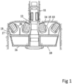
- Figure 1 shows how a pilot hole 11, which is pre-drilled in known way, between an upper and lower level (not shown).
- a drill head 10 is connected to drive stem 12, then the drill head 10 is rotated and pressed against the ring-shaped surface 13 that surrounds the pilot hole 11.
- the drill head 10 comprises a body 16 and a plurality of roller cutters 14 which are rotatably mounted on the body 16 using saddles 15 (otherwise known as fasteners).
- the saddles 15 are mounted on the body 16.
- the drive stem 12 is connected to the body 16.
- the body 16 has a mounting surface 17 on which the saddles are carried.
- each roller cutter 14 comprises circumferal row of buttons or cutting members 25 of cemented carbide that are mounted in a known way.
- the saddle 15 comprises a bottom surface 18, which is intended to be connected, for instance by bolting or welding, to the mounting surface 17 of the body 16.
- the saddle 15 also comprises two saddle cutter seats 19, 20 between which the roller cutter 14 is mounted.
- the saddle cutter seats, 19, 20, are, at the ends thereof facing away from the bottom surface 18 formed with arms 21.
- the arms 21 have different lengths from the bottom surface 18.
- Fastening devices in the form of threaded bolts 22 and nuts 23 are intended to hold the roller cutter 14 and saddle 15 together.
- Figure 3 shows a cross section of the roller cutter 14 having a shaft 33 with a longitudinal centre line 40.
- Directions in this description refer to the centre line 40.
- Axially refers to a direction along the centre line 40 illustrated by a first arrow 42 and radially refers to a direction along the radius of the cross section of the roller cutter 14, illustrated by a second arrow 44.
- the ends of the shaft 33 along the longitudinal centre line 40 have a machined square, which is intended to abut against a support surface (not shown) in the arms 21 of the saddle 15.
- a hub 24 (otherwise known as a cutter shell) is rotatably mounted on the shaft 33 via bearing members 26, 28.
- the bearing members 26, 28 are received in circumferal grooves in a hub 24.
- the hub 24 is locked axially in relation to the shaft 33.
- the bearing members 26 are received in a circumferential groove in the hub 24.
- the hub 24 is locked axially in relation to the shaft by means of a locking member 28, preferably in the form of balls, which co-operate with circumferential grooves in both the shaft 33 and the hub 24.
- a seal retainer 46 Between the axial ends of the hub 24 and the shaft 33 of the roller cutter 14 at least at one end, preferably both, there is a seal retainer 46.
- Figure 4 shows an enlargement of the roller cutter 14 in the location of the seal retainer 46.
- Figure 5a shows an enlargement of the roller cutter 14 in the location of the seal retainer 46 before the secondary cutter seal 62 is installed.
- Figure 5b shows an enlargement of the secondary cutter seal 62 before being installed onto the seal retainer 46.
- the seal retainer 46 are typically equipped with relief holes having plugs mounted in said holes to prevent lubricant from leaking out through said holes (not shown) and are typically made from mild steel.
- the seal retainer 46 supports a primary cutter seal 48.
- the primary cutter seal 48 typically comprises two O-rings 50 made of a resilient material and two seal rings 52 made of cast iron.
- the primary cutter seal 48 creates a seal between the hub 24 and the shaft 33 in both axial and radial directions.
- the primary cutter seal 48 is intended to prevent drill cuttings and other impurities from entering into the roller cutter 14 and the bearing system and to prevent leakage of the lubricants from the roller cutter 14.
- the seal retainer 46 has a radially upward projecting region 54 having an axially outermost end 56 and an axially inner most end 58.
- the radially upward projecting region 54 is stepped such that the axially outermost end 56 projects radially upwards to a larger extent than the axially inner most end 58 therefore forming a stepped region 60.
- the axially outermost end 56 is located axially and radially further from the primary cutter seal 48 compared to the axially inner most end 58.
- the axially innermost end 58 of the axially upward projecting region 54 of the seal retainer 46 accommodates a secondary cutter seal 62.
- the secondary cutter seal 62 protects the primary cutter seal 48.
- the secondary cutter seal 62 must be capable of forming an axial seal between seal retainer 46 and the hub 24 using a small contact area relative to the size of the seal.
- the secondary cutter seal 62 could for example be in the form of a v-ring, wiper seal, lip seal or any other seal that is able to create a seal against the rotating surface of the hub 24 using only a small contact area relative to the size of the seal.
- the secondary cutter seal 62 is accommodated in the stepped region 60 of the seal retainer 46, such that a first surface 64 of the secondary cutter seal 62 is supported by the upper surface 66 of the axially innermost end 58 of the seal retainer 46 and a second surface 68 of the secondary cutter seal 62 is supported by a side surface 70 of the axially outermost end 56 of the seal retainer 46.
- the secondary cutter seal 62 also has a flexible lip 72 which presses towards and then slides against a supporting face 74 of the hub 24 forming a seal in an axial direction.
- the secondary cutter seal 62 sits stationary on the seal retainer 46.
- the secondary cutter seal 62 is made of a resilient material that is resistant to heat and wear e.g. rubber.
- the secondary cutter seal 62 is held in place by pre-tension, glue or clamp.
- the secondary cutter seal 62 is held in place by radial pre-tension alone by the seal retainer 46 being dimensioned slightly larger than the secondary cutter seal 62, so that it is fitted in place by being stretched onto the seal retainer 42.
- the distance (D) between the supporting face 74 of the hub 24 and the side surface 70 of the axially outermost end 56 of seal retainer 46 is slightly less than the width (W) of the secondary cutter seal 62 before being installed onto the seal retainer 46, so that when the secondary cutter seal 62 is inserted it compresses to ensure constant sealing against the supporting face 74.
- the secondary cutter seal 62 forms a seal between the seal retainer 46 and the hub 24 in an axial direction and is intended to protect the primary cutter seal 48 from wear and damage.
- Figure 6 shows that there is a groove 76 in the side surface 70 of the seal retainer 46 in which the secondary cutter seal 62 is positioned inside.
- the secondary cutter seal 62 abuts the outer diameter 78 of the groove 76, the upper surface 66 of the axially innermost end 58 of the seal retainer 46.
Landscapes
- Engineering & Computer Science (AREA)
- Geology (AREA)
- Life Sciences & Earth Sciences (AREA)
- Mining & Mineral Resources (AREA)
- Physics & Mathematics (AREA)
- Environmental & Geological Engineering (AREA)
- Fluid Mechanics (AREA)
- Mechanical Engineering (AREA)
- General Life Sciences & Earth Sciences (AREA)
- Geochemistry & Mineralogy (AREA)
- Earth Drilling (AREA)
- Sealing Devices (AREA)
- Processing And Handling Of Plastics And Other Materials For Molding In General (AREA)
Claims (7)
- Outil de coupe à rouleaux (14) pour une tête de forage (10) pour un forage en montant ;ledit outil de coupe à rouleaux présentant un arbre (33) avec une ligne médiane longitudinale (40) ;un moyeu (24) monté rotatif sur l'arbre (33) ;un dispositif de retenue de joint (46) situé entre les extrémités axiales du moyeu (24) et de l'arbre (33), agencé au moins à une extrémité de l'outil de coupe à rouleaux(14) ;le dispositif de retenue de joint (46) supportant un joint principal d'outil de coupe (48) assurant l'étanchéité entre l'arbre (33) et le moyeu (24) à la fois dans la direction axiale et la direction radiale ;dans lequelun joint secondaire d'outil de coupe (62) est situé entre le dispositif de retenue de joint (46) et le moyeu (24), et le joint secondaire d'outil de coupe (62) assure l'étanchéité dans la direction axiale ;dans lequel une première surface (64) du joint secondaire d'outil de coupe (62) est supportée par la surface supérieure (66) de l'extrémité axialement la plus intérieure (58) du dispositif de retenue de joint (46) et une seconde surface (68) du joint secondaire d'outil de coupe (62) est supportée par une surface latérale (70) de la partie radialement la plus extérieure du dispositif de retenue de joint (46) et dans lequel le joint secondaire d'outil de coupe (62) comprend une lèvre souple (72) qui appuie contre une face porteuse (74) du moyeu (24) assurant l'étanchéité dans une direction axiale ;caractérisé en ce que la surface latérale (70) de la partie radialement la plus extérieure du dispositif de retenue de joint (46) comprend une rainure (76).
- Outil de coupe à rouleaux (14) selon la revendication 1, dans lequel le dispositif de retenue de joint (46) comprend une région saillante radialement vers le haut (54) présentant une extrémité axialement la plus extérieure (56) et une extrémité axialement la plus intérieure (58) et dans lequel la région saillante radialement vers le haut (54) est étagée de telle sorte que l'extrémité axialement la plus extérieure (56) fasse saillie radialement vers le haut dans une plus grande mesure que l'extrémité axialement la plus intérieure (58).
- Outil de coupe à rouleaux (14) selon l'une quelconque des revendications précédentes, dans lequel le joint secondaire d'outil de coupe (62) est composé d'un matériau élastique.
- Outil de coupe à rouleaux (14) selon l'une quelconque des revendications précédentes, dans lequel le joint secondaire d'outil de coupe (62) est un joint annulaire en V, racleur ou à lèvre.
- Outil de coupe à rouleaux (14) selon l'une quelconque des revendications précédentes, dans lequel une distance (D) entre la face de support (74) du moyeu (24) et la surface latérale (70) de l'extrémité axialement la plus extérieure (56) du dispositif de retenue de joint (46) est inférieure à une largeur (W) du joint secondaire d'outil de coupe (62) avant une installation sur l'outil de coupe à rouleaux (14).
- Outil de coupe à rouleaux (14) selon l'une quelconque des revendications précédentes, dans lequel le joint secondaire d'outil de coupe (62) est maintenu en place par pré-tension, de la colle ou serrage.
- Outil de coupe à rouleaux (14) selon l'une quelconque des revendications précédentes, dans lequel le joint secondaire d'outil de coupe (62) et le dispositif de retenue de joint (46) sont fixes.
Priority Applications (9)
| Application Number | Priority Date | Filing Date | Title |
|---|---|---|---|
| EP20158642.7A EP3868997B1 (fr) | 2020-02-21 | 2020-02-21 | Outil de coupe à rouleaux présentant une étanchéité améliorée |
| ES20158642T ES2996348T3 (en) | 2020-02-21 | 2020-02-21 | Roller cutting tool with improved sealing |
| CN202180014875.5A CN115087791B (zh) | 2020-02-21 | 2021-02-17 | 具有改进的密封的滚刀式切削刀具 |
| CA3167903A CA3167903A1 (fr) | 2020-02-21 | 2021-02-17 | Outil de coupe a molettes a etancheite amelioree |
| AU2021223577A AU2021223577B9 (en) | 2020-02-21 | 2021-02-17 | Roller cutting tool with improved sealing |
| PE2022001536A PE20221735A1 (es) | 2020-02-21 | 2021-02-17 | Herramienta de corte de rodillos con sellado mejorado |
| US17/800,960 US12024951B2 (en) | 2020-02-21 | 2021-02-17 | Roller cutting tool with improved sealing |
| PCT/EP2021/053893 WO2021165323A1 (fr) | 2020-02-21 | 2021-02-17 | Outil de coupe à molettes à étanchéité améliorée |
| ZA2022/08469A ZA202208469B (en) | 2020-02-21 | 2022-07-28 | Roller cutting tool with improved sealing |
Applications Claiming Priority (1)
| Application Number | Priority Date | Filing Date | Title |
|---|---|---|---|
| EP20158642.7A EP3868997B1 (fr) | 2020-02-21 | 2020-02-21 | Outil de coupe à rouleaux présentant une étanchéité améliorée |
Publications (3)
| Publication Number | Publication Date |
|---|---|
| EP3868997A1 EP3868997A1 (fr) | 2021-08-25 |
| EP3868997B1 true EP3868997B1 (fr) | 2024-11-20 |
| EP3868997C0 EP3868997C0 (fr) | 2024-11-20 |
Family
ID=69723832
Family Applications (1)
| Application Number | Title | Priority Date | Filing Date |
|---|---|---|---|
| EP20158642.7A Active EP3868997B1 (fr) | 2020-02-21 | 2020-02-21 | Outil de coupe à rouleaux présentant une étanchéité améliorée |
Country Status (9)
| Country | Link |
|---|---|
| US (1) | US12024951B2 (fr) |
| EP (1) | EP3868997B1 (fr) |
| CN (1) | CN115087791B (fr) |
| AU (1) | AU2021223577B9 (fr) |
| CA (1) | CA3167903A1 (fr) |
| ES (1) | ES2996348T3 (fr) |
| PE (1) | PE20221735A1 (fr) |
| WO (1) | WO2021165323A1 (fr) |
| ZA (1) | ZA202208469B (fr) |
Families Citing this family (2)
| Publication number | Priority date | Publication date | Assignee | Title |
|---|---|---|---|---|
| EP4343109B1 (fr) * | 2022-09-21 | 2025-04-02 | Sandvik Mining and Construction Tools AB | Outil de forage montant avec étiquette d'identification numérique |
| CN116357332B (zh) * | 2023-03-29 | 2026-02-17 | 中南大学 | 一种多层可升降式锥形正反钻进装备及施工方法 |
Citations (1)
| Publication number | Priority date | Publication date | Assignee | Title |
|---|---|---|---|---|
| US4509607A (en) * | 1983-08-26 | 1985-04-09 | Dresser Industries, Inc. | Compressible pressure compensator within closed lubricant volume of an earth boring apparatus |
Family Cites Families (7)
| Publication number | Priority date | Publication date | Assignee | Title |
|---|---|---|---|---|
| US3303898A (en) * | 1962-11-09 | 1967-02-14 | Mini Petrolului | Bearing sealing and lubricating device |
| US3572452A (en) * | 1969-04-16 | 1971-03-30 | Dougles F Winberg | Rolling cutter and seals therefor |
| US6196339B1 (en) * | 1995-12-19 | 2001-03-06 | Smith International, Inc. | Dual-seal drill bit pressure communication system |
| US5842700A (en) * | 1996-10-08 | 1998-12-01 | Smith International, Inc. | Composite rock bit seal |
| SE525429C2 (sv) * | 2003-01-30 | 2005-02-22 | Sandvik Ab | Skärrulle till ett borrhuvud för roterande borrning |
| EP2781684A1 (fr) | 2013-03-20 | 2014-09-24 | Sandvik Intellectual Property AB | Trépan à molettes avec étanchéité améliorée |
| US10458187B2 (en) * | 2015-02-27 | 2019-10-29 | Baker Hughes, A Ge Company, Llc | Seal assemblies for earth-boring tools, earth-boring tools so equipped, and related methods |
-
2020
- 2020-02-21 ES ES20158642T patent/ES2996348T3/es active Active
- 2020-02-21 EP EP20158642.7A patent/EP3868997B1/fr active Active
-
2021
- 2021-02-17 CA CA3167903A patent/CA3167903A1/fr active Pending
- 2021-02-17 US US17/800,960 patent/US12024951B2/en active Active
- 2021-02-17 PE PE2022001536A patent/PE20221735A1/es unknown
- 2021-02-17 AU AU2021223577A patent/AU2021223577B9/en active Active
- 2021-02-17 WO PCT/EP2021/053893 patent/WO2021165323A1/fr not_active Ceased
- 2021-02-17 CN CN202180014875.5A patent/CN115087791B/zh active Active
-
2022
- 2022-07-28 ZA ZA2022/08469A patent/ZA202208469B/en unknown
Patent Citations (1)
| Publication number | Priority date | Publication date | Assignee | Title |
|---|---|---|---|---|
| US4509607A (en) * | 1983-08-26 | 1985-04-09 | Dresser Industries, Inc. | Compressible pressure compensator within closed lubricant volume of an earth boring apparatus |
Also Published As
| Publication number | Publication date |
|---|---|
| CN115087791B (zh) | 2025-08-19 |
| EP3868997A1 (fr) | 2021-08-25 |
| ZA202208469B (en) | 2025-01-29 |
| CN115087791A (zh) | 2022-09-20 |
| AU2021223577A1 (en) | 2022-09-08 |
| EP3868997C0 (fr) | 2024-11-20 |
| AU2021223577B9 (en) | 2026-03-05 |
| US20230072404A1 (en) | 2023-03-09 |
| US12024951B2 (en) | 2024-07-02 |
| WO2021165323A1 (fr) | 2021-08-26 |
| AU2021223577B2 (en) | 2026-01-22 |
| CA3167903A1 (fr) | 2021-08-26 |
| ES2996348T3 (en) | 2025-02-12 |
| PE20221735A1 (es) | 2022-11-07 |
Similar Documents
| Publication | Publication Date | Title |
|---|---|---|
| US3216513A (en) | Cutter assemblies for rock drilling | |
| US7997659B2 (en) | Rotary cutter for tunnel boring machine | |
| US6026917A (en) | Earth-boring bit with improved bearing seal | |
| US2243340A (en) | Rotary blowout preventer | |
| US7461708B2 (en) | Elastomeric seal assembly having auxiliary annular seal components | |
| US7347290B2 (en) | Multi-part energizer for mechanical seal assembly | |
| US12024951B2 (en) | Roller cutting tool with improved sealing | |
| US4722404A (en) | Drill bit bearing seal | |
| CA1333484C (fr) | Joint en elastomere favorisant la resistance a l'usure d'un outil de forage | |
| US4167980A (en) | Rock boring cutter with replaceable cutting element | |
| EP0415519B1 (fr) | Système d'étanchéité double pour trépan de forage rotatif | |
| EP3262268B1 (fr) | Ensembles d'étanchéité de trépans de forage, trépans ainsi équipés et procédés associés | |
| US4193464A (en) | Replaceable shirttail | |
| US4738323A (en) | Thrust bearing and cone locking assembly for rock drill bit | |
| WO2008006146A1 (fr) | Alésoir à cylindre | |
| CN110905916A (zh) | 旋转导向及垂钻工具用pdc轴承 | |
| RU2465428C1 (ru) | Герметизированная опора шарошечного долота | |
| CN212428833U (zh) | 一种泥水平衡顶管机头刀盘结构 | |
| WO1998013573A1 (fr) | Outils de coupe de roche rotatifs a axe incline munis d'anneaux de coupe faciles a remplacer |
Legal Events
| Date | Code | Title | Description |
|---|---|---|---|
| PUAI | Public reference made under article 153(3) epc to a published international application that has entered the european phase |
Free format text: ORIGINAL CODE: 0009012 |
|
| STAA | Information on the status of an ep patent application or granted ep patent |
Free format text: STATUS: THE APPLICATION HAS BEEN PUBLISHED |
|
| AK | Designated contracting states |
Kind code of ref document: A1 Designated state(s): AL AT BE BG CH CY CZ DE DK EE ES FI FR GB GR HR HU IE IS IT LI LT LU LV MC MK MT NL NO PL PT RO RS SE SI SK SM TR |
|
| STAA | Information on the status of an ep patent application or granted ep patent |
Free format text: STATUS: REQUEST FOR EXAMINATION WAS MADE |
|
| 17P | Request for examination filed |
Effective date: 20220225 |
|
| RBV | Designated contracting states (corrected) |
Designated state(s): AL AT BE BG CH CY CZ DE DK EE ES FI FR GB GR HR HU IE IS IT LI LT LU LV MC MK MT NL NO PL PT RO RS SE SI SK SM TR |
|
| STAA | Information on the status of an ep patent application or granted ep patent |
Free format text: STATUS: EXAMINATION IS IN PROGRESS |
|
| 17Q | First examination report despatched |
Effective date: 20230327 |
|
| GRAP | Despatch of communication of intention to grant a patent |
Free format text: ORIGINAL CODE: EPIDOSNIGR1 |
|
| STAA | Information on the status of an ep patent application or granted ep patent |
Free format text: STATUS: GRANT OF PATENT IS INTENDED |
|
| INTG | Intention to grant announced |
Effective date: 20240619 |
|
| RIN1 | Information on inventor provided before grant (corrected) |
Inventor name: LINDBLOM, ANDERS Inventor name: LOIKKANEN, JOONA |
|
| GRAS | Grant fee paid |
Free format text: ORIGINAL CODE: EPIDOSNIGR3 |
|
| GRAA | (expected) grant |
Free format text: ORIGINAL CODE: 0009210 |
|
| STAA | Information on the status of an ep patent application or granted ep patent |
Free format text: STATUS: THE PATENT HAS BEEN GRANTED |
|
| RAP3 | Party data changed (applicant data changed or rights of an application transferred) |
Owner name: SANDVIK MINING AND CONSTRUCTION TOOLS AB |
|
| AK | Designated contracting states |
Kind code of ref document: B1 Designated state(s): AL AT BE BG CH CY CZ DE DK EE ES FI FR GB GR HR HU IE IS IT LI LT LU LV MC MK MT NL NO PL PT RO RS SE SI SK SM TR |
|
| REG | Reference to a national code |
Ref country code: GB Ref legal event code: FG4D |
|
| REG | Reference to a national code |
Ref country code: CH Ref legal event code: EP |
|
| REG | Reference to a national code |
Ref country code: DE Ref legal event code: R096 Ref document number: 602020041532 Country of ref document: DE |
|
| REG | Reference to a national code |
Ref country code: IE Ref legal event code: FG4D |
|
| U01 | Request for unitary effect filed |
Effective date: 20241209 |
|
| U07 | Unitary effect registered |
Designated state(s): AT BE BG DE DK EE FI FR IT LT LU LV MT NL PT RO SE SI Effective date: 20241219 |
|
| REG | Reference to a national code |
Ref country code: ES Ref legal event code: FG2A Ref document number: 2996348 Country of ref document: ES Kind code of ref document: T3 Effective date: 20250212 |
|
| PG25 | Lapsed in a contracting state [announced via postgrant information from national office to epo] |
Ref country code: HR Free format text: LAPSE BECAUSE OF FAILURE TO SUBMIT A TRANSLATION OF THE DESCRIPTION OR TO PAY THE FEE WITHIN THE PRESCRIBED TIME-LIMIT Effective date: 20241120 Ref country code: IS Free format text: LAPSE BECAUSE OF FAILURE TO SUBMIT A TRANSLATION OF THE DESCRIPTION OR TO PAY THE FEE WITHIN THE PRESCRIBED TIME-LIMIT Effective date: 20250320 |
|
| U20 | Renewal fee for the european patent with unitary effect paid |
Year of fee payment: 6 Effective date: 20250319 |
|
| PG25 | Lapsed in a contracting state [announced via postgrant information from national office to epo] |
Ref country code: GR Free format text: LAPSE BECAUSE OF FAILURE TO SUBMIT A TRANSLATION OF THE DESCRIPTION OR TO PAY THE FEE WITHIN THE PRESCRIBED TIME-LIMIT Effective date: 20250221 |
|
| PG25 | Lapsed in a contracting state [announced via postgrant information from national office to epo] |
Ref country code: PL Free format text: LAPSE BECAUSE OF FAILURE TO SUBMIT A TRANSLATION OF THE DESCRIPTION OR TO PAY THE FEE WITHIN THE PRESCRIBED TIME-LIMIT Effective date: 20241120 |
|
| PG25 | Lapsed in a contracting state [announced via postgrant information from national office to epo] |
Ref country code: RS Free format text: LAPSE BECAUSE OF FAILURE TO SUBMIT A TRANSLATION OF THE DESCRIPTION OR TO PAY THE FEE WITHIN THE PRESCRIBED TIME-LIMIT Effective date: 20250220 |
|
| PG25 | Lapsed in a contracting state [announced via postgrant information from national office to epo] |
Ref country code: SM Free format text: LAPSE BECAUSE OF FAILURE TO SUBMIT A TRANSLATION OF THE DESCRIPTION OR TO PAY THE FEE WITHIN THE PRESCRIBED TIME-LIMIT Effective date: 20241120 |
|
| PG25 | Lapsed in a contracting state [announced via postgrant information from national office to epo] |
Ref country code: SK Free format text: LAPSE BECAUSE OF FAILURE TO SUBMIT A TRANSLATION OF THE DESCRIPTION OR TO PAY THE FEE WITHIN THE PRESCRIBED TIME-LIMIT Effective date: 20241120 |
|
| PG25 | Lapsed in a contracting state [announced via postgrant information from national office to epo] |
Ref country code: CZ Free format text: LAPSE BECAUSE OF FAILURE TO SUBMIT A TRANSLATION OF THE DESCRIPTION OR TO PAY THE FEE WITHIN THE PRESCRIBED TIME-LIMIT Effective date: 20241120 |
|
| PG25 | Lapsed in a contracting state [announced via postgrant information from national office to epo] |
Ref country code: MC Free format text: LAPSE BECAUSE OF FAILURE TO SUBMIT A TRANSLATION OF THE DESCRIPTION OR TO PAY THE FEE WITHIN THE PRESCRIBED TIME-LIMIT Effective date: 20241120 |
|
| PLBE | No opposition filed within time limit |
Free format text: ORIGINAL CODE: 0009261 |
|
| STAA | Information on the status of an ep patent application or granted ep patent |
Free format text: STATUS: NO OPPOSITION FILED WITHIN TIME LIMIT |
|
| REG | Reference to a national code |
Ref country code: CH Ref legal event code: PL |
|
| PG25 | Lapsed in a contracting state [announced via postgrant information from national office to epo] |
Ref country code: CH Free format text: LAPSE BECAUSE OF NON-PAYMENT OF DUE FEES Effective date: 20250228 |
|
| 26N | No opposition filed |
Effective date: 20250821 |
|
| GBPC | Gb: european patent ceased through non-payment of renewal fee |
Effective date: 20250221 |
|
| PG25 | Lapsed in a contracting state [announced via postgrant information from national office to epo] |
Ref country code: GB Free format text: LAPSE BECAUSE OF NON-PAYMENT OF DUE FEES Effective date: 20250221 |
|
| PG25 | Lapsed in a contracting state [announced via postgrant information from national office to epo] |
Ref country code: IE Free format text: LAPSE BECAUSE OF NON-PAYMENT OF DUE FEES Effective date: 20250221 |
|
| U20 | Renewal fee for the european patent with unitary effect paid |
Year of fee payment: 7 Effective date: 20260302 |
|
| PGFP | Annual fee paid to national office [announced via postgrant information from national office to epo] |
Ref country code: ES Payment date: 20260305 Year of fee payment: 7 |
|
| PGFP | Annual fee paid to national office [announced via postgrant information from national office to epo] |
Ref country code: NO Payment date: 20260211 Year of fee payment: 7 |