EP3869006B1 - Rotorscheibe mit integralem bohrungskorb - Google Patents
Rotorscheibe mit integralem bohrungskorb Download PDFInfo
- Publication number
- EP3869006B1 EP3869006B1 EP20216101.4A EP20216101A EP3869006B1 EP 3869006 B1 EP3869006 B1 EP 3869006B1 EP 20216101 A EP20216101 A EP 20216101A EP 3869006 B1 EP3869006 B1 EP 3869006B1
- Authority
- EP
- European Patent Office
- Prior art keywords
- rotor
- bore
- section
- panel
- basket
- Prior art date
- Legal status (The legal status is an assumption and is not a legal conclusion. Google has not performed a legal analysis and makes no representation as to the accuracy of the status listed.)
- Active
Links
Images



Classifications
-
- F—MECHANICAL ENGINEERING; LIGHTING; HEATING; WEAPONS; BLASTING
- F04—POSITIVE - DISPLACEMENT MACHINES FOR LIQUIDS; PUMPS FOR LIQUIDS OR ELASTIC FLUIDS
- F04D—NON-POSITIVE-DISPLACEMENT PUMPS
- F04D29/00—Details, component parts, or accessories
- F04D29/04—Shafts or bearings, or assemblies thereof
-
- F—MECHANICAL ENGINEERING; LIGHTING; HEATING; WEAPONS; BLASTING
- F01—MACHINES OR ENGINES IN GENERAL; ENGINE PLANTS IN GENERAL; STEAM ENGINES
- F01D—NON-POSITIVE DISPLACEMENT MACHINES OR ENGINES, e.g. STEAM TURBINES
- F01D5/00—Blades; Blade-carrying members; Heating, heat-insulating, cooling or antivibration means on the blades or the members
- F01D5/02—Blade-carrying members, e.g. rotors
- F01D5/08—Heating, heat-insulating or cooling means
- F01D5/081—Cooling fluid being directed on the side of the rotor disc or at the roots of the blades
- F01D5/084—Cooling fluid being directed on the side of the rotor disc or at the roots of the blades the fluid circulating at the periphery of a multistage rotor, e.g. of drum type
-
- F—MECHANICAL ENGINEERING; LIGHTING; HEATING; WEAPONS; BLASTING
- F01—MACHINES OR ENGINES IN GENERAL; ENGINE PLANTS IN GENERAL; STEAM ENGINES
- F01D—NON-POSITIVE DISPLACEMENT MACHINES OR ENGINES, e.g. STEAM TURBINES
- F01D25/00—Component parts, details, or accessories, not provided for in, or of interest apart from, other groups
- F01D25/08—Cooling; Heating; Heat-insulation
- F01D25/14—Casings modified therefor
- F01D25/145—Thermally insulated casings
-
- F—MECHANICAL ENGINEERING; LIGHTING; HEATING; WEAPONS; BLASTING
- F02—COMBUSTION ENGINES; HOT-GAS OR COMBUSTION-PRODUCT ENGINE PLANTS
- F02C—GAS-TURBINE PLANTS; AIR INTAKES FOR JET-PROPULSION PLANTS; CONTROLLING FUEL SUPPLY IN AIR-BREATHING JET-PROPULSION PLANTS
- F02C7/00—Features, components parts, details or accessories, not provided for in, or of interest apart form groups F02C1/00 - F02C6/00; Air intakes for jet-propulsion plants
- F02C7/12—Cooling of plants
- F02C7/16—Cooling of plants characterised by cooling medium
- F02C7/18—Cooling of plants characterised by cooling medium the medium being gaseous, e.g. air
- F02C7/185—Cooling means for reducing the temperature of the cooling air or gas
-
- F—MECHANICAL ENGINEERING; LIGHTING; HEATING; WEAPONS; BLASTING
- F04—POSITIVE - DISPLACEMENT MACHINES FOR LIQUIDS; PUMPS FOR LIQUIDS OR ELASTIC FLUIDS
- F04D—NON-POSITIVE-DISPLACEMENT PUMPS
- F04D19/00—Axial-flow pumps
- F04D19/02—Multi-stage pumps
-
- F—MECHANICAL ENGINEERING; LIGHTING; HEATING; WEAPONS; BLASTING
- F04—POSITIVE - DISPLACEMENT MACHINES FOR LIQUIDS; PUMPS FOR LIQUIDS OR ELASTIC FLUIDS
- F04D—NON-POSITIVE-DISPLACEMENT PUMPS
- F04D27/00—Control, e.g. regulation, of pumps, pumping installations or pumping systems specially adapted for elastic fluids
- F04D27/009—Control, e.g. regulation, of pumps, pumping installations or pumping systems specially adapted for elastic fluids by bleeding, by passing or recycling fluid
-
- F—MECHANICAL ENGINEERING; LIGHTING; HEATING; WEAPONS; BLASTING
- F04—POSITIVE - DISPLACEMENT MACHINES FOR LIQUIDS; PUMPS FOR LIQUIDS OR ELASTIC FLUIDS
- F04D—NON-POSITIVE-DISPLACEMENT PUMPS
- F04D29/00—Details, component parts, or accessories
- F04D29/05—Shafts or bearings, or assemblies thereof, specially adapted for elastic fluid pumps
- F04D29/053—Shafts
-
- F—MECHANICAL ENGINEERING; LIGHTING; HEATING; WEAPONS; BLASTING
- F04—POSITIVE - DISPLACEMENT MACHINES FOR LIQUIDS; PUMPS FOR LIQUIDS OR ELASTIC FLUIDS
- F04D—NON-POSITIVE-DISPLACEMENT PUMPS
- F04D29/00—Details, component parts, or accessories
- F04D29/58—Cooling; Heating; Diminishing heat transfer
- F04D29/582—Cooling; Heating; Diminishing heat transfer specially adapted for elastic fluid pumps
- F04D29/584—Cooling; Heating; Diminishing heat transfer specially adapted for elastic fluid pumps cooling or heating the machine
-
- F—MECHANICAL ENGINEERING; LIGHTING; HEATING; WEAPONS; BLASTING
- F05—INDEXING SCHEMES RELATING TO ENGINES OR PUMPS IN VARIOUS SUBCLASSES OF CLASSES F01-F04
- F05D—INDEXING SCHEME FOR ASPECTS RELATING TO NON-POSITIVE-DISPLACEMENT MACHINES OR ENGINES, GAS-TURBINES OR JET-PROPULSION PLANTS
- F05D2220/00—Application
- F05D2220/30—Application in turbines
- F05D2220/32—Application in turbines in gas turbines
- F05D2220/321—Application in turbines in gas turbines for a special turbine stage
- F05D2220/3216—Application in turbines in gas turbines for a special turbine stage for a special compressor stage
-
- F—MECHANICAL ENGINEERING; LIGHTING; HEATING; WEAPONS; BLASTING
- F05—INDEXING SCHEMES RELATING TO ENGINES OR PUMPS IN VARIOUS SUBCLASSES OF CLASSES F01-F04
- F05D—INDEXING SCHEME FOR ASPECTS RELATING TO NON-POSITIVE-DISPLACEMENT MACHINES OR ENGINES, GAS-TURBINES OR JET-PROPULSION PLANTS
- F05D2230/00—Manufacture
- F05D2230/20—Manufacture essentially without removing material
- F05D2230/23—Manufacture essentially without removing material by permanently joining parts together
- F05D2230/232—Manufacture essentially without removing material by permanently joining parts together by welding
-
- F—MECHANICAL ENGINEERING; LIGHTING; HEATING; WEAPONS; BLASTING
- F05—INDEXING SCHEMES RELATING TO ENGINES OR PUMPS IN VARIOUS SUBCLASSES OF CLASSES F01-F04
- F05D—INDEXING SCHEME FOR ASPECTS RELATING TO NON-POSITIVE-DISPLACEMENT MACHINES OR ENGINES, GAS-TURBINES OR JET-PROPULSION PLANTS
- F05D2230/00—Manufacture
- F05D2230/60—Assembly methods
- F05D2230/64—Assembly methods using positioning or alignment devices for aligning or centring, e.g. pins
- F05D2230/642—Assembly methods using positioning or alignment devices for aligning or centring, e.g. pins using maintaining alignment while permitting differential dilatation
-
- F—MECHANICAL ENGINEERING; LIGHTING; HEATING; WEAPONS; BLASTING
- F05—INDEXING SCHEMES RELATING TO ENGINES OR PUMPS IN VARIOUS SUBCLASSES OF CLASSES F01-F04
- F05D—INDEXING SCHEME FOR ASPECTS RELATING TO NON-POSITIVE-DISPLACEMENT MACHINES OR ENGINES, GAS-TURBINES OR JET-PROPULSION PLANTS
- F05D2240/00—Components
- F05D2240/60—Shafts
- F05D2240/61—Hollow
-
- F—MECHANICAL ENGINEERING; LIGHTING; HEATING; WEAPONS; BLASTING
- F05—INDEXING SCHEMES RELATING TO ENGINES OR PUMPS IN VARIOUS SUBCLASSES OF CLASSES F01-F04
- F05D—INDEXING SCHEME FOR ASPECTS RELATING TO NON-POSITIVE-DISPLACEMENT MACHINES OR ENGINES, GAS-TURBINES OR JET-PROPULSION PLANTS
- F05D2260/00—Function
- F05D2260/94—Functionality given by mechanical stress related aspects such as low cycle fatigue [LCF] of high cycle fatigue [HCF]
- F05D2260/941—Functionality given by mechanical stress related aspects such as low cycle fatigue [LCF] of high cycle fatigue [HCF] particularly aimed at mechanical or thermal stress reduction
-
- Y—GENERAL TAGGING OF NEW TECHNOLOGICAL DEVELOPMENTS; GENERAL TAGGING OF CROSS-SECTIONAL TECHNOLOGIES SPANNING OVER SEVERAL SECTIONS OF THE IPC; TECHNICAL SUBJECTS COVERED BY FORMER USPC CROSS-REFERENCE ART COLLECTIONS [XRACs] AND DIGESTS
- Y02—TECHNOLOGIES OR APPLICATIONS FOR MITIGATION OR ADAPTATION AGAINST CLIMATE CHANGE
- Y02T—CLIMATE CHANGE MITIGATION TECHNOLOGIES RELATED TO TRANSPORTATION
- Y02T50/00—Aeronautics or air transport
- Y02T50/60—Efficient propulsion technologies, e.g. for aircraft
Definitions
- the present invention relates to gas turbine engines in general, and to a rotor section for a gas turbine engine with a bore basket in particular.
- Gas turbine engines typically include a compressor section, a combustor section, and a turbine section. Some gas turbine engines typically include a fan section disposed axially forward of the combustor section. One or more shafts connect compressor stages to turbine stages. The compressor section and the turbine section each include multiple rotor stages arranged sequentially along a fluid flow path. Each rotor stage includes a rotor bore protruding radially inward toward the shafts. High temperature air in communication with a rotor bore can cause the rotor bore to experience thermal expansion. To control such thermal expansion, gas turbine engine are known to dispose a bore basket between one or more rotor bores and the shafts to mechanically separate the rotor bores from hot air flow adjacent the shafts. The bore basket functions as both as a heat shield and as a flow guide.
- Bore baskets are typically configured as a cylindrical structure that includes a radially inner tube displaced from a radially outer tube to define an interior annular region there between for the passage of gas.
- Existing bore baskets are formed from a plurality of elements that collectively form the bore basket. Those elements must be manufactured to tight tolerances and assembled to one another to create the interior annular region and requisite sealing between elements. For example, in some instances the outer radial tube must be thermally expanded to permit receipt of the inner tube. Once the outer radial tube is cooled (e.g., to the temperature of the inner radial tube), the inner and outer radial tubes are mechanically connected. Such techniques can cause the assembly process to be time consuming and expensive.
- the elements themselves will often be subject to different degrees of thermal expansion; e.g., because of different physical configuration, different materials, and/or their position in the engine and consequent thermal exposure.
- the different elements "fitted together” must allow for different relative amounts of thermal expansion.
- the mechanical features that maintain the bore basket elements together (anti-rotation keys, snaps, etc.), but still allow for thermal expansion, can produce wear points that limit the life of the bore basket.
- EP 2910735 A1 discloses a prior art gas turbine engine rotor section according to the preamble of claim 1.
- a gas turbine engine rotor section is provided as set forth in claim 1.
- the plurality of inlet apertures may extend through the outer radial panel at the first axial position.
- the plurality of exit apertures may extend through the outer radial panel at the second axial position.
- the plurality of inlet apertures and the plurality of exit apertures may be circumferentially disposed around the outer radial panel.
- the inner radial panel and the outer radial panel may be welded to one another, and the bore basket and the rotor bore may be welded to one another.
- a gas turbine engine rotor section is provided as set forth in claim 3.
- the sub-section may include at least two said rotor bores.
- the hub structure may include a plurality of HS inlet apertures and a plurality of HS exit apertures, and the plurality of HS inlet apertures and the plurality of HS exit apertures are in fluid communication with the sub-section of the bore cavity.
- the sub-section may be located at a forward portion of the bore cavity.
- the sub-section may be located at an aft portion of the bore cavity.
- the rotor section may further include a second bore basket having a second engagement panel, a second cylindrical inner radial panel, and a second cylindrical outer radial panel.
- the second inner and outer radial panels extend axially.
- the second inner radial panel is disposed radially inside of and separated from the second outer radial panel.
- a second annular passage is disposed between the second inner and outer radial panels.
- the second bore basket includes a plurality of second inlet apertures in fluid communication with the second annular passage.
- the second bore basket includes a plurality of second exit apertures in fluid communication with the second annular passage.
- the second inlet apertures are axially separated from the second exit apertures.
- the second bore basket is integrally formed with a third rotor bore of a third rotor stage of the plurality of rotor stages, and extends outwardly from the inner radial hub of the third rotor bore.
- the second engagement panel is connected to the hub structure.
- the hub structure, the second bore basket, and the third rotor bore define a second sub-section of the bore cavity.
- the second sub-section includes a fourth rotor bore of a fourth rotor stage of the plurality of rotor stages.
- the rotor section is a compressor section.
- the rotor section is a turbine section.
- FIG. 1 schematically illustrates a gas turbine engine 20.
- the gas turbine engine 20 is disclosed herein as a two-spool turbofan that generally incorporates a fan section 22, a compressor section 24, a combustor section 26 and a turbine section 28.
- Alternative engines might include other systems or features.
- the fan section 22 drives air along a bypass flow path B in a bypass duct, while the compressor section 24 drives air along a core flow path C for compression and communication into the combustor section 26 then expansion through the turbine section 28.
- FIG. 1 schematically illustrates a gas turbine engine 20.
- the gas turbine engine 20 is disclosed herein as a two-spool turbofan that generally incorporates a fan section 22, a compressor section 24, a combustor section 26 and a turbine section 28.
- Alternative engines might include other systems or features.
- the fan section 22 drives air along a bypass flow path B in a bypass duct
- the compressor section 24 drives air along a core flow path C for compression and communication into the combustor section 26
- the exemplary engine 20 generally includes a low speed spool 30 and a high speed spool 32 mounted for rotation about an engine central longitudinal axis "A" relative to an engine static structure 36 via several bearing systems 38. It should be understood that various bearing systems 38 at various locations may alternatively or additionally be provided, and the location of bearing systems 38 may be varied as appropriate to the application.
- the low speed spool 30 generally includes an inner shaft 40 that interconnects a fan 42, a low pressure compressor 44 and a low pressure turbine 46.
- the inner shaft 40 is connected to the fan 42 through a speed change mechanism, which in exemplary gas turbine engine 20 is illustrated as a geared architecture 48 to drive the fan 42 at a lower speed than the low speed spool 30.
- the high speed spool 32 includes an outer shaft 50 that interconnects a high pressure compressor 52 and high pressure turbine 54.
- a combustor 56 is arranged in exemplary gas turbine 20 between the high pressure compressor 52 and the high pressure turbine 54.
- An engine static structure 36 is arranged generally between the high pressure turbine 54 and the low pressure turbine 46.
- the engine static structure 36 further supports bearing systems 38 in the turbine section 28.
- the inner shaft 40 and the outer shaft 50 are concentric and rotate via bearing systems 38 about the engine central longitudinal axis "A" which is collinear with their longitudinal axes.
- each of the positions of the fan section 22, compressor section 24, combustor section 26, turbine section 28, and fan drive gear system 48 may be varied.
- gear system 48 may be located aft of combustor section 26 or even aft of turbine section 28, and fan section 22 may be positioned forward or aft of the location of gear system 48.
- the gas turbine engine 20 in one example is a high-bypass geared aircraft engine.
- the engine 20 bypass ratio is greater than about six (6), with an example embodiment being greater than about ten (10)
- the geared architecture 48 is an epicyclic gear train, such as a planetary gear system or other gear system, with a gear reduction ratio of greater than about 2.3 and the low pressure turbine 46 has a pressure ratio that is greater than about five.
- the engine 20 bypass ratio is greater than about ten (10:1)
- the fan diameter is significantly larger than that of the low pressure compressor 44
- the low pressure turbine 46 has a pressure ratio that is greater than about five (5:1).
- Low pressure turbine 46 pressure ratio is pressure measured prior to inlet of low pressure turbine 46 as related to the pressure at the outlet of the low pressure turbine 46 prior to an exhaust nozzle.
- the geared architecture 48 may be an epicycle gear train, such as a planetary gear system or other gear system, with a gear reduction ratio of greater than about 2.3:1. It should be understood, however, that the above parameters are only exemplary of one embodiment of a geared architecture engine and that the present disclosure is applicable to other gas turbine engines including direct drive turbofans.
- the fan section 22 of the engine 20 is designed for a particular flight conditiontypically cruise at about 0.8 Mach and about 35,000 feet (10,688 meters).
- “Low fan pressure ratio” is the pressure ratio across the fan blades alone, without a Fan Exit Guide Vane (“FEGV”) system.
- the low fan pressure ratio as disclosed herein according to one non-limiting embodiment is less than about 1.45.
- Low corrected fan tip speed is the actual fan tip speed in ft/sec divided by an industry standard temperature correction of [(Tram ° R)/(518.7° R)] 0.5 .
- the "Low corrected fan tip speed” as disclosed herein according to one non-limiting embodiment is less than about 1150 ft/second (350.5 m/sec).
- the compressor section 24 includes a plurality of rotor stages 58.
- Each rotor stage 58 includes a plurality of rotor blades 60 connected to a respective rotor bore 62.
- the rotor bore 62 includes an inner radial hub 64 and an outer radial hub 66.
- eight rotor stages 58 are included, but it is to be appreciated that a compressor section 24 may contain fewer or more rotor stages.
- the present disclosure is not limited to use any particular compressor section 24 configuration. In addition, the present disclosure is not limited to use in compressor sections, and may for example be utilized in a turbine section.
- the rotor bores 62 may be directly or indirectly coupled to each other in any suitable manner to form a hub structure 68. Radially inward of the hub structure 68 is a bore cavity 70. The rotor bores 62 extend radially inwardly from the rotor blades 60 into the bore cavity 70. The rotor bores 62 extend radially inwardly toward one or more central shafts; e.g., inner shaft 40 and outer shaft 50 as shown in FIG. 1 .
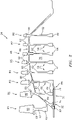
- the compressor section 24 includes a rotor stage 58 including an integrally formed rotor bore 62 and bore basket 72.
- a plurality of rotor blades 60 are attached to the outer radial hub 66 of the rotor bore 62.
- the rotor blades 60 may be integrally formed with the rotor bore 62, or attached by mechanical means. The present disclosure is not limited to any particular method for attaching rotor blades 60 to a rotor bore 62.
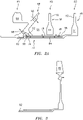
- the bore basket 72 includes a substantially cylindrical structure that includes an inner radial panel 74 and an outer radial panel 76 extending axially between a first axial end 78 and a second axial end 80.
- the inner and outer radial panels 74, 76 may be formed in a single process (e.g., additive manufacturing, etc.) or may be a weldment that forms this portion of the unitary structure described herein.
- the present disclosure is not limited to any particular process for forming the bore basket 72 as a unitary structure.
- the bore basket 72 is attached to an inner radial hub 64 of the rotor bore 62 at the second axial end 80 of the bore basket 72. Non-limiting means of attachment between bore basket 72 and the rotor bore 62 include welding, or the like.
- the present disclosure is not limited to any particular process for attaching the bore basket 72 to the rotor bore 62.
- the integrally formed rotor bore 62 and bore basket 72 may be manufactured in a single process, and the present disclosure is not limited to any process for manufacturing the same.
- the bore basket 72 includes an engagement panel 82 disposed at the first axial end 78.
- the inner radial panel 74 is disposed radially inside of, and separated from, the outer radial panel 76, thereby defining an annular passage 84 there between.
- the annular passage 84 may by circumferentially continuous, or it may be separated into circumferential segments.
- the bore basket 72 includes a plurality of inlet apertures 86 disposed at a first axial position 88, and a plurality of exit apertures 90 disposed at a second axial position 92.
- the second axial position 92 is axially separated from the first axial position 88.
- the plurality of inlet apertures 86 are distributed around the circumference of the bore basket 72.
- the plurality of exit apertures 90 are distributed around the circumference of the bore basket 72.
- the physical characteristics of the inlet and exit apertures 86, 90 may be varied to provide desired metered fluid flow characteristics for different applications. In the embodiment shown in FIG.
- the inlet apertures 86 are disposed within the outer radial panel 76 proximate the second axial end 80 of the bore basket 72, and the exit apertures 90 are disposed within the outer radial panel 76 proximate the first axial end 78 of the bore basket 72.
- the present disclosure is not limited to inlet apertures 86 disposed proximate the second axial end 80 of the bore basket 72 and/or exit apertures 90 disposed proximate the first axial end 78 of the bore basket 72.
- the engagement panel 82 may be configured to mechanically couple with a portion of the hub structure 68 to restrict air flow out of the bore cavity 70. For example, in the embodiments shown in FIGS.
- the engagement panel 82 is coupled with a portion of the hub structure 68 disposed radially inside of the first rotor stage ("R1").
- the mechanical coupling between the engagement panel 82 and the hub structure 68 may take the form of one or more of a press fit, an interference fit, a male/female pair, a threaded engagement, or the like.
- the present disclosure is not limited to any particular engagement panel 82 configuration, and/or any particular type of mechanical coupling between the engagement panel 82 and the hub structure 68.
- the integrally formed rotor bore 62 and bore basket 72 are a unitary structure.
- unitary structure as used herein means a single component, wherein all elements of the bore basket 72 and the rotor bore 62 (e.g., the inner radial panel 74, the outer radial panel 76, the engagement panel 82, and the rotor bore 62) are an inseparable body comprising the same material; e.g., formed of a single material, or a weldment of independent elements, etc.
- the axial length of the bore basket 72 between the first axial end 78 and the second axial end 80 can vary depending on the application.
- the axial length of the bore basket 72 is such that a sub-section 94 of the bore cavity 70 is created that includes one rotor bore 62 (i.e., from rotor stage "R2").
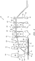
- the axial length of the bore basket 72 is such that a sub-section 194 of the bore cavity 70 is created that includes two rotor bores 62 (from rotor stages "R2" and "R3").
- integrally formed rotor bore 62 and bore basket 72 is not limited to any particular axial length.
- integrally formed rotor bore 62 and bore basket is also limited to forming a bore cavity sub-section that includes any particular number of rotor bores 62; i.e., the formed bore cavity sub-section contains at least one rotor bore 62.
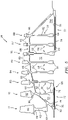
- FIG. 5 illustrates an embodiment wherein the compressor section includes an integrally formed rotor bore 62 and bore basket 72 disposed toward the aft of the compressor section 24.
- the bore basket 72 is as described above.
- Embodiments of the present disclosure include compressor section 24 embodiments that include only a forward disposed integrally formed rotor bore 62 and bore basket 72 (e.g., see FIGS. 2-4 ), or only an aft disposed integrally formed rotor bore 62 and bore basket 72, or both (e.g., see FIG. 5 ).
- a compressor section having an integrally formed rotor bore 62 and bore basket 72 embodiment according to the present disclosure is shown.
- the integrally formed rotor bore 62 and bore basket 72 and the hub structure 68 define a sub-section 94 of the bore cavity 70 that is sealed off from the remainder of the bore cavity 70.
- the sub-section 94 includes one rotor bore 62 (from rotor stage "R2"). Air at a pressure greater than the ambient pressure within the sub-section 94 enters the sub-section 94 through apertures 96 disposed within the hub structure 68. This air (typically at a lower temperature than the air environment adjacent the shafts) may be referred to as conditioning air.
- the conditioning air travels aft through the sub-section 94, and though the radial passages disposed between the rotor bore 62 (from rotor stage "R2") and the outer radial panel 76 of the bore basket 72.
- the conditioning air subsequently enters the annular passage 84 of the bore basket 72 via the inlet apertures 86 and travels forward within the bore basket 72.
- the conditioning air subsequently exits the annular passage 84 through the exit apertures 90, and then exits the bore cavity 70 via apertures 98 within the hub structure 68 and into an adjacent chamber of the gas turbine engine 20.
- the conditioning air thermally conditions (e.g., cools) the included rotor bore 62 (from rotor stage “R2") and the integrally formed rotor bore 62 (from rotor stage “R3") and bore basket 72 that at least partially defines the bore cavity sub-section 94.
- FIGS. 4 and 4A a compressor section having an integrally formed rotor bore 62 and bore basket 72 embodiment according to the present disclosure is shown.
- the integrally formed rotor bore 62 and bore basket 72 and the hub structure 68 define a sub-section 194 of the bore cavity 70 that is sealed off from the remainder of the bore cavity 70.
- the sub-section 194 includes two rotor bores 62 (from rotor stages "R2" and “R3"). Conditioning air (as described above) enters the sub-section 194 through apertures 196 disposed within the hub structure 68.
- the conditioning air travels aft through the sub-section 194, and though the radial passages disposed between the rotor bores 62 (from rotor stages "R2" and “R3") and the outer radial panel 76 of the bore basket 72.
- the conditioning air subsequently enters the annular passage 84 of the bore basket 72 via the inlet apertures 86 and travels forward within the bore basket 72.
- the conditioning air subsequently exits the annular passage 84 through the exit apertures 90, and then exits the bore cavity sub-section 194 via apertures 198 within the hub structure 68 and into an adjacent chamber of the gas turbine engine.
- the conditioning air thermally conditions (e.g., cools) the included rotor bores 62 (from rotor stages “R2" and “R3") and the integrally formed rotor bore 62 (from rotor stage “R4") and bore basket 72 that at least partially defines the bore cavity sub-section 194.
- FIGS. 5 and 5A a compressor section having an integrally formed rotor bore 62 and bore basket 72 embodiment according to the present disclosure is shown.
- the integrally formed rotor bore 62 and bore basket 72 and the hub structure 68 define a sub-section 294 of the bore cavity 70 that is sealed off from the remainder of the bore cavity 70.
- the sub-section 294 includes two rotor bores 62 (from rotor stages "R7" and “R8"). Conditioning air (as described above) enters the sub-section 294 through apertures 296 disposed within the hub structure 68.
- At least a portion of the conditioning air enters the annular passage 84 of the bore basket 72 via the inlet apertures 86 and travels aft within the bore basket 72.
- the conditioning air subsequently exits the annular passage 84 through the exit apertures 90, and then exits the sub-section 294 via apertures 298 and into an adjacent chamber of the gas turbine engine.
- the conditioning air thermally conditions (e.g., cools) the included rotor bores 62 (from rotor stages "R7" and "R8") and the integrally formed rotor bore 62 (from rotor stage “R6") and bore basket 72 that at least partially defines the bore cavity sub-section 294.
- the conditioning fluid circuits within the bore cavity sub-sections 94, 194, 294 (made possible by the integrally formed rotor bore 62 and bore basket 72 embodiments), provide conditioning of the rotor bores 62 within the respective sub-section 94, 194, 294 that facilitates uniform growth of the rotor bores 62 (via thermal expansion) for different rotor bore 62 materials and rotor bore 62 configurations.
- the bore cavity sub-section 94, 194, 294 conditioning also facilitates tip clearance control of the rotor blade tips relative to an outer casing surrounding the rotor blades 60.
- integrally formed rotor bore 62 and bore basket 72 embodiment also provide a bore basket 72 with improved sealing.
- Embodiments of the present disclosure integrally formed rotor bore 62 and bore basket 72 embodiment also provide a bore basket that eliminates mechanical wear points. As stated above, bore baskets formed from a plurality of different elements require joints between elements that permit relative movement between elements, and that relative movement can produce undesirable wear. The present disclosure integrally formed rotor bore 62 and bore basket 72 embodiments do not include such relative movement joints, and thereby avoid potential undesirable wear. Embodiments of the present disclosure integrally formed rotor bore 62 and bore basket 72 also provide a bore basket 72 that decreases the potential for foreign object damage ("FOD").
- FOD foreign object damage
- Bore baskets formed from a plurality of different elements often include smaller elements (e.g., fasteners, anti-rotation keys, etc.). If such elements work free during operation of the gas turbine engine, the aforesaid elements may travel within the engine and can potentially cause damage.
- Embodiments of the present disclosure integrally formed rotor bore 62 and bore basket 72 embodiment do not include such elements and therefore reduce the potential for FOD.
Landscapes
- Engineering & Computer Science (AREA)
- Mechanical Engineering (AREA)
- General Engineering & Computer Science (AREA)
- Chemical & Material Sciences (AREA)
- Combustion & Propulsion (AREA)
- Life Sciences & Earth Sciences (AREA)
- Sustainable Development (AREA)
- Physics & Mathematics (AREA)
- Thermal Sciences (AREA)
- Structures Of Non-Positive Displacement Pumps (AREA)
Claims (12)
- Rotorabschnitt für ein Gasturbinentriebwerk, wobei der Rotorabschnitt Folgendes umfasst:eine erste Rotorbohrung (62) mit einer ersten inneren radialen Nabe (64);einen Bohrungskorb (72), der sich axial zwischen einem ersten axialen Ende und einem zweiten axialen Ende gegenüber dem ersten axialen Ende erstreckt, wobei der Bohrungskorb (72) Folgendes aufweist:eine am ersten axialen Ende angeordnete Eingriffsplatte (82): eine zylindrische innere radiale Platte (74);eine zylindrische äußere radiale Platte (76), wobei die innere radiale Platte (74) und die äußere radiale Platte (76) sich zwischen dem ersten axialen Ende und dem zweiten axialen Ende erstrecken und die innere radiale Platte (74) radial innerhalb davon angeordnet ist und von der äußeren radialen Platte (76) getrennt ist, und ein ringförmiger Durchgang (84) zwischen der inneren radialen Platte (74) und der äußeren radialen Platte (76) angeordnet ist;eine Vielzahl von Einlassöffnungen (86) in Fluidverbindung mit dem ringförmigen Durchgang (84) an einer ersten axialen Position (88); undeine Vielzahl von Austrittsöffnungen (90) in Fluidverbindung mit dem ringförmigen Durchgang (84) an einer zweiten axialen Position (92), wobei die zweite axiale Position (92) von der ersten axialen Position (88) getrennt ist;wobei das zweite axiale Ende des Bohrungskorbs (72) an der ersten inneren radialen Nabe (64) der ersten Rotorbohrung (62) angebracht ist;dadurch gekennzeichnet, dass:die erste Rotorbohrung (62) und der Bohrungskorb (72) eine einheitliche Struktur sind; unddie erste Rotorbohrung (62) und der Bohrungskorb (72) aus demselben Material bestehen.
- Rotorabschnitt nach Anspruch 1, wobei die innere radiale Platte (74) und die äußere radiale Platte (76) miteinander verschweißt sind und der Bohrungskorb (72) und die erste Rotorbohrung (62) miteinander verschweißt sind.
- Rotorabschnitt nach Anspruch 1 oder 2, umfassend:eine Vielzahl von Rotorstufen (58), wobei jede Rotorstufe (58) eine Rotorbohrung (62) mit einer inneren radialen Nabe (64) aufweist, wobei die Rotorstufen (58) durch eine Nabenstruktur (68) miteinander verbunden sind, wobei die Nabenstruktur (68) teilweise einen Bohrungshohlraum (70) definiert;wobei der Bohrungskorb (72) einstückig mit der ersten Rotorbohrung (62) einer ersten Rotorstufe der Vielzahl von Rotorstufen (58) ausgebildet ist und sich das zweite axiale Ende des Bohrungskorbs (72) von der inneren radialen Nabe (64) der ersten Rotorbohrung (62) erstreckt; undwobei die Eingriffsplatte (82) mit der Nabenstruktur (68) verbunden ist; undwobei die Nabenstruktur (68), der Bohrungskorb (72) und die erste Rotorbohrung (62) einen Unterabschnitt (94; 194; 294) des Bohrungshohlraums (70) definieren, wobei der Unterabschnitt eine zweite Rotorbohrung (62) einer zweiten Rotorstufe der Vielzahl von Rotorstufen (58) enthält.
- Rotorabschnitt nach Anspruch 3, wobei der Unterabschnitt (194; 294) mindestens zwei Rotorbohrungen (62) enthält.
- Rotorabschnitt nach einem der Ansprüche 3 oder 4, wobei die Nabenstruktur (68) eine Vielzahl von Nabenstruktur-Einlassöffnungen (96; 196; 296) und eine Vielzahl von Nabenstruktur-Austrittsöffnungen (98; 198; 298) enthält, und die Vielzahl von Nabenstruktur-Einlassöffnungen (96; 196; 296) und die Vielzahl von Nabenstruktur-Austrittsöffnungen (98; 198; 298) in Fluidverbindung mit dem Unterabschnitt (94; 194; 294) des Bohrungshohlraums (70) stehen.
- Rotorabschnitt nach einem der Ansprüche 3 bis 5, wobei der Unterabschnitt (94; 194) an einem vorderen Teil des Bohrungshohlraums (70) angeordnet ist.
- Rotorabschnitt nach einem der Ansprüche 3 bis 6, wobei der Unterabschnitt (294) an einem hinteren Teil des Bohrungshohlraums (70) angeordnet ist.
- Rotorabschnitt nach einem der Ansprüche 3 bis 7, ferner umfassend einen zweiten Bohrungskorb (72) mit:einer zweiten Eingriffsplatte (82);einer zweiten zylindrischen innere radiale Platte (74);einer zweiten zylindrischen äußere radiale Platte (76), wobei sich die zweite innere radiale Platte (74) und die zweite äußere radiale Platte (76) axial erstrecken und die zweite innere radiale Platte (74) radial innerhalb davon angeordnet ist und von der zweiten äußeren radialen Platte (76) getrennt ist, und ein zweiter ringförmiger Durchgang (84) zwischen der zweiten inneren radialen Platte (74) und der zweiten äußeren radialen Platte (76) angeordnet ist;einer Vielzahl von zweiten Einlassöffnungen (86) in Fluidverbindung mit dem zweiten ringförmigen Durchgang (84); und einer Vielzahl von zweiten Austrittsöffnungen (90) in Fluidverbindung mit dem zweiten ringförmigen Durchgang (84), wobei die zweiten Einlassöffnungen (86) axial von den zweiten Austrittsöffnungen (90) getrennt sind;wobei der zweite Bohrungskorb (72) einstückig mit einer dritten Rotorbohrung (62) einer dritten Rotorstufe der Vielzahl von Rotorstufen (58) ausgebildet ist und sich von der inneren radialen Nabe (64) der dritten Rotorbohrung (62) erstreckt; und wobei die zweite Eingriffsplatte (82) mit der Nabenstruktur (68) verbunden ist; undwobei die Nabenstruktur (68), der zweite Bohrungskorb (72) und die dritte Rotorbohrung (62) einen zweiten Unterabschnitt (94; 194; 294) des Bohrungshohlraums (70) definieren, wobei der zweite Teilabschnitt (94; 194; 294) eine vierte Rotorbohrung (62) einer vierten Rotorstufe der Vielzahl von Rotorstufen (58) enthält.
- Rotorabschnitt nach einem der Ansprüche 3 bis 8, wobei der Rotorabschnitt ein Verdichterabschnitt (24) oder ein Turbinenabschnitt (28) ist.
- Rotorabschnitt nach einem der vorhergehenden Ansprüche, wobei sich die Vielzahl von Einlassöffnungen (86) an der ersten axialen Position (88) durch die äußere radiale Platte (76) erstrecken.
- Rotorabschnitt nach einem der vorhergehenden Ansprüche, wobei sich die Vielzahl von Austrittsöffnungen (90) an der zweiten axialen Position (92) durch die äußere radiale Platte (76) erstrecken.
- Rotorabschnitt nach einem der vorhergehenden Ansprüche, wobei die Vielzahl von Einlassöffnungen (86) und die Vielzahl von Austrittsöffnungen (90) in Umfangsrichtung um die äußere radiale Platte (76) herum angeordnet sind.
Applications Claiming Priority (1)
| Application Number | Priority Date | Filing Date | Title |
|---|---|---|---|
| US16/797,839 US11067090B1 (en) | 2020-02-21 | 2020-02-21 | Integral rotor bore and bore basket |
Publications (2)
| Publication Number | Publication Date |
|---|---|
| EP3869006A1 EP3869006A1 (de) | 2021-08-25 |
| EP3869006B1 true EP3869006B1 (de) | 2022-10-05 |
Family
ID=73856425
Family Applications (1)
| Application Number | Title | Priority Date | Filing Date |
|---|---|---|---|
| EP20216101.4A Active EP3869006B1 (de) | 2020-02-21 | 2020-12-21 | Rotorscheibe mit integralem bohrungskorb |
Country Status (2)
| Country | Link |
|---|---|
| US (1) | US11067090B1 (de) |
| EP (1) | EP3869006B1 (de) |
Families Citing this family (1)
| Publication number | Priority date | Publication date | Assignee | Title |
|---|---|---|---|---|
| US20250389200A1 (en) * | 2024-06-19 | 2025-12-25 | Rtx Corporation | Center Tie Rotor Annular Seal |
Family Cites Families (7)
| Publication number | Priority date | Publication date | Assignee | Title |
|---|---|---|---|---|
| US5271711A (en) | 1992-05-11 | 1993-12-21 | General Electric Company | Compressor bore cooling manifold |
| FR2892148B1 (fr) | 2005-10-19 | 2011-07-22 | Snecma | Fourreau d'arbre de turboreacteur et turboreacteur comportant ce fourreau |
| EP2910735B1 (de) | 2014-02-21 | 2020-07-01 | United Technologies Corporation | Bohrlochkorb für eine gasbetriebene turbine |
| US10280792B2 (en) * | 2014-02-21 | 2019-05-07 | United Technologies Corporation | Bore basket for a gas powered turbine |
| US10563672B2 (en) * | 2018-02-07 | 2020-02-18 | United Technologies Corporation | Gas turbine engine compressor |
| US10760494B2 (en) * | 2018-03-18 | 2020-09-01 | Raytheon Technologies Corporation | Telescoping bore basket for gas turbine engine |
| US10808627B2 (en) * | 2018-03-26 | 2020-10-20 | Raytheon Technologies Corporation | Double bore basket |
-
2020
- 2020-02-21 US US16/797,839 patent/US11067090B1/en active Active
- 2020-12-21 EP EP20216101.4A patent/EP3869006B1/de active Active
Also Published As
| Publication number | Publication date |
|---|---|
| US11067090B1 (en) | 2021-07-20 |
| EP3869006A1 (de) | 2021-08-25 |
Similar Documents
| Publication | Publication Date | Title |
|---|---|---|
| EP3734018B1 (de) | Dichtung für ein gasturbinentriebwerks-bauteil und zugehöriges verfahren | |
| EP3730744A1 (de) | Abdichtung für die schiene einer plattform einer turbinenleitschaufel | |
| EP3348803B1 (de) | Motormittelturbinenrahmen-transferröhre zur kühlung eines niederdruckturbinengehäuses | |
| EP3524777B1 (de) | Hochdruckverdichterrotorpaket, zugehöriger gasturbinenmotor und verfahren zum leiten eines fluids durch ein hochdruckverdichterrotorpaket | |
| WO2014189579A2 (en) | Rotatable full ring fairing for a turbine engine | |
| EP3030755B1 (de) | Abstandskontrollanordnung mit spezifischer anordnung eines abstandskontrollrings | |
| EP3190266B1 (de) | Gasturbine mit rotornabendichtung | |
| EP3382279B1 (de) | Zwischenscheibe für brennkammeranordnung | |
| EP3708773B1 (de) | Gasturbinentriebwerk mit dichtung für einen rotorstapel und zugehöriges verfahren zum abdichten einer welle gegenüber einer rotorscheibe | |
| EP3543462B1 (de) | Teleskopischer bohrlochkorb für einen gasturbinenmotor | |
| EP3869006B1 (de) | Rotorscheibe mit integralem bohrungskorb | |
| EP3450685B1 (de) | Gasturbinenmotorkomponente | |
| EP2995778B1 (de) | Verfahren und anordnung zur verminderung sekundärer wärme in einem gasturbinenmotor | |
| US11619136B2 (en) | Fatigue resistant blade outer air seal | |
| US11649729B2 (en) | Anti-vortex tube retaining ring and bore basket | |
| EP3760841B1 (de) | Mehrzweckdrehsicherungssperrbolzen | |
| EP3748133B1 (de) | Ermüdungsbeständige schaufelaussenluftdichtung | |
| US11199104B2 (en) | Seal anti-rotation | |
| US11814977B1 (en) | Thermal conditioning of flange with secondary flow | |
| US20240151152A1 (en) | Seal for gas turbine engine | |
| EP3715641B1 (de) | Gekerbter axialflansch für einen kompressor mit geteiltem gehäuse | |
| EP3392472B1 (de) | Verdichterteil für einen gasturbinenmotor sowie zugehöriges gasturbinentriebwerk und verfahren zum betreiben eines verdichterteils in einem gasturbinentriebwerk |
Legal Events
| Date | Code | Title | Description |
|---|---|---|---|
| PUAI | Public reference made under article 153(3) epc to a published international application that has entered the european phase |
Free format text: ORIGINAL CODE: 0009012 |
|
| STAA | Information on the status of an ep patent application or granted ep patent |
Free format text: STATUS: THE APPLICATION HAS BEEN PUBLISHED |
|
| AK | Designated contracting states |
Kind code of ref document: A1 Designated state(s): AL AT BE BG CH CY CZ DE DK EE ES FI FR GB GR HR HU IE IS IT LI LT LU LV MC MK MT NL NO PL PT RO RS SE SI SK SM TR |
|
| STAA | Information on the status of an ep patent application or granted ep patent |
Free format text: STATUS: REQUEST FOR EXAMINATION WAS MADE |
|
| 17P | Request for examination filed |
Effective date: 20220224 |
|
| RBV | Designated contracting states (corrected) |
Designated state(s): AL AT BE BG CH CY CZ DE DK EE ES FI FR GB GR HR HU IE IS IT LI LT LU LV MC MK MT NL NO PL PT RO RS SE SI SK SM TR |
|
| RIC1 | Information provided on ipc code assigned before grant |
Ipc: F04D 29/32 20060101ALI20220311BHEP Ipc: F04D 29/044 20060101ALI20220311BHEP Ipc: F02C 9/18 20060101ALI20220311BHEP Ipc: F02C 7/18 20060101ALI20220311BHEP Ipc: F01D 5/08 20060101AFI20220311BHEP |
|
| GRAP | Despatch of communication of intention to grant a patent |
Free format text: ORIGINAL CODE: EPIDOSNIGR1 |
|
| STAA | Information on the status of an ep patent application or granted ep patent |
Free format text: STATUS: GRANT OF PATENT IS INTENDED |
|
| RIN1 | Information on inventor provided before grant (corrected) |
Inventor name: GIANNAKOPOULOS, KONSTANTINOS P. |
|
| INTG | Intention to grant announced |
Effective date: 20220426 |
|
| GRAS | Grant fee paid |
Free format text: ORIGINAL CODE: EPIDOSNIGR3 |
|
| GRAA | (expected) grant |
Free format text: ORIGINAL CODE: 0009210 |
|
| STAA | Information on the status of an ep patent application or granted ep patent |
Free format text: STATUS: THE PATENT HAS BEEN GRANTED |
|
| AK | Designated contracting states |
Kind code of ref document: B1 Designated state(s): AL AT BE BG CH CY CZ DE DK EE ES FI FR GB GR HR HU IE IS IT LI LT LU LV MC MK MT NL NO PL PT RO RS SE SI SK SM TR |
|
| REG | Reference to a national code |
Ref country code: GB Ref legal event code: FG4D |
|
| REG | Reference to a national code |
Ref country code: CH Ref legal event code: EP |
|
| REG | Reference to a national code |
Ref country code: AT Ref legal event code: REF Ref document number: 1522870 Country of ref document: AT Kind code of ref document: T Effective date: 20221015 |
|
| REG | Reference to a national code |
Ref country code: IE Ref legal event code: FG4D |
|
| REG | Reference to a national code |
Ref country code: DE Ref legal event code: R096 Ref document number: 602020005486 Country of ref document: DE |
|
| REG | Reference to a national code |
Ref country code: LT Ref legal event code: MG9D |
|
| REG | Reference to a national code |
Ref country code: NL Ref legal event code: MP Effective date: 20221005 |
|
| REG | Reference to a national code |
Ref country code: AT Ref legal event code: MK05 Ref document number: 1522870 Country of ref document: AT Kind code of ref document: T Effective date: 20221005 |
|
| PG25 | Lapsed in a contracting state [announced via postgrant information from national office to epo] |
Ref country code: NL Free format text: LAPSE BECAUSE OF FAILURE TO SUBMIT A TRANSLATION OF THE DESCRIPTION OR TO PAY THE FEE WITHIN THE PRESCRIBED TIME-LIMIT Effective date: 20221005 |
|
| PG25 | Lapsed in a contracting state [announced via postgrant information from national office to epo] |
Ref country code: SE Free format text: LAPSE BECAUSE OF FAILURE TO SUBMIT A TRANSLATION OF THE DESCRIPTION OR TO PAY THE FEE WITHIN THE PRESCRIBED TIME-LIMIT Effective date: 20221005 Ref country code: PT Free format text: LAPSE BECAUSE OF FAILURE TO SUBMIT A TRANSLATION OF THE DESCRIPTION OR TO PAY THE FEE WITHIN THE PRESCRIBED TIME-LIMIT Effective date: 20230206 Ref country code: NO Free format text: LAPSE BECAUSE OF FAILURE TO SUBMIT A TRANSLATION OF THE DESCRIPTION OR TO PAY THE FEE WITHIN THE PRESCRIBED TIME-LIMIT Effective date: 20230105 Ref country code: LT Free format text: LAPSE BECAUSE OF FAILURE TO SUBMIT A TRANSLATION OF THE DESCRIPTION OR TO PAY THE FEE WITHIN THE PRESCRIBED TIME-LIMIT Effective date: 20221005 Ref country code: FI Free format text: LAPSE BECAUSE OF FAILURE TO SUBMIT A TRANSLATION OF THE DESCRIPTION OR TO PAY THE FEE WITHIN THE PRESCRIBED TIME-LIMIT Effective date: 20221005 Ref country code: ES Free format text: LAPSE BECAUSE OF FAILURE TO SUBMIT A TRANSLATION OF THE DESCRIPTION OR TO PAY THE FEE WITHIN THE PRESCRIBED TIME-LIMIT Effective date: 20221005 Ref country code: AT Free format text: LAPSE BECAUSE OF FAILURE TO SUBMIT A TRANSLATION OF THE DESCRIPTION OR TO PAY THE FEE WITHIN THE PRESCRIBED TIME-LIMIT Effective date: 20221005 |
|
| PG25 | Lapsed in a contracting state [announced via postgrant information from national office to epo] |
Ref country code: RS Free format text: LAPSE BECAUSE OF FAILURE TO SUBMIT A TRANSLATION OF THE DESCRIPTION OR TO PAY THE FEE WITHIN THE PRESCRIBED TIME-LIMIT Effective date: 20221005 Ref country code: PL Free format text: LAPSE BECAUSE OF FAILURE TO SUBMIT A TRANSLATION OF THE DESCRIPTION OR TO PAY THE FEE WITHIN THE PRESCRIBED TIME-LIMIT Effective date: 20221005 Ref country code: LV Free format text: LAPSE BECAUSE OF FAILURE TO SUBMIT A TRANSLATION OF THE DESCRIPTION OR TO PAY THE FEE WITHIN THE PRESCRIBED TIME-LIMIT Effective date: 20221005 Ref country code: IS Free format text: LAPSE BECAUSE OF FAILURE TO SUBMIT A TRANSLATION OF THE DESCRIPTION OR TO PAY THE FEE WITHIN THE PRESCRIBED TIME-LIMIT Effective date: 20230205 Ref country code: HR Free format text: LAPSE BECAUSE OF FAILURE TO SUBMIT A TRANSLATION OF THE DESCRIPTION OR TO PAY THE FEE WITHIN THE PRESCRIBED TIME-LIMIT Effective date: 20221005 Ref country code: GR Free format text: LAPSE BECAUSE OF FAILURE TO SUBMIT A TRANSLATION OF THE DESCRIPTION OR TO PAY THE FEE WITHIN THE PRESCRIBED TIME-LIMIT Effective date: 20230106 |
|
| P01 | Opt-out of the competence of the unified patent court (upc) registered |
Effective date: 20230521 |
|
| REG | Reference to a national code |
Ref country code: DE Ref legal event code: R097 Ref document number: 602020005486 Country of ref document: DE |
|
| PG25 | Lapsed in a contracting state [announced via postgrant information from national office to epo] |
Ref country code: SM Free format text: LAPSE BECAUSE OF FAILURE TO SUBMIT A TRANSLATION OF THE DESCRIPTION OR TO PAY THE FEE WITHIN THE PRESCRIBED TIME-LIMIT Effective date: 20221005 Ref country code: RO Free format text: LAPSE BECAUSE OF FAILURE TO SUBMIT A TRANSLATION OF THE DESCRIPTION OR TO PAY THE FEE WITHIN THE PRESCRIBED TIME-LIMIT Effective date: 20221005 Ref country code: EE Free format text: LAPSE BECAUSE OF FAILURE TO SUBMIT A TRANSLATION OF THE DESCRIPTION OR TO PAY THE FEE WITHIN THE PRESCRIBED TIME-LIMIT Effective date: 20221005 Ref country code: DK Free format text: LAPSE BECAUSE OF FAILURE TO SUBMIT A TRANSLATION OF THE DESCRIPTION OR TO PAY THE FEE WITHIN THE PRESCRIBED TIME-LIMIT Effective date: 20221005 Ref country code: CZ Free format text: LAPSE BECAUSE OF FAILURE TO SUBMIT A TRANSLATION OF THE DESCRIPTION OR TO PAY THE FEE WITHIN THE PRESCRIBED TIME-LIMIT Effective date: 20221005 |
|
| PLBE | No opposition filed within time limit |
Free format text: ORIGINAL CODE: 0009261 |
|
| STAA | Information on the status of an ep patent application or granted ep patent |
Free format text: STATUS: NO OPPOSITION FILED WITHIN TIME LIMIT |
|
| REG | Reference to a national code |
Ref country code: BE Ref legal event code: MM Effective date: 20221231 |
|
| PG25 | Lapsed in a contracting state [announced via postgrant information from national office to epo] |
Ref country code: SK Free format text: LAPSE BECAUSE OF FAILURE TO SUBMIT A TRANSLATION OF THE DESCRIPTION OR TO PAY THE FEE WITHIN THE PRESCRIBED TIME-LIMIT Effective date: 20221005 Ref country code: LU Free format text: LAPSE BECAUSE OF NON-PAYMENT OF DUE FEES Effective date: 20221221 Ref country code: AL Free format text: LAPSE BECAUSE OF FAILURE TO SUBMIT A TRANSLATION OF THE DESCRIPTION OR TO PAY THE FEE WITHIN THE PRESCRIBED TIME-LIMIT Effective date: 20221005 |
|
| 26N | No opposition filed |
Effective date: 20230706 |
|
| PG25 | Lapsed in a contracting state [announced via postgrant information from national office to epo] |
Ref country code: IE Free format text: LAPSE BECAUSE OF NON-PAYMENT OF DUE FEES Effective date: 20221221 |
|
| PG25 | Lapsed in a contracting state [announced via postgrant information from national office to epo] |
Ref country code: SI Free format text: LAPSE BECAUSE OF FAILURE TO SUBMIT A TRANSLATION OF THE DESCRIPTION OR TO PAY THE FEE WITHIN THE PRESCRIBED TIME-LIMIT Effective date: 20221005 Ref country code: BE Free format text: LAPSE BECAUSE OF NON-PAYMENT OF DUE FEES Effective date: 20221231 |
|
| PG25 | Lapsed in a contracting state [announced via postgrant information from national office to epo] |
Ref country code: CY Free format text: LAPSE BECAUSE OF FAILURE TO SUBMIT A TRANSLATION OF THE DESCRIPTION OR TO PAY THE FEE WITHIN THE PRESCRIBED TIME-LIMIT Effective date: 20221005 |
|
| PG25 | Lapsed in a contracting state [announced via postgrant information from national office to epo] |
Ref country code: MK Free format text: LAPSE BECAUSE OF FAILURE TO SUBMIT A TRANSLATION OF THE DESCRIPTION OR TO PAY THE FEE WITHIN THE PRESCRIBED TIME-LIMIT Effective date: 20221005 Ref country code: IT Free format text: LAPSE BECAUSE OF FAILURE TO SUBMIT A TRANSLATION OF THE DESCRIPTION OR TO PAY THE FEE WITHIN THE PRESCRIBED TIME-LIMIT Effective date: 20221005 |
|
| PG25 | Lapsed in a contracting state [announced via postgrant information from national office to epo] |
Ref country code: MC Free format text: LAPSE BECAUSE OF FAILURE TO SUBMIT A TRANSLATION OF THE DESCRIPTION OR TO PAY THE FEE WITHIN THE PRESCRIBED TIME-LIMIT Effective date: 20221005 |
|
| PG25 | Lapsed in a contracting state [announced via postgrant information from national office to epo] |
Ref country code: MC Free format text: LAPSE BECAUSE OF FAILURE TO SUBMIT A TRANSLATION OF THE DESCRIPTION OR TO PAY THE FEE WITHIN THE PRESCRIBED TIME-LIMIT Effective date: 20221005 |
|
| PG25 | Lapsed in a contracting state [announced via postgrant information from national office to epo] |
Ref country code: BG Free format text: LAPSE BECAUSE OF FAILURE TO SUBMIT A TRANSLATION OF THE DESCRIPTION OR TO PAY THE FEE WITHIN THE PRESCRIBED TIME-LIMIT Effective date: 20221005 |
|
| REG | Reference to a national code |
Ref country code: CH Ref legal event code: PL |
|
| PG25 | Lapsed in a contracting state [announced via postgrant information from national office to epo] |
Ref country code: MT Free format text: LAPSE BECAUSE OF FAILURE TO SUBMIT A TRANSLATION OF THE DESCRIPTION OR TO PAY THE FEE WITHIN THE PRESCRIBED TIME-LIMIT Effective date: 20221005 |
|
| PG25 | Lapsed in a contracting state [announced via postgrant information from national office to epo] |
Ref country code: CH Free format text: LAPSE BECAUSE OF NON-PAYMENT OF DUE FEES Effective date: 20231231 |
|
| PG25 | Lapsed in a contracting state [announced via postgrant information from national office to epo] |
Ref country code: CH Free format text: LAPSE BECAUSE OF NON-PAYMENT OF DUE FEES Effective date: 20231231 |
|
| PG25 | Lapsed in a contracting state [announced via postgrant information from national office to epo] |
Ref country code: HU Free format text: LAPSE BECAUSE OF FAILURE TO SUBMIT A TRANSLATION OF THE DESCRIPTION OR TO PAY THE FEE WITHIN THE PRESCRIBED TIME-LIMIT; INVALID AB INITIO Effective date: 20201221 |
|
| REG | Reference to a national code |
Ref country code: DE Ref legal event code: R081 Ref document number: 602020005486 Country of ref document: DE Owner name: RTX CORPORATION (N.D.GES.D. STAATES DELAWARE),, US Free format text: FORMER OWNER: RAYTHEON TECHNOLOGIES CORPORATION, FARMINGTON, CT, US |
|
| PG25 | Lapsed in a contracting state [announced via postgrant information from national office to epo] |
Ref country code: TR Free format text: LAPSE BECAUSE OF FAILURE TO SUBMIT A TRANSLATION OF THE DESCRIPTION OR TO PAY THE FEE WITHIN THE PRESCRIBED TIME-LIMIT Effective date: 20221005 |
|
| PGFP | Annual fee paid to national office [announced via postgrant information from national office to epo] |
Ref country code: DE Payment date: 20251126 Year of fee payment: 6 |
|
| PGFP | Annual fee paid to national office [announced via postgrant information from national office to epo] |
Ref country code: GB Payment date: 20251119 Year of fee payment: 6 |
|
| PGFP | Annual fee paid to national office [announced via postgrant information from national office to epo] |
Ref country code: FR Payment date: 20251120 Year of fee payment: 6 |