EP3869035B1 - Pale pour un rotor d'éolienne et son procédé de fabrication - Google Patents
Pale pour un rotor d'éolienne et son procédé de fabrication Download PDFInfo
- Publication number
- EP3869035B1 EP3869035B1 EP20380009.9A EP20380009A EP3869035B1 EP 3869035 B1 EP3869035 B1 EP 3869035B1 EP 20380009 A EP20380009 A EP 20380009A EP 3869035 B1 EP3869035 B1 EP 3869035B1
- Authority
- EP
- European Patent Office
- Prior art keywords
- layer
- electrical connector
- blade
- shell
- contact
- Prior art date
- Legal status (The legal status is an assumption and is not a legal conclusion. Google has not performed a legal analysis and makes no representation as to the accuracy of the status listed.)
- Active
Links
Images


Classifications
-
- F—MECHANICAL ENGINEERING; LIGHTING; HEATING; WEAPONS; BLASTING
- F03—MACHINES OR ENGINES FOR LIQUIDS; WIND, SPRING, OR WEIGHT MOTORS; PRODUCING MECHANICAL POWER OR A REACTIVE PROPULSIVE THRUST, NOT OTHERWISE PROVIDED FOR
- F03D—WIND MOTORS
- F03D1/00—Wind motors with rotation axis substantially parallel to the air flow entering the rotor
- F03D1/06—Rotors
- F03D1/065—Rotors characterised by their construction elements
- F03D1/0675—Rotors characterised by their construction elements of the blades
-
- B—PERFORMING OPERATIONS; TRANSPORTING
- B29—WORKING OF PLASTICS; WORKING OF SUBSTANCES IN A PLASTIC STATE IN GENERAL
- B29C—SHAPING OR JOINING OF PLASTICS; SHAPING OF MATERIAL IN A PLASTIC STATE, NOT OTHERWISE PROVIDED FOR; AFTER-TREATMENT OF THE SHAPED PRODUCTS, e.g. REPAIRING
- B29C70/00—Shaping composites, i.e. plastics material comprising reinforcements, fillers or preformed parts, e.g. inserts
- B29C70/04—Shaping composites, i.e. plastics material comprising reinforcements, fillers or preformed parts, e.g. inserts comprising reinforcements only, e.g. self-reinforcing plastics
- B29C70/28—Shaping operations therefor
- B29C70/30—Shaping by lay-up, i.e. applying fibres, tape or broadsheet on a mould, former or core; Shaping by spray-up, i.e. spraying of fibres on a mould, former or core
- B29C70/36—Shaping by lay-up, i.e. applying fibres, tape or broadsheet on a mould, former or core; Shaping by spray-up, i.e. spraying of fibres on a mould, former or core and impregnating by casting, e.g. vacuum casting
-
- B—PERFORMING OPERATIONS; TRANSPORTING
- B29—WORKING OF PLASTICS; WORKING OF SUBSTANCES IN A PLASTIC STATE IN GENERAL
- B29D—PRODUCING PARTICULAR ARTICLES FROM PLASTICS OR FROM SUBSTANCES IN A PLASTIC STATE
- B29D99/00—Subject matter not provided for in other groups of this subclass
- B29D99/0025—Producing blades or the like, e.g. blades for turbines, propellers, or wings
-
- F—MECHANICAL ENGINEERING; LIGHTING; HEATING; WEAPONS; BLASTING
- F03—MACHINES OR ENGINES FOR LIQUIDS; WIND, SPRING, OR WEIGHT MOTORS; PRODUCING MECHANICAL POWER OR A REACTIVE PROPULSIVE THRUST, NOT OTHERWISE PROVIDED FOR
- F03D—WIND MOTORS
- F03D80/00—Details, components or accessories not provided for in groups F03D1/00 - F03D17/00
- F03D80/40—Ice detection; De-icing means
-
- F—MECHANICAL ENGINEERING; LIGHTING; HEATING; WEAPONS; BLASTING
- F03—MACHINES OR ENGINES FOR LIQUIDS; WIND, SPRING, OR WEIGHT MOTORS; PRODUCING MECHANICAL POWER OR A REACTIVE PROPULSIVE THRUST, NOT OTHERWISE PROVIDED FOR
- F03D—WIND MOTORS
- F03D80/00—Details, components or accessories not provided for in groups F03D1/00 - F03D17/00
- F03D80/60—Cooling or heating of wind motors
-
- B—PERFORMING OPERATIONS; TRANSPORTING
- B29—WORKING OF PLASTICS; WORKING OF SUBSTANCES IN A PLASTIC STATE IN GENERAL
- B29K—INDEXING SCHEME ASSOCIATED WITH SUBCLASSES B29B, B29C OR B29D, RELATING TO MOULDING MATERIALS OR TO MATERIALS FOR MOULDS, REINFORCEMENTS, FILLERS OR PREFORMED PARTS, e.g. INSERTS
- B29K2105/00—Condition, form or state of moulded material or of the material to be shaped
- B29K2105/06—Condition, form or state of moulded material or of the material to be shaped containing reinforcements, fillers or inserts
- B29K2105/08—Condition, form or state of moulded material or of the material to be shaped containing reinforcements, fillers or inserts of continuous length, e.g. cords, rovings, mats, fabrics, strands or yarns
- B29K2105/0809—Fabrics
-
- B—PERFORMING OPERATIONS; TRANSPORTING
- B29—WORKING OF PLASTICS; WORKING OF SUBSTANCES IN A PLASTIC STATE IN GENERAL
- B29K—INDEXING SCHEME ASSOCIATED WITH SUBCLASSES B29B, B29C OR B29D, RELATING TO MOULDING MATERIALS OR TO MATERIALS FOR MOULDS, REINFORCEMENTS, FILLERS OR PREFORMED PARTS, e.g. INSERTS
- B29K2309/00—Use of inorganic materials not provided for in groups B29K2303/00 - B29K2307/00, as reinforcement
- B29K2309/08—Glass
-
- B—PERFORMING OPERATIONS; TRANSPORTING
- B29—WORKING OF PLASTICS; WORKING OF SUBSTANCES IN A PLASTIC STATE IN GENERAL
- B29L—INDEXING SCHEME ASSOCIATED WITH SUBCLASS B29C, RELATING TO PARTICULAR ARTICLES
- B29L2031/00—Other particular articles
- B29L2031/08—Blades for rotors, stators, fans, turbines or the like, e.g. screw propellers
- B29L2031/082—Blades, e.g. for helicopters
- B29L2031/085—Wind turbine blades
-
- F—MECHANICAL ENGINEERING; LIGHTING; HEATING; WEAPONS; BLASTING
- F05—INDEXING SCHEMES RELATING TO ENGINES OR PUMPS IN VARIOUS SUBCLASSES OF CLASSES F01-F04
- F05B—INDEXING SCHEME RELATING TO WIND, SPRING, WEIGHT, INERTIA OR LIKE MOTORS, TO MACHINES OR ENGINES FOR LIQUIDS COVERED BY SUBCLASSES F03B, F03D AND F03G
- F05B2230/00—Manufacture
- F05B2230/30—Manufacture with deposition of material
- F05B2230/31—Layer deposition
-
- F—MECHANICAL ENGINEERING; LIGHTING; HEATING; WEAPONS; BLASTING
- F05—INDEXING SCHEMES RELATING TO ENGINES OR PUMPS IN VARIOUS SUBCLASSES OF CLASSES F01-F04
- F05B—INDEXING SCHEME RELATING TO WIND, SPRING, WEIGHT, INERTIA OR LIKE MOTORS, TO MACHINES OR ENGINES FOR LIQUIDS COVERED BY SUBCLASSES F03B, F03D AND F03G
- F05B2240/00—Components
- F05B2240/20—Rotors
- F05B2240/30—Characteristics of rotor blades, i.e. of any element transforming dynamic fluid energy to or from rotational energy and being attached to a rotor
-
- F—MECHANICAL ENGINEERING; LIGHTING; HEATING; WEAPONS; BLASTING
- F05—INDEXING SCHEMES RELATING TO ENGINES OR PUMPS IN VARIOUS SUBCLASSES OF CLASSES F01-F04
- F05B—INDEXING SCHEME RELATING TO WIND, SPRING, WEIGHT, INERTIA OR LIKE MOTORS, TO MACHINES OR ENGINES FOR LIQUIDS COVERED BY SUBCLASSES F03B, F03D AND F03G
- F05B2240/00—Components
- F05B2240/85—Electrical connection arrangements
-
- Y—GENERAL TAGGING OF NEW TECHNOLOGICAL DEVELOPMENTS; GENERAL TAGGING OF CROSS-SECTIONAL TECHNOLOGIES SPANNING OVER SEVERAL SECTIONS OF THE IPC; TECHNICAL SUBJECTS COVERED BY FORMER USPC CROSS-REFERENCE ART COLLECTIONS [XRACs] AND DIGESTS
- Y02—TECHNOLOGIES OR APPLICATIONS FOR MITIGATION OR ADAPTATION AGAINST CLIMATE CHANGE
- Y02E—REDUCTION OF GREENHOUSE GAS [GHG] EMISSIONS, RELATED TO ENERGY GENERATION, TRANSMISSION OR DISTRIBUTION
- Y02E10/00—Energy generation through renewable energy sources
- Y02E10/70—Wind energy
- Y02E10/72—Wind turbines with rotation axis in wind direction
-
- Y—GENERAL TAGGING OF NEW TECHNOLOGICAL DEVELOPMENTS; GENERAL TAGGING OF CROSS-SECTIONAL TECHNOLOGIES SPANNING OVER SEVERAL SECTIONS OF THE IPC; TECHNICAL SUBJECTS COVERED BY FORMER USPC CROSS-REFERENCE ART COLLECTIONS [XRACs] AND DIGESTS
- Y02—TECHNOLOGIES OR APPLICATIONS FOR MITIGATION OR ADAPTATION AGAINST CLIMATE CHANGE
- Y02P—CLIMATE CHANGE MITIGATION TECHNOLOGIES IN THE PRODUCTION OR PROCESSING OF GOODS
- Y02P70/00—Climate change mitigation technologies in the production process for final industrial or consumer products
- Y02P70/50—Manufacturing or production processes characterised by the final manufactured product
Definitions
- the present subject matter relates generally to wind turbines blades and, more particularly, to an anti and/or de-icing blade and to a manufacturing method for said blade which yields a simpler and cheaper to manufacture anti and/or de-icing blade which is reliable, effective and accurate for blades comprising multiple heating elements.
- Wind turbine blades are the core components used by modern wind turbines to capture wind energy.
- the aerodynamic characteristics of the blades have a crucial impact on the efficiency of wind turbines.
- ice on the surface of the blade may occur. Icing will change the existing aerodynamic shape of the blade, which will cause harm to the safe operation of the wind turbine.
- After the surface of the blade freezes its natural frequency changes, which causes the dynamic response behavior of the blade to change, which will cause interference to the control behavior of the control system.
- the integrity of the wind turbine structure itself is also affected by the frozen blades. The effects of imbalance or asymmetry increases the fatigue loads of the wind turbine.
- the blade By arranging a heating layer on the surface or inner layer of the blade, the blade can be heated to prevent ice from freezing on the surface when ice formation is to occur, or heating can be initiated after the surface has frozen to cause the ice layer on the surface to melt and achieve the purpose of deicing.
- the heating unit used in the existing heating anti-icing system is either uniformly disposed on the surface of the blade or divided into several heating zones along the length direction.
- the required heat power demand per square meter is different along the blade being lower at shorter radiuses near the root of the blade and higher as the radius approaches the tip of the blade. Likewise, the required heat flux is higher closer to the leading edge and decreases gradually towards the trailing edge.
- the surface to be heated covers the leading edge until a certain distance towards the trailing edge, and that this distance may not be constant along the blade.
- Some solutions are known for heating a blade comprising multiple resistors along the blade longitudinal axis and therebetween the leading edge and the trailing edge, wherein the heating system is installed after the manufacturing and demolding of the blade.
- document EP2526292B1 describes a method for connecting resistor electrodes placed at the outer surface with the required wires for injecting the power inside the blade by means of a conductive sheet in contact with a heating mat.
- Document EP2715128B1 describes a solution for the electrical connections of carbon fiber heating mats which are to be integrated on a finished blade.
- Documents EP3530938 and DE202018102696 describe a blade for a rotor of a wind turbine with an heating element layer and an electrical connector layer.
- a wind turbine blade is disclosed herein with which it has been found that at least the above disadvantages relating to the prior art solutions are mitigated.
- a wind turbine blade for a rotor of a wind turbine comprising a profiled contour formed by a pressure side shell and a suction side shell rigidly joined thereof, said blade comprising a blade root, a blade tip, a leading edge and a trailing edge with a chord c extending therebetween, said shells comprising:
- each shell further comprises second glass fabric layers outwardly in contact with the heating elements layer or the electrical connector layer. I.e. the heating elements layer and the electrical connector layer are placed therebetween glass fabric layers.
- Said heating element layer may be call also a first heating element layer hereafter.
- the first heating element layer may be inwardly or outwardly in contact with the electrical connector layer. I.e. the order in which they are placed within the shell can vary as long as they are electrically in contact.
- each shell further comprises a second electrical connector layer electrically in contact with the connector component wherein the heating element layer is therebetween the electrical connector layer and the second electrical connector layer.
- the blade comprises a second heating element layer electrically and outwardly in contact with the electrical connector layer of each shell may be placed at the leading edge covering both shells, said second heating element layer extending therebetween the leading edge and the trailing edge and adjacently to the heating element layers previously installed in the mold of both shells.
- the first heating element layer before described is applied during manufacturing of the shells and this particular second heating element layer is applied after the pressure shell and suction shell are rigidly joined.
- the heating element more proximate to the leading edge than to the trailing edge aforementioned may be placed after demoulding the blade, but at least the electrical connector layer, the connector component and glass fabrics layers should be placed during the manufacturing process of the shells.
- each shell comprises a plurality of electrical connector layers extending between the blade root and the blade tip beyond distance L1, wherein each electrical connector layer is electrically connected to a corresponding heating element layer and a connector component which in turn is electrically connected to a metallic block and one of the power wires, so that another region of the blade can be heated independently with different heating elements.
- each shell comprises a plurality of electrical connector layers extending between the blade root and the blade tip beyond distance L1, wherein each electrical connector layer is electrically connected to a corresponding heating element layer and a connector component which in turn is electrically connected to a metallic block and one of the power wires, so that another region of the blade can be heated independently with different heating elements.
- a plurality of heating elements layers is placed between the blade root and the blade tip, and each end of said heating elements layers electrical is electrically connected to a corresponding electrical connector layer which in turn is connected to a connector component which in turn is electrically connected to a metallic block and one of the power wires, so that each region of the blade comprising heating elements layer can be heated independently.
- the heating element is a carbon fibre with a biaxial structure, ⁇ 45° or carbon veil respect to the blade longitudinal direction.
- the electrical connector layer may preferably be a copper or aluminum mesh, or any composite materials with metallic additives or wires.
- said electrical connector layer is 20-400 mm wide and 50-500 ⁇ m of thickness.
- a method for manufacturing the aforementioned blade wherein during manufacturing of each shell and before demolding, the method comprises, at least:
- the method further comprises the step of connecting the metallic block and the power wires to the connector component during manufacturing of each shell.
- the metallic block and the power wires may be also placed after shell infusion and curing.
- the method further comprises the step of applying a heating element layer electrically in contact outwardly or inwardly to the electrical connector layer, during the manufacturing of each shell and before shell infusion and curing.
- said heating element layer is placed after the shells have been rigidly joined and after demolding.
- This embodiment may comprise applying a plastic adhesive tape in a region on the leading edge during the manufacturing of each shell and before demolding, and after the shells have been rigidly joined together the heating elements layer are placed on the region where the plastic adhesive tape. was originally placed, so that they are electrically connected with the electrical connector layer and covering the leading edge with an additional local infusion and curing where the heating elements have been placed at the leading edge region.
- the metallic blocks are drilled with the inter-connector, so that the electrical connector layers from each shell are electrically connected and the blade is able to be heated by the heating elements layer when electrically fed from the power source.
- Said plurality of different heating elements layers are placed along the blade between the blade root and the blade tip, all the metallic blocks necessary are drilled with inter-connector at every end of the heating elements.
- the two electrically connected metallic blocks with the inter-connector provide an electrical terminal at each specific radius, so that can be fed by the power wires. It is worthy to mention that each heating element must be electrically connected to the two different wires, so that voltage coming from the blade root and transmitted through the power wires can be applied to all the heating elements.
- the invention relates to a blade and method of manufacturing of said blade for de-icing or anti-icing purposes.
- a blade which can be generally applied to any blade for a wind turbine rotor that involves heating with one or more heating elements.
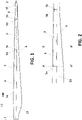
- the blade may comprise, see Figure 1 , a profiled contour formed by a pressure side shell (7) and a suction side shell (8) rigidly joined thereof, further comprising a blade root (1), a blade tip (2), a leading edge (3) and a trailing edge (4) with a chord extending therebetween.
- each shell may comprise at least one electrical connector layer (5) located at a first distance L1 from the blade root (1) and extending from the leading edge (3) towards the trailing edge (4), at least one heating elements layer (6) electrically in contact with the electrical connector layer (5), wherein said heating element layer (6) extending in a longitudinal direction therebetween the blade root (1) and the blade tip (2) and more proximate to the leading edge (3) than to the trailing edge (4).
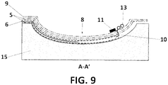
- glass fabric layers (9) are inwardly in contact with the electrical connector layer (5) or with heating elements layer (6) -depending on the arrangement between said layers (5,6) which may be inwardly or alternatively outwardly in contact thereof-- and the blade further comprises a connector component (10) extending transversally through the glass fabric layers (9) and being electrically connected with the electrical connector layer (5) and with a metallic block (11).
- the blade may further comprise power wires (13) extending longitudinally from a power source near the blade root (1) to the connector component (10) being electrically in contact thereof, said power wires (13) located in at least one of the shells (7,8), and wherein the aforementioned metallic blocks (11) are drilled by an inter-connector (12) so that the electrical connector components (10) from each shell (7,8) are electrically connected and the blade is able to be heated by the heating elements layer (9) when electrically fed from the power source
- the aforementioned blade may comprise several embodiments with different combination regarding the respective order of the plurality of aforementioned layers.
- heating elements layer (6) may be applied during the manufacturing and before infusion and curing or after the pressure shell (7) and the suction shell (8) have been rigidly joined.
- FIG. 1 it is shown as example, a blade comprising three heating elements (6) on one shell.
- the first having electrical connectors (5a, 5b), for the second being (5c, 5d) and for the third (5e, 5f).
- One of each electrical connectors for each heating element (6) connected to one power wire (13) .
- Figure 2 shows a partial view of the blade of Figure 1 , showing two cross sections, a first cross section A-A' and a second cross section B-B'.
- the two electrical connectors (5a, 5b) for heating element (6) shall be connected to two different power wires (13) in order to be fed from a power source.
- each shell (7,8) further comprises second glass fabric layers (9) outwardly in contact with the heating elements layer (6) or the electrical connector layer (5).
- the heating elements layer (6) is outwardly in contact with the electrical connector layer (5) during the manufacturing of the blade at cross section A-A'.
- the heating element layer (6) may be inwardly in contact with the electrical connector layer (5).
- the farthest and exterior layer is the heating elements layer (6) in electrical contact with adjacent electrical connector layer (5) inwardly displaced therein.
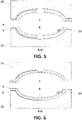
- Figure 5 illustrates the second section B-B' of the blade according to the aforementioned first embodiment. It can be clearly appreciated that the electrical connector layer (5) does not extend along all the longitudinal direction of the blade but rather at the connections at the heating elements layer (6) ends, one of them clearly being section A-A' in FIG.3 . Thus, it is not shown at FIG.5 .
- section B-B' comprises glass fabric layers inwardly and outwardly of the heating element layer (6).
- FIG. 6 it illustrates second section B-B' of the blade according to the aforementioned second embodiment.
- the electrical connector layer (5) does not extend along all the longitudinal direction of the blade but rather at the connections at the heating elements layer (6) ends, one of them clearly being section A-A' in FIG.6 .
- section B-B' comprises glass fabric layers inwardly of the heating element layer (6) farthest exteriorly -closer to the molds (15).
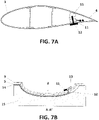
- FIG. 7A it is therein illustrated a cross-sectional side view at section A-A', where it is clearly shown the aforementioned metallic blocks (11) are drilled by an inter-connector (12) so that the electrical connector layer (10) from each shell (7,8) are electrically connected and the blade is able to be heated by the heating elements layer (9) when electrically fed from the power source.
- FIG.7B and FIG.8A it is therein exemplified a third preferred embodiment wherein the heating element layer (6) its not applied during the manufacturing of each shell (7,8). Rather a plastic adhesive tape (14) is applied farthest towards the exterior, and the heating elements layer (6) is applied after the shells (7,8) have been rigidly joined - see FIG.8A --.
- the electrical connection layer (10) which may be electrically connecting the electrical connector layer (5) with the metallic block (11).
- Figure 8B illustrates a fourth embodiment wherein a first heating elements layer (6) is applied during manufacturing extending therebetween the leading edge (3) and the trailing edge (4).
- plastic adhesive tape (14) in the leading edge which may be not in contact with the first heating elements (6) and after the shells (7,8) have been rigidly joined the plastic adhesive tape (14) may be removed and second heating elements layer (6) may be applied therein in the leading edge (3) in electric contact with the electric connector layer (5).
- each shell (7,8) may comprise two electrical connector layers (5) wherein the heating elements layer (6) may be in electrical contact with each electrical connector layers (5) and located therebetween.
- the heating element of the heating elements layer (6) may be carbon fiber with a biaxial structure, ⁇ 45° respect to the blade longitudinal direction, or carbon veil.
- the electrical connector layer (5) comprises a copper or aluminum mesh, or any composite materials with metallic additives or wires.
- Said electrical connectors may be 20-400 mm wide and 50-500 ⁇ m of thickness.
- each shell (7,8) comprises a plurality of electrical connector layers (5a - 5f) extending between the blade root (1) and the blade tip (2) beyond distance L1, wherein each electrical connector layer (5a - 5f) is electrically connected to a corresponding heating element layer (6) and to a connector component (10) which in turn is electrically connected to a metallic block (11) and power wires (13), so that another region of the blade can be heated independently with different heating elements -see FIG 1 --.
- cross section, A-A' of any of the several embodiments can be reproduced a plurality of times along the blade longitudinal direction at every end of the heating elements layer (6).
- the method further comprises the step of connecting the metallic block (11) and the power wires (13) to the connector component (10) before or after the infusion and curing of each shell (7,8).
- the method further comprises the step of applying a heating element layer (6) electrically in contact outwardly or inwardly to the electrical connector layer (5), during the manufacturing of each shell (7,8) and before their infusion and curing.
- the method comprises the step of applying a plastic adhesive tape (14) in a region on the leading edge (3) during the manufacturing of each shell (7,8) and before demolding, and after the shells (7,8) have been rigidly joined together apply a heating elements layer (6) on the region where the plastic adhesive tape (14) was originally placed.
- the metallic blocks (13) may be drilled with the inter-connector (12) so that the electrical connector layers (10) from each shell (7,8) are electrically connected and the blade is able to be heated by the heating elements layer (6) when electrically fed from the power source.
Landscapes
- Engineering & Computer Science (AREA)
- Mechanical Engineering (AREA)
- Chemical & Material Sciences (AREA)
- Life Sciences & Earth Sciences (AREA)
- Sustainable Development (AREA)
- Sustainable Energy (AREA)
- Combustion & Propulsion (AREA)
- General Engineering & Computer Science (AREA)
- Physics & Mathematics (AREA)
- Thermal Sciences (AREA)
- Composite Materials (AREA)
- Resistance Heating (AREA)
- Wind Motors (AREA)
Claims (15)
- Pâle pour un rotor d'une éolienne, comprenant un contour profilé formé par une coque côté pression (7) et une coque côté aspiration (8) assemblées rigidement entre elles, ladite pâle comprenant un pied de pâle (1), une extrémité de pâle (2), un bord d'attaque (3) et un bord de fuite (4) avec une corde s'étendant entre ceux-ci, lesdites coques (7, 8) comprenant :- au moins une couche de connecteur électrique (5) située à une première distance L1 du pied de pâle (1) et s'étendant du bord d'attaque (3) vers le bord de fuite (4),- au moins une couche d'éléments chauffants (6) électriquement en contact avec la couche de connecteur électrique (5), ladite couche d'élément chauffant (6) s'étendant dans une direction longitudinale entre le pied de pâle (1) et l'extrémité de pâle (2) et plus près du bord d'attaque (3) que du bord de fuite (4),- des couches de tissu de verre (9) en contact au moins à l'intérieur avec la couche de connecteur électrique (5) ou avec la couche d'éléments chauffants (6),- un composant de connecteur (10) s'étendant transversalement à travers les couches de tissu de verre (9) et étant électriquement connecté à la couche de connecteur électrique (5) et à un bloc métallique (11),- des fils d'alimentation (13) s'étendant longitudinalement à partir d'une source d'alimentation à côté du pied de pâle (1) jusqu'au composant de connecteur (10), l'un de ces fils d'alimentation (13) étant électriquement en contact avec celui-ci, lesdits fils d'alimentation (13) étant situés dans au moins une des coques (7, 8),dans laquelle les blocs métalliques (11) sont percés par un inter-connecteur (12) de telle manière que les couches de connecteur électrique (5) de chaque coque (7, 8) sont électriquement connectées et la pâle peut être chauffée par la couche d'éléments chauffants (6) lorsqu'elle est alimentée électriquement par la source d'alimentation.
- Pâle d'éolienne selon la revendication 1, dans laquelle chaque coque (7, 8) comprend en outre des deuxièmes couches de tissu de verre (9) extérieurement en contact avec la couche d'éléments chauffants (6) ou la couche de connecteur électrique (5).
- Pâle d'éolienne selon la revendication 1, dans laquelle la couche d'éléments chauffants (6) est en contact à l'extérieur avec la couche de connecteur électrique (5).
- Pâle d'éolienne selon la revendication 1, dans laquelle la couche d'éléments chauffants (6) est en contact à l'intérieur avec la couche de connecteur électrique (5).
- Pâle d'éolienne selon la revendication 4, comprenant une deuxième couche de connecteur électrique (5) électriquement en contact vers l'extérieur avec la couche de connecteur électrique (5) et, facultativement, étant en outre électriquement en contact avec le composant de connecteur (10) .
- Pâle d'éolienne selon la revendication 1, dans laquelle chaque coque (7, 8) comprend en outre une deuxième couche d'élément chauffant (6) électriquement en contact à l'extérieur avec la couche de connecteur électrique (5), ladite deuxième couche d'élément chauffant (6) s'étendant entre le bord d'attaque (3) et le bord de fuite (4) et de façon adjacente à la couche d'élément chauffant (6).
- Pâle d'éolienne selon la revendication 1, dans laquelle chaque coque (7, 8) comprend une pluralité de couches de connecteur électrique s'étendant entre le pied de pâle (1) et l'extrémité de pâle (2) au-delà de la distance L1, dans laquelle chaque couche de connecteur électrique est électriquement connectée à une couche d'élément chauffant correspondante et à un composant de connecteur, qui à son tour est connecté électriquement à un bloc métallique et à l'un des fils d'alimentation, afin qu'une autre région de la pâle puisse être chauffée indépendamment avec des éléments chauffants différents.
- Pâle d'éolienne selon la revendication 1, dans laquelle l'élément chauffant est une fibre de carbone ayant une structure biaxiale, à ± 45° par rapport à la direction longitudinale de la pâle, un voile de carbone ou un quelconque tissu composite incluant des composants conducteurs.
- Pâle d'éolienne selon la revendication 1, dans laquelle le connecteur électrique est un maillage de cuivre ou d'aluminium ou un quelconque matériau composite comprenant des adjuvants ou des fils métalliques.
- Pâle d'éolienne selon la revendication 1, dans laquelle le connecteur électrique a une largeur de 20 à 400 mm et une épaisseur de 50 à 500 µm.
- Procédé de fabrication de la pâle selon les revendications 1 à 10, dans lequel, durant la fabrication de chaque coque (7, 8), le procédé comprend au moins :a) la mise en place d'une couche de connecteur électrique (5) sur un moule ayant le profil de contour de la coque correspondante (7, 8) et la connexion de ladite couche de connecteur électrique (5) au composant de connecteur (10) de celle-ci,b) l'application de couches de tissus de verre (9) de manière à les placer en contact vers l'intérieur ou vers l'extérieur par rapport à ladite couche de connecteur électrique (5), de telle façon que lorsqu'elles sont en contact vers l'extérieur, elles soient placées dans le moule avant la couche de connecteur électrique (5) et lorsqu'elles sont en contact vers l'intérieur, elles soient placées dans le moule après la couche de connecteur électrique (5).
- Procédé de fabrication selon la revendication 11, comprenant l'étape d'installation et/ou de connexion du bloc métallique (11) et des fils d'alimentation (13) au composant de connecteur (10) durant ou après la fabrication de chaque coque (7, 8).
- Procédé de fabrication selon la revendication 11, comprenant une étape d'application d'une couche d'élément chauffant (6) électriquement en contact vers l'extérieur ou vers l'intérieur avec la couche de connecteur électrique (5), pendant la fabrication de chaque coque (7, 8) et avant l'infusion et le durcissement de la coque.
- Procédé de fabrication selon l'une quelconque des revendications 11 à 13, comprenant l'étape d'application d'un ruban adhésif plastique (14) dans une région sur le bord d'attaque (3) durant la fabrication de chaque coque (7, 8) et avant le démoulage, et après que les coques (7, 8) ont été assemblées rigidement, l'application d'une couche d'éléments chauffants (6) sur la région où le ruban adhésif plastique (14) a été initialement placé.
- Procédé de fabrication selon l'une quelconque des revendications 11 à 14, dans lequel après que les coques (7, 8) ont été assemblées rigidement, les blocs métalliques (13) sont percés avec l'inter-connecteur (12).
Priority Applications (4)
| Application Number | Priority Date | Filing Date | Title |
|---|---|---|---|
| EP20380009.9A EP3869035B2 (fr) | 2020-02-21 | 2020-02-21 | Pale pour un rotor d'éolienne et son procédé de fabrication |
| US17/177,537 US20210262449A1 (en) | 2020-02-21 | 2021-02-17 | Blade for a rotor of a wind turbine and manufacturing method thereof |
| CA3109841A CA3109841A1 (fr) | 2020-02-21 | 2021-02-19 | Pale pour un rotor d'eolienne et methode de fabrication connexe |
| CN202110189159.2A CN113294284A (zh) | 2020-02-21 | 2021-02-19 | 用于风力涡轮机的转子的叶片及其制造方法 |
Applications Claiming Priority (1)
| Application Number | Priority Date | Filing Date | Title |
|---|---|---|---|
| EP20380009.9A EP3869035B2 (fr) | 2020-02-21 | 2020-02-21 | Pale pour un rotor d'éolienne et son procédé de fabrication |
Publications (3)
| Publication Number | Publication Date |
|---|---|
| EP3869035A1 EP3869035A1 (fr) | 2021-08-25 |
| EP3869035B1 true EP3869035B1 (fr) | 2022-11-30 |
| EP3869035B2 EP3869035B2 (fr) | 2026-02-11 |
Family
ID=69953929
Family Applications (1)
| Application Number | Title | Priority Date | Filing Date |
|---|---|---|---|
| EP20380009.9A Active EP3869035B2 (fr) | 2020-02-21 | 2020-02-21 | Pale pour un rotor d'éolienne et son procédé de fabrication |
Country Status (4)
| Country | Link |
|---|---|
| US (1) | US20210262449A1 (fr) |
| EP (1) | EP3869035B2 (fr) |
| CN (1) | CN113294284A (fr) |
| CA (1) | CA3109841A1 (fr) |
Families Citing this family (2)
| Publication number | Priority date | Publication date | Assignee | Title |
|---|---|---|---|---|
| EP4108912B1 (fr) * | 2021-06-23 | 2024-11-13 | LM Wind Power A/S | Fabrication d'un élément de protection de bord d'attaque par rognage |
| CN116557239A (zh) * | 2023-05-30 | 2023-08-08 | 湖南博杨新能源科技有限公司 | 一种风力发电机组电热除冰装置 |
Citations (22)
| Publication number | Priority date | Publication date | Assignee | Title |
|---|---|---|---|---|
| EP1187988B1 (fr) | 1999-06-21 | 2003-08-27 | Lm Glasfiber A/S | Pale d'eolienne avec systeme de degivrage et paratonnerre |
| US20070081900A1 (en) | 2005-10-06 | 2007-04-12 | Nordex Energy Gmbh | Method for the production of a leadthrough in a fibre compound material, as well as a rotor blade for a wind energy facility with a leadthrough |
| WO2008101506A2 (fr) | 2007-02-19 | 2008-08-28 | Vestas Wind Systems A/S | Pale d'éolienne et procédé de fabrication d'une telle pale |
| EP1965076A1 (fr) | 2005-12-21 | 2008-09-03 | Mitsubishi Heavy Industries, Ltd. | Dispositif parafoudre de pale d'eolienne |
| WO2011127995A1 (fr) | 2010-04-12 | 2011-10-20 | Siemens Aktiengesellschaft | Fixation d'une garniture chauffante sur une pale d'éolienne |
| EP2420852A1 (fr) | 2010-08-20 | 2012-02-22 | Siemens Aktiengesellschaft | Système de mesure pour conducteur descendant d'une pale d'éolienne |
| EP2497943A1 (fr) | 2011-03-11 | 2012-09-12 | Siemens Aktiengesellschaft | Agencement pour améliorer la surface d'une pale d'éolienne |
| EP2597305A1 (fr) | 2011-11-24 | 2013-05-29 | Nordex Energy GmbH | Pale de rotor d'éolienne dotée d'un élément chauffant et son procédé de fabrication |
| NL2010553C2 (nl) | 2013-04-02 | 2014-10-06 | Composite Technology Ct B V | Blad voor een windmolen, windmolen omvattende een derglijk blad, werkwijze voor het vervaardigen van een blad voor een windmolen, en werkwijze voor het repareren van een met een dergelijke werkwijze vervaardigd blad. |
| WO2015055215A1 (fr) | 2013-10-17 | 2015-04-23 | Vestas Wind Systems A/S | Améliorations se rapportant à des systèmes de protection contre la foudre pour pales d'éolienne |
| WO2015055213A1 (fr) | 2013-10-17 | 2015-04-23 | Vestas Wind Systems A/S | Améliorations se rapportant à des systèmes de protection contre la foudre pour pales d'éolienne |
| WO2015055214A1 (fr) | 2013-10-17 | 2015-04-23 | Vestas Wind Systems A/S | Améliorations concernant des systèmes de protection contre la foudre pour pales d'éolienne |
| WO2015055216A1 (fr) | 2013-10-17 | 2015-04-23 | Vestas Wind Systems A/S | Améliorations apportées à des systèmes de protection contre la foudre pour pales d'éoliennes |
| US20150204311A1 (en) | 2012-08-06 | 2015-07-23 | Wobben Properties Gmbh | Cfrp resistive sheet heating |
| EP2930357A1 (fr) | 2014-04-10 | 2015-10-14 | Nordex Energy GmbH | Pale de rotor d'éolienne dotée d'un récepteur d'atmosphériques |
| EP2110552B1 (fr) | 2008-04-15 | 2015-10-28 | Siemens Aktiengesellschaft | Pale d'éolienne avec un conducteur d'éclairage intégré et son procédé de fabrication |
| EP2649690B1 (fr) | 2011-12-09 | 2016-03-23 | MITSUBISHI HEAVY INDUSTRIES, Ltd. | Pale d'éolienne |
| EP3091228A1 (fr) | 2015-05-08 | 2016-11-09 | Gamesa Innovation & Technology, S.L. | Système de protection contre la foudre pour pales d'éolienne à composants structuraux conducteurs |
| EP3263893A1 (fr) | 2016-06-28 | 2018-01-03 | Greger Nilsson | Pale de rotor de turbine éolienne comprenant un système de chauffage électrique |
| CN108843523A (zh) | 2018-06-21 | 2018-11-20 | 株洲时代新材料科技股份有限公司 | 一种带除冰功能的风力发电涡轮机叶片及其制造方法 |
| EP3604795A1 (fr) | 2018-08-02 | 2020-02-05 | Nordex Energy GmbH | Élément chauffant et lame de rotor d'une éolienne |
| EP3736443A1 (fr) | 2019-05-09 | 2020-11-11 | Siemens Gamesa Renewable Energy A/S | Pale d'éolienne et éolienne |
Family Cites Families (12)
| Publication number | Priority date | Publication date | Assignee | Title |
|---|---|---|---|---|
| GB2477338B (en) * | 2010-01-29 | 2011-12-07 | Gkn Aerospace Services Ltd | Electrothermal heater |
| FI20115536L (fi) * | 2011-05-31 | 2013-03-25 | Teknologian Tutkimuskeskus Vtt Oy | Tuuliturbiinin siipi ja tähän liittyvä valmistusmenetelmä |
| CN102918262A (zh) * | 2011-12-09 | 2013-02-06 | 三菱重工业株式会社 | 风车叶片 |
| JP5675673B2 (ja) * | 2012-02-29 | 2015-02-25 | 三菱重工業株式会社 | 繊維強化プラスチック発熱体および該発熱体を備えた風力発電装置 |
| KR101390310B1 (ko) * | 2012-05-18 | 2014-04-29 | 삼성중공업 주식회사 | 풍력발전기 |
| EP2754891B1 (fr) * | 2013-01-14 | 2017-05-17 | Siemens Aktiengesellschaft | Système de dégivrage de pale de rotor d'éolienne |
| CN105673361B (zh) * | 2015-12-31 | 2018-07-13 | 东方电气风电有限公司 | 风力发电机叶片的融冰加热结构及其制作方法 |
| US10787267B2 (en) * | 2017-05-30 | 2020-09-29 | Bell Helicopter Textron Inc. | Electrical bus arrangement for ice protection systems |
| CN107642465B (zh) * | 2017-10-27 | 2024-07-02 | 刘中威 | 风力发电机组及其叶片化冰装置 |
| CN110195690B (zh) * | 2018-02-27 | 2023-03-24 | 新疆金风科技股份有限公司 | 叶片融冰装置、叶片及风力发电机组 |
| CN208138100U (zh) * | 2018-04-13 | 2018-11-23 | 东方电气风电有限公司 | 一种带导电涂层的风电叶片加热融冰装置的导电接头结构 |
| EP3597911B1 (fr) * | 2018-07-17 | 2021-08-25 | Siemens Gamesa Renewable Energy A/S | Pale de turbine éolienne et éolienne |
-
2020
- 2020-02-21 EP EP20380009.9A patent/EP3869035B2/fr active Active
-
2021
- 2021-02-17 US US17/177,537 patent/US20210262449A1/en not_active Abandoned
- 2021-02-19 CA CA3109841A patent/CA3109841A1/fr active Pending
- 2021-02-19 CN CN202110189159.2A patent/CN113294284A/zh active Pending
Patent Citations (22)
| Publication number | Priority date | Publication date | Assignee | Title |
|---|---|---|---|---|
| EP1187988B1 (fr) | 1999-06-21 | 2003-08-27 | Lm Glasfiber A/S | Pale d'eolienne avec systeme de degivrage et paratonnerre |
| US20070081900A1 (en) | 2005-10-06 | 2007-04-12 | Nordex Energy Gmbh | Method for the production of a leadthrough in a fibre compound material, as well as a rotor blade for a wind energy facility with a leadthrough |
| EP1965076A1 (fr) | 2005-12-21 | 2008-09-03 | Mitsubishi Heavy Industries, Ltd. | Dispositif parafoudre de pale d'eolienne |
| WO2008101506A2 (fr) | 2007-02-19 | 2008-08-28 | Vestas Wind Systems A/S | Pale d'éolienne et procédé de fabrication d'une telle pale |
| EP2110552B1 (fr) | 2008-04-15 | 2015-10-28 | Siemens Aktiengesellschaft | Pale d'éolienne avec un conducteur d'éclairage intégré et son procédé de fabrication |
| WO2011127995A1 (fr) | 2010-04-12 | 2011-10-20 | Siemens Aktiengesellschaft | Fixation d'une garniture chauffante sur une pale d'éolienne |
| EP2420852A1 (fr) | 2010-08-20 | 2012-02-22 | Siemens Aktiengesellschaft | Système de mesure pour conducteur descendant d'une pale d'éolienne |
| EP2497943A1 (fr) | 2011-03-11 | 2012-09-12 | Siemens Aktiengesellschaft | Agencement pour améliorer la surface d'une pale d'éolienne |
| EP2597305A1 (fr) | 2011-11-24 | 2013-05-29 | Nordex Energy GmbH | Pale de rotor d'éolienne dotée d'un élément chauffant et son procédé de fabrication |
| EP2649690B1 (fr) | 2011-12-09 | 2016-03-23 | MITSUBISHI HEAVY INDUSTRIES, Ltd. | Pale d'éolienne |
| US20150204311A1 (en) | 2012-08-06 | 2015-07-23 | Wobben Properties Gmbh | Cfrp resistive sheet heating |
| NL2010553C2 (nl) | 2013-04-02 | 2014-10-06 | Composite Technology Ct B V | Blad voor een windmolen, windmolen omvattende een derglijk blad, werkwijze voor het vervaardigen van een blad voor een windmolen, en werkwijze voor het repareren van een met een dergelijke werkwijze vervaardigd blad. |
| WO2015055214A1 (fr) | 2013-10-17 | 2015-04-23 | Vestas Wind Systems A/S | Améliorations concernant des systèmes de protection contre la foudre pour pales d'éolienne |
| WO2015055216A1 (fr) | 2013-10-17 | 2015-04-23 | Vestas Wind Systems A/S | Améliorations apportées à des systèmes de protection contre la foudre pour pales d'éoliennes |
| WO2015055213A1 (fr) | 2013-10-17 | 2015-04-23 | Vestas Wind Systems A/S | Améliorations se rapportant à des systèmes de protection contre la foudre pour pales d'éolienne |
| WO2015055215A1 (fr) | 2013-10-17 | 2015-04-23 | Vestas Wind Systems A/S | Améliorations se rapportant à des systèmes de protection contre la foudre pour pales d'éolienne |
| EP2930357A1 (fr) | 2014-04-10 | 2015-10-14 | Nordex Energy GmbH | Pale de rotor d'éolienne dotée d'un récepteur d'atmosphériques |
| EP3091228A1 (fr) | 2015-05-08 | 2016-11-09 | Gamesa Innovation & Technology, S.L. | Système de protection contre la foudre pour pales d'éolienne à composants structuraux conducteurs |
| EP3263893A1 (fr) | 2016-06-28 | 2018-01-03 | Greger Nilsson | Pale de rotor de turbine éolienne comprenant un système de chauffage électrique |
| CN108843523A (zh) | 2018-06-21 | 2018-11-20 | 株洲时代新材料科技股份有限公司 | 一种带除冰功能的风力发电涡轮机叶片及其制造方法 |
| EP3604795A1 (fr) | 2018-08-02 | 2020-02-05 | Nordex Energy GmbH | Élément chauffant et lame de rotor d'une éolienne |
| EP3736443A1 (fr) | 2019-05-09 | 2020-11-11 | Siemens Gamesa Renewable Energy A/S | Pale d'éolienne et éolienne |
Also Published As
| Publication number | Publication date |
|---|---|
| CN113294284A (zh) | 2021-08-24 |
| EP3869035A1 (fr) | 2021-08-25 |
| CA3109841A1 (fr) | 2021-08-21 |
| EP3869035B2 (fr) | 2026-02-11 |
| US20210262449A1 (en) | 2021-08-26 |
Similar Documents
| Publication | Publication Date | Title |
|---|---|---|
| US10632573B2 (en) | Wind turbine blade and related method of manufacture | |
| EP2526292B1 (fr) | Fixation d'une natte de chauffage sur un pale d'eolienne | |
| JPH0747400B2 (ja) | 翼構造の除霜装置 | |
| US20130136598A1 (en) | Wind turbine rotor blade having a heating element and a method of making the same | |
| CN105673361A (zh) | 风力发电机叶片的融冰加热结构及其制作方法 | |
| CN103147931A (zh) | 具有电加热元件的风能装置转子叶片 | |
| EP3869035B1 (fr) | Pale pour un rotor d'éolienne et son procédé de fabrication | |
| EP3248867B1 (fr) | Gaine de pales d'hélice | |
| WO2021110225A1 (fr) | Liaison équipotentielle pour pale de rotor d'éolienne | |
| US20240254972A1 (en) | Wind turbine blade having a de-icing system | |
| CN112922792B (zh) | 叶片电热复合膜、叶片、风力发电机组及制造叶片的方法 | |
| CN115151725A (zh) | 用于风力涡轮机的转子叶片的主层压件的雷电保护系统 | |
| CN109322784B (zh) | 一种用于风力发电机组的叶片的前缘构件、叶片及叶轮 | |
| EP4502362A1 (fr) | Pale d'éolienne intégrant un système de protection contre la glace et son procédé de fabrication | |
| CN120303481A (zh) | 具有电热系统的风力涡轮机叶片 | |
| CN110815860B (zh) | 防结冰叶片的制备方法、叶片以及风力发电机组 | |
| US20250043773A1 (en) | Wind turbine blade having an electro-thermal system | |
| EP4397857A1 (fr) | Pale d'éolienne avec système de dégivrage | |
| EP3885266B1 (fr) | Agencement de protection contre la glace dans le sens de la corde résistant aux contraintes élevées | |
| EP3805551A1 (fr) | Pale d'éolienne comportant plusieurs résistances électriques pour le chauffage de la pale | |
| CN121488103A (zh) | 具有加热元件的风力涡轮机叶片壳体 | |
| US12492683B2 (en) | Heating element for an outer surface of a wind turbine rotor blade |
Legal Events
| Date | Code | Title | Description |
|---|---|---|---|
| PUAI | Public reference made under article 153(3) epc to a published international application that has entered the european phase |
Free format text: ORIGINAL CODE: 0009012 |
|
| STAA | Information on the status of an ep patent application or granted ep patent |
Free format text: STATUS: THE APPLICATION HAS BEEN PUBLISHED |
|
| AK | Designated contracting states |
Kind code of ref document: A1 Designated state(s): AL AT BE BG CH CY CZ DE DK EE ES FI FR GB GR HR HU IE IS IT LI LT LU LV MC MK MT NL NO PL PT RO RS SE SI SK SM TR |
|
| STAA | Information on the status of an ep patent application or granted ep patent |
Free format text: STATUS: REQUEST FOR EXAMINATION WAS MADE |
|
| 17P | Request for examination filed |
Effective date: 20220225 |
|
| RBV | Designated contracting states (corrected) |
Designated state(s): AL AT BE BG CH CY CZ DE DK EE ES FI FR GB GR HR HU IE IS IT LI LT LU LV MC MK MT NL NO PL PT RO RS SE SI SK SM TR |
|
| GRAP | Despatch of communication of intention to grant a patent |
Free format text: ORIGINAL CODE: EPIDOSNIGR1 |
|
| STAA | Information on the status of an ep patent application or granted ep patent |
Free format text: STATUS: GRANT OF PATENT IS INTENDED |
|
| RIC1 | Information provided on ipc code assigned before grant |
Ipc: F03D 80/40 20160101AFI20220615BHEP |
|
| INTG | Intention to grant announced |
Effective date: 20220629 |
|
| GRAS | Grant fee paid |
Free format text: ORIGINAL CODE: EPIDOSNIGR3 |
|
| GRAA | (expected) grant |
Free format text: ORIGINAL CODE: 0009210 |
|
| STAA | Information on the status of an ep patent application or granted ep patent |
Free format text: STATUS: THE PATENT HAS BEEN GRANTED |
|
| AK | Designated contracting states |
Kind code of ref document: B1 Designated state(s): AL AT BE BG CH CY CZ DE DK EE ES FI FR GB GR HR HU IE IS IT LI LT LU LV MC MK MT NL NO PL PT RO RS SE SI SK SM TR |
|
| REG | Reference to a national code |
Ref country code: CH Ref legal event code: EP Ref country code: GB Ref legal event code: FG4D |
|
| REG | Reference to a national code |
Ref country code: AT Ref legal event code: REF Ref document number: 1534886 Country of ref document: AT Kind code of ref document: T Effective date: 20221215 Ref country code: DE Ref legal event code: R096 Ref document number: 602020006624 Country of ref document: DE |
|
| REG | Reference to a national code |
Ref country code: IE Ref legal event code: FG4D |
|
| REG | Reference to a national code |
Ref country code: SE Ref legal event code: TRGR |
|
| REG | Reference to a national code |
Ref country code: LT Ref legal event code: MG9D |
|
| REG | Reference to a national code |
Ref country code: NL Ref legal event code: MP Effective date: 20221130 |
|
| PG25 | Lapsed in a contracting state [announced via postgrant information from national office to epo] |
Ref country code: PT Free format text: LAPSE BECAUSE OF FAILURE TO SUBMIT A TRANSLATION OF THE DESCRIPTION OR TO PAY THE FEE WITHIN THE PRESCRIBED TIME-LIMIT Effective date: 20230331 Ref country code: NO Free format text: LAPSE BECAUSE OF FAILURE TO SUBMIT A TRANSLATION OF THE DESCRIPTION OR TO PAY THE FEE WITHIN THE PRESCRIBED TIME-LIMIT Effective date: 20230228 Ref country code: LT Free format text: LAPSE BECAUSE OF FAILURE TO SUBMIT A TRANSLATION OF THE DESCRIPTION OR TO PAY THE FEE WITHIN THE PRESCRIBED TIME-LIMIT Effective date: 20221130 Ref country code: FI Free format text: LAPSE BECAUSE OF FAILURE TO SUBMIT A TRANSLATION OF THE DESCRIPTION OR TO PAY THE FEE WITHIN THE PRESCRIBED TIME-LIMIT Effective date: 20221130 Ref country code: ES Free format text: LAPSE BECAUSE OF FAILURE TO SUBMIT A TRANSLATION OF THE DESCRIPTION OR TO PAY THE FEE WITHIN THE PRESCRIBED TIME-LIMIT Effective date: 20221130 |
|
| REG | Reference to a national code |
Ref country code: AT Ref legal event code: MK05 Ref document number: 1534886 Country of ref document: AT Kind code of ref document: T Effective date: 20221130 |
|
| PG25 | Lapsed in a contracting state [announced via postgrant information from national office to epo] |
Ref country code: RS Free format text: LAPSE BECAUSE OF FAILURE TO SUBMIT A TRANSLATION OF THE DESCRIPTION OR TO PAY THE FEE WITHIN THE PRESCRIBED TIME-LIMIT Effective date: 20221130 Ref country code: PL Free format text: LAPSE BECAUSE OF FAILURE TO SUBMIT A TRANSLATION OF THE DESCRIPTION OR TO PAY THE FEE WITHIN THE PRESCRIBED TIME-LIMIT Effective date: 20221130 Ref country code: LV Free format text: LAPSE BECAUSE OF FAILURE TO SUBMIT A TRANSLATION OF THE DESCRIPTION OR TO PAY THE FEE WITHIN THE PRESCRIBED TIME-LIMIT Effective date: 20221130 Ref country code: IS Free format text: LAPSE BECAUSE OF FAILURE TO SUBMIT A TRANSLATION OF THE DESCRIPTION OR TO PAY THE FEE WITHIN THE PRESCRIBED TIME-LIMIT Effective date: 20230330 Ref country code: HR Free format text: LAPSE BECAUSE OF FAILURE TO SUBMIT A TRANSLATION OF THE DESCRIPTION OR TO PAY THE FEE WITHIN THE PRESCRIBED TIME-LIMIT Effective date: 20221130 Ref country code: GR Free format text: LAPSE BECAUSE OF FAILURE TO SUBMIT A TRANSLATION OF THE DESCRIPTION OR TO PAY THE FEE WITHIN THE PRESCRIBED TIME-LIMIT Effective date: 20230301 |
|
| PG25 | Lapsed in a contracting state [announced via postgrant information from national office to epo] |
Ref country code: NL Free format text: LAPSE BECAUSE OF FAILURE TO SUBMIT A TRANSLATION OF THE DESCRIPTION OR TO PAY THE FEE WITHIN THE PRESCRIBED TIME-LIMIT Effective date: 20221130 |
|
| PG25 | Lapsed in a contracting state [announced via postgrant information from national office to epo] |
Ref country code: SM Free format text: LAPSE BECAUSE OF FAILURE TO SUBMIT A TRANSLATION OF THE DESCRIPTION OR TO PAY THE FEE WITHIN THE PRESCRIBED TIME-LIMIT Effective date: 20221130 Ref country code: RO Free format text: LAPSE BECAUSE OF FAILURE TO SUBMIT A TRANSLATION OF THE DESCRIPTION OR TO PAY THE FEE WITHIN THE PRESCRIBED TIME-LIMIT Effective date: 20221130 Ref country code: EE Free format text: LAPSE BECAUSE OF FAILURE TO SUBMIT A TRANSLATION OF THE DESCRIPTION OR TO PAY THE FEE WITHIN THE PRESCRIBED TIME-LIMIT Effective date: 20221130 Ref country code: DK Free format text: LAPSE BECAUSE OF FAILURE TO SUBMIT A TRANSLATION OF THE DESCRIPTION OR TO PAY THE FEE WITHIN THE PRESCRIBED TIME-LIMIT Effective date: 20221130 Ref country code: CZ Free format text: LAPSE BECAUSE OF FAILURE TO SUBMIT A TRANSLATION OF THE DESCRIPTION OR TO PAY THE FEE WITHIN THE PRESCRIBED TIME-LIMIT Effective date: 20221130 Ref country code: AT Free format text: LAPSE BECAUSE OF FAILURE TO SUBMIT A TRANSLATION OF THE DESCRIPTION OR TO PAY THE FEE WITHIN THE PRESCRIBED TIME-LIMIT Effective date: 20221130 |
|
| REG | Reference to a national code |
Ref country code: DE Ref legal event code: R026 Ref document number: 602020006624 Country of ref document: DE |
|
| PG25 | Lapsed in a contracting state [announced via postgrant information from national office to epo] |
Ref country code: SK Free format text: LAPSE BECAUSE OF FAILURE TO SUBMIT A TRANSLATION OF THE DESCRIPTION OR TO PAY THE FEE WITHIN THE PRESCRIBED TIME-LIMIT Effective date: 20221130 Ref country code: AL Free format text: LAPSE BECAUSE OF FAILURE TO SUBMIT A TRANSLATION OF THE DESCRIPTION OR TO PAY THE FEE WITHIN THE PRESCRIBED TIME-LIMIT Effective date: 20221130 |
|
| PLBI | Opposition filed |
Free format text: ORIGINAL CODE: 0009260 |
|
| PLAX | Notice of opposition and request to file observation + time limit sent |
Free format text: ORIGINAL CODE: EPIDOSNOBS2 |
|
| PG25 | Lapsed in a contracting state [announced via postgrant information from national office to epo] |
Ref country code: MC Free format text: LAPSE BECAUSE OF FAILURE TO SUBMIT A TRANSLATION OF THE DESCRIPTION OR TO PAY THE FEE WITHIN THE PRESCRIBED TIME-LIMIT Effective date: 20221130 |
|
| REG | Reference to a national code |
Ref country code: CH Ref legal event code: PL |
|
| 26 | Opposition filed |
Opponent name: LM WIND POWER A/S Effective date: 20230829 |
|
| REG | Reference to a national code |
Ref country code: BE Ref legal event code: MM Effective date: 20230228 |
|
| PG25 | Lapsed in a contracting state [announced via postgrant information from national office to epo] |
Ref country code: LU Free format text: LAPSE BECAUSE OF NON-PAYMENT OF DUE FEES Effective date: 20230221 Ref country code: LI Free format text: LAPSE BECAUSE OF NON-PAYMENT OF DUE FEES Effective date: 20230228 Ref country code: CH Free format text: LAPSE BECAUSE OF NON-PAYMENT OF DUE FEES Effective date: 20230228 |
|
| PG25 | Lapsed in a contracting state [announced via postgrant information from national office to epo] |
Ref country code: SI Free format text: LAPSE BECAUSE OF FAILURE TO SUBMIT A TRANSLATION OF THE DESCRIPTION OR TO PAY THE FEE WITHIN THE PRESCRIBED TIME-LIMIT Effective date: 20221130 |
|
| REG | Reference to a national code |
Ref country code: IE Ref legal event code: MM4A |
|
| PLBB | Reply of patent proprietor to notice(s) of opposition received |
Free format text: ORIGINAL CODE: EPIDOSNOBS3 |
|
| PG25 | Lapsed in a contracting state [announced via postgrant information from national office to epo] |
Ref country code: IE Free format text: LAPSE BECAUSE OF NON-PAYMENT OF DUE FEES Effective date: 20230221 |
|
| PG25 | Lapsed in a contracting state [announced via postgrant information from national office to epo] |
Ref country code: BE Free format text: LAPSE BECAUSE OF NON-PAYMENT OF DUE FEES Effective date: 20230228 |
|
| PG25 | Lapsed in a contracting state [announced via postgrant information from national office to epo] |
Ref country code: IT Free format text: LAPSE BECAUSE OF FAILURE TO SUBMIT A TRANSLATION OF THE DESCRIPTION OR TO PAY THE FEE WITHIN THE PRESCRIBED TIME-LIMIT Effective date: 20221130 |
|
| PG25 | Lapsed in a contracting state [announced via postgrant information from national office to epo] |
Ref country code: BG Free format text: LAPSE BECAUSE OF FAILURE TO SUBMIT A TRANSLATION OF THE DESCRIPTION OR TO PAY THE FEE WITHIN THE PRESCRIBED TIME-LIMIT Effective date: 20221130 |
|
| PG25 | Lapsed in a contracting state [announced via postgrant information from national office to epo] |
Ref country code: BG Free format text: LAPSE BECAUSE OF FAILURE TO SUBMIT A TRANSLATION OF THE DESCRIPTION OR TO PAY THE FEE WITHIN THE PRESCRIBED TIME-LIMIT Effective date: 20221130 |
|
| PLCK | Communication despatched that opposition was rejected |
Free format text: ORIGINAL CODE: EPIDOSNREJ1 |
|
| PG25 | Lapsed in a contracting state [announced via postgrant information from national office to epo] |
Ref country code: CY Free format text: LAPSE BECAUSE OF FAILURE TO SUBMIT A TRANSLATION OF THE DESCRIPTION OR TO PAY THE FEE WITHIN THE PRESCRIBED TIME-LIMIT; INVALID AB INITIO Effective date: 20200221 |
|
| APBP | Date of receipt of notice of appeal recorded |
Free format text: ORIGINAL CODE: EPIDOSNNOA2O |
|
| PLAO | Information deleted related to despatch of communication that opposition is rejected |
Free format text: ORIGINAL CODE: EPIDOSDREJ1 |
|
| APAH | Appeal reference modified |
Free format text: ORIGINAL CODE: EPIDOSCREFNO |
|
| APAW | Appeal reference deleted |
Free format text: ORIGINAL CODE: EPIDOSDREFNO |
|
| PG25 | Lapsed in a contracting state [announced via postgrant information from national office to epo] |
Ref country code: HU Free format text: LAPSE BECAUSE OF FAILURE TO SUBMIT A TRANSLATION OF THE DESCRIPTION OR TO PAY THE FEE WITHIN THE PRESCRIBED TIME-LIMIT; INVALID AB INITIO Effective date: 20200221 |
|
| APBU | Appeal procedure closed |
Free format text: ORIGINAL CODE: EPIDOSNNOA9O |
|
| PG25 | Lapsed in a contracting state [announced via postgrant information from national office to epo] |
Ref country code: TR Free format text: LAPSE BECAUSE OF FAILURE TO SUBMIT A TRANSLATION OF THE DESCRIPTION OR TO PAY THE FEE WITHIN THE PRESCRIBED TIME-LIMIT Effective date: 20221130 |
|
| PUAH | Patent maintained in amended form |
Free format text: ORIGINAL CODE: 0009272 |
|
| STAA | Information on the status of an ep patent application or granted ep patent |
Free format text: STATUS: PATENT MAINTAINED AS AMENDED |
|
| REG | Reference to a national code |
Ref country code: CH Ref legal event code: M12 Free format text: ST27 STATUS EVENT CODE: U-0-0-M10-M12 (AS PROVIDED BY THE NATIONAL OFFICE) Effective date: 20260114 |
|
| 27A | Patent maintained in amended form |
Effective date: 20260211 |
|
| AK | Designated contracting states |
Kind code of ref document: B2 Designated state(s): AL AT BE BG CH CY CZ DE DK EE ES FI FR GB GR HR HU IE IS IT LI LT LU LV MC MK MT NL NO PL PT RO RS SE SI SK SM TR |
|
| REG | Reference to a national code |
Ref country code: DE Ref legal event code: R102 Ref document number: 602020006624 Country of ref document: DE |
|
| PGFP | Annual fee paid to national office [announced via postgrant information from national office to epo] |
Ref country code: SE Payment date: 20260223 Year of fee payment: 7 |
|
| PGFP | Annual fee paid to national office [announced via postgrant information from national office to epo] |
Ref country code: GB Payment date: 20260223 Year of fee payment: 7 |
|
| PGFP | Annual fee paid to national office [announced via postgrant information from national office to epo] |
Ref country code: DE Payment date: 20250829 Year of fee payment: 7 |
|
| PGFP | Annual fee paid to national office [announced via postgrant information from national office to epo] |
Ref country code: FR Payment date: 20260227 Year of fee payment: 7 |