EP3869080A1 - Récipient sous pression et procédé de fabrication d'un récipient sous pression - Google Patents
Récipient sous pression et procédé de fabrication d'un récipient sous pression Download PDFInfo
- Publication number
- EP3869080A1 EP3869080A1 EP20000268.1A EP20000268A EP3869080A1 EP 3869080 A1 EP3869080 A1 EP 3869080A1 EP 20000268 A EP20000268 A EP 20000268A EP 3869080 A1 EP3869080 A1 EP 3869080A1
- Authority
- EP
- European Patent Office
- Prior art keywords
- inner container
- pressure vessel
- fiber
- plastic
- connecting pieces
- Prior art date
- Legal status (The legal status is an assumption and is not a legal conclusion. Google has not performed a legal analysis and makes no representation as to the accuracy of the status listed.)
- Withdrawn
Links
Images

Classifications
-
- F—MECHANICAL ENGINEERING; LIGHTING; HEATING; WEAPONS; BLASTING
- F17—STORING OR DISTRIBUTING GASES OR LIQUIDS
- F17C—VESSELS FOR CONTAINING OR STORING COMPRESSED, LIQUEFIED OR SOLIDIFIED GASES; FIXED-CAPACITY GAS-HOLDERS; FILLING VESSELS WITH, OR DISCHARGING FROM VESSELS, COMPRESSED, LIQUEFIED, OR SOLIDIFIED GASES
- F17C1/00—Pressure vessels, e.g. gas cylinder, gas tank, replaceable cartridge
- F17C1/02—Pressure vessels, e.g. gas cylinder, gas tank, replaceable cartridge involving reinforcing arrangements
- F17C1/04—Protecting sheathings
- F17C1/06—Protecting sheathings built-up from wound-on bands or filamentary material, e.g. wires
-
- F—MECHANICAL ENGINEERING; LIGHTING; HEATING; WEAPONS; BLASTING
- F17—STORING OR DISTRIBUTING GASES OR LIQUIDS
- F17C—VESSELS FOR CONTAINING OR STORING COMPRESSED, LIQUEFIED OR SOLIDIFIED GASES; FIXED-CAPACITY GAS-HOLDERS; FILLING VESSELS WITH, OR DISCHARGING FROM VESSELS, COMPRESSED, LIQUEFIED, OR SOLIDIFIED GASES
- F17C2201/00—Vessel construction, in particular geometry, arrangement or size
- F17C2201/01—Shape
- F17C2201/0104—Shape cylindrical
- F17C2201/0109—Shape cylindrical with exteriorly curved end-piece
-
- F—MECHANICAL ENGINEERING; LIGHTING; HEATING; WEAPONS; BLASTING
- F17—STORING OR DISTRIBUTING GASES OR LIQUIDS
- F17C—VESSELS FOR CONTAINING OR STORING COMPRESSED, LIQUEFIED OR SOLIDIFIED GASES; FIXED-CAPACITY GAS-HOLDERS; FILLING VESSELS WITH, OR DISCHARGING FROM VESSELS, COMPRESSED, LIQUEFIED, OR SOLIDIFIED GASES
- F17C2201/00—Vessel construction, in particular geometry, arrangement or size
- F17C2201/05—Size
- F17C2201/056—Small (<1 m3)
-
- F—MECHANICAL ENGINEERING; LIGHTING; HEATING; WEAPONS; BLASTING
- F17—STORING OR DISTRIBUTING GASES OR LIQUIDS
- F17C—VESSELS FOR CONTAINING OR STORING COMPRESSED, LIQUEFIED OR SOLIDIFIED GASES; FIXED-CAPACITY GAS-HOLDERS; FILLING VESSELS WITH, OR DISCHARGING FROM VESSELS, COMPRESSED, LIQUEFIED, OR SOLIDIFIED GASES
- F17C2203/00—Vessel construction, in particular walls or details thereof
- F17C2203/06—Materials for walls or layers thereof; Properties or structures of walls or their materials
- F17C2203/0602—Wall structures; Special features thereof
- F17C2203/0604—Liners
-
- F—MECHANICAL ENGINEERING; LIGHTING; HEATING; WEAPONS; BLASTING
- F17—STORING OR DISTRIBUTING GASES OR LIQUIDS
- F17C—VESSELS FOR CONTAINING OR STORING COMPRESSED, LIQUEFIED OR SOLIDIFIED GASES; FIXED-CAPACITY GAS-HOLDERS; FILLING VESSELS WITH, OR DISCHARGING FROM VESSELS, COMPRESSED, LIQUEFIED, OR SOLIDIFIED GASES
- F17C2203/00—Vessel construction, in particular walls or details thereof
- F17C2203/06—Materials for walls or layers thereof; Properties or structures of walls or their materials
- F17C2203/0602—Wall structures; Special features thereof
- F17C2203/0612—Wall structures
- F17C2203/0614—Single wall
- F17C2203/0619—Single wall with two layers
-
- F—MECHANICAL ENGINEERING; LIGHTING; HEATING; WEAPONS; BLASTING
- F17—STORING OR DISTRIBUTING GASES OR LIQUIDS
- F17C—VESSELS FOR CONTAINING OR STORING COMPRESSED, LIQUEFIED OR SOLIDIFIED GASES; FIXED-CAPACITY GAS-HOLDERS; FILLING VESSELS WITH, OR DISCHARGING FROM VESSELS, COMPRESSED, LIQUEFIED, OR SOLIDIFIED GASES
- F17C2203/00—Vessel construction, in particular walls or details thereof
- F17C2203/06—Materials for walls or layers thereof; Properties or structures of walls or their materials
- F17C2203/0634—Materials for walls or layers thereof
- F17C2203/0658—Synthetics
- F17C2203/066—Plastics
-
- F—MECHANICAL ENGINEERING; LIGHTING; HEATING; WEAPONS; BLASTING
- F17—STORING OR DISTRIBUTING GASES OR LIQUIDS
- F17C—VESSELS FOR CONTAINING OR STORING COMPRESSED, LIQUEFIED OR SOLIDIFIED GASES; FIXED-CAPACITY GAS-HOLDERS; FILLING VESSELS WITH, OR DISCHARGING FROM VESSELS, COMPRESSED, LIQUEFIED, OR SOLIDIFIED GASES
- F17C2203/00—Vessel construction, in particular walls or details thereof
- F17C2203/06—Materials for walls or layers thereof; Properties or structures of walls or their materials
- F17C2203/0634—Materials for walls or layers thereof
- F17C2203/0658—Synthetics
- F17C2203/0663—Synthetics in form of fibers or filaments
-
- F—MECHANICAL ENGINEERING; LIGHTING; HEATING; WEAPONS; BLASTING
- F17—STORING OR DISTRIBUTING GASES OR LIQUIDS
- F17C—VESSELS FOR CONTAINING OR STORING COMPRESSED, LIQUEFIED OR SOLIDIFIED GASES; FIXED-CAPACITY GAS-HOLDERS; FILLING VESSELS WITH, OR DISCHARGING FROM VESSELS, COMPRESSED, LIQUEFIED, OR SOLIDIFIED GASES
- F17C2205/00—Vessel construction, in particular mounting arrangements, attachments or identifications means
- F17C2205/03—Fluid connections, filters, valves, closure means or other attachments
- F17C2205/0302—Fittings, valves, filters, or components in connection with the gas storage device
- F17C2205/0305—Bosses, e.g. boss collars
-
- F—MECHANICAL ENGINEERING; LIGHTING; HEATING; WEAPONS; BLASTING
- F17—STORING OR DISTRIBUTING GASES OR LIQUIDS
- F17C—VESSELS FOR CONTAINING OR STORING COMPRESSED, LIQUEFIED OR SOLIDIFIED GASES; FIXED-CAPACITY GAS-HOLDERS; FILLING VESSELS WITH, OR DISCHARGING FROM VESSELS, COMPRESSED, LIQUEFIED, OR SOLIDIFIED GASES
- F17C2223/00—Handled fluid before transfer, i.e. state of fluid when stored in the vessel or before transfer from the vessel
- F17C2223/01—Handled fluid before transfer, i.e. state of fluid when stored in the vessel or before transfer from the vessel characterised by the phase
- F17C2223/0107—Single phase
- F17C2223/0123—Single phase gaseous, e.g. CNG, GNC
-
- F—MECHANICAL ENGINEERING; LIGHTING; HEATING; WEAPONS; BLASTING
- F17—STORING OR DISTRIBUTING GASES OR LIQUIDS
- F17C—VESSELS FOR CONTAINING OR STORING COMPRESSED, LIQUEFIED OR SOLIDIFIED GASES; FIXED-CAPACITY GAS-HOLDERS; FILLING VESSELS WITH, OR DISCHARGING FROM VESSELS, COMPRESSED, LIQUEFIED, OR SOLIDIFIED GASES
- F17C2223/00—Handled fluid before transfer, i.e. state of fluid when stored in the vessel or before transfer from the vessel
- F17C2223/03—Handled fluid before transfer, i.e. state of fluid when stored in the vessel or before transfer from the vessel characterised by the pressure level
- F17C2223/036—Very high pressure (>80 bar)
Definitions
- the invention relates to a pressure vessel and a method for producing a pressure vessel made of plastic for a pressurized, flowable or gaseous medium for pressures of up to 700 bar and above.
- pressure vessels for pressurized, flowable or gaseous media for high pressures are described as composite pressure vessels consisting of a plastic liner with pole pieces or connection flanges with fiber-reinforced reinforcement arranged on the end faces
- a pressure vessel for storing gaseous media which has a wall made of a fiber composite material and a liner made of plastic and a connection flange.
- a section of an outer circumference of the connection flange is designed in a conical shape and interacts with a correspondingly designed support ring on the wall of the liner.
- the cone is oriented in such a way that at the end of the connection flange pointing away from the actual pressure vessel, viewed in the longitudinal extension of the pressure vessel, the outer diameter of the flange is smaller than at its end pointing towards the pressure vessel.
- the wall or the fiber composite material is equipped with a ring-shaped or collar-shaped support ring, which in turn is embodied in a correspondingly conical manner at least in sections on its inwardly facing surface.
- the connection flange can thus be pushed outwards from the inside through the opening formed by the support ring. Due to the conical design of the connection flange and the inner surface of the support ring, a positionally and accurately fitting seat of the connection flange on the support ring is achieved.
- the surfaces of the support ring and the connecting flange which are in direct contact with one another serve at the same time as a sealing surface in order to make the pressure vessel gas-tight even under high pressure.
- the DE 10 2011 012 705 B4 discloses a pressure vessel for storing a fluid having an annular inner port having an inner surface and an outer surface, the inner surface defining a passage adapted to receive a supply device therein.
- the inner port further includes a U-shape with a liner channel formed between the inner surface and the outer surface.
- the pressure vessel further comprises a vessel liner, a portion of which is disposed in the liner channel of the inner connector, and an outer connector that is fixed to the outer surface of the inner connector.
- the outer connector has a neck portion and a shoulder portion.
- the shoulder portion has a tapered shape with a decreasing thickness toward a circumference thereof.
- the outer surface of the inner terminal includes a first coupling element for engaging and fixing the inner terminal with the outer terminal.
- the inner surface of the inner connection comprises a second coupling element which is designed to fix the supply device.
- the neck portion of the outer terminal includes a coupling element that engages the first coupling element of the inner terminal.
- the liner channel of the inner connection and the portion of the container liner arranged in the liner channel of the inner connection extend to a region of the inner connection which is arranged between the first coupling element and the second coupling element of the inner connection.
- the DE 10 2011 116 553 A1 describes an inner container for a pressure vessel made of thermoplastic material, with at least one pole piece provided in a neck area and with a winding made of a fiber material reinforcing the inner container, the inner container being produced by extrusion blow molding, and the pole piece being attached to the blow molding tool when the inner container is formed the inner container is molded.
- the pole piece is at least partially enclosed by the inner container and at the same time connected to the inner container in a form-fitting manner. After completion of the inner container, the pole piece is braced and / or secured from the outside with a counter element against the wall of the container.
- the pole piece has an externally threaded neck which penetrates the opening remaining in the inner container and protrudes therefrom.
- the pole piece is placed on a mandrel-shaped or rod-shaped support element between the opened parts of a blow molding tool and enclosed by a tubular or several web-like hot-melt preforms and pressed with the preform between the parts of the closing blow molding tool be screwed onto the neck of the pole piece, the container wall being clamped in the neck area between the pole piece and the counter element, optionally with the interposition of one or more further parts.
- a pole cap encompassing the inner container from the outside can be provided, which is secured with the counter element.
- the pole piece is molded onto the inner container and secured from the outside by a counter element. Since the pole piece is molded onto the inside of the inner container and secured by a counter element, there is a separating surface between the inner wall and the pole piece, which can lead to leaks in the container.
- the DE 196 31 546 C1 discloses a pressure vessel made of a plastic liner and two neck pieces arranged in the neck area and a winding of a fiber composite material reinforcing the liner, at least one neck piece being designed to accommodate a screw-in valve.
- the liner or inner container can either have been produced by a rotary process, a thermal process or by extrusion blow molding.
- the neck pieces are positively anchored to the liner.
- the neck piece is provided with an annular groove into which the liner material engages in a form-fitting manner.
- a clamping ring is pressed onto the end area of the liner.
- a high-pressure tank which consists of a liner, a release agent layer arranged on a surface of the liner, and a reinforcement layer formed on the release agent layer (30).
- the reinforcement layer comprises a resin and a fiber.
- the thickness of the release agent layer is equal to or smaller than the diameter of the fiber of the reinforcement layer.
- the DE 11 2004 002 795 T5 / WO 2005 093313 A1 relates to a metal nozzle bead which is inserted into a plastic cladding of a composite container.
- the container consists of two hoods produced by an injection molding process and a cylinder part produced by an extrusion process. The two hoods are connected by a thermal welding process with opposite ends of the cylinder part to form a container which is used as a core in a filament winding process.
- carbon fiber impregnated with epoxy resin is wrapped around the cladding and cured to form a composite layer and thereby produce a desired high pressure composite container.
- a metal nozzle bead is arranged in the hoods, which uses both a sealing ring made of an elastic material such as rubber or silicone and a tubular fastening part in the plastic lining of the composite container.
- the metal nozzle bead consists of a cylindrical nozzle head part, which has both a vertical through-hole in its center and an internal thread which is formed on an upper portion of the inner peripheral surface of the vertical through-hole, and a disk-shaped nozzle vane part, which around the outer edge of the lower end of the nozzle head part protrudes outwards.
- the metal nozzle bead also includes a seal device provided on a lower portion of the inner peripheral surface of the through hole.
- the sealing device comprises a sealing ring mounting part holding a sealing ring, an external fastening thread which engages with the fastening part, and a fastening surface for applying a predetermined constant pressure to the fastening part, thus providing a desired sealing effect.
- a sealing ring is placed over the sealing ring assembly part and is pressed together by the fastening part, with which the connection point between the metal nozzle bead and the plastic lining is sealed.
- the sealing ring is compressed by the sealing ring mounting part, whereby it is deformed in a cranked sealing ring seat of the fastening part and with the junction between the Nozzle bead and the fairing comes into close contact. In this way, the sealing ring closes a passage for the escape of gas.
- the disadvantage of this invention consists in the use of a container which consists of a cylindrical central part with hoods welded to it and in the use of a metal nozzle bead which is connected to the hood by injection molding, but by an additional fastening part in connection with that inside the hood arranged thread of the metal nozzle lump and is pressed against the hoods with sealing rings.
- Frequent changes in the load on the pressure vessel, as can occur when filling and emptying the vessel, can lead to leaks due to wear on the sealing rings and fatigue of the welded joints.
- the cost of manufacturing such a container is very high.
- the DE 11 2017 003 239 T5 discloses a pressure vessel comprised of a polymeric impervious liner and a reinforcing layer of composite material formed externally around the impervious liner. At least one hub is coupled to the impermeable liner and the reinforcement layer to provide an opening of the pressure vessel, the impervious liner being connected to the hub by means of an annular polymer-metal bond zone formed as a multi-component cast. An annular connecting zone, the metal hub, is coated by means of a polymeric intermediate layer, which is molded with the metal material of the hub as a multi-component casting.
- the polymeric impermeable lining is molded with the polymeric intermediate layer as a multicomponent casting, the polymeric material of the intermediate layer having an adhesiveness to the metal of the hub which is greater than the adhesiveness of the polymeric material of the impermeable lining to the metal of the hub.
- the pressure vessel is manufactured using the following steps: providing a hub made of a metal material, pre-adhesion of the hub by means of multi-component casting of a polymeric intermediate layer on the metal material of the hub, production of an impermeable lining and multi-component casting of the polymer-impermeable lining with the polymeric intermediate layer, covering with a reinforcing layer, see above that the reinforcement layer after completion of the pressure vessel on the outside impermeable liner and extends around at least a portion of the hub, the polymer material of the intermediate layer having an adhesion to the metal of the hub that is greater than an adhesion of the polymer material of the impermeable liner to the metal of the hub.
- the pressure vessel for storing liquid or gaseous media.
- the pressure vessel comprises a plastic inner container with a neck piece connected to it.
- the neck piece is arranged on the container neck in the region of the container opening and is provided with a support sleeve which at least partially encloses the plastic inner container and the neck piece.
- the neck piece is provided with means for receiving a connection fitting.
- An insert forms at least part of the container neck and a sealing seat for the fitting to be inserted into the neck piece.
- the insert has a collar which is welded and / or glued to the wall of the plastic inner container.
- the wall of the plastic inner container is drawn in conically in the area of the container opening and the collar of the insert is designed to complement it.
- connection element comprises a sleeve-shaped neck section and a shoulder section. Furthermore, the connection element has a through-channel which is at least partially rotationally symmetrical to its longitudinal axis and which is delimited by an inlet opening of the neck section.
- the connection element is connected to an inner surface of the inner container via an outer surface of the shoulder section, so that the inner container is arranged between the shoulder section of the connection element and the support sleeve.
- the pressure vessel comprises a clamping collar which is positively connected to the connection element.
- the clamping sleeve is arranged between the inner container and the support sleeve, so that an axial force exerted on the connection element, directed parallel to the longitudinal axis and in the direction of the inlet opening is at least indirectly transferable to the support sleeve via the clamping sleeve, and a displacement of the inner container in the direction of the inlet opening is counteracted by means of the clamping sleeve.
- the 10 2014 013 249 B4 of the applicant describes a pressure vessel which consists of an inner container with end faces and a collar arranged on one end face and an outer jacket made of fiber-reinforced reinforcement, connecting pieces being arranged between the inner container and the outer jacket at the end faces.
- depressions are arranged, into which the connecting pieces are glued with arched flanges adapted to the curvature of the end faces, with a collar directed inwards into the inner container with an axial bore and one, the external thread of a central part of the domed flange of the connector receiving female threads are arranged.
- connection pieces are also glued in or welded in and do not form a positive connection with the plastic inner container, in which case the high pressure results in leaks and the connection pieces being torn out.
- DE 10 2008 040 967 A1 relates to material-plastic composites as functional parts, the material-plastic composites realizing a direct bond via adhesive and, above all, covalent bonds.
- the material-plastic composites consist of at least one material component and at least one elastic plastic component, the material component being coated with at least one (partially) cross-linked lacquer, its (re) active and / or activatable groups with functional groups or its functional groups have formed covalent bonds with (re-) active and / or activatable groups of the elastic plastic component.
- the object is also achieved by a method for producing material-plastic composites in which a layer of a (partially) crosslinkable lacquer is applied to at least one material component, followed by at least one elastic plastic component at least partially on the lacquer layer by means of a thermal application process is applied.
- the object of the invention is to create a pressure vessel made of plastic which is characterized by a high degree of tightness against pressurized, flowable or gaseous media for pressures of up to 700 bar and beyond with frequent and rapid load changes and by cost-effective production.
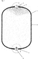
- the object is achieved by a pressure vessel and a method for its production, the pressure vessel being composed of an inner container (1) made of plastic with connecting pieces (5, 6) arranged on the end faces (3, 4) and of an outer casing (2) consists of a fiber-reinforced reinforcement.
- the connecting pieces (5, 6) are molded, in particular rotated, into the end faces (3, 4) of the inner container (3, 4) and into the fiber-reinforced reinforcement of the outer jacket (2).
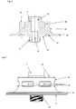
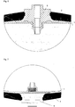
- the connecting pieces (5,6) consist of a hub (7), a cylindrical center piece (10), and a flange (11), the hub (7) having a bore (8) and with an internal thread (9) an external thread (17) arranged at the lower end of the hub (7) reaching into the interior of the inner container (1), the flange (11) with undercuts (12) and anti-rotation locks a (13), and the cylindrical center piece (10) anti-rotation devices b (14) distributed around the circumference and threaded bores (16) arranged on the end face (15) of the cylindrical center piece (10).
- the connecting pieces (5, 6) are designed as a metal insert, which has been pretreated by plasma treatment, flame treatment or laser treatment, and provided with an adhesive for a molding process for plastics, in particular for the rotary sintering process for manufacturing the inner container (1).
- connection pieces (5, 6) with its undercuts (12) and the anti-rotation locks a (13) is rotated into the wall of the inner container (1) by means of rotational sintering on the end faces (3).
- the inner container (1) with the connection piece (5,6) is wrapped with an outer jacket (2) made of a fiber-reinforced reinforcement, the cylindrical middle part (10) with its anti-rotation locks b (14) of the connection pieces (5,6), the outside of the inner container (1) are arranged, are incorporated into the fiber-reinforced reinforcement.
- the inner container consists of cross-linked polyethylenes (PEX), or polyethylenes (PE) or polyamides (PP) or polypropylenes (PP).
- PEX cross-linked polyethylenes
- PE polyethylenes
- PP polyamides
- PP polypropylenes
- An adhesive which forms a convalent bond with a plastic can be used as an adhesion promoter.
- connection pieces (5,6) are made of a stainless steel by machining processes such as turning, milling, drilling and EDM, the connection pieces (5,6) then from a hub (7), a cylindrical center piece (10) and a Flange (11), the hub (7) having a bore (8) carrying an internal thread (9) and an end of the hub (7) with an external thread (17) extending into the interior of the inner container (1) ) are provided, the flange (11) with undercuts (12), anti-rotation devices a (13), the cylindrical center piece (10) with anti-rotation devices b (14) distributed around the circumference and on the end face (15) of the cylindrical center piece (10) arranged threaded bores (16) are provided.
- connection pieces (5, 6) are then pretreated by plasma treatment and provided with an adhesive that forms a convalent bond with plastic and then subjected to a heat treatment at 80 ° C. to remove the solvent contained in the adhesive.
- the connecting pieces (5, 6) are then introduced into a mold for a rotary sintering process and fastened in such a way that the connecting pieces (5, 6) are attached to the end faces (3, 4,) of the inner container (1) during the manufacture of the inner container ( 1) rotated by rotation sintering into the plastic material PEX so that the flange (11) with the undercuts (12) and anti-rotation locks a (13) is embedded in the cross-linked polyethylene (PEX).
- the inner container (1) After the production of the inner container (1) with the connecting pieces (5, 6) on the end faces (3, 4) of the inner container (1), the inner container (1) is wrapped with the outer jacket (2) made of fiber-reinforced reinforcement in such a way that the connecting pieces (5,6) up to the anti-rotation locks b (14) are incorporated into the reinforcement.
Landscapes
- Engineering & Computer Science (AREA)
- Mechanical Engineering (AREA)
- General Engineering & Computer Science (AREA)
- Filling Or Discharging Of Gas Storage Vessels (AREA)
Applications Claiming Priority (1)
| Application Number | Priority Date | Filing Date | Title |
|---|---|---|---|
| DE102020001135.7A DE102020001135B3 (de) | 2020-02-20 | 2020-02-20 | Druckbehälter und Verfahren zur Herstellung eines Druckbehälters |
Publications (1)
| Publication Number | Publication Date |
|---|---|
| EP3869080A1 true EP3869080A1 (fr) | 2021-08-25 |
Family
ID=71994274
Family Applications (1)
| Application Number | Title | Priority Date | Filing Date |
|---|---|---|---|
| EP20000268.1A Withdrawn EP3869080A1 (fr) | 2020-02-20 | 2020-07-29 | Récipient sous pression et procédé de fabrication d'un récipient sous pression |
Country Status (2)
| Country | Link |
|---|---|
| EP (1) | EP3869080A1 (fr) |
| DE (1) | DE102020001135B3 (fr) |
Cited By (3)
| Publication number | Priority date | Publication date | Assignee | Title |
|---|---|---|---|---|
| DE102022203991A1 (de) | 2022-04-25 | 2023-10-26 | Mahle International Gmbh | Tank, insbesondere Wasserstofftank |
| WO2025051312A1 (fr) * | 2023-09-04 | 2025-03-13 | Emano Kunststofftechnik Gmbh | Réservoir tampon et échangeur de chaleur |
| EP4610541A1 (fr) * | 2024-02-29 | 2025-09-03 | A&S Composite s.r.o. | Récipient sous pression en acier inoxydable soudé à paroi mince et son procédé de fabrication |
Families Citing this family (2)
| Publication number | Priority date | Publication date | Assignee | Title |
|---|---|---|---|---|
| DE102022002415B4 (de) | 2022-07-04 | 2024-02-22 | Emano Kunststofftechnik Gmbh | Druckbehälter |
| DE202024000857U1 (de) | 2024-05-02 | 2024-05-29 | Emano Kunststofftechnik Gmbh | Druckbehälter |
Citations (15)
| Publication number | Priority date | Publication date | Assignee | Title |
|---|---|---|---|---|
| DE19631546C1 (de) | 1996-07-24 | 1997-11-13 | Mannesmann Ag | Composite-Druckbehälter zur Speicherung von gasförmigen Medien unter Druck mit einem Liner aus Kunststoff |
| EP0810081A1 (fr) * | 1995-12-04 | 1997-12-03 | Toray Industries, Inc. | Recipient de pression et procede pour le fabriquer |
| KR20030041002A (ko) * | 2001-11-19 | 2003-05-23 | 이중희 | 고압용기용 밀폐식 금속성 노즐 및 금속성 노즐을플라스틱용기에 결착시키는 방법 |
| WO2005093313A1 (fr) | 2004-03-11 | 2005-10-06 | Korea Composite Research Co., Ltd. | Raccord de bis metallique de haute etancheite au gaz pour receptacle composite haute pression |
| DE102008040967A1 (de) | 2008-08-04 | 2010-02-11 | Leibniz-Institut Für Polymerforschung Dresden E.V. | Werkstoff-Kunststoff-Verbunde und Verfahren zu ihrer Herstellung |
| WO2010080948A1 (fr) * | 2009-01-09 | 2010-07-15 | Lincoln Composites | Interface de bossage et de revêtement intérieur de récipient sous pression |
| DE102009014057A1 (de) | 2009-03-20 | 2010-09-23 | Daimler Ag | Druckbehälter mit einem Liner aus Kunststoff |
| WO2011047752A1 (fr) | 2009-10-19 | 2011-04-28 | Kautex Maschinenbau Gmbh | Constitution de col de récipient d'un récipient sous pression |
| WO2011152732A1 (fr) * | 2010-05-31 | 2011-12-08 | Ragasco As | Système d'entrée/sortie pour un récipient composite sous pression |
| DE102011116553A1 (de) | 2011-10-21 | 2013-04-25 | Kautex Textron Gmbh & Co. Kg | Verfahren zur Herstellung eines Verbund-Druckbehälters sowie Verbund-Druckbehälter |
| KR20140066871A (ko) * | 2012-11-23 | 2014-06-03 | 일진복합소재 주식회사 | 압력 용기 |
| WO2015197457A1 (fr) | 2014-06-27 | 2015-12-30 | Kautex Textron Gmbh & Co. Kg | Récipient sous pression |
| DE102011012705B4 (de) | 2010-03-10 | 2017-10-19 | GM Global Technology Operations LLC (n. d. Ges. d. Staates Delaware) | Druckbehälter zum Speichern eines Fluids und Herstellungsverfahren |
| DE102017127853A1 (de) | 2016-12-08 | 2018-06-14 | Toyota Jidosha Kabushiki Kaisha | Hochdrucktank |
| DE112017003239T5 (de) | 2016-06-28 | 2019-03-28 | Faber Industries S.P.A. | Druckbehälter |
Family Cites Families (4)
| Publication number | Priority date | Publication date | Assignee | Title |
|---|---|---|---|---|
| US9316357B2 (en) | 2012-11-23 | 2016-04-19 | ILJIN Composites Co., Ltd. | Pressure vessel |
| EP2941587A1 (fr) | 2013-01-07 | 2015-11-11 | Fibrasynthetica do Brasil Ltda. | Buse destinée à un contenant en plastique et contenant en plastique destiné à des gaz sous pression |
| JP5979446B2 (ja) | 2013-02-04 | 2016-08-24 | 豊田合成株式会社 | 圧力容器 |
| DE102014013249B4 (de) | 2014-09-08 | 2017-04-27 | Emano Kunststofftechnik Gmbh | Druckbehälter |
-
2020
- 2020-02-20 DE DE102020001135.7A patent/DE102020001135B3/de active Active
- 2020-07-29 EP EP20000268.1A patent/EP3869080A1/fr not_active Withdrawn
Patent Citations (16)
| Publication number | Priority date | Publication date | Assignee | Title |
|---|---|---|---|---|
| EP0810081A1 (fr) * | 1995-12-04 | 1997-12-03 | Toray Industries, Inc. | Recipient de pression et procede pour le fabriquer |
| DE19631546C1 (de) | 1996-07-24 | 1997-11-13 | Mannesmann Ag | Composite-Druckbehälter zur Speicherung von gasförmigen Medien unter Druck mit einem Liner aus Kunststoff |
| KR20030041002A (ko) * | 2001-11-19 | 2003-05-23 | 이중희 | 고압용기용 밀폐식 금속성 노즐 및 금속성 노즐을플라스틱용기에 결착시키는 방법 |
| WO2005093313A1 (fr) | 2004-03-11 | 2005-10-06 | Korea Composite Research Co., Ltd. | Raccord de bis metallique de haute etancheite au gaz pour receptacle composite haute pression |
| DE112004002795T5 (de) | 2004-03-11 | 2006-12-28 | Korea Composite Research Co., Ltd. | Hochgradig gasdichter metallischer Düsenwulst für Hochdruck-Verbundstoffbehälter |
| DE102008040967A1 (de) | 2008-08-04 | 2010-02-11 | Leibniz-Institut Für Polymerforschung Dresden E.V. | Werkstoff-Kunststoff-Verbunde und Verfahren zu ihrer Herstellung |
| WO2010080948A1 (fr) * | 2009-01-09 | 2010-07-15 | Lincoln Composites | Interface de bossage et de revêtement intérieur de récipient sous pression |
| DE102009014057A1 (de) | 2009-03-20 | 2010-09-23 | Daimler Ag | Druckbehälter mit einem Liner aus Kunststoff |
| WO2011047752A1 (fr) | 2009-10-19 | 2011-04-28 | Kautex Maschinenbau Gmbh | Constitution de col de récipient d'un récipient sous pression |
| DE102011012705B4 (de) | 2010-03-10 | 2017-10-19 | GM Global Technology Operations LLC (n. d. Ges. d. Staates Delaware) | Druckbehälter zum Speichern eines Fluids und Herstellungsverfahren |
| WO2011152732A1 (fr) * | 2010-05-31 | 2011-12-08 | Ragasco As | Système d'entrée/sortie pour un récipient composite sous pression |
| DE102011116553A1 (de) | 2011-10-21 | 2013-04-25 | Kautex Textron Gmbh & Co. Kg | Verfahren zur Herstellung eines Verbund-Druckbehälters sowie Verbund-Druckbehälter |
| KR20140066871A (ko) * | 2012-11-23 | 2014-06-03 | 일진복합소재 주식회사 | 압력 용기 |
| WO2015197457A1 (fr) | 2014-06-27 | 2015-12-30 | Kautex Textron Gmbh & Co. Kg | Récipient sous pression |
| DE112017003239T5 (de) | 2016-06-28 | 2019-03-28 | Faber Industries S.P.A. | Druckbehälter |
| DE102017127853A1 (de) | 2016-12-08 | 2018-06-14 | Toyota Jidosha Kabushiki Kaisha | Hochdrucktank |
Cited By (3)
| Publication number | Priority date | Publication date | Assignee | Title |
|---|---|---|---|---|
| DE102022203991A1 (de) | 2022-04-25 | 2023-10-26 | Mahle International Gmbh | Tank, insbesondere Wasserstofftank |
| WO2025051312A1 (fr) * | 2023-09-04 | 2025-03-13 | Emano Kunststofftechnik Gmbh | Réservoir tampon et échangeur de chaleur |
| EP4610541A1 (fr) * | 2024-02-29 | 2025-09-03 | A&S Composite s.r.o. | Récipient sous pression en acier inoxydable soudé à paroi mince et son procédé de fabrication |
Also Published As
| Publication number | Publication date |
|---|---|
| DE102020001135B3 (de) | 2021-08-26 |
Similar Documents
| Publication | Publication Date | Title |
|---|---|---|
| DE102020001135B3 (de) | Druckbehälter und Verfahren zur Herstellung eines Druckbehälters | |
| EP2491294B1 (fr) | Constitution de col de récipient d'un récipient sous pression | |
| DE102018009829B4 (de) | Druckbehälter und Verfahren zur Herstellung des Druckbehälters | |
| DE102011103801B4 (de) | Verfahren und Formwerkzeug zum Bilden eines Behälters | |
| DE19631546C1 (de) | Composite-Druckbehälter zur Speicherung von gasförmigen Medien unter Druck mit einem Liner aus Kunststoff | |
| DE102010049838B4 (de) | Ansatzrohr für ein Gefäß sowie Druckgefäß mit solch einem Ansatzrohr | |
| EP1029195B1 (fr) | Reservoir a pression composite muni d'un revetement en plastique, servant a stocker des milieux gazeux sous pression | |
| DE112004002795T5 (de) | Hochgradig gasdichter metallischer Düsenwulst für Hochdruck-Verbundstoffbehälter | |
| DE102014009342B4 (de) | Druckbehälter | |
| DE102014009343B4 (de) | Druckbehälter | |
| DE2152123C3 (de) | Druckbehälter | |
| DE10000705A1 (de) | Druckbehälter zur Speicherung von flüssigen und/oder gasförmigen Medien unter Druck bestehend aus einem Kunststoff-Kernbehälter der mit faserverstärkten Kunststoffen verstärkt ist und Verfahren zu dessen Herstellung | |
| DE102010023386A1 (de) | Druckbehälter | |
| DE102014009341B4 (de) | Druckbehälter | |
| DE202020000706U1 (de) | Druckbehälter | |
| DE102014013249B4 (de) | Druckbehälter | |
| DE102021107165B4 (de) | Endboss-Abdichtung | |
| DE2248589A1 (de) | Elektrisch isolierende rohrkupplung | |
| WO2023088943A1 (fr) | Procédé de soufflage avec pièce de raccordement insérée | |
| DE202014007319U1 (de) | Druckbehälter | |
| DE202018005823U1 (de) | Druckbehälter | |
| DE102016210146B4 (de) | Vorrichtung zur Kantenversiegelung innerhalb mindestens einer Durchbrechung, die infolge eines Trennverfahrens in einem Bauteil aus Faserverbundwerkstoff ausgebildet worden ist | |
| DE102019130278B4 (de) | Verfahren zur Herstellung eines Drucktanks für die Speicherung von Brennstoff in einem Kraftfahrzeug und hiermit hergestellter Drucktank (II) | |
| DE10348820B3 (de) | Verfahren und Vorrichtung zum Herstellen von mehrschichtigen rohrförmigen Bauteilen | |
| EP1058045B1 (fr) | Raccord pour tuyaux |
Legal Events
| Date | Code | Title | Description |
|---|---|---|---|
| PUAI | Public reference made under article 153(3) epc to a published international application that has entered the european phase |
Free format text: ORIGINAL CODE: 0009012 |
|
| STAA | Information on the status of an ep patent application or granted ep patent |
Free format text: STATUS: REQUEST FOR EXAMINATION WAS MADE |
|
| 17P | Request for examination filed |
Effective date: 20200804 |
|
| AK | Designated contracting states |
Kind code of ref document: A1 Designated state(s): AL AT BE BG CH CY CZ DE DK EE ES FI FR GB GR HR HU IE IS IT LI LT LU LV MC MK MT NL NO PL PT RO RS SE SI SK SM TR |
|
| STAA | Information on the status of an ep patent application or granted ep patent |
Free format text: STATUS: EXAMINATION IS IN PROGRESS |
|
| 17Q | First examination report despatched |
Effective date: 20230331 |
|
| GRAP | Despatch of communication of intention to grant a patent |
Free format text: ORIGINAL CODE: EPIDOSNIGR1 |
|
| STAA | Information on the status of an ep patent application or granted ep patent |
Free format text: STATUS: GRANT OF PATENT IS INTENDED |
|
| INTG | Intention to grant announced |
Effective date: 20250714 |
|
| STAA | Information on the status of an ep patent application or granted ep patent |
Free format text: STATUS: THE APPLICATION IS DEEMED TO BE WITHDRAWN |
|
| 18D | Application deemed to be withdrawn |
Effective date: 20251115 |