EP3869209B1 - Dispositif et procédé de mesure de résistance d'isolation - Google Patents
Dispositif et procédé de mesure de résistance d'isolation Download PDFInfo
- Publication number
- EP3869209B1 EP3869209B1 EP19907369.3A EP19907369A EP3869209B1 EP 3869209 B1 EP3869209 B1 EP 3869209B1 EP 19907369 A EP19907369 A EP 19907369A EP 3869209 B1 EP3869209 B1 EP 3869209B1
- Authority
- EP
- European Patent Office
- Prior art keywords
- insulation resistance
- unit
- resistance
- resistance value
- switch
- Prior art date
- Legal status (The legal status is an assumption and is not a legal conclusion. Google has not performed a legal analysis and makes no representation as to the accuracy of the status listed.)
- Active
Links
Images






Classifications
-
- G—PHYSICS
- G01—MEASURING; TESTING
- G01R—MEASURING ELECTRIC VARIABLES; MEASURING MAGNETIC VARIABLES
- G01R31/00—Arrangements for testing electric properties; Arrangements for locating electric faults; Arrangements for electrical testing characterised by what is being tested not provided for elsewhere
- G01R31/36—Arrangements for testing, measuring or monitoring the electrical condition of accumulators or electric batteries, e.g. capacity or state of charge [SoC]
- G01R31/382—Arrangements for monitoring battery or accumulator variables, e.g. SoC
- G01R31/3842—Arrangements for monitoring battery or accumulator variables, e.g. SoC combining voltage and current measurements
-
- G—PHYSICS
- G01—MEASURING; TESTING
- G01R—MEASURING ELECTRIC VARIABLES; MEASURING MAGNETIC VARIABLES
- G01R31/00—Arrangements for testing electric properties; Arrangements for locating electric faults; Arrangements for electrical testing characterised by what is being tested not provided for elsewhere
- G01R31/36—Arrangements for testing, measuring or monitoring the electrical condition of accumulators or electric batteries, e.g. capacity or state of charge [SoC]
- G01R31/389—Measuring internal impedance, internal conductance or related variables
-
- G—PHYSICS
- G01—MEASURING; TESTING
- G01R—MEASURING ELECTRIC VARIABLES; MEASURING MAGNETIC VARIABLES
- G01R27/00—Arrangements for measuring resistance, reactance, impedance, or electric characteristics derived therefrom
- G01R27/02—Measuring real or complex resistance, reactance, impedance, or other two-pole characteristics derived therefrom, e.g. time constant
- G01R27/025—Measuring very high resistances, e.g. isolation resistances, i.e. megohm-meters
-
- G—PHYSICS
- G01—MEASURING; TESTING
- G01R—MEASURING ELECTRIC VARIABLES; MEASURING MAGNETIC VARIABLES
- G01R27/00—Arrangements for measuring resistance, reactance, impedance, or electric characteristics derived therefrom
- G01R27/02—Measuring real or complex resistance, reactance, impedance, or other two-pole characteristics derived therefrom, e.g. time constant
- G01R27/14—Measuring resistance by measuring current or voltage obtained from a reference source
-
- G—PHYSICS
- G01—MEASURING; TESTING
- G01R—MEASURING ELECTRIC VARIABLES; MEASURING MAGNETIC VARIABLES
- G01R27/00—Arrangements for measuring resistance, reactance, impedance, or electric characteristics derived therefrom
- G01R27/02—Measuring real or complex resistance, reactance, impedance, or other two-pole characteristics derived therefrom, e.g. time constant
- G01R27/16—Measuring impedance of element or network through which a current is passing from another source, e.g. cable, power line
- G01R27/18—Measuring resistance to earth, i.e. line to ground
-
- G—PHYSICS
- G01—MEASURING; TESTING
- G01R—MEASURING ELECTRIC VARIABLES; MEASURING MAGNETIC VARIABLES
- G01R31/00—Arrangements for testing electric properties; Arrangements for locating electric faults; Arrangements for electrical testing characterised by what is being tested not provided for elsewhere
- G01R31/36—Arrangements for testing, measuring or monitoring the electrical condition of accumulators or electric batteries, e.g. capacity or state of charge [SoC]
-
- G—PHYSICS
- G01—MEASURING; TESTING
- G01R—MEASURING ELECTRIC VARIABLES; MEASURING MAGNETIC VARIABLES
- G01R31/00—Arrangements for testing electric properties; Arrangements for locating electric faults; Arrangements for electrical testing characterised by what is being tested not provided for elsewhere
- G01R31/36—Arrangements for testing, measuring or monitoring the electrical condition of accumulators or electric batteries, e.g. capacity or state of charge [SoC]
- G01R31/3644—Constructional arrangements
- G01R31/3646—Constructional arrangements for indicating electrical conditions or variables, e.g. visual or audible indicators
-
- G—PHYSICS
- G01—MEASURING; TESTING
- G01R—MEASURING ELECTRIC VARIABLES; MEASURING MAGNETIC VARIABLES
- G01R31/00—Arrangements for testing electric properties; Arrangements for locating electric faults; Arrangements for electrical testing characterised by what is being tested not provided for elsewhere
- G01R31/36—Arrangements for testing, measuring or monitoring the electrical condition of accumulators or electric batteries, e.g. capacity or state of charge [SoC]
- G01R31/3644—Constructional arrangements
- G01R31/3648—Constructional arrangements comprising digital calculation means, e.g. for performing an algorithm
-
- G—PHYSICS
- G01—MEASURING; TESTING
- G01R—MEASURING ELECTRIC VARIABLES; MEASURING MAGNETIC VARIABLES
- G01R31/00—Arrangements for testing electric properties; Arrangements for locating electric faults; Arrangements for electrical testing characterised by what is being tested not provided for elsewhere
- G01R31/36—Arrangements for testing, measuring or monitoring the electrical condition of accumulators or electric batteries, e.g. capacity or state of charge [SoC]
- G01R31/382—Arrangements for monitoring battery or accumulator variables, e.g. SoC
- G01R31/3835—Arrangements for monitoring battery or accumulator variables, e.g. SoC involving only voltage measurements
-
- G—PHYSICS
- G01—MEASURING; TESTING
- G01R—MEASURING ELECTRIC VARIABLES; MEASURING MAGNETIC VARIABLES
- G01R31/00—Arrangements for testing electric properties; Arrangements for locating electric faults; Arrangements for electrical testing characterised by what is being tested not provided for elsewhere
- G01R31/36—Arrangements for testing, measuring or monitoring the electrical condition of accumulators or electric batteries, e.g. capacity or state of charge [SoC]
- G01R31/385—Arrangements for measuring battery or accumulator variables
-
- G—PHYSICS
- G01—MEASURING; TESTING
- G01R—MEASURING ELECTRIC VARIABLES; MEASURING MAGNETIC VARIABLES
- G01R31/00—Arrangements for testing electric properties; Arrangements for locating electric faults; Arrangements for electrical testing characterised by what is being tested not provided for elsewhere
- G01R31/50—Testing of electric apparatus, lines, cables or components for short-circuits, continuity, leakage current or incorrect line connections
- G01R31/52—Testing for short-circuits, leakage current or ground faults
-
- H—ELECTRICITY
- H01—ELECTRIC ELEMENTS
- H01M—PROCESSES OR MEANS, e.g. BATTERIES, FOR THE DIRECT CONVERSION OF CHEMICAL ENERGY INTO ELECTRICAL ENERGY
- H01M10/00—Secondary cells; Manufacture thereof
- H01M10/42—Methods or arrangements for servicing or maintenance of secondary cells or secondary half-cells
- H01M10/425—Structural combination with electronic components, e.g. electronic circuits integrated to the outside of the casing
-
- H—ELECTRICITY
- H01—ELECTRIC ELEMENTS
- H01M—PROCESSES OR MEANS, e.g. BATTERIES, FOR THE DIRECT CONVERSION OF CHEMICAL ENERGY INTO ELECTRICAL ENERGY
- H01M10/00—Secondary cells; Manufacture thereof
- H01M10/42—Methods or arrangements for servicing or maintenance of secondary cells or secondary half-cells
- H01M10/48—Accumulators combined with arrangements for measuring, testing or indicating the condition of cells, e.g. the level or density of the electrolyte
-
- H—ELECTRICITY
- H01—ELECTRIC ELEMENTS
- H01M—PROCESSES OR MEANS, e.g. BATTERIES, FOR THE DIRECT CONVERSION OF CHEMICAL ENERGY INTO ELECTRICAL ENERGY
- H01M10/00—Secondary cells; Manufacture thereof
- H01M10/42—Methods or arrangements for servicing or maintenance of secondary cells or secondary half-cells
- H01M10/425—Structural combination with electronic components, e.g. electronic circuits integrated to the outside of the casing
- H01M2010/4271—Battery management systems including electronic circuits, e.g. control of current or voltage to keep battery in healthy state, cell balancing
-
- Y—GENERAL TAGGING OF NEW TECHNOLOGICAL DEVELOPMENTS; GENERAL TAGGING OF CROSS-SECTIONAL TECHNOLOGIES SPANNING OVER SEVERAL SECTIONS OF THE IPC; TECHNICAL SUBJECTS COVERED BY FORMER USPC CROSS-REFERENCE ART COLLECTIONS [XRACs] AND DIGESTS
- Y02—TECHNOLOGIES OR APPLICATIONS FOR MITIGATION OR ADAPTATION AGAINST CLIMATE CHANGE
- Y02E—REDUCTION OF GREENHOUSE GAS [GHG] EMISSIONS, RELATED TO ENERGY GENERATION, TRANSMISSION OR DISTRIBUTION
- Y02E60/00—Enabling technologies; Technologies with a potential or indirect contribution to GHG emissions mitigation
- Y02E60/10—Energy storage using batteries
Definitions
- the present invention relates to an apparatus and a method for measuring an insulation resistance of a battery.
- the distribution resistor is alternately connected to either of the battery negative electrode and positive electrode with reference to the ground (e.g., chassis), and the insulation resistance value was calculated from the measured distribution voltage value.
- the measurement range within the allowable error range is limited based on- a designed distribution resistance value, for example, as in the case where the actual insulation resistance value is greater than the sum of pre-designed distribution resistance values at the measurement terminals of the battery's negative electrode or positive electrode, the calculated insulation resistance value is out of the measurement range within the error range, so that there was a problem of low measurement accuracy.
- CN 108303588 A relates to a DC system insulation monitoring device that is based on an unbalanced electric bridge, wherein four resistances R1-R4 are controlled by four corresponding switches KG1-KK4.
- CN 103033729 A relates to an insulation detection circuit for a battery box wherein a multiplexer selectively forwards differential voltages across resistors of the insulation detection circuit.
- CN 108334296 A relates to an on-line insulation resistance detection device wherein branches featuring multiple resistors are selectively controlled via corresponding switches.
- KR 2010-0048060 A relates to a resistance measuring device that protects an internal circuit from an electric/magnetic field and improves the selection range for insulation resistance in a dual-source bridge method by applying the leakage effect of the bridge circuit.
- the present invention has been made to solve the above problems, and an object of the present invention is to provide an insulation resistance measuring apparatus and method which can prevent the measurement accuracy from being lowered by calculating the insulation resistance in a measurement range within an error range corresponding to an actual insulation resistance value when measuring an insulation resistance of a battery.
- An insulation resistance measurement apparatus includes: a first resistance unit having a first end connected to an positive electrode of a battery and a second end connected to a ground, wherein the first resistance unit is variably controllable between having a first resistance value or a second resistance value greater than the first resistance value; a second resistance unit having a first end connected to a negative electrode of the battery and a second end connected to the ground, wherein the second resistance unit is variably controllable between having a third resistance value or a fourth resistance value greater than the third resistance value; a voltage measurement unit configured to measure a voltage either or both the first resistance unit or the second resistance unit; and an insulation resistance calculation unit configured to calculate a first insulation resistance value between the positive electrode of the battery and the ground and a second insulation resistance value between the negative electrode of the battery and the ground based on the first resistance value, the second resistance value, the third resistance value, the fourth resistance value and the voltage measured by the voltage measurement unit.
- the insulation resistance measurement apparatus further includes a voltage distribution unit connected in parallel with the first resistance unit or the second resistance unit, wherein the voltage distribution unit includes a plurality of resistors connected in series.
- the voltage measured by the voltage distribution unit may be a voltage measured across some of the plurality of resistors of the voltage distribution unit.
- the insulation resistance calculation unit has a first insulation resistance measurement mode and a second insulation resistance measurement mode, wherein the first insulation resistance measurement mode has a lower error rate than the second insulation resistance measurement mode in a first measurement range, and wherein the second insulation resistance measurement mode has a lower error rate than the first insulation resistance measurement mode in a second measurement range, and is configured to calculate the first and second insulation resistance values based on the first resistance value and the third resistance value in the first insulation resistance measurement mode, and calculate the first and second insulation resistance values based on the second resistance value and the fourth resistance value in the second insulation resistance measurement mode.
- the insulation resistance calculation unit may determine whether the first insulation resistance value is within the first or second measurement range,; and calculate a first actual insulation resistance value in whichever measurement mode has the lower error rate in the determined first or second measurement range that the first insulation resistance value is within, and for the second insulation resistance value, the insulation resistance calculation unit may determine whether the second insulation resistance value is within the first or second measurement range; and calculate a second actual insulation resistance value in whichever measurement mode has the lower error rate in the determined first or second measurement range that the second insulation resistance value is within.
- the first resistance unit may include a first resistance value unit that is ON/OFF controlled by a first switch and a second resistance value unit that is ON/OFF controlled by a second switch, wherein the first and second resistance value units are connected in parallel between the positive electrode of the battery and the ground.
- the second resistance unit may include a third resistance value unit that is ON/OFF controlled by a third switch and a fourth resistance value unit that is ON/OFF controlled by a fourth switch, wherein the third and fourth resistance value units are connected in parallel between the negative electrode of the battery and the ground.
- the first resistance unit may include a first variable resistance unit that is changeable between the first resistance value and the second resistance value based on ON/OFF control by a first switch, wherein the first variable resistance unit is between the positive electrode of the battery and the ground.
- the second resistance unit may include a second variable resistance unit that is changeable between the third resistance value and the fourth resistance value based on ON/OFF control by a second switch, wherein the second variable resistance unit is between the negative electrode of the battery and the ground.
- a switching unit may be configured to, when the first switch or the second switch of the first resistance unit is ON, control the third switch and the fourth switch of the second resistance unit to be OFF. In some examples, a switching unit may be configured to, when the third switch or the fourth switch of the second resistance unit is ON, control the first switch and the second switch of the first resistance unit to be OFF.
- the insulation resistance calculation unit is configured to calculate the first and second insulation resistance values based on the voltage measured across some of the plurality resistors of the voltage distribution unit when the first switch is ON and the second, third and fourth switches are OFF and the voltage measured across some of the plurality of resistors of the voltage distribution unit when the third switch is ON and the first, second and fourth switches are OFF.
- the insulation resistance calculation unit is configured to calculate the first and second insulation resistance values based on the voltage measured across some of the plurality of resistors of the voltage distribution unit when the second switch is ON and the first, third, and fourth switches are OFF and the voltage measured across some of the plurality of resistors of the voltage distribution unit when the fourth switch is ON and the first, second and third switches are OFF.
- the first, second, third and fourth resistance values vary according to the battery or according to a device in which the battery is mounted.
- the voltage distribution unit further includes a fifth switch connected in series with the plurality of resistors and configured to be ON/OFF controlled.
- the battery is a battery rack
- the ground is a chassis of the battery rack.
- an insulation resistance measurement method and performed using one of a plurality of given insulation resistance measurement modes, wherein each respective insulation resistance measurement mode corresponds to a respective measurement range for which an insulation resistance measurement error rate within a respective measurement range is lower than insulation resistance measurement error rates for other ones of the plurality of insulation resistance measurement modes within the respective measurement range includes: calculating a first insulation resistance value between an positive electrode of the battery and a ground and a second insulation resistance value between a negative electrode of the battery and the ground by each insulation resistance measurement mode; determining, which of the respective measurement ranges corresponds to each of the first and second insulation resistance values; and determining an actual insulation resistance value using the respective insulation resistance measurement mode for which the insulation resistance measurement error rate within the determined measurement range is lowest.
- the present invention when measuring the insulation resistance of the battery, it is possible to prevent the measurement accuracy from being lowered by calculating the insulation resistance in a measurement range within an error range corresponding to the actual insulation resistance value. This allows more accurate insulation resistance values to be measured and reported when the battery system is diagnosed.
- FIG. 1 is a block diagram showing the configuration of a battery rack.
- a battery rack R that can be applied to a high voltage battery system includes a battery C capable of charging and discharging in which one or more battery modules (e.g., battery packs) are connected in series or in parallel, a switching unit 2 connected in series to the + terminal (positive electrode) side or the - terminal (negative electrode) side of the battery C to control the charge/discharge current flow of the battery C, and a battery management system 3 (hereinafter also referred to as BMS) that monitors the voltage, current, temperature, etc. of the battery and controls and manages it to prevent overcharge and overdischarge.
- BMS battery management system 3
- the switching unit 2 is a switching element for controlling the current flow for the charging or discharging of the battery C, and may be a configuration that is essentially provided for the operation of the battery rack R.
- the BMS 3 can monitor voltage, current, temperature, and the like as the state of the battery C.
- the BMS 3 may include a circuit that receives a value obtained by measuring various parameters such as voltage, current, and temperature, and performs a process of the received value.
- the battery rack R is provided in the chassis 4 as a housing, and the chassis 4 is grounded.
- Each of the components of the battery rack R that is, the battery C, the switching unit 2, the BMS 3, and the chassis 4, is designed to be insulated therebetween, so that an insulation resistance exists between the battery and the chassis.
- FIG. 2 is a block diagram showing a configuration of an insulation resistance measurement apparatus according to an embodiment of the present invention.
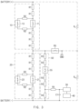
- FIG. 3 is a diagram schematically illustrating a circuit configuration of an insulation resistance measurement apparatus according to an embodiment of the present invention.
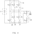
- FIG. 4 is an equivalent circuit of FIG. 3 .
- the insulation resistance measurement apparatus may include a first resistance unit 10, a second resistance unit 20, a voltage measurement unit 30, and an insulation resistance calculation unit 40.
- the first resistance unit 10 has a configuration in which one end is connected to the positive electrode of the battery C and the other end is connected to the ground, and may optionally have a first resistance value or a second resistance value greater than the first resistance value under control.
- the first resistance unit 10 may have a circuit configuration in which the first resistance value unit that is ON/OFF controlled by the first switch 11 and the second resistance value unit that is ON/OFF controlled by the second switch 13 are connected in parallel between the positive electrode of the battery C and the ground.
- the first switch 11 and the second switch 13 may be controlled by an insulation resistance calculation unit 40.
- the first resistance unit 10 may have a first resistance value or a second resistance value selectively by ON/OFF control of the first switch 11 and the second switch 13.
- the first resistance value unit may be a resistance unit having a first resistance value, and may include, for example, a plurality of resistors (five R1s) connected in series and a first switch 11.
- the second resistance value unit may be a resistance unit having a second resistance value, and may include, for example, a plurality of resistors (five R1s and two R2s) connected in series and a second switch 13.
- the first resistance value and the second resistance value are values set assuming that the actual insulation resistance value is high or low.
- first resistance value unit and the second resistance value unit share a plurality of resistors (five R1s), as long as the first resistance value unit and the second resistance value unit have the first resistance value and the second resistance value, respectively, they may not be shared and may be designed with different resistors.
- first resistance value unit and the second resistance value unit are shown to be formed of a plurality of resistors, the resistors may be designed as one or more resistors as long as they have a set resistance value.
- the third switch 21 and the fourth switch 23 of the second resistance unit 20 are controlled to be OFF.
- one end is connected to the negative electrode of the battery C and the other end is connected to the ground, and it may optionally have a third resistance value or a fourth resistance value greater than the third resistance value.
- the second resistor unit 20 may have a circuit configuration in which the third resistance value unit that is ON/OFF controlled by the third switch 21 and the fourth resistance value unit that is ON/OFF controlled by the fourth switch 23 are connected in parallel between the negative electrode of the battery C and the ground.
- the third switch 21 and the fourth switch 23 may be controlled by the insulation resistance calculation unit 40.
- the second resistance unit 20 may have a third resistance value or a fourth resistance value selectively by ON/OFF control of the third switch 21 and the fourth switch 23.
- the third resistance value unit may be a resistance unit having a third resistance value, and may include, for example, a plurality of resistors (five R1s) connected in series and a third switch 21.
- the fourth resistance value unit may be a resistance unit having a fourth resistance value, and may include, for example, a plurality of resistors (five R1s and two R2s) connected in series and a fourth switch 23.
- the third resistance value and the fourth resistance value are values set assuming that the actual insulation resistance value is high or low and may be the same as the first resistance value and the second resistance value, respectively.
- the third resistance value unit and the fourth resistance value unit share a plurality of resistors (five R1s), as long as the third resistance value unit and the fourth resistance value unit have the third resistance value and the fourth resistance value, respectively, they may not be shared and may be designed with different resistors.
- the third resistance value unit and the fourth resistance value unit are shown to be formed of a plurality of resistors, the resistors may be designed as one or more resistors as long as they have a set resistance value.
- the third switch 21 or the fourth switch 23 of the second resistance unit 20 is controlled to be ON
- the first switch 11 and the second switch 13 of the first resistance unit 10 are controlled to be OFF.
- the first resistance value to the fourth resistance value may be changed according to the battery C or a device in which the battery C is mounted.
- the battery C may be a battery rack, and the ground may be a chassis of the battery rack.
- the voltage measurement unit 30 is a configuration for measuring the voltage of each part of the circuit, and may measure voltages related to both ends of the first resistance unit 10 or the second resistance unit 20. In particular, in order to measure the insulation resistance of the battery, for example, the voltage can be measured from some resistance of the voltage distribution unit 50 described later.
- the insulation resistance calculation unit 40 is configured to calculate the insulation resistance of the battery using the first to fourth resistance values and the voltage measured by the voltage measurement unit 30, and for example, may calculate a first insulation resistance value between the positive electrode of the battery C and the ground and a second insulation resistance value between the negative electrode of the battery C and the ground.
- the insulation resistance calculation unit 40 may be implemented as, for example, a microcontroller unit (MCU).
- the voltage distribution unit 50 is configured to distribute the voltage at a predetermined voltage distribution ratio during insulation resistance measurement, and for example, as in FIG. 3 , may be connected in parallel with the second resistance unit 20 and may be composed of a plurality of resistors (four R3s and one R4) connected in series. At this time, the voltage measurement unit 30 may measure the voltage from both ends of the resistor R4. Furthermore, the voltage distribution ratio is determined by the resistance ratio between the plurality of resistors connected in series, and is set for easy voltage measurement.
- the voltage distribution unit 50 is connected in parallel with the second resistance unit 20 in FIG. 3 , but may be designed to be connected in parallel with the first resistance unit 10.
- the voltage distribution unit 50 may further include a fifth switch 55 connected in series with a plurality of resistors (four R3s and one R4) to be ON/OFF controlled.
- a resistor R5 and a capacitor C1 for circuit protection, such as noise removal may be further provided between the voltage distribution unit 50 and the insulation resistance calculation unit 40, and in addition, a switch 65 may be further provided between the first resistance unit 10 and the second resistance unit 20 and the ground.
- the circuit configuration of the insulation resistance measurement apparatus in FIG. 3 may be represented by an equivalent circuit as shown in FIG. 4 . That is, in the first resistance unit 10, the first resistance value may be represented by Rg and the second resistance value may be represented by RG, and in the second resistance unit 20, the third resistance value may be represented by Rf and the fourth resistance value may be represented by RF.
- the plurality of resistors of the voltage distribution unit 50 may be represented by Re1 and Re2, and the sum of the plurality of resistors may be represented by RE.
- the insulation resistance calculation unit 40 may calculate the first insulation resistance value RP between the positive electrode of the battery C and the ground and the second insulation resistance value RN between the negative electrode of the battery C and the ground using the voltage measured by the voltage measurement unit 30 from some resistors Re2 of the voltage distribution unit 50.
- the insulation resistance calculation unit 40 is provided with a plurality of insulation resistance measurement modes having a relatively low error rate in different measurement ranges, for example, a first insulation resistance measurement mode and a second insulation resistance measurement mode so that the insulation resistance calculation unit 40 calculates first and second insulation resistance values RP and RN using the first resistance value Rg and the third resistance value Rf in the first insulation resistance measurement mode, and calculates the first and second insulation resistance values RP and RN using the second resistance value RG and the fourth resistance value RF in the second insulation resistance measurement mode.
- a first insulation resistance measurement mode and a second insulation resistance measurement mode so that the insulation resistance calculation unit 40 calculates first and second insulation resistance values RP and RN using the first resistance value Rg and the third resistance value Rf in the first insulation resistance measurement mode, and calculates the first and second insulation resistance values RP and RN using the second resistance value RG and the fourth resistance value RF in the second insulation resistance measurement mode.
- the first insulation resistance measurement mode by using the voltage measured from some resistors Re2 of the voltage distribution unit 50 when the first switch 11 is controlled to be ON and the second to fourth switches 13, 21, and 23 are controlled to be OFF and the voltage measured from some resistors Re2 of the voltage distribution unit 50 when the third switch 21 is controlled to be ON and the first, second, and fourth switches 11, 13, and 23 are controlled to be OFF, the first and second insulation resistance values RP and RN may be calculated.
- the first and second insulation resistance values RP and RN may be calculated.
- the insulation resistance calculation unit 40 may calculate first and second insulation resistance values in the plurality of insulation resistance measurement modes, respectively.
- a plurality of insulation resistance measurement modes are modes that are changed by changing a resistance value of the first resistance unit 10 having one end connected to the positive electrode of the battery and the other end connected to the ground and a resistance value of the second resistance unit 20 having one end connected to the negative electrode of the battery and the other end connected to the ground, and for example, the measurement range of the first insulation resistance measurement mode has a relatively low error rate when the actual insulation resistance is low and the measurement range of the second insulation resistance measurement mode has a relatively low error rate when the actual insulation resistance is high.
- the insulation resistance calculation unit 40 determines one insulation resistance value among the calculated insulation resistance values as the actual insulation resistance value.
- a measurement range is determined corresponding to the insulation resistance value calculated in the first insulation resistance measurement mode and the insulation resistance value calculated in the second insulation resistance measurement mode, and the insulation resistance value calculated in the measurement mode having a relatively low error rate in the measurement range determined among the first insulation resistance measurement mode and the second insulation resistance measurement mode is determined as the actual insulation resistance value.
- the insulation resistance measurement apparatus may be implemented as a portion of functions of the battery management system of the battery rack, or may be implemented as a separate device.
- the present invention when measuring the insulation resistance of the battery, by calculating the insulation resistance in the measurement range within the error range corresponding to the actual insulation resistance value, that is, the measurement range having a relatively low error rate, it is possible to prevent the measurement accuracy from being lowered. This allows more accurate insulation resistance values to be measured and reported when the battery system is diagnosed.
- FIG. 5 is a flowchart showing an insulation resistance measurement method according to an embodiment of the present invention.
- FIGS. 6(a) and 6(b) are diagrams for explaining a method of calculating insulation resistance values in a second insulation resistance measurement mode according to an embodiment of the present invention.
- FIGS. 7(a) and 7(b) are diagrams for explaining a method of calculating insulation resistance values in a first insulation resistance measurement mode according to an embodiment of the present invention.
- the insulation resistance measurement method sets a plurality of insulation resistance measurement modes having a relatively low error rate in different measurement ranges (S10).
- the plurality of insulation resistance measurement modes are modes changed by changing a resistance value of the first resistance unit 10 having one end connected to the positive electrode of the battery C and the other end connected to the ground and a resistance value of the second resistance unit 20 having one end connected to the negative electrode of the battery C and the other end connected to ground.
- the plurality of insulation resistance measurement modes may include a first insulation resistance measurement mode having a relatively low error rate as a measurement range when the actual insulation resistance has a low value and a second insulation resistance measurement mode having a relatively low error rate as a measurement range when the actual insulation resistance has a high value.
- a first insulation resistance value RP between the positive electrode of the battery C and the ground and a second insulation resistance value RN between the negative electrode of the battery C and the ground are calculated by respective insulation resistance measurement modes (S20).
- Equation 1 for the measured voltage A can be derived from the equivalent circuit.
- R N / / R E R N / / R E + R P / / R G ⁇ C ⁇ D A
- RN is a second insulation resistance value
- RE is the sum of the resistance values of the voltage distribution unit
- RP is the first insulation resistance value
- C is the voltage value of the battery
- D is the voltage distribution ratio for measuring of the voltage distribution unit.
- the measured voltage A is, for example, the voltage measured from the resistor Re2 of the voltage distribution unit.
- Equation 2 for the measured voltage B can be derived from the equivalent circuit.
- R N / / R E / / R F R N / / R E / / R F + R P ⁇ C ⁇ D B
- Equation 1 when (RN//RE) is X, Equation 1 may be expressed as Equation 3 and Equation 2 may be expressed as Equation 4.
- Equation 3 when (RN//RE) is X, Equation 1 may be expressed as Equation 3 and Equation 2 may be expressed as Equation 4.
- X + R P / / R G X C ⁇ D A
- X / / R F + R P X / / R F C ⁇ D B
- Equation 3 A ⁇ R G ⁇ R P R P + R G ⁇ C ⁇ D ⁇ A
- Equation 4 if Equation 4 is summarized as X, it can be expressed as Equation 6.
- X A ⁇ R G ⁇ R P R P + R G ⁇ C ⁇ D ⁇ A
- X B ⁇ R F ⁇ R P C ⁇ D ⁇ R F ⁇ B ⁇ R F ⁇ B ⁇ R P
- Equation 8 the second insulation resistance value RN can be derived as in Equation 8.
- R N A ⁇ R E ⁇ R G ⁇ R P R E ⁇ R P + R G ⁇ C ⁇ D ⁇ A ⁇ A ⁇ R G ⁇ R P
- the first and second insulation resistance values can be calculated in the second insulation resistance measurement mode.
- the equation for the measured voltage from the equivalent circuit is derived, and as shown in FIG. 7(b) , when the second resistance unit 20 has the third resistance value Rf, that is, when the third switch 21 is controlled to be ON and the first, second, and fourth switches 11, 13, and 23 are controlled to be OFF, the equation for the measured voltage can be derived from the equivalent circuit to calculate the first and second insulation resistance values.
- the measurement range corresponding to the insulation resistance value calculated in each insulation resistance measurement mode is determined (S30) .
- the insulation resistance value calculated in the measurement mode having a relatively low error rate in the determined measurement range is determined as the actual insulation resistance value (S40).
- the measurement error in each insulation resistance measurement mode can be obtained by repeated experiments, as shown in FIG. 8 .
- FIG. 8(a) is a table showing a measurement error (%) with respect to the insulation resistance value in the first insulation resistance measurement mode
- FIG. 8(b) is a table showing measurement error (%) with respect to the insulation resistance value in the second insulation resistance measurement mode.
- the measurement range of the first insulation resistance measurement mode may be set to a range having a relatively low error rate, for example, a range of 10,000 k ohms or less.
- the measurement range of the second insulation resistance measurement mode may be set to a range having a relatively low error rate, for example, a range of 10,000 k ohms or more.
- the insulation resistance value calculated in the first insulation resistance measurement mode may be determined as the actual insulation resistance value in operation S40 of FIG. 5 .
- the first insulation resistance measurement mode is used and in order to accurately measure a relatively high insulation resistance value, the second insulation resistance measurement mode is used.
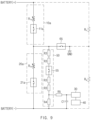
- the first resistance unit 10 and the second resistance unit 20 of the insulation resistance measurement apparatus have a parallel circuit structure using a plurality of switches and a plurality of resistors in order to have a plurality of resistance values as shown in FIG. 3 but for example, as shown in FIG. 9 , they may be designed using a variable resistor.
- FIG. 9 is a diagram schematically illustrating a circuit configuration of an insulation resistance measurement apparatus according to another embodiment of the present invention.
- the first resistance unit 10a may include a first variable resistance unit R1a that is ON/OFF controlled by the first switch 11 and can be converted into a first resistance value or a second resistance value between the positive electrode of battery C and the ground
- the second resistance unit 20a may include a second variable resistance unit R2a that is ON/OFF controlled by the third switch 21a and can be converted into a third resistance value or a fourth resistance value between the negative electrode of the battery C and the ground.
- Other configurations are as described above.
- the voltage distribution unit 50 of the insulation resistance measurement apparatus is connected in parallel with the second resistance unit 20, as shown in FIG. 2 , but for example, as shown in FIG. 10 , may be designed to be connected in parallel with the first resistance unit 10.
- FIG. 10 is a block diagram showing the configuration of an insulation resistance measurement apparatus according to another embodiment of the present invention.
- the voltage distribution unit 50a may be designed to have a parallel structure with the first resistance unit 10 between the positive electrode of the battery C and the ground. Other configurations are as described above.
- the insulation resistance measurement method according to an embodiment of the present invention described above may be implemented as a program stored in a recording medium for performing each operation, and the corresponding program is stored in the memory of the BMS of the battery rack and can be executed by the MCU.
- the method of the present invention can be written in a computer program.
- the code and code segments constituting the program can be easily inferred by computer programmers in the art.
- the created program is stored in a computer-readable recording medium (information storage medium), and can be read and executed by a computer to realize the method of the present invention.
- the recording medium may include any type of computer-readable recording medium.
- the recording medium may be provided separately from the MCU, or may be configured integrally with the MCU.
- FIG. 11 is a block diagram illustrating a hardware configuration of a battery management system (BMS) according to an embodiment of the present invention.
- BMS battery management system
- the battery management system 300 may include an MCU 310 for controlling various processing and each configuration, a memory 320 for recording an operating system program and various programs (for example, an insulation resistance measurement program of a battery), an input/output interface 330 providing an input interface and an output interface between the battery and/or the switching unit, and a communication interface 340 capable of communicating with the outside through a wired or wireless communication network.
- the computer program according to the present invention may be recorded in the memory 320 and processed by the microcontroller 310 to be implemented as a module for performing the respective functional blocks shown in FIG. 2 .
Landscapes
- Physics & Mathematics (AREA)
- General Physics & Mathematics (AREA)
- Engineering & Computer Science (AREA)
- Manufacturing & Machinery (AREA)
- Chemical & Material Sciences (AREA)
- Chemical Kinetics & Catalysis (AREA)
- Electrochemistry (AREA)
- General Chemical & Material Sciences (AREA)
- Microelectronics & Electronic Packaging (AREA)
- Measurement Of Resistance Or Impedance (AREA)
Claims (12)
- Appareil de mesure de résistance d'isolation comprenant :une première unité de résistance (10) ayant une première extrémité connectée à une électrode positive d'une batterie (C) et une deuxième extrémité connectée à une masse, dans lequel la première unité de résistance (10) peut être commandée de manière variable entre le fait d'avoir une première valeur de résistance ou une deuxième valeur de résistance supérieure à la première valeur de résistance ;une deuxième unité de résistance (20) ayant une première extrémité connectée à une électrode négative de la batterie (C) et une deuxième extrémité connectée à la masse, dans lequel la deuxième unité de résistance (20) peut être commandée de manière variable entre le fait d'avoir une troisième valeur de résistance ou une quatrième valeur de résistance supérieure à la troisième valeur de résistance ;une unité (30) de mesure de tension configurée pour mesurer une tension aux bornes de la première unité de résistance (10) et une tension aux bornes de la deuxième unité de résistance (20) ; etune unité (40) de calcul de résistance d'isolation configurée pour calculer une première valeur de résistance d'isolation entre l'électrode positive de la batterie (C) et la masse et une deuxième valeur de résistance d'isolation entre l'électrode négative de la batterie (C) et la masse sur la base de la première valeur de résistance, de la deuxième valeur de résistance, de la troisième valeur de résistance, de la quatrième valeur de résistance et la tension mesurée par l'unité (30) de mesure de tension,dans lequel la première unité de résistance (10) inclut une première unité (R1) de valeur de résistance dont la marche/arrêt est commandée par un premier commutateur (11) et une deuxième unité (R1, R2) de valeur de résistance dont la marche/arrêt est commandée par un deuxième commutateur (13),dans lequel les première et deuxième unités (R1, R2) de valeur de résistance sont connectées en parallèle entre l'électrode positive de la batterie (C) et la masse,dans lequel la deuxième unité de résistance (20) inclut une troisième unité (R1) de valeur de résistance dont la marche/arrêt est commandée par un troisième commutateur (21) et une quatrième unité (R2) de valeur de résistance dont la marche/arrêt est commandée par un quatrième commutateur (23),dans lequel les troisième et quatrième unités (R1, R2) de valeur de résistance sont connectées en parallèle entre l'électrode négative de la batterie (C) et la masse, etcaractérisé en ce quelorsque le premier commutateur (11) ou le deuxième commutateur (13) de la première unité de résistance (10) est allumé, l'unité (40) de calcul de résistance d'isolation commande le troisième commutateur (21) et le quatrième commutateur (23) de la deuxième unité de résistance (20) pour être éteints.
- Appareil de mesure de résistance d'isolation selon la revendication 1, comprenant en outre :une unité (50) de distribution de tension connectée en parallèle à la première unité de résistance (10) ou à la deuxième unité de résistance (20),dans lequel l'unité (50) de distribution de tension inclut une pluralité de résistances (R3, R4) connectées en série,dans lequel la tension mesurée par l'unité (30) de mesure de tension est une tension mesurée aux bornes de certaines de la pluralité de résistances (R4) de l'unité (50) de distribution de tension.
- Appareil de mesure de résistance d'isolation selon la revendication 2,dans lequel l'unité (40) de calcul de résistance d'isolation a un premier mode de mesure de résistance d'isolation et un deuxième mode de mesure de résistance d'isolation,dans lequel le premier mode de mesure de résistance d'isolation a un taux d'erreur plus faible que le deuxième mode de mesure de résistance d'isolation dans une première plage de mesures,dans lequel le deuxième mode de mesure de résistance d'isolation a un taux d'erreur plus faible que le premier mode de mesure de résistance d'isolation dans une deuxième plage de mesures, etdans lequel l'unité (40) de calcul de résistance d'isolation est configurée pour :calculer les première et deuxième valeurs de résistance d'isolation sur la base de la première valeur de résistance et de la troisième valeur de résistance dans le premier mode de mesure de résistance d'isolation, etcalculer les première et deuxième valeurs de résistance d'isolation sur la base de la deuxième valeur de résistance et de la quatrième valeur de résistance dans le deuxième mode de mesure de résistance d'isolation.
- Appareil de mesure de résistance d'isolation selon la revendication 3,dans lequel, pour la première valeur de résistance d'isolation, l'unité (40) de calcul de résistance d'isolation est configurée pour :
déterminer si la première valeur de résistance d'isolation est dans la première ou deuxième plage de mesures ; et calculer une première valeur de résistance d'isolation réelle dans le mode de mesure qui a le taux d'erreur le plus faible dans la première ou deuxième plage de mesures déterminée dans laquelle se situe la première valeur de résistance d'isolation, etdans lequel, pour la deuxième valeur de résistance d'isolation, l'unité (40) de calcul de résistance d'isolation est configurée pour :déterminer si la deuxième valeur de résistance d'isolation est dans la première ou deuxième plage de mesures ; etcalculer une deuxième valeur de résistance d'isolation réelle dans le mode de mesure qui a le taux d'erreur le plus faible dans la première ou deuxième plage de mesures déterminée dans laquelle est la deuxième valeur de résistance d'isolation. - Appareil de mesure de résistance d'isolation selon la revendication 1, dans lequel, lorsque le troisième commutateur (21) ou le quatrième commutateur (23) de la deuxième unité de résistance (20) est allumé, l'unité (40) de calcul de résistance d'isolation commande le premier commutateur (11) et le deuxième commutateur (13) de la première unité de résistance (10) pour être éteints.
- Appareil de mesure de résistance d'isolation selon la revendication 1, dans lequel, dans le premier mode de mesure de résistance d'isolation, l'unité (40) de calcul de résistance d'isolation est configurée pour calculer les première et deuxième valeurs de résistance d'isolation sur la base de la tension mesurée aux bornes de certaines de la pluralité de résistances (R3, R4) de l'unité (50) de distribution de tension lorsque le premier commutateur (11) est allumé et
les deuxième, troisième et quatrième commutateurs (13, 21, 23) sont éteints et la tension mesurée aux bornes de certaines de la pluralité de résistances (R3, R4) de l'unité (50) de distribution de tension lorsque le troisième commutateur (21) est allumé et les premier, deuxième et quatrième commutateurs (11, 13, 23) sont éteints. - Appareil de mesure de résistance d'isolation selon la revendication 1, dans lequel, dans le deuxième mode de mesure de résistance d'isolation, l'unité (40) de calcul de résistance d'isolation est configurée pour calculer les première et deuxième valeurs de résistance d'isolation sur la base de la tension mesurée aux bornes de certaines de la pluralité de résistances (R3, R4) de l'unité (50) de distribution de tension lorsque le deuxième commutateur (13) est allumé et les deuxième, troisième et quatrième commutateurs (11, 21, 23) sont éteints et la tension mesurée aux bornes de certaines de la pluralité de résistances (R3, R4) de l'unité (50) de distribution de tension lorsque le quatrième commutateur (23) est allumé et les premier, deuxième et troisième commutateurs (11, 12, 21) sont éteints.
- Appareil de mesure de résistance d'isolation selon la revendication 1, dans lequel les première, deuxième, troisième et quatrième valeurs de résistance varient en fonction de la batterie (C) ou en fonction d'un dispositif dans lequel est montée la batterie (C).
- Appareil de mesure de résistance d'isolation selon la revendication 2,dans lequel l'unité (50) de distribution de tension comprend en outre un commutateur (55) connecté en série à la pluralité de résistances (R3, R4), etdans lequel le commutateur (55) est configuré pour que sa marche/arrêt soit commandée.
- Appareil de mesure de résistance d'isolation selon la revendication 1,dans lequel la batterie (C) est un support de batterie, etdans lequel la masse est un châssis du support de batterie.
- Appareil de mesure de résistance d'isolation selon la revendication 3,dans lequel la première unité de résistance (10) inclut une première unité (R1a) de résistance variable qui peut changer entre la première valeur de résistance et la deuxième valeur de résistance sur la base de la commande de marche/arrêt par un premier commutateur (11a),dans lequel la première unité de résistance variable (R1a) est entre l'électrode positive de la batterie (C) et la masse,dans lequel la deuxième unité de résistance (20) inclut une deuxième unité (R2a) de résistance variable qui peut changer entre la troisième valeur de résistance et la quatrième valeur de résistance sur la base de la commande de marche/arrêt par un deuxième commutateur (21a), etdans lequel la deuxième unité de résistance variable (R2a) est entre l'électrode négative de la batterie (C) et la masse.
- Procédé de mesure de résistance d'isolation mis en oeuvre en utilisant l'un d'une pluralité de modes de mesure de résistance d'isolation donnés, dans lequel chaque mode de mesure de résistance d'isolation respectif correspond à une plage de mesures respective pour laquelle un taux d'erreur de mesure de résistance d'isolation dans une plage de mesures respective est plus faible que des taux d'erreur de mesure de résistance d'isolation pour d'autres de la pluralité de modes de mesure de résistance d'isolation dans la plage de mesures de respective, le procédé comprenant :un calcul (S20) d'une première valeur de résistance d'isolation entre une électrode positive d'une batterie (C) et une masse et une deuxième valeur de résistance d'isolation entre une électrode négative de la batterie (C) et la masse par chaque mode de mesure de résistance d'isolation ;une détermination (C30) de laquelle des plages de mesures respectives correspond à chacune des première et deuxième valeurs de résistance d'isolation ; etune détermination (C40) d'une valeur de résistance d'isolation réelle en utilisant le mode de mesure de résistance d'isolation respectif pour lequel le taux d'erreur de mesure de résistance d'isolation dans la plage de mesures déterminée est le plus faible ; etun changement entre des modes de la pluralité de modes de mesure de résistance d'isolation en changeant une valeur de résistance d'une première unité de résistance (10) ayant une première extrémité connectée à l'électrode positive de la batterie (C) et une deuxième extrémité connectée à la masse, et une valeur de résistance d'une deuxième unité de résistance (20) ayant une première extrémité connectée à l'électrode négative de la batterie (C) et une deuxième extrémité connectée à la masse,dans lequel la première unité de résistance (10) inclut une première unité (R1) de valeur de résistance dont la marche/arrêt est commandée par un premier commutateur (11) et une deuxième unité (R1, R2) de valeur de résistance dont la marche/arrêt est commandée par un deuxième commutateur (13),dans lequel les première et deuxième unités (R1, R2) de valeur de résistance sont connectées en parallèle entre l'électrode positive de la batterie (C) et la masse,dans lequel la deuxième unité de résistance (20) inclut une troisième unité (R1) de valeur de résistance dont la marche/arrêt est commandée par un troisième commutateur (21) et une quatrième unité (R2) de valeur de résistance dont la marche/arrêt est commandée par un quatrième commutateur (23),dans lequel les troisième et quatrième unités (R1, R2) de valeur de résistance sont connectées en parallèle entre l'électrode négative de la batterie (C) et la masse, etcaractérisé en ce quelorsque le premier commutateur (11) ou le deuxième commutateur (13) de la première unité de résistance (10) est allumé, le troisième commutateur (21) et le quatrième commutateur (23) de la deuxième unité de résistance (20) sont commandés pour être éteints.
Applications Claiming Priority (2)
| Application Number | Priority Date | Filing Date | Title |
|---|---|---|---|
| KR1020190000520A KR102742037B1 (ko) | 2019-01-03 | 2019-01-03 | 절연저항 측정 장치 및 방법 |
| PCT/KR2019/018052 WO2020141768A1 (fr) | 2019-01-03 | 2019-12-18 | Dispositif et procédé de mesure de résistance d'isolation |
Publications (3)
| Publication Number | Publication Date |
|---|---|
| EP3869209A1 EP3869209A1 (fr) | 2021-08-25 |
| EP3869209A4 EP3869209A4 (fr) | 2022-01-26 |
| EP3869209B1 true EP3869209B1 (fr) | 2024-08-21 |
Family
ID=71406901
Family Applications (1)
| Application Number | Title | Priority Date | Filing Date |
|---|---|---|---|
| EP19907369.3A Active EP3869209B1 (fr) | 2019-01-03 | 2019-12-18 | Dispositif et procédé de mesure de résistance d'isolation |
Country Status (8)
| Country | Link |
|---|---|
| US (1) | US11906591B2 (fr) |
| EP (1) | EP3869209B1 (fr) |
| JP (1) | JP7173642B2 (fr) |
| KR (1) | KR102742037B1 (fr) |
| CN (1) | CN113692539B (fr) |
| ES (1) | ES2987235T3 (fr) |
| HU (1) | HUE068097T2 (fr) |
| WO (1) | WO2020141768A1 (fr) |
Families Citing this family (18)
| Publication number | Priority date | Publication date | Assignee | Title |
|---|---|---|---|---|
| KR102672495B1 (ko) * | 2019-03-15 | 2024-06-07 | 에스케이온 주식회사 | 절연저항 측정 장치 |
| CN113795763B (zh) | 2019-10-31 | 2024-04-02 | 株式会社Lg新能源 | 漏电检测设备、漏电检测方法及电动车辆 |
| KR102673263B1 (ko) | 2020-09-22 | 2024-06-10 | 주식회사 엘지에너지솔루션 | 배터리 저항 산출 장치 및 방법 |
| KR102750967B1 (ko) * | 2020-09-24 | 2025-01-09 | 에스케이온 주식회사 | 배터리의 특성 산출 장치 및 방법 |
| CN112485721A (zh) * | 2020-12-21 | 2021-03-12 | 苏州绿控传动科技股份有限公司 | 一种逆变器绝缘检测电路 |
| EP4089422B1 (fr) * | 2021-05-12 | 2025-01-01 | Schneider Electric Industries SAS | Dispositif et procédé d'estimation de l'impédance d'isolation d'un réseau tt ou tn |
| CN113791277A (zh) * | 2021-09-16 | 2021-12-14 | 惠州市乐亿通科技有限公司 | 绝缘电阻检测装置及叉车 |
| KR102920220B1 (ko) * | 2021-11-12 | 2026-01-30 | 주식회사 엘지에너지솔루션 | 절연 저항 측정 장치 |
| JP7816975B2 (ja) * | 2021-12-23 | 2026-02-18 | 株式会社デンソーテン | 絶縁抵抗検出装置および故障検出方法 |
| JP7619325B2 (ja) * | 2022-05-13 | 2025-01-22 | 株式会社デンソー | 漏電検出装置 |
| WO2023228057A1 (fr) * | 2022-05-24 | 2023-11-30 | Sensata Technologies, Inc. | Surveillance d'isolation |
| WO2024084916A1 (fr) * | 2022-10-21 | 2024-04-25 | 株式会社デンソー | Dispositif de détection de fuite électrique |
| JP7772000B2 (ja) * | 2022-10-21 | 2025-11-18 | 株式会社デンソー | 漏電検出装置 |
| DE102022211892B4 (de) * | 2022-11-10 | 2025-07-17 | Schaeffler Technologies AG & Co. KG | Messanordnung zur Isolationsüberwachung bei einem Bordnetz und Bordnetz mit einer Messanordnung |
| KR102714826B1 (ko) * | 2023-06-20 | 2024-10-11 | 한화시스템 주식회사 | 배터리 시스템 절연 진단 장치 및 방법 |
| KR102714825B1 (ko) * | 2023-06-20 | 2024-10-11 | 한화시스템 주식회사 | 배터리 시스템 절연 진단 장치 및 방법 |
| CN116754839A (zh) * | 2023-06-20 | 2023-09-15 | 合众新能源汽车股份有限公司 | 电动汽车的绝缘检测方法、系统及电动汽车 |
| WO2025135925A1 (fr) * | 2023-12-22 | 2025-06-26 | 엘지이노텍 주식회사 | Dispositif de conversion de puissance |
Family Cites Families (22)
| Publication number | Priority date | Publication date | Assignee | Title |
|---|---|---|---|---|
| JP2006220520A (ja) * | 2005-02-10 | 2006-08-24 | Honda Motor Co Ltd | 非接地直流電源の絶縁抵抗測定装置及びその方法 |
| JP2007147391A (ja) * | 2005-11-25 | 2007-06-14 | Nissan Motor Co Ltd | 絶縁抵抗測定システム |
| JP5552218B2 (ja) | 2008-07-08 | 2014-07-16 | 株式会社日立製作所 | 電源装置 |
| KR100974650B1 (ko) | 2008-10-30 | 2010-08-06 | 한국표준과학연구원 | 저항 측정장치 및 측정방법 |
| JP5629671B2 (ja) | 2011-10-31 | 2014-11-26 | 日立オートモティブシステムズ株式会社 | 電源装置 |
| WO2013147494A1 (fr) | 2012-03-26 | 2013-10-03 | 주식회사 엘지화학 | Dispositif et procédé de mesure de la résistance d'isolement d'une batterie |
| CN103033729B (zh) * | 2012-11-26 | 2016-01-20 | 浙江高泰昊能科技有限公司 | 用于电池箱的绝缘检测电路及其检测方法 |
| CN103869179B (zh) * | 2012-12-14 | 2016-12-21 | 比亚迪股份有限公司 | 一种直流系统的绝缘监测方法 |
| KR101512395B1 (ko) | 2013-10-08 | 2015-04-16 | 현대오트론 주식회사 | 절연저항 측정 장치 및 방법 |
| KR101984326B1 (ko) * | 2014-01-07 | 2019-09-03 | 에스케이이노베이션 주식회사 | 배터리의 절연 저항 측정 장치 및 방법 |
| KR101771226B1 (ko) | 2014-10-02 | 2017-09-05 | 주식회사 엘지화학 | 신속하게 절연 저항을 측정할 수 있는 절연 저항 측정 장치 및 방법 |
| KR101610921B1 (ko) | 2014-11-25 | 2016-04-08 | 현대오트론 주식회사 | 선택적 스위칭을 이용한 절연 저항 측정 장치 및 방법 |
| JP6609984B2 (ja) * | 2015-05-11 | 2019-11-27 | 富士電機株式会社 | 絶縁抵抗測定方法および装置 |
| KR101936220B1 (ko) | 2015-11-16 | 2019-01-08 | 주식회사 엘지화학 | 절연 저항 측정 시스템 및 장치 |
| EP3276775B1 (fr) | 2016-07-27 | 2018-11-28 | Samsung SDI Co., Ltd. | Système de batterie pour véhicule hybride |
| CN206155187U (zh) | 2016-10-28 | 2017-05-10 | 阳光电源股份有限公司 | 一种电动汽车的电机控制器及所述电动汽车 |
| KR101991910B1 (ko) | 2016-11-16 | 2019-06-21 | 주식회사 엘지화학 | 배터리의 절연 저항 산출 장치 및 방법 |
| CN208239521U (zh) | 2017-06-09 | 2018-12-14 | 青岛鼎焌电气有限公司 | 一种光伏方阵绝缘阻抗检测电路 |
| KR102065822B1 (ko) | 2017-06-27 | 2020-02-11 | 주식회사 엘지화학 | 절연 저항 산출 시스템 및 방법 |
| CN108445296A (zh) * | 2018-01-31 | 2018-08-24 | 北京智行鸿远汽车有限公司 | 一种在线式绝缘电阻检测装置及其检测方法 |
| CN110109007B (zh) * | 2018-02-01 | 2020-10-02 | 宁德时代新能源科技股份有限公司 | 继电器内外侧绝缘阻值的获取方法及装置 |
| CN108303588B (zh) * | 2018-04-09 | 2023-09-01 | 骆驼集团武汉光谷研发中心有限公司 | 一种基于非平衡电桥的直流系统绝缘监测装置 |
-
2019
- 2019-01-03 KR KR1020190000520A patent/KR102742037B1/ko active Active
- 2019-12-18 JP JP2021528932A patent/JP7173642B2/ja active Active
- 2019-12-18 CN CN201980076615.3A patent/CN113692539B/zh active Active
- 2019-12-18 US US17/293,589 patent/US11906591B2/en active Active
- 2019-12-18 ES ES19907369T patent/ES2987235T3/es active Active
- 2019-12-18 HU HUE19907369A patent/HUE068097T2/hu unknown
- 2019-12-18 EP EP19907369.3A patent/EP3869209B1/fr active Active
- 2019-12-18 WO PCT/KR2019/018052 patent/WO2020141768A1/fr not_active Ceased
Also Published As
| Publication number | Publication date |
|---|---|
| EP3869209A1 (fr) | 2021-08-25 |
| US20220003823A1 (en) | 2022-01-06 |
| JP2022517496A (ja) | 2022-03-09 |
| EP3869209A4 (fr) | 2022-01-26 |
| KR102742037B1 (ko) | 2024-12-13 |
| US11906591B2 (en) | 2024-02-20 |
| JP7173642B2 (ja) | 2022-11-16 |
| HUE068097T2 (hu) | 2024-12-28 |
| ES2987235T3 (es) | 2024-11-14 |
| WO2020141768A1 (fr) | 2020-07-09 |
| KR20200084517A (ko) | 2020-07-13 |
| CN113692539B (zh) | 2024-07-12 |
| CN113692539A (zh) | 2021-11-23 |
Similar Documents
| Publication | Publication Date | Title |
|---|---|---|
| EP3869209B1 (fr) | Dispositif et procédé de mesure de résistance d'isolation | |
| US10620273B2 (en) | Method and apparatus for estimating a state of health of a battery pack and computer-readable medium | |
| CN111060791A (zh) | 绝缘故障检测方法、装置、电动汽车、终端设备及介质 | |
| KR101746141B1 (ko) | 절연저항측정 장치 및 방법 | |
| US10048319B2 (en) | Estimating of the state of charge of a battery | |
| JP5997371B2 (ja) | 電池監視装置及びそれを用いた電池システム | |
| KR101263385B1 (ko) | 밸런싱 기능 검증이 가능한 bms 시뮬레이터 및 이를 이용한 검증 방법 | |
| US10573936B2 (en) | Remaining battery life prediction device and battery pack | |
| EP3730957A1 (fr) | Dispositif et procédé de calcul de capacité de charge pour système de stockage d'énergie | |
| EP3901640B1 (fr) | Appareil de mesure de la résistance d'isolation | |
| KR101759532B1 (ko) | 배터리의 내부 임피던스를 추정하는 방법 | |
| US12270862B2 (en) | Battery monitor system | |
| CN111771129B (zh) | 一种用于测量电流的装置、方法及设备 | |
| US20200313248A1 (en) | Apparatus and Method for Diagnosing Insulation Condition Between Battery Pack and Ground, and Battery Pack Including the Apparatus | |
| CN111983492A (zh) | 电池健康分析方法、装置和设备 | |
| JP2025502091A (ja) | 電池の充電深度算出装置およびその動作方法 | |
| JP2007240299A (ja) | フライングキャパシタ方式電圧測定装置 | |
| JPWO2020003850A1 (ja) | 集積回路、電池監視装置、及び、電池監視システム | |
| KR20190071439A (ko) | 전류 측정 장치 및 방법 | |
| KR20210011235A (ko) | 배터리 셀 진단 장치 및 방법 | |
| EP4246160B1 (fr) | Dispositif et procédé de gestion de batterie | |
| CN118519036A (zh) | 极点确定方法、装置、车辆、存储介质及程序产品 | |
| CN104749530A (zh) | 一种动力电池放电自耗能性能衰变估算方法及装置 | |
| JP3191452B2 (ja) | 電子部品測定装置 | |
| EP4261553A1 (fr) | Procédé de gestion de batterie et système de batterie utilisant celui-ci |
Legal Events
| Date | Code | Title | Description |
|---|---|---|---|
| STAA | Information on the status of an ep patent application or granted ep patent |
Free format text: STATUS: THE INTERNATIONAL PUBLICATION HAS BEEN MADE |
|
| PUAI | Public reference made under article 153(3) epc to a published international application that has entered the european phase |
Free format text: ORIGINAL CODE: 0009012 |
|
| STAA | Information on the status of an ep patent application or granted ep patent |
Free format text: STATUS: REQUEST FOR EXAMINATION WAS MADE |
|
| 17P | Request for examination filed |
Effective date: 20210518 |
|
| AK | Designated contracting states |
Kind code of ref document: A1 Designated state(s): AL AT BE BG CH CY CZ DE DK EE ES FI FR GB GR HR HU IE IS IT LI LT LU LV MC MK MT NL NO PL PT RO RS SE SI SK SM TR |
|
| A4 | Supplementary search report drawn up and despatched |
Effective date: 20220105 |
|
| RIC1 | Information provided on ipc code assigned before grant |
Ipc: G01R 31/36 20200101ALI20211222BHEP Ipc: G01R 31/52 20200101ALI20211222BHEP Ipc: G01R 27/18 20060101ALI20211222BHEP Ipc: H01M 10/48 20060101ALI20211222BHEP Ipc: G01R 31/385 20190101ALI20211222BHEP Ipc: G01R 27/02 20060101AFI20211222BHEP |
|
| RIC1 | Information provided on ipc code assigned before grant |
Ipc: G01R 31/36 20200101ALI20220120BHEP Ipc: G01R 31/52 20200101ALI20220120BHEP Ipc: G01R 27/18 20060101ALI20220120BHEP Ipc: H01M 10/48 20060101ALI20220120BHEP Ipc: G01R 31/385 20190101ALI20220120BHEP Ipc: G01R 27/02 20060101AFI20220120BHEP |
|
| RAP3 | Party data changed (applicant data changed or rights of an application transferred) |
Owner name: LG ENERGY SOLUTION, LTD. |
|
| DAV | Request for validation of the european patent (deleted) | ||
| DAX | Request for extension of the european patent (deleted) | ||
| GRAP | Despatch of communication of intention to grant a patent |
Free format text: ORIGINAL CODE: EPIDOSNIGR1 |
|
| STAA | Information on the status of an ep patent application or granted ep patent |
Free format text: STATUS: GRANT OF PATENT IS INTENDED |
|
| INTG | Intention to grant announced |
Effective date: 20240314 |
|
| GRAS | Grant fee paid |
Free format text: ORIGINAL CODE: EPIDOSNIGR3 |
|
| GRAA | (expected) grant |
Free format text: ORIGINAL CODE: 0009210 |
|
| STAA | Information on the status of an ep patent application or granted ep patent |
Free format text: STATUS: THE PATENT HAS BEEN GRANTED |
|
| P01 | Opt-out of the competence of the unified patent court (upc) registered |
Free format text: CASE NUMBER: APP_40233/2024 Effective date: 20240705 |
|
| AK | Designated contracting states |
Kind code of ref document: B1 Designated state(s): AL AT BE BG CH CY CZ DE DK EE ES FI FR GB GR HR HU IE IS IT LI LT LU LV MC MK MT NL NO PL PT RO RS SE SI SK SM TR |
|
| REG | Reference to a national code |
Ref country code: GB Ref legal event code: FG4D |
|
| REG | Reference to a national code |
Ref country code: CH Ref legal event code: EP |
|
| REG | Reference to a national code |
Ref country code: DE Ref legal event code: R096 Ref document number: 602019057662 Country of ref document: DE |
|
| REG | Reference to a national code |
Ref country code: IE Ref legal event code: FG4D |
|
| REG | Reference to a national code |
Ref country code: ES Ref legal event code: FG2A Ref document number: 2987235 Country of ref document: ES Kind code of ref document: T3 Effective date: 20241114 |
|
| REG | Reference to a national code |
Ref country code: LT Ref legal event code: MG9D |
|
| REG | Reference to a national code |
Ref country code: HU Ref legal event code: AG4A Ref document number: E068097 Country of ref document: HU |
|
| REG | Reference to a national code |
Ref country code: NL Ref legal event code: MP Effective date: 20240821 |
|
| PG25 | Lapsed in a contracting state [announced via postgrant information from national office to epo] |
Ref country code: NO Free format text: LAPSE BECAUSE OF FAILURE TO SUBMIT A TRANSLATION OF THE DESCRIPTION OR TO PAY THE FEE WITHIN THE PRESCRIBED TIME-LIMIT Effective date: 20241121 |
|
| REG | Reference to a national code |
Ref country code: AT Ref legal event code: MK05 Ref document number: 1715993 Country of ref document: AT Kind code of ref document: T Effective date: 20240821 |
|
| PG25 | Lapsed in a contracting state [announced via postgrant information from national office to epo] |
Ref country code: NL Free format text: LAPSE BECAUSE OF FAILURE TO SUBMIT A TRANSLATION OF THE DESCRIPTION OR TO PAY THE FEE WITHIN THE PRESCRIBED TIME-LIMIT Effective date: 20240821 Ref country code: GR Free format text: LAPSE BECAUSE OF FAILURE TO SUBMIT A TRANSLATION OF THE DESCRIPTION OR TO PAY THE FEE WITHIN THE PRESCRIBED TIME-LIMIT Effective date: 20241122 Ref country code: FI Free format text: LAPSE BECAUSE OF FAILURE TO SUBMIT A TRANSLATION OF THE DESCRIPTION OR TO PAY THE FEE WITHIN THE PRESCRIBED TIME-LIMIT Effective date: 20240821 Ref country code: PL Free format text: LAPSE BECAUSE OF FAILURE TO SUBMIT A TRANSLATION OF THE DESCRIPTION OR TO PAY THE FEE WITHIN THE PRESCRIBED TIME-LIMIT Effective date: 20240821 Ref country code: PT Free format text: LAPSE BECAUSE OF FAILURE TO SUBMIT A TRANSLATION OF THE DESCRIPTION OR TO PAY THE FEE WITHIN THE PRESCRIBED TIME-LIMIT Effective date: 20241223 |
|
| PG25 | Lapsed in a contracting state [announced via postgrant information from national office to epo] |
Ref country code: BG Free format text: LAPSE BECAUSE OF FAILURE TO SUBMIT A TRANSLATION OF THE DESCRIPTION OR TO PAY THE FEE WITHIN THE PRESCRIBED TIME-LIMIT Effective date: 20240821 |
|
| PG25 | Lapsed in a contracting state [announced via postgrant information from national office to epo] |
Ref country code: LV Free format text: LAPSE BECAUSE OF FAILURE TO SUBMIT A TRANSLATION OF THE DESCRIPTION OR TO PAY THE FEE WITHIN THE PRESCRIBED TIME-LIMIT Effective date: 20240821 |
|
| PG25 | Lapsed in a contracting state [announced via postgrant information from national office to epo] |
Ref country code: AT Free format text: LAPSE BECAUSE OF FAILURE TO SUBMIT A TRANSLATION OF THE DESCRIPTION OR TO PAY THE FEE WITHIN THE PRESCRIBED TIME-LIMIT Effective date: 20240821 Ref country code: IS Free format text: LAPSE BECAUSE OF FAILURE TO SUBMIT A TRANSLATION OF THE DESCRIPTION OR TO PAY THE FEE WITHIN THE PRESCRIBED TIME-LIMIT Effective date: 20241221 |
|
| PG25 | Lapsed in a contracting state [announced via postgrant information from national office to epo] |
Ref country code: HR Free format text: LAPSE BECAUSE OF FAILURE TO SUBMIT A TRANSLATION OF THE DESCRIPTION OR TO PAY THE FEE WITHIN THE PRESCRIBED TIME-LIMIT Effective date: 20240821 |
|
| PG25 | Lapsed in a contracting state [announced via postgrant information from national office to epo] |
Ref country code: RS Free format text: LAPSE BECAUSE OF FAILURE TO SUBMIT A TRANSLATION OF THE DESCRIPTION OR TO PAY THE FEE WITHIN THE PRESCRIBED TIME-LIMIT Effective date: 20241121 |
|
| PG25 | Lapsed in a contracting state [announced via postgrant information from national office to epo] |
Ref country code: RS Free format text: LAPSE BECAUSE OF FAILURE TO SUBMIT A TRANSLATION OF THE DESCRIPTION OR TO PAY THE FEE WITHIN THE PRESCRIBED TIME-LIMIT Effective date: 20241121 Ref country code: PT Free format text: LAPSE BECAUSE OF FAILURE TO SUBMIT A TRANSLATION OF THE DESCRIPTION OR TO PAY THE FEE WITHIN THE PRESCRIBED TIME-LIMIT Effective date: 20241223 Ref country code: PL Free format text: LAPSE BECAUSE OF FAILURE TO SUBMIT A TRANSLATION OF THE DESCRIPTION OR TO PAY THE FEE WITHIN THE PRESCRIBED TIME-LIMIT Effective date: 20240821 Ref country code: NO Free format text: LAPSE BECAUSE OF FAILURE TO SUBMIT A TRANSLATION OF THE DESCRIPTION OR TO PAY THE FEE WITHIN THE PRESCRIBED TIME-LIMIT Effective date: 20241121 Ref country code: NL Free format text: LAPSE BECAUSE OF FAILURE TO SUBMIT A TRANSLATION OF THE DESCRIPTION OR TO PAY THE FEE WITHIN THE PRESCRIBED TIME-LIMIT Effective date: 20240821 Ref country code: LV Free format text: LAPSE BECAUSE OF FAILURE TO SUBMIT A TRANSLATION OF THE DESCRIPTION OR TO PAY THE FEE WITHIN THE PRESCRIBED TIME-LIMIT Effective date: 20240821 Ref country code: IS Free format text: LAPSE BECAUSE OF FAILURE TO SUBMIT A TRANSLATION OF THE DESCRIPTION OR TO PAY THE FEE WITHIN THE PRESCRIBED TIME-LIMIT Effective date: 20241221 Ref country code: HR Free format text: LAPSE BECAUSE OF FAILURE TO SUBMIT A TRANSLATION OF THE DESCRIPTION OR TO PAY THE FEE WITHIN THE PRESCRIBED TIME-LIMIT Effective date: 20240821 Ref country code: GR Free format text: LAPSE BECAUSE OF FAILURE TO SUBMIT A TRANSLATION OF THE DESCRIPTION OR TO PAY THE FEE WITHIN THE PRESCRIBED TIME-LIMIT Effective date: 20241122 Ref country code: FI Free format text: LAPSE BECAUSE OF FAILURE TO SUBMIT A TRANSLATION OF THE DESCRIPTION OR TO PAY THE FEE WITHIN THE PRESCRIBED TIME-LIMIT Effective date: 20240821 Ref country code: BG Free format text: LAPSE BECAUSE OF FAILURE TO SUBMIT A TRANSLATION OF THE DESCRIPTION OR TO PAY THE FEE WITHIN THE PRESCRIBED TIME-LIMIT Effective date: 20240821 Ref country code: AT Free format text: LAPSE BECAUSE OF FAILURE TO SUBMIT A TRANSLATION OF THE DESCRIPTION OR TO PAY THE FEE WITHIN THE PRESCRIBED TIME-LIMIT Effective date: 20240821 |
|
| PG25 | Lapsed in a contracting state [announced via postgrant information from national office to epo] |
Ref country code: RO Free format text: LAPSE BECAUSE OF FAILURE TO SUBMIT A TRANSLATION OF THE DESCRIPTION OR TO PAY THE FEE WITHIN THE PRESCRIBED TIME-LIMIT Effective date: 20240821 Ref country code: SM Free format text: LAPSE BECAUSE OF FAILURE TO SUBMIT A TRANSLATION OF THE DESCRIPTION OR TO PAY THE FEE WITHIN THE PRESCRIBED TIME-LIMIT Effective date: 20240821 Ref country code: DK Free format text: LAPSE BECAUSE OF FAILURE TO SUBMIT A TRANSLATION OF THE DESCRIPTION OR TO PAY THE FEE WITHIN THE PRESCRIBED TIME-LIMIT Effective date: 20240821 |
|
| PG25 | Lapsed in a contracting state [announced via postgrant information from national office to epo] |
Ref country code: EE Free format text: LAPSE BECAUSE OF FAILURE TO SUBMIT A TRANSLATION OF THE DESCRIPTION OR TO PAY THE FEE WITHIN THE PRESCRIBED TIME-LIMIT Effective date: 20240821 |
|
| PG25 | Lapsed in a contracting state [announced via postgrant information from national office to epo] |
Ref country code: CZ Free format text: LAPSE BECAUSE OF FAILURE TO SUBMIT A TRANSLATION OF THE DESCRIPTION OR TO PAY THE FEE WITHIN THE PRESCRIBED TIME-LIMIT Effective date: 20240821 |
|
| PG25 | Lapsed in a contracting state [announced via postgrant information from national office to epo] |
Ref country code: IT Free format text: LAPSE BECAUSE OF FAILURE TO SUBMIT A TRANSLATION OF THE DESCRIPTION OR TO PAY THE FEE WITHIN THE PRESCRIBED TIME-LIMIT Effective date: 20240821 Ref country code: SK Free format text: LAPSE BECAUSE OF FAILURE TO SUBMIT A TRANSLATION OF THE DESCRIPTION OR TO PAY THE FEE WITHIN THE PRESCRIBED TIME-LIMIT Effective date: 20240821 |
|
| REG | Reference to a national code |
Ref country code: DE Ref legal event code: R097 Ref document number: 602019057662 Country of ref document: DE |
|
| PLBE | No opposition filed within time limit |
Free format text: ORIGINAL CODE: 0009261 |
|
| STAA | Information on the status of an ep patent application or granted ep patent |
Free format text: STATUS: NO OPPOSITION FILED WITHIN TIME LIMIT |
|
| PG25 | Lapsed in a contracting state [announced via postgrant information from national office to epo] |
Ref country code: MC Free format text: LAPSE BECAUSE OF FAILURE TO SUBMIT A TRANSLATION OF THE DESCRIPTION OR TO PAY THE FEE WITHIN THE PRESCRIBED TIME-LIMIT Effective date: 20240821 |
|
| 26N | No opposition filed |
Effective date: 20250522 |
|
| REG | Reference to a national code |
Ref country code: CH Ref legal event code: PL |
|
| PG25 | Lapsed in a contracting state [announced via postgrant information from national office to epo] |
Ref country code: LU Free format text: LAPSE BECAUSE OF NON-PAYMENT OF DUE FEES Effective date: 20241218 |
|
| PG25 | Lapsed in a contracting state [announced via postgrant information from national office to epo] |
Ref country code: SE Free format text: LAPSE BECAUSE OF FAILURE TO SUBMIT A TRANSLATION OF THE DESCRIPTION OR TO PAY THE FEE WITHIN THE PRESCRIBED TIME-LIMIT Effective date: 20240821 |
|
| PG25 | Lapsed in a contracting state [announced via postgrant information from national office to epo] |
Ref country code: CH Free format text: LAPSE BECAUSE OF NON-PAYMENT OF DUE FEES Effective date: 20241231 |
|
| PG25 | Lapsed in a contracting state [announced via postgrant information from national office to epo] |
Ref country code: IE Free format text: LAPSE BECAUSE OF NON-PAYMENT OF DUE FEES Effective date: 20241218 |
|
| PGFP | Annual fee paid to national office [announced via postgrant information from national office to epo] |
Ref country code: DE Payment date: 20251120 Year of fee payment: 7 |
|
| PGFP | Annual fee paid to national office [announced via postgrant information from national office to epo] |
Ref country code: GB Payment date: 20251120 Year of fee payment: 7 |
|
| PGFP | Annual fee paid to national office [announced via postgrant information from national office to epo] |
Ref country code: HU Payment date: 20251216 Year of fee payment: 7 Ref country code: FR Payment date: 20251125 Year of fee payment: 7 |
|
| PGFP | Annual fee paid to national office [announced via postgrant information from national office to epo] |
Ref country code: BE Payment date: 20251120 Year of fee payment: 7 |
|
| PGFP | Annual fee paid to national office [announced via postgrant information from national office to epo] |
Ref country code: ES Payment date: 20260122 Year of fee payment: 7 |