EP3869723A1 - Procédé et appareil de transmission d'informations d'état de canal - Google Patents
Procédé et appareil de transmission d'informations d'état de canal Download PDFInfo
- Publication number
- EP3869723A1 EP3869723A1 EP19883603.3A EP19883603A EP3869723A1 EP 3869723 A1 EP3869723 A1 EP 3869723A1 EP 19883603 A EP19883603 A EP 19883603A EP 3869723 A1 EP3869723 A1 EP 3869723A1
- Authority
- EP
- European Patent Office
- Prior art keywords
- csi
- resource
- control channel
- physical uplink
- uplink control
- Prior art date
- Legal status (The legal status is an assumption and is not a legal conclusion. Google has not performed a legal analysis and makes no representation as to the accuracy of the status listed.)
- Withdrawn
Links
- 238000000034 method Methods 0.000 title claims abstract description 55
- 230000011664 signaling Effects 0.000 claims abstract description 53
- 230000005540 biological transmission Effects 0.000 claims abstract description 20
- 238000012545 processing Methods 0.000 claims description 15
- 238000004891 communication Methods 0.000 description 42
- 238000005259 measurement Methods 0.000 description 21
- 230000006870 function Effects 0.000 description 20
- 238000013461 design Methods 0.000 description 17
- 239000011159 matrix material Substances 0.000 description 13
- 238000010586 diagram Methods 0.000 description 7
- 230000000737 periodic effect Effects 0.000 description 7
- 238000004590 computer program Methods 0.000 description 6
- 230000007774 longterm Effects 0.000 description 4
- 238000000354 decomposition reaction Methods 0.000 description 3
- 238000013507 mapping Methods 0.000 description 3
- 230000008569 process Effects 0.000 description 3
- 230000006399 behavior Effects 0.000 description 2
- 238000004422 calculation algorithm Methods 0.000 description 2
- 238000004364 calculation method Methods 0.000 description 2
- 230000001413 cellular effect Effects 0.000 description 2
- 230000001427 coherent effect Effects 0.000 description 2
- 238000001514 detection method Methods 0.000 description 2
- 238000012544 monitoring process Methods 0.000 description 2
- 239000007787 solid Substances 0.000 description 2
- 101000741965 Homo sapiens Inactive tyrosine-protein kinase PRAG1 Proteins 0.000 description 1
- 102100038659 Inactive tyrosine-protein kinase PRAG1 Human genes 0.000 description 1
- 238000013500 data storage Methods 0.000 description 1
- 230000004069 differentiation Effects 0.000 description 1
- 238000005516 engineering process Methods 0.000 description 1
- 230000006872 improvement Effects 0.000 description 1
- 230000003993 interaction Effects 0.000 description 1
- 238000010295 mobile communication Methods 0.000 description 1
- 230000004048 modification Effects 0.000 description 1
- 238000012986 modification Methods 0.000 description 1
- 230000003287 optical effect Effects 0.000 description 1
- 239000013307 optical fiber Substances 0.000 description 1
- 230000008520 organization Effects 0.000 description 1
- 239000004065 semiconductor Substances 0.000 description 1
- 230000001960 triggered effect Effects 0.000 description 1
Images


Classifications
-
- H—ELECTRICITY
- H04—ELECTRIC COMMUNICATION TECHNIQUE
- H04L—TRANSMISSION OF DIGITAL INFORMATION, e.g. TELEGRAPHIC COMMUNICATION
- H04L5/00—Arrangements affording multiple use of the transmission path
- H04L5/003—Arrangements for allocating sub-channels of the transmission path
- H04L5/0053—Allocation of signalling, i.e. of overhead other than pilot signals
- H04L5/0057—Physical resource allocation for CQI
-
- H—ELECTRICITY
- H04—ELECTRIC COMMUNICATION TECHNIQUE
- H04W—WIRELESS COMMUNICATION NETWORKS
- H04W72/00—Local resource management
- H04W72/50—Allocation or scheduling criteria for wireless resources
- H04W72/54—Allocation or scheduling criteria for wireless resources based on quality criteria
-
- H—ELECTRICITY
- H04—ELECTRIC COMMUNICATION TECHNIQUE
- H04L—TRANSMISSION OF DIGITAL INFORMATION, e.g. TELEGRAPHIC COMMUNICATION
- H04L5/00—Arrangements affording multiple use of the transmission path
- H04L5/003—Arrangements for allocating sub-channels of the transmission path
- H04L5/0053—Allocation of signalling, i.e. of overhead other than pilot signals
-
- H—ELECTRICITY
- H04—ELECTRIC COMMUNICATION TECHNIQUE
- H04B—TRANSMISSION
- H04B7/00—Radio transmission systems, i.e. using radiation field
- H04B7/02—Diversity systems; Multi-antenna system, i.e. transmission or reception using multiple antennas
- H04B7/04—Diversity systems; Multi-antenna system, i.e. transmission or reception using multiple antennas using two or more spaced independent antennas
- H04B7/0413—MIMO systems
- H04B7/0456—Selection of precoding matrices or codebooks, e.g. using matrices antenna weighting
-
- H—ELECTRICITY
- H04—ELECTRIC COMMUNICATION TECHNIQUE
- H04B—TRANSMISSION
- H04B7/00—Radio transmission systems, i.e. using radiation field
- H04B7/02—Diversity systems; Multi-antenna system, i.e. transmission or reception using multiple antennas
- H04B7/04—Diversity systems; Multi-antenna system, i.e. transmission or reception using multiple antennas using two or more spaced independent antennas
- H04B7/06—Diversity systems; Multi-antenna system, i.e. transmission or reception using multiple antennas using two or more spaced independent antennas at the transmitting station
- H04B7/0613—Diversity systems; Multi-antenna system, i.e. transmission or reception using multiple antennas using two or more spaced independent antennas at the transmitting station using simultaneous transmission
- H04B7/0615—Diversity systems; Multi-antenna system, i.e. transmission or reception using multiple antennas using two or more spaced independent antennas at the transmitting station using simultaneous transmission of weighted versions of same signal
- H04B7/0619—Diversity systems; Multi-antenna system, i.e. transmission or reception using multiple antennas using two or more spaced independent antennas at the transmitting station using simultaneous transmission of weighted versions of same signal using feedback from receiving side
- H04B7/0621—Feedback content
- H04B7/0626—Channel coefficients, e.g. channel state information [CSI]
-
- H—ELECTRICITY
- H04—ELECTRIC COMMUNICATION TECHNIQUE
- H04B—TRANSMISSION
- H04B7/00—Radio transmission systems, i.e. using radiation field
- H04B7/02—Diversity systems; Multi-antenna system, i.e. transmission or reception using multiple antennas
- H04B7/04—Diversity systems; Multi-antenna system, i.e. transmission or reception using multiple antennas using two or more spaced independent antennas
- H04B7/06—Diversity systems; Multi-antenna system, i.e. transmission or reception using multiple antennas using two or more spaced independent antennas at the transmitting station
- H04B7/0613—Diversity systems; Multi-antenna system, i.e. transmission or reception using multiple antennas using two or more spaced independent antennas at the transmitting station using simultaneous transmission
- H04B7/0615—Diversity systems; Multi-antenna system, i.e. transmission or reception using multiple antennas using two or more spaced independent antennas at the transmitting station using simultaneous transmission of weighted versions of same signal
- H04B7/0619—Diversity systems; Multi-antenna system, i.e. transmission or reception using multiple antennas using two or more spaced independent antennas at the transmitting station using simultaneous transmission of weighted versions of same signal using feedback from receiving side
- H04B7/0636—Feedback format
- H04B7/0645—Variable feedback
-
- H—ELECTRICITY
- H04—ELECTRIC COMMUNICATION TECHNIQUE
- H04L—TRANSMISSION OF DIGITAL INFORMATION, e.g. TELEGRAPHIC COMMUNICATION
- H04L5/00—Arrangements affording multiple use of the transmission path
- H04L5/003—Arrangements for allocating sub-channels of the transmission path
- H04L5/0048—Allocation of pilot signals, i.e. of signals known to the receiver
-
- H—ELECTRICITY
- H04—ELECTRIC COMMUNICATION TECHNIQUE
- H04L—TRANSMISSION OF DIGITAL INFORMATION, e.g. TELEGRAPHIC COMMUNICATION
- H04L5/00—Arrangements affording multiple use of the transmission path
- H04L5/003—Arrangements for allocating sub-channels of the transmission path
- H04L5/0078—Timing of allocation
- H04L5/0082—Timing of allocation at predetermined intervals
-
- H—ELECTRICITY
- H04—ELECTRIC COMMUNICATION TECHNIQUE
- H04L—TRANSMISSION OF DIGITAL INFORMATION, e.g. TELEGRAPHIC COMMUNICATION
- H04L5/00—Arrangements affording multiple use of the transmission path
- H04L5/003—Arrangements for allocating sub-channels of the transmission path
- H04L5/0078—Timing of allocation
- H04L5/0085—Timing of allocation when channel conditions change
-
- H—ELECTRICITY
- H04—ELECTRIC COMMUNICATION TECHNIQUE
- H04L—TRANSMISSION OF DIGITAL INFORMATION, e.g. TELEGRAPHIC COMMUNICATION
- H04L5/00—Arrangements affording multiple use of the transmission path
- H04L5/0091—Signalling for the administration of the divided path, e.g. signalling of configuration information
- H04L5/0094—Indication of how sub-channels of the path are allocated
-
- H—ELECTRICITY
- H04—ELECTRIC COMMUNICATION TECHNIQUE
- H04W—WIRELESS COMMUNICATION NETWORKS
- H04W72/00—Local resource management
- H04W72/02—Selection of wireless resources by user or terminal
-
- H—ELECTRICITY
- H04—ELECTRIC COMMUNICATION TECHNIQUE
- H04W—WIRELESS COMMUNICATION NETWORKS
- H04W72/00—Local resource management
- H04W72/04—Wireless resource allocation
- H04W72/044—Wireless resource allocation based on the type of the allocated resource
- H04W72/0446—Resources in time domain, e.g. slots or frames
-
- H—ELECTRICITY
- H04—ELECTRIC COMMUNICATION TECHNIQUE
- H04W—WIRELESS COMMUNICATION NETWORKS
- H04W72/00—Local resource management
- H04W72/20—Control channels or signalling for resource management
- H04W72/23—Control channels or signalling for resource management in the downlink direction of a wireless link, i.e. towards a terminal
-
- H—ELECTRICITY
- H04—ELECTRIC COMMUNICATION TECHNIQUE
- H04L—TRANSMISSION OF DIGITAL INFORMATION, e.g. TELEGRAPHIC COMMUNICATION
- H04L1/00—Arrangements for detecting or preventing errors in the information received
- H04L1/12—Arrangements for detecting or preventing errors in the information received by using return channel
- H04L1/16—Arrangements for detecting or preventing errors in the information received by using return channel in which the return channel carries supervisory signals, e.g. repetition request signals
- H04L1/18—Automatic repetition systems, e.g. Van Duuren systems
- H04L1/1829—Arrangements specially adapted for the receiver end
- H04L1/1854—Scheduling and prioritising arrangements
-
- H—ELECTRICITY
- H04—ELECTRIC COMMUNICATION TECHNIQUE
- H04L—TRANSMISSION OF DIGITAL INFORMATION, e.g. TELEGRAPHIC COMMUNICATION
- H04L27/00—Modulated-carrier systems
- H04L27/26—Systems using multi-frequency codes
- H04L27/2601—Multicarrier modulation systems
- H04L27/2602—Signal structure
-
- H—ELECTRICITY
- H04—ELECTRIC COMMUNICATION TECHNIQUE
- H04L—TRANSMISSION OF DIGITAL INFORMATION, e.g. TELEGRAPHIC COMMUNICATION
- H04L5/00—Arrangements affording multiple use of the transmission path
- H04L5/0001—Arrangements for dividing the transmission path
- H04L5/0003—Two-dimensional division
- H04L5/0005—Time-frequency
- H04L5/0007—Time-frequency the frequencies being orthogonal, e.g. OFDM(A) or DMT
-
- H—ELECTRICITY
- H04—ELECTRIC COMMUNICATION TECHNIQUE
- H04L—TRANSMISSION OF DIGITAL INFORMATION, e.g. TELEGRAPHIC COMMUNICATION
- H04L5/00—Arrangements affording multiple use of the transmission path
- H04L5/003—Arrangements for allocating sub-channels of the transmission path
- H04L5/0058—Allocation criteria
- H04L5/006—Quality of the received signal, e.g. BER, SNR, water filling
Definitions
- Embodiments of this application relate to communications technologies, and in particular, to a channel state information transmission method and an apparatus.
- the 3GPP standard organization is currently formulating protocol standards for a 5th generation cellular mobile communications system (5th Generation, 5G for short below, also referred to as new radio (New Radio, NR)).
- a channel state information reference signal (Channel state information reference signal, CSI-RS) is introduced in LTE Release 10 (release 10, R10). Similar to channel state information (Channel state information, CSI) measurement in 4G LTE, CSI measurement in NR is also based on a received CSI-RS, and channel estimation is performed on the received CSI-RS, to obtain a channel state measurement result and an interference measurement result.
- the CSI measurement includes periodic measurement and aperiodic measurement.
- a network device triggers aperiodic CSI reporting (when a value of a CSI request field is not 0) by using the CSI request field in downlink control information (DCI format 0_1) used for uplink scheduling.
- the CSI request field indicates a specific trigger state that triggers the aperiodic CSI reporting.
- the network device sends an aperiodic CSI-RS resource in an aperiodic CSI-RS resource set bound to the trigger state.
- the UE After user equipment (UE) receives and parses the downlink control information (DCI format 0_1) used for uplink scheduling, and learns that the aperiodic CSI reporting is triggered, the UE measures the bound aperiodic CSI-RS resource based on the trigger state indicated by the CSI request field, and reports CSI by using a PUSCH scheduled by the downlink control information (DCI format 0_1) used for uplink scheduling.
- DCI format 0_1 downlink control information
- the network device can trigger the aperiodic CSI reporting only by using the foregoing downlink control information (DCI format 0_1) used for uplink scheduling, but this aperiodic CSI reporting manner is not flexible enough.
- DCI format 0_1 downlink control information
- an embodiment of this application provides a channel state information transmission method, including: receiving first higher layer signaling sent by a network device, where the first higher layer signaling is used to indicate a first physical uplink control channel, and the first physical uplink control channel is a channel used to periodically report channel state information CSI; receiving downlink control information sent by the network device, where the downlink control information is used to schedule a physical downlink shared channel; and sending the CSI by using the first physical uplink control channel and a second physical uplink control channel, or sending the CSI by using a second physical uplink control channel, where the second physical uplink control channel is indicated by the downlink control information or second higher layer signaling, a time at which the CSI is sent by using the second physical uplink control channel is earlier than a time at which the CSI is sent by using a first physical uplink control channel in a next periodicity, and the next periodicity is a next periodicity of a periodicity in which the current first physical uplink control channel is located.
- the CSI is sent by using the first PUCCH and the second PUCCH, or the CSI is sent by using the second PUCCH. Because the second PUCCH is indicated by the DCI or the second higher layer signaling, and a time domain position of the second PUCCH is earlier than that of the first PUCCH in the next periodicity, the CSI can be reported flexibly and quickly.
- the time domain position at which the second physical uplink control channel is located is earlier than a time domain position at which any third physical uplink control channel is located, each third physical uplink control channel is a channel used to periodically report the CSI, and the third physical uplink control channel and the first physical uplink control channel belong to different periodicities.
- the CSI is sent by using the third PUCCH and the second PUCCH, or the CSI is sent by using the second PUCCH. Because the time domain position of the second PUCCH is earlier than that of the third PUCCH, the CSI can be reported flexibly and quickly.
- the method further includes: determining the CSI based on a reference signal RS resource, where the RS resource includes at least one of a CSI-RS resource, a physical downlink shared channel data demodulation reference signal PDSCH DMRS resource, and a physical downlink control channel demodulation reference signal PDCCH DMRS resource; and sending indication information to the network device, where the indication information is used to indicate an index of the RS resource used to determine the CSI.
- the CSI is determined based on at least one of the CSI-RS resource, the physical downlink shared channel data demodulation reference signal PDSCH DMRS resource, and the physical downlink control channel demodulation reference signal PDCCH DMRS resource, and the index of the RS resource used to determine the CSI is indicated to the network device by using the indication information.
- the network device can determine, based on the index, a reference signal corresponding to the CSI, and determine channel quality of a corresponding bandwidth based on a frequency domain resource occupied by the reference signal.
- the RS resource used to determine the CSI is the CSI-RS resource
- the last time domain symbol in which the CSI-RS resource is located is before the second physical uplink control channel by a first preset quantity of time domain symbols, and the first preset quantity is greater than 0.
- the RS resource used to determine the CSI is the CSI-RS resource; and a time domain symbol in which the CSI-RS resource is located is not earlier than the first time domain symbol of the downlink control information; or the CSI-RS resource includes a first CSI-RS resource and a second CSI-RS resource, the first CSI-RS resource is not earlier than a next time domain symbol of the last time domain symbol of a closest first physical uplink control channel, the closest first physical uplink control channel is before the second physical uplink control channel and is closest to the time domain position of the second physical uplink control channel, each second CSI-RS resource is not earlier than a next time domain symbol of the last time domain symbol of a closest third physical uplink control channel, and the closest third physical uplink control channel is before the second physical uplink control channel, closest to the time domain position of the second physical uplink control channel, and bound to the second CSI-RS resource.
- the RS resource used to determine the CSI is the CSI-RS resource
- the first time domain symbol in which the CSI-RS resource is located is not earlier than the second physical uplink control channel by a second preset quantity of time domain symbols
- the second preset quantity is a sum of the first preset quantity and a third preset quantity
- the third preset quantity is greater than 0.
- the foregoing design avoids a case in which due to excessively long duration of a resource selection window used for CSI-RS resource selection, a relatively large quantity of CSI-RS resources fall within the window and cannot be processed by the terminal device, and sending of the CSI on the second PUCCH is affected.
- the RS resource used to determine the CSI is the CSI-RS resource
- the CSI-RS resource is M CSI-RS resources
- the method further includes: selecting, from the M CSI-RS resources, min ⁇ N,M ⁇ CSI-RS resources whose time domain positions are closest to the second physical uplink control channel, where N is a fourth preset quantity; and the determining the CSI based on a reference signal RS resource includes: determining the CSI based on the closest min ⁇ N,M ⁇ CSI-RS resources.
- the CSI-RS resource used to determine the CSI and the PDSCH DMRS used to determine the CSI are in a non-quasi co-location QCL relationship
- the CSI-RS resource used to determine the CSI and the PDCCH DMRS used to determine the CSI are in a non-QCL relationship.
- the CSI is reported based on a CSI-RS resource that is not in a QCL relationship with the PDSCH DMRS or the PDCCH DMRS, so that channel state quality of different beams (beam) can be obtained. This helps switch a communication link to a beam with better channel quality.
- the CSI-RS resource used to determine the CSI incompletely overlaps or does not overlap a frequency domain resource on which the physical downlink shared channel is located.
- the method further includes: receiving third higher layer signaling sent by the network device, where the third higher layer signaling is used to configure CSI-RS resources with different quantities of antenna ports; and selecting, from the CSI-RS resources with the different quantities of antenna ports, a CSI-RS resource with a quantity of ports less than or equal to a preset threshold, where the CSI-RS resource with the quantity of ports less than or equal to the preset threshold is used to determine the CSI.
- the determining the CSI based on a reference signal RS resource includes: determining a plurality of channel quality indicators CQIs based on a resource position of the CSI-RS resource; and determining, based on the plurality of CQIs and a power offset of the CSI-RS resource, a CQI reported on the second physical uplink control channel.
- an embodiment of this application provides a channel state information transmission method, including: sending first higher layer signaling to a terminal device, where the first higher layer signaling is used to indicate a first physical uplink control channel, and the first physical uplink control channel is a channel used to periodically report channel state information CSI; sending downlink control information to the terminal device, where the downlink control information is used to schedule a physical downlink shared channel; and receiving, by using the first physical uplink control channel and a second physical uplink control channel, the CSI sent by the terminal device, or receiving, by using a second physical uplink control channel, the CSI sent by the terminal device.
- the second physical uplink control channel is indicated by the downlink control information or second higher layer signaling, a time at which the CSI is received by using the second physical uplink control channel is earlier than a time at which the CSI is received by using a first physical uplink control channel in a next periodicity, and the next periodicity is a next periodicity of a periodicity in which the current first physical uplink control channel is located.
- the method further includes: receiving indication information sent by the terminal device, where the indication information is used to indicate an index of the RS resource used to determine the CSI; and the RS resource includes a resource and includes at least one of a CSI-RS resource, a physical downlink shared channel data demodulation reference signal PDSCH DMRS resource, and a physical downlink control channel demodulation reference signal PDCCH DMRS resource.
- an embodiment of this application provides a communications apparatus.
- the communications apparatus has a function of implementing behavior of the terminal device in the foregoing method.
- the function may be implemented by hardware, or may be implemented by hardware executing corresponding software.
- the hardware or software includes one or more modules corresponding to the foregoing function.
- a structure of the communications apparatus includes a processor and a transceiver.
- the processor is configured to enable the communications apparatus to perform a corresponding function in the foregoing method.
- the transceiver is configured to implement communication between the communications apparatus and a network device.
- the communications apparatus may further include a memory.
- the memory is configured to be coupled to the processor, and the memory stores program instructions and data that are necessary for the communications apparatus.
- an embodiment of this application provides a communications apparatus.
- the communications apparatus has a function of implementing behavior of the network device in the foregoing method.
- the function may be implemented by hardware, or may be implemented by hardware executing corresponding software.
- the hardware or software includes one or more modules corresponding to the foregoing function.
- a structure of the communications apparatus includes a processor and a transceiver.
- the processor is configured to enable the communications apparatus to perform a corresponding function in the foregoing method.
- the transceiver is configured to implement communication between the communications apparatus and the terminal device.
- the communications apparatus may further include a memory.
- the memory is configured to be coupled to the processor, and the memory stores program instructions and data that are necessary for the communications apparatus.
- an embodiment of this application provides a computer-readable storage medium.
- the computer-readable storage medium stores instructions, and when the instructions are executed, the method in any aspect is performed.
- an embodiment of this application provides a computer program product including instructions.
- the computer program product When the computer program product is run on a computer, the computer is enabled to perform the method according to the foregoing aspects.
- this application provides a chip system.
- the chip system includes a processor, configured to support the communications apparatus in implementing the functions in the foregoing aspects, for example, generating or processing information in the foregoing methods.
- the chip system further includes a memory, and the memory is configured to store program instructions and data that are necessary for the communications apparatus.
- the chip system may include a chip, or may include a chip and another discrete component.
- the terminal device receives the DCI sent by the network device, where the DCI is used to schedule the PDSCH; and the terminal device receives and measures the RS resource, to determine CSI, and sends the CSI by using the first PUCCH and the second PUCCH, or sends the CSI by using the second PUCCH. Because the second PUCCH is indicated by the DCI used to schedule the PDSCH or the second higher layer signaling, and the time domain position of the second PUCCH is earlier than that of the first PUCCH in the next periodicity, the CSI can be reported flexibly and quickly.
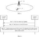
- FIG. 1 is an application scenario diagram of a technical solution of this application according to an embodiment of this application.
- FIG. 1 shows only one terminal device 10 and one network device 20. Actually, more terminal devices 10 and network devices 20 may be further included.
- the terminal device 10 communicates with the network device 20 through a wireless interface.
- the network device in this application may be an evolved NodeB (evolved NodeB, eNB) in long term evolution (Long Term Evolution, LTE) or enhanced Long Term Evolution (evolved Long Term Evolution, eLTE), or a next generation-evolved NodeB (next generation-evolved NodeB, NG-eNB), or may be an access point (Access Point, AP) or a relay node in a WLAN, or may be a gNB in NR. This is not limited herein.
- eNB evolved NodeB
- LTE Long Term Evolution
- eLTE enhanced Long Term Evolution
- NG-eNB next generation-evolved NodeB
- AP Access Point
- WLAN Wireless Local Area Network
- gNB Wireless Local Area Network
- the terminal device (terminal device) in this application may also be referred to as user equipment (User Equipment, UE), a mobile terminal (Mobile Terminal, MT), mobile user equipment, or the like, and may communicate with one or more core networks by using a radio access network (for example, Radio Access Network, RAN).
- the user equipment may be a mobile terminal, for example, a mobile phone (or referred to as a "cellular" phone) and a computer with a mobility capability.
- the user equipment may be a portable, pocket-sized, handheld, computer built-in, or vehicle-mounted mobile apparatus.
- the user equipment may be a communications device in machine type communication MTC.
- terminal devices in the embodiments of this application may include entire user equipments that are independently sold or chips in these entire user equipments.
- a plurality of' in this specification means two or more than two.
- the term "and/or” describes an association relationship for describing associated objects and represents that three relationships may exist.
- a and/or B may represent the following three cases: Only A exists, both A and B exist, and only B exists.
- the character "/" generally represents an "or" relationship between the associated objects.
- CSI in this specification is information determined by the terminal device based on a reference signal (reference signal, RS), and the CSI may include a type of information or any combination of information of: a channel quality indicator (channel quality indicator, CQI), a precoding matrix indicator (precoding matrix indicator, PMI), and a rank indicator (rank indicator, RI).
- a reference signal reference signal
- RS reference signal
- the terminal device performs singular value decomposition (Singular value decomposition, SVD) on a channel matrix, and selects, from a codebook, a matrix having a minimum mean square error with a right singular value matrix obtained after the SVD, as a precoding matrix.
- the precoding matrix is used to determine a mapping relationship between a layer (layer) and an antenna port, and reflects a spatial characteristic of a channel.
- a quantity of data streams simultaneously transmitted in space is a quantity of layers (layer), that is, a quantity of data streams that can be independently and concurrently transmitted.
- the terminal device maps a codeword (codeword) to a plurality of data streams through layer mapping.
- the terminal device performs SVD decomposition on the channel matrix to obtain a channel matrix rank.
- the channel matrix rank may be a maximum value of a value of the RI.
- the channel matrix rank may be 2, and the RI that is fed back may be 1.
- This application provides transmission methods in the following embodiments to transmit the CSI more flexibly and quickly.
- transmission methods for specific explanation and description of the transmission method, refer to the following embodiments.
- FIG. 2 is a flowchart of a channel state information transmission method according to an embodiment of this application. As shown in FIG. 2 , the method in this embodiment may include the following steps.
- Step 101 A network device sends first higher layer signaling to a terminal device.
- the terminal device receives the first higher layer signaling sent by the network device.
- the first higher layer signaling is used to indicate a first physical uplink control channel (Physical uplink control channel, PUCCH), and the first PUCCH is a channel used to periodically report CSI.
- the first higher layer information may be used to indicate one or more of information such as a resource position of the first PUCCH, a format (format), a periodicity, and a resource index.
- the first higher layer signaling may be radio resource control (RRC) signaling.
- RRC radio resource control
- the terminal device receives the downlink control information (Downlink control information, DCI) sent by the network device, and the downlink control information is used to schedule a physical downlink shared channel PDSCH.
- DCI downlink control information
- the DCI in this embodiment is different from downlink control information (for example, DCI format 0_1) used for uplink scheduling.
- the DCI in this embodiment is used for downlink scheduling, that is, used for scheduling the PDSCH.
- the DCI used for downlink scheduling may be represented as DL DCI.
- the terminal device may send the feedback information to the network device by using the following second PUCCH.
- the second PUCCH is indicated by the downlink control information or second higher layer signaling, a time at which the CSI is sent by using the second PUCCH is earlier than a time at which the CSI is sent by using a first PUCCH in a next periodicity, and the next periodicity is a next adjacent periodicity of a periodicity in which the current first PUCCH is located.
- the second higher layer signaling may be the radio resource control (RRC) signaling.
- the periodicity in which the current first PUCCH is located is explained and described.
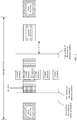
- the periodicity may be shown in FIG. 3 , and starts from the first symbol of the leftmost first PUCCH and ends up with the first symbol of the last-side first PUCCH.
- the first PUCCHs are marked by using diagonal lines that tilt to the left.
- the current first PUCCH is the leftmost first PUCCH shown in FIG. 3
- the first PUCCH in the next periodicity is the rightmost first PUCCH shown in FIG. 3 .
- the terminal device After determining the CSI, the terminal device sends the CSI by using the first PUCCH and the second PUCCH, or sends the CSI by using the second PUCCH.
- the first PUCCH and the second PUCCH For a position relationship between the first PUCCH and the second PUCCH, refer to FIG. 3 .
- the second PUCCH (marked by using horizontal lines) is located between two first PUCCHs, that is, the time domain position of the second PUCCH is earlier than that of the first PUCCH in the next periodicity, so that CSI can be reported quickly.
- the terminal device receives first higher layer signaling sent by the network device.
- the first higher layer signaling is used to configure the first PUCCHs (only two first PUCCHs are shown in the figure) shown in FIG. 3 for the terminal device.
- the terminal device receives, at a position shown in FIG. 3 , DL DCI sent by the network device, and receives and measures the CSI-RS resources shown in FIG. 3 , to determine the CSI.
- the terminal device sends the CSI to the network device by using the second PUCCH shown in FIG. 3 . As shown in FIG.
- the CSI-RS resource may be used to determine channel quality of a frequency band not at the frequency domain position of the PDSCH.
- the terminal device receives the DCI sent by the network device, where the DCI is used to schedule the PDSCH; and the terminal device receives and measures the RS resource, to determine the CSI, and sends the CSI by using the first PUCCH and the second PUCCH, or sends the CSI by using the second PUCCH. Because the second PUCCH is indicated by the DCI used to schedule the PDSCH or the second higher layer signaling, and the time domain position of the second PUCCH is earlier than that of the first PUCCH in the next periodicity, the CSI can be reported flexibly and quickly.
- the CSI transmitted in step 103 is determined by the terminal device based on the RS resource, and the RS resource includes at least one of the CSI-RS resource, a physical downlink shared channel data demodulation reference signal (PDSCH DMRS) resource, and a physical downlink control channel demodulation reference signal (PDCCH DMRS) resource.
- the terminal device measures the CSI-RS resource and the PDSCH DMRS resource, and determines the CSI based on measurement results of the CSI-RS resource and the PDSCH DMRS resource.
- the CSI-RS resource is a periodic CSI-RS resource.
- PDCCH DMRS The PDCCH DMRS is transmitted along with a PDCCH.
- a PDCCH DMRS sent only on a resource element group (Resource Element Group, REG) carrying the PDCCH is referred to as a narrowband DMRS.
- PDCCH DMRSs sent on all REGs of consecutive RBs of a CORESET blindly detected by the terminal device are referred to as wideband DMRSs.
- Channel estimation is performed on the physical downlink shared channel by using the PDCCH DMRS, and an obtained result is used for coherent detection and demodulation.
- the PDSCH DMRS is transmitted along with the PDSCH.
- the PDSCH DMRS is used to perform channel estimation on the physical downlink shared channel, and an obtained result is used for coherent detection and demodulation.
- the terminal device may further send indication information to the network device.
- the indication information is used to indicate an index of the RS resource used to determine the CSI.
- the first N bits in the CSI may be used to indicate a type of the RS resource used to determine the CSI.
- a mapping relationship of the first two bits in the CSI is as follows: '00' indicates that the RS resource used to determine the CSI is the PDSCH DMRS, '01' indicates that the RS resource used to determine the CSI is the PDCCH DMRS, '10' indicates that the RS resource used to determine the CSI is the CSI-RS resource 1, and '11' indicates the RS resource used to determine the CSI is the CSI-RS resource 2.
- the terminal device obtains one piece of CSI based on each of the four reference signals, selects one piece of CSI with best channel quality from the four pieces of CSI, sends the CSI on the second PUCCH, and indicates, by using the first two bits in the CSI, a type of a reference signal on which the CSI is based.
- the network device determines, based on an indication of the first two bits, the reference signal corresponding to the CSI, to determine channel quality of a corresponding bandwidth based on a frequency domain resource occupied by the reference signal.
- the RS resource used to determine the CSI may be any one or a combination of the CSI-RS resource, the PDSCH DMRS resource, and the PDCCH DMRS resource. The following explains and describes selection of the RS resource used to determine the CSI.
- the last time domain symbol in which the CSI-RS resource is located is before the second PUCCH by a first preset quantity of time domain symbols, and the first preset quantity is greater than 0.
- the first preset quantity may be a CSI calculation delay requirement Z', where a value of Z' may be 8, 11, 21, 36, or the like, and a unit is a time domain symbol.
- the CSI-RS resource before the second PUCCH by the first preset quantity of time domain symbols is selected for receiving and measurement, to determine the CSI.
- a resource range in which the CSI-RS resource is selected is referred to as a resource selection window.
- the last time domain symbol W last of the resource selection window that is, the first preset quantity of time domain symbols before the second PUCCH, may be determined.
- For a position of the last time domain symbol W last in the resource selection window refer to FIG. 3 .
- a time domain symbol in which the CSI-RS resource is located is not earlier than the first time domain symbol in the DCI.
- the CSI-RS resource not earlier than the first time domain symbol of the DCI is selected for receiving and measurement, to determine the CSI.
- the first time domain symbol W first of the resource selection window that is, the first time domain symbol of the DCI, may be determined.
- a position of the first time domain symbol W first of the resource selection window may be a position of a second dashed-line box from left to right shown in FIG. 3 .
- the CSI-RS resource is not earlier than a next time domain symbol of the last time domain symbol of a closest first PUCCH, and the closest first PUCCH is before the second PUCCH and is closest to the time domain position of the second PUCCH.
- the CSI-RS resource not earlier than the next time domain symbol of the last time domain symbol of the closest first PUCCH is selected for receiving and measurement, to determine the CSI.
- the closest first PUCCH is before the second PUCCH and closest to the time domain position of the second PUCCH.
- the first time domain symbol W first of the resource selection window may be determined.
- a position of the first time domain symbol W first of the resource selection window may be a position of a first dashed-line box from left to right shown in FIG. 3 .
- the first time domain symbol in which the CSI-RS resource is located is not earlier than the second PUCCH by a second preset quantity
- the second preset quantity is a sum of the first preset quantity and a third preset quantity
- the third preset quantity is greater than 0.
- the first time domain symbol W first and the last time domain symbol W last of the resource selection window are determined in the foregoing manner 1 and manner 2, or in the foregoing manner 1 and manner 3.
- the resource selection window is determined based on min ⁇ W config ,W last- W first ⁇ , and the CSI-RS resource in the resource selection window is selected for receiving and measurement, to determine the CSI.
- a maximum window length limit may be further set to min ⁇ W config , W last -W first ⁇ in this embodiment of this application. If there are excessive CSI-RS resources in the window length W last -W first , a processing time of the terminal device is excessively long, and the terminal device cannot perform timely reporting on a second PUCCH resource indicated by the DCI for downlink scheduling, then the network device limits an actual window length by using preconfigured duration W config . In this way, the terminal device can process, in time, a CSI-RS resource that falls within the window and report the CSI in time.
- the window length limitation affects only a W first position of the window, because an end symbol of the window is determined based on the time Z' that is required by the terminal device for processing.
- the CSI-RS resource when the RS resource used to determine the CSI is the CSI-RS resource, the CSI-RS resource may further meet the following condition.
- the CSI-RS resource may further be sifted out in the following several manners (manner 5 to manner 7), to receive and measure the CSI-RS resource sifted out, to determine the CSI.
- the CSI-RS resource used to determine the CSI and the PDSCH DMRS used to determine the CSI are in a non-quasi co-location (Quasi co-location, QCL) relationship, and the CSI-RS resource used to determine the CSI and the PDCCH DMRS used to determine the CSI are in a non-QCL relationship.
- the CSI-RS resource that is in the non-QCL relationship with the PDCCH DMRS used to determine the CSI or the PDSCH DMRS is selected for receiving and measurement, to determine the CSI.
- the large-scale parameter includes one or more of parameters such as a delay spread, a Doppler spread, a frequency offset, an average received power, and the like.
- a given CSI-RS antenna port and a downlink shared channel DMRS are configured as being QCLed.
- the terminal device may assist the downlink shared channel DMRS in channel estimation based on the large-scale channel parameter information obtained based on the CSI-RS.
- a relationship between receive beams of different signals or between different channels is determined by using a QCL type (including QCL Type A, QCL Type B, QCL Type C, and QCL Type D).
- a receive beam of the PDSCH DMRS may be different from a receive beam of the CSI-RS.
- the CSI is reported in the manner 5 based on CSI-RS resources that have a relationship different from the QCL relationship between PDSCH DMRSs, so that channel state quality of different beams (beam) can be obtained. This helps switch a communication link to a beam with better channel quality.
- a CSI-RS resource is selected for receiving and measurement, to determine the CSI, where the CSI-RS resource and a PDSCH DMRS or a PDCCH DMRS used to determine the CSI have different QCL reference source signals.
- the PDSCH DMRS and the CSI-RS resource 1 have a same QCL reference source signal, and in this case, the CSI-RS resource 1 is not selected as the CSI-RS resource used to determine CSI.
- the CSI-RS resource may include a CSI-RS resource that incompletely overlaps or does not overlap a frequency domain resource on which a PDSCH is located.
- the CSI-RS resource is selected for receiving and measurement, to determine the CSI, where the CSI-RS resource incompletely overlaps or does not overlap a frequency domain resource on which the PDSCH is located.
- channel quality in an RB occupied by the PDSCH may be obtained by measuring the PDSCH DMRS by using the existing solution, and for channel quality outside the RB occupied by the PDSCH, the foregoing manner 6 may be used to measure the CSI-RS resource whose occupied bandwidth incompletely overlaps or does not overlap the RB occupied by the PDSCH DMRS.
- the RB occupied by the CSI-RS resource is a fullband, the PDSCH scheduled by the downlink DCI performs rate matching on an RE occupied by the CSI-RS.
- a CSI-RS resource that falls within the window is determined based on the frequency domain position of the PDSCH scheduled by the downlink DCI, for example, a CSI-RS resource that incompletely/partially overlaps the RB occupied by the PDSCH in frequency domain.
- a CSI-RS resource with a quantity of ports less than or equal to a preset threshold is selected, from CSI-RS resources with different quantities of antenna ports, for receiving and measurement, to determine the CSI.
- the CSI-RS resources with different quantities of antenna ports are configured by the network device by using third higher layer signaling.
- the third higher layer signaling may be radio resource control (RRC) signaling.
- the terminal device may alternatively select a single-port (port) CSI-RS resource, or measure only a CSI-RS resource whose port quantity is equal to a preconfigured port quantity.
- the network device configures, by using the third higher layer signaling, a port quantity corresponding to the CSI-RS resource.
- the network device preconfigures one port quantity by using the third higher layer signaling, and the terminal device performs sifting, based on the port quantity, on CSI-RS resources that fall within the resource selection window, and selects a CSI-RS resource that matches the preconfigured port quantity for receiving and measurement, to determine the CSI.
- the CSI-RS resource is selected in one or more of the foregoing manner 1 to manner 7. It is assumed that the selected CSI-RS resource is M CSI-RS resources.
- the CSI-RS resources used to determine the CSI may be further sifted out by using the following steps. In a specific implementation, from the M CSI-RS resources, min ⁇ N,M ⁇ CSI-RS resources whose time domain positions are closest to the second physical uplink control channel are selected, where N is a fourth preset quantity. The CSI is determined based on the closest min ⁇ N,M ⁇ CSI-RS resources.
- the quantity of the CSI-RS resources used to determine the CSI is selected by using the fourth preset quantity.
- the network device may further configure, for the terminal device, one or more third PUCCHs whose periodicities are different from the periodicity of the first PUCCH.
- Step 201 A network device sends first higher layer signaling to a terminal device.
- this first higher layer signaling may be further used to indicate one or more third PUCCHs.
- the third PUCCH is a channel used to periodically report CSI, and each third PUCCH and a first PUCCH belong to different periodicities.
- one third PUCCH is used as an example.
- the third PUCCH is used to periodically report the CSI, and the third PUCCH and the first PUCCH belong to different periodicities.
- Different configuration identifiers may be used to distinguish between the first PUCCH and the third PUCCH, and the configuration identifier may be bound to an identifier of a CSI reporting configuration.
- Each CSI reporting configuration is bound to one CSI-RS resource configuration, and each CSI-RS resource configuration includes a maximum of 16 CSI-RS resource sets.
- One CSI-RS resource set is a periodic CSI-RS resource set, and the periodic CSI-RS resource set includes a plurality of CSI-RS resources.
- Each CSI reporting configuration is bound to the first PUCCH, or is bound to the third PUCCH.
- a configuration identifier of the first PUCCH is different from a configuration identifier of the third PUCCH
- an identifier of a CSI reporting configuration bound to the first PUCCH is different from an identifier of a CSI reporting configuration bound to the third PUCCH.
- a CSI-RS resource bound to the configuration identifier of the first PUCCH is referred to as a first CSI-RS resource
- a CSI-RS resource bound to the configuration identifier of the third PUCCH is referred to as a second CSI-RS resource.
- the first CSI-RS resource is not earlier than a next time domain symbol of the last time domain symbol of a closest first PUCCH
- the closest first PUCCH is before the second PUCCH and is closest to a time domain position of the second PUCCH
- each second CSI-RS resource is not earlier than a next time domain symbol of the last time domain symbol of a closest third PUCCH
- the closest third PUCCH is before the second PUCCH, closest to the time domain position of the second PUCCH, and bound to the second CSI-RS resource.
- Step 202 The network device sends downlink control information to the terminal device.
- the DCI is used to schedule a PDSCH.
- the terminal device may monitor a PDCCH at a semi-statically configured monitoring moment, to receive the DCI used to schedule the PDSCH. After receiving the DCI, the terminal device receives and measures an RS resource, to determine the CSI.
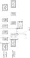
- the CSI may be reported based on periodic CSI-RS resources bound to CSI reporting configurations with a plurality of configuration identifiers, or the CSI may be reported based on periodic CSI-RS resources (for example, the CSI-RS resources in the first row or the CSI-RS resources in the second row in FIG. 4 ) bound to CSI reporting configurations with one configuration identifier.
- the terminal device may receive and measure the first CSI-RS resource and/or the second CSI-RS resource, to determine the CSI.
- Any one of the foregoing manner 1 to manner 7 or a combination thereof may be used as a manner of sifting out the CSI-RS resource used to determine the CSI. For example, as shown in FIG. 5 , it is determined, based on positions of the first PUCCH, the second PUCCH, and the third PUCCH, to select the CSI-RS resource in the dashed box for receiving and measurement, to determine the CSI.
- Step 203 The terminal device sends the CSI by using the first physical uplink control channel and the second physical uplink control channel, sends the CSI by using the third physical uplink control channel and the second physical uplink control channel, or sends the CSI by using the second physical uplink control channel.
- the time domain position at which the second physical uplink control channel is located is earlier than a time domain position at which any third physical uplink control channel is located.
- the terminal device receives the DCI sent by the network device, where the DCI is used to schedule the PDSCH.
- the terminal device receives and measures the RS resource, to determine the CSI, and sends the CSI by using the first physical uplink control channel and the second physical uplink control channel, sends the CSI by using the third physical uplink control channel and the second physical uplink control channel, or sends the CSI by using the second physical uplink control channel.
- the second PUCCH is indicated by the DCI used to schedule the PDSCH or second higher layer signaling, and the time domain position of the second PUCCH is earlier than those of a first PUCCH and a second PUCCH in a next periodicity, the CSI can be reported flexibly and quickly.
- the CSI-RS resource is sifted out in any one of the manner 1 to the manner 7 in the foregoing embodiment or a combination thereof, and the CSI-RS resource sifted out is received and measured, to determine the CSI.
- a plurality of pieces of CSI may be further determined based on resource positions of a plurality of CSI-RS resources, and the CSI reported by using the second PUCCH is determined based on power offsets of the plurality of pieces of CSI and the plurality of CSI-RS resources.
- the CSI may be a CQI.
- the network device may configure, by using a higher layer signaling power control offset (powerControlOffset), a power offset between an RE on which the CSI-RS resource is located and an RE on which the PDSCH is located.
- a value of the power offset is ⁇ -8, ..., 15 ⁇ , and a unit is dB. If the power offset configured by using the higher layer signaling is -3 dB, power of an RE on which a PDSCH DMRS resource is located is one time higher than power of the RE in which the CSI-RS resource is located.
- CSI obtained based on the PDSCH DMRS resource is CQI A
- CSI obtained based on the CSI-RS resource is also CQI A
- a power offset further needs to be considered for the CSI obtained based on the CSI-RS resource, to obtain CQI A+3. This indicates that channel quality of the CSI-RS resource is higher than channel quality of the PDSCH DMRS resource.
- the solutions of the CSI transmission method provided in the embodiments of this application are separately described from perspectives of the terminal device, the network device, and interaction between the terminal device and the network device.
- the communications apparatus for example, the foregoing terminal device and the network device, includes corresponding hardware structures and/or software modules for performing the functions.
- a person skilled in the art should easily be aware that, in combination with units and algorithm steps of the examples described in the embodiments disclosed in this specification, this application can be implemented by hardware or a combination of hardware and computer software. Whether a function is performed by hardware or hardware driven by computer software depends on particular applications and design constraints of the technical solutions. A person skilled in the art may use different methods to implement the described functions for each particular application, but it should not be considered that the implementation goes beyond the scope of this application.
- the communications apparatus when the communications apparatus implements a corresponding function by using a software module, the communications apparatus may include a receiving module 501, a processing module 502, and a sending module 503, as shown in FIG. 6A .
- the communications apparatus may be configured to perform an operation of the terminal device in FIG. 2 .
- the receiving module 501 is configured to receive first higher layer signaling sent by a network device, where the first higher layer signaling is used to indicate a first physical uplink control channel, and the first physical uplink control channel is a channel used to periodically report channel state information CSI.
- the receiving module 501 is further configured to receive downlink control information sent by the network device, where the downlink control information is used to schedule a physical downlink shared channel.
- the processing module 502 is configured to send the CSI by using the first physical uplink control channel and a second physical uplink control channel and by using the sending module 502, or send the CSI by using the second physical uplink control channel and by using the sending module 503.
- the second physical uplink control channel is indicated by the downlink control information or second higher layer signaling, a time at which the CSI is sent by using the second physical uplink control channel is earlier than a time at which the CSI is sent by using a first physical uplink control channel in a next periodicity, and the next periodicity is a next periodicity of a periodicity in which the current first physical uplink control channel is located.
- the communications apparatus can report the CSI flexibly and quickly.
- a time domain position at which the second physical uplink control channel is located is earlier than a time domain position at which any third physical uplink control channel is located, each third physical uplink control channel is a channel used to periodically report the CSI, and the third physical uplink control channel and the first physical uplink control channel belong to different periodicities.
- the processing module 502 is further configured to determine the CSI based on a reference signal RS resource, where the RS resource includes at least one of a CSI-RS resource, a physical downlink shared channel data demodulation reference signal PDSCH DMRS resource, and a physical downlink control channel demodulation reference signal PDCCH DMRS resource.
- the sending module 503 is further configured to send indication information to the network device, where the indication information is used to indicate an index of the RS resource used to determine the CSI.
- the RS resource used to determine the CSI is the CSI-RS resource
- the last time domain symbol in which the CSI-RS resource is located is before the second physical uplink control channel by a first preset quantity of time domain symbols, and the first preset quantity is greater than 0.
- the RS resource used to determine the CSI is the CSI-RS resource; and a time domain symbol in which the CSI-RS resource is located is not earlier than the first time domain symbol of the downlink control information; or the CSI-RS resource includes a first CSI-RS resource and a second CSI-RS resource, the first CSI-RS resource is not earlier than a next time domain symbol of the last time domain symbol of a closest first physical uplink control channel, the closest first physical uplink control channel is before the second physical uplink control channel and is closest to a time domain position of the second physical uplink control channel, each second CSI-RS resource is not earlier than a next time domain symbol of the last time domain symbol of a closest third physical uplink control channel, and the closest third physical uplink control channel is before the second physical uplink control channel, closest to the time domain position of the second physical uplink control channel, and bound to the second CSI-RS resource.
- the RS resource used to determine the CSI is the CSI-RS resource
- the first time domain symbol in which the CSI-RS resource is located is not earlier than the second physical uplink control channel by a second preset quantity of time domain symbols
- the second preset quantity is a sum of the first preset quantity and a third preset quantity
- the third preset quantity is greater than 0.
- the RS resource used to determine the CSI is the CSI-RS resource
- the CSI-RS resource is M CSI-RS resources
- the processing module 502 is further configured to: select, from the M CSI-RS resources, min ⁇ N,M ⁇ CSI-RS resources whose time domain positions are closest to the second physical uplink control channel, where N is a fourth preset quantity; and determine the CSI based on the closest min ⁇ N,M ⁇ CSI-RS resources.
- the receiving module 501, the processing module 502, and the sending module 503 in the communications apparatus may further implement other operations or functions of the terminal device in the foregoing method. Details are not described herein again.
- the communications apparatus shown in FIG. 6A may be further configured to perform an operation of the network device in FIG. 2 .
- the sending module 503 is configured to send first higher layer signaling to a terminal device, where the first higher layer signaling is used to indicate a first physical uplink control channel, and the first physical uplink control channel is a channel used to periodically report channel state information CSI.
- the sending module 503 is further configured to send downlink control information to the terminal device, where the downlink control information is used to schedule a physical downlink shared channel.
- the processing module 502 is configured to control the receiving module 501 to receive, by using the first physical uplink control channel and a second physical uplink control channel, the CSI sent by the terminal device, or receive, by using a second physical uplink control channel, the CSI sent by the terminal device.
- the second physical uplink control channel is indicated by the downlink control information or second higher layer signaling, a time at which the CSI is received by using the second physical uplink control channel is earlier than a time at which the CSI is received by using a first physical uplink control channel in a next periodicity, and the next periodicity is a next periodicity of a periodicity in which the current first physical uplink control channel is located.
- the communications apparatus can report the CSI flexibly and quickly.
- the receiving module 501 is further configured to receive indication information sent by the terminal device, where the indication information is used to indicate an index of an RS resource used to determine the CSI; and the RS resource includes a resource and includes at least one of a CSI-RS resource, a physical downlink shared channel data demodulation reference signal PDSCH DMRS resource, and a physical downlink control channel demodulation reference signal PDCCH DMRS resource.
- the receiving module 501, the processing module 502, and the sending module 503 in the communications apparatus may further implement other operations or functions of the network device in the foregoing method. Details are not described herein again.
- FIG. 6B is another possible schematic structural diagram of the communications apparatus in the foregoing embodiments.
- the communications apparatus includes a transceiver 504 and a processor 505, as shown in FIG. 6B .
- the communications apparatus further includes a memory 506.
- the memory 506 is configured to be coupled to the processor 505, and the memory stores a computer program necessary for the communications apparatus.
- the processor 505 is configured to perform another operation or function of a terminal device.
- the transceiver 504 is configured to implement communication between the communications apparatus and a network device.
- the processor 505 is configured to perform another operation or function of the network device.
- the transceiver 504 is configured to implement communication between the communications apparatus and the terminal device.
- the controller/processor configured to perform the foregoing CSI transmission method in this application may be a central processing unit (CPU), a general-purpose processor, a digital signal processor (DSP), an application-specific integrated circuit (ASIC), a field programmable gate array (FPGA) or another programmable logic device, a transistor logical device, a hardware component, or any combination thereof.
- the controller/processor may implement or execute various example logical blocks, modules, and circuits described with reference to content disclosed in this application.
- the processor may alternatively be a combination of implementing a computing function, for example, a combination of one or more microprocessors or a combination of a DSP and a microprocessor.
- the method or algorithm steps described with reference to the content disclosed in this application may be implemented by hardware, or may be implemented by a processor by executing software instructions.
- the software instructions may include a corresponding software module.
- the software module may be located in a RAM memory, a flash memory, a ROM memory, an EPROM memory, an EEPROM memory, a register, a hard disk, a removable hard disk, a CD-ROM, or a storage medium of any other form known in the art.
- a storage medium is coupled to a processor, so that the processor can read information from the storage medium or write information into the storage medium.
- the storage medium may alternatively be a component of the processor.
- the processor and the storage medium may also be located in an ASIC.
- the ASIC may be located in the radio access network device.
- the processor and the storage medium may alternatively exist in the radio access network device as discrete components.
- All or some of the foregoing embodiments may be implemented by software, hardware, firmware, or any combination thereof.
- the computer program product includes one or more computer instructions.
- the computer may be a general-purpose computer, a special-purpose computer, a computer network, or another programmable apparatus.
- the computer instructions may be stored in a computer-readable storage medium or may be transmitted from one computer-readable storage medium to another computer-readable storage medium.
- the computer instructions may be transmitted from one website, computer, server, or data center to another website, computer, server, or data center in a wired (for example, a coaxial cable, an optical fiber, or a digital subscriber line (DSL)) or wireless (for example, infrared, radio, or microwave) manner.
- the computer-readable storage medium may be any usable medium accessible by a computer, or a data storage device, such as a server or a data center, integrating one or more usable media.
- the usable medium may be a magnetic medium (for example, a floppy disk, a hard disk, or a magnetic tape), an optical medium (for example, a DVD), a semiconductor medium (for example, a solid state drive (Solid State Disk, SSD)), or the like.
- a magnetic medium for example, a floppy disk, a hard disk, or a magnetic tape
- an optical medium for example, a DVD
- a semiconductor medium for example, a solid state drive (Solid State Disk, SSD)
Landscapes
- Engineering & Computer Science (AREA)
- Signal Processing (AREA)
- Computer Networks & Wireless Communication (AREA)
- Quality & Reliability (AREA)
- Mobile Radio Communication Systems (AREA)
Applications Claiming Priority (2)
| Application Number | Priority Date | Filing Date | Title |
|---|---|---|---|
| CN201811348263.6A CN111181704B (zh) | 2018-11-13 | 2018-11-13 | 信道状态信息的传输方法和装置 |
| PCT/CN2019/115283 WO2020098522A1 (fr) | 2018-11-13 | 2019-11-04 | Procédé et appareil de transmission d'informations d'état de canal |
Publications (1)
| Publication Number | Publication Date |
|---|---|
| EP3869723A1 true EP3869723A1 (fr) | 2021-08-25 |
Family
ID=70622276
Family Applications (1)
| Application Number | Title | Priority Date | Filing Date |
|---|---|---|---|
| EP19883603.3A Withdrawn EP3869723A1 (fr) | 2018-11-13 | 2019-11-04 | Procédé et appareil de transmission d'informations d'état de canal |
Country Status (4)
| Country | Link |
|---|---|
| US (1) | US20210266926A1 (fr) |
| EP (1) | EP3869723A1 (fr) |
| CN (1) | CN111181704B (fr) |
| WO (1) | WO2020098522A1 (fr) |
Families Citing this family (12)
| Publication number | Priority date | Publication date | Assignee | Title |
|---|---|---|---|---|
| WO2021255497A1 (fr) * | 2020-06-16 | 2021-12-23 | Telefonaktiebolaget Lm Ericsson (Publ) | Adaptation de liaison à boucle extérieure rapide |
| US11832330B2 (en) * | 2020-06-26 | 2023-11-28 | Qualcomm Incorporated | Beam failure detection for full-duplex communication |
| WO2022032691A1 (fr) * | 2020-08-14 | 2022-02-17 | 华为技术有限公司 | Procédé, appareil et système de configuration de rapport de mesure |
| CN115175326B (zh) * | 2021-04-02 | 2026-02-27 | 维沃移动通信有限公司 | 上行传输方法、装置、终端、网络侧设备和存储介质 |
| CN115208529B (zh) * | 2021-04-12 | 2024-05-07 | 维沃移动通信有限公司 | 信号传输方法、终端及网络侧设备 |
| CN115333688B (zh) * | 2021-05-10 | 2024-12-03 | 展讯通信(上海)有限公司 | 通信处理方法、装置、存储介质、芯片及模组设备 |
| WO2023004754A1 (fr) * | 2021-07-30 | 2023-02-02 | Zte Corporation | Systèmes et procédés de conception et de configuration de signalisation de référence |
| CN114221744B (zh) * | 2021-12-03 | 2023-07-07 | 京信网络系统股份有限公司 | 信道状态信息传输方法、装置、终端设备和基站 |
| WO2023236944A1 (fr) * | 2022-06-06 | 2023-12-14 | Mediatek Inc. | Procédé et appareil pour déterminer une fenêtre de mesure de csi et une fenêtre de rapport de csi dans des communications mobiles |
| US20240259061A1 (en) * | 2023-02-01 | 2024-08-01 | Qualcomm Incorporated | Criterion-triggered channel state information reporting configuration |
| WO2024207492A1 (fr) * | 2023-04-07 | 2024-10-10 | 北京小米移动软件有限公司 | Procédés et appareils de détermination de ressources, appareil de communication et support de stockage |
| CN120378913A (zh) * | 2023-08-11 | 2025-07-25 | 中国电信股份有限公司技术创新中心 | 测量方法、用户设备、通信系统和存储介质 |
Family Cites Families (9)
| Publication number | Priority date | Publication date | Assignee | Title |
|---|---|---|---|---|
| JPWO2010032714A1 (ja) * | 2008-09-17 | 2012-02-09 | シャープ株式会社 | 移動通信システム、基地局装置、移動局装置および通信方法 |
| CN103595501B (zh) * | 2012-08-15 | 2016-12-21 | 华为技术有限公司 | 指示信息发送方法和接收方法、基站和用户设备 |
| CN104254994B (zh) * | 2013-04-23 | 2017-10-17 | 华为技术有限公司 | 信道状态信息的发送方法、用户设备、基站及系统 |
| CN110545133B (zh) * | 2013-12-20 | 2022-12-06 | 北京三星通信技术研究有限公司 | 信道状态信息汇报的方法及装置 |
| CN112615707B (zh) * | 2015-06-19 | 2024-04-23 | 北京三星通信技术研究有限公司 | 一种传输上行控制信息的方法 |
| WO2018135795A1 (fr) * | 2017-01-17 | 2018-07-26 | 삼성전자 주식회사 | Procédé et dispositif de notification d'état de canal semi-persistant dans un système de communication mobile |
| CN108112078B (zh) * | 2017-06-20 | 2023-08-29 | 中兴通讯股份有限公司 | 上行数据信道起始符号位置的配置方法、装置及存储介质 |
| US11375391B2 (en) * | 2017-09-29 | 2022-06-28 | Lg Electronics Inc. | Method for reporting aperiodic CSI in wireless communication system and device therefor |
| WO2019120520A1 (fr) * | 2017-12-20 | 2019-06-27 | Telefonaktiebolaget Lm Ericsson (Publ) | Technique de rapport d'informations d'état de canal |
-
2018
- 2018-11-13 CN CN201811348263.6A patent/CN111181704B/zh active Active
-
2019
- 2019-11-04 WO PCT/CN2019/115283 patent/WO2020098522A1/fr not_active Ceased
- 2019-11-04 EP EP19883603.3A patent/EP3869723A1/fr not_active Withdrawn
-
2021
- 2021-05-12 US US17/318,578 patent/US20210266926A1/en not_active Abandoned
Also Published As
| Publication number | Publication date |
|---|---|
| CN111181704B (zh) | 2021-12-10 |
| WO2020098522A1 (fr) | 2020-05-22 |
| US20210266926A1 (en) | 2021-08-26 |
| CN111181704A (zh) | 2020-05-19 |
Similar Documents
| Publication | Publication Date | Title |
|---|---|---|
| EP3869723A1 (fr) | Procédé et appareil de transmission d'informations d'état de canal | |
| JP7364004B2 (ja) | チャネル状態情報の測定目的の指示方法、装置及び通信システム | |
| US12069705B2 (en) | Method for reporting terminal device capability and communications apparatus | |
| US11283503B2 (en) | Communication method and communications apparatus | |
| US11349541B2 (en) | Data transmission method, terminal device, and network device | |
| US11259308B2 (en) | Signal processing method and apparatus | |
| US11595842B2 (en) | Method and apparatus for transmitting channel state information | |
| EP4092918A1 (fr) | Procédé et dispositif de communication | |
| US11438780B2 (en) | Channel sounding information feedback method, user equipment, and base station | |
| CN110786051B (zh) | 传输物理上行控制信道pucch的方法、终端设备和网络设备 | |
| EP3706504A1 (fr) | Procédé et dispositif permettant de déclencher une rétroaction csi et procédé et dispositif de rétroaction csi | |
| EP3528396A1 (fr) | Procédé et dispositif de transmission d'informations | |
| CN110875814A (zh) | 发送和接收混合自动重传请求确认信息的方法、通信装置 | |
| CN109152009B (zh) | 通信方法、终端设备和网络设备 | |
| CN113348711A (zh) | 无线通信中的信道状态评估和上报方案 | |
| JP2024513019A5 (fr) | ||
| US20240314543A1 (en) | Method and apparatus for channel state information (csi) reporting | |
| CN106559167B (zh) | 一种链路自适应的方法及装置 | |
| EP3557810A1 (fr) | Procédé de transmission d'informations, terminal et dispositif côté réseau | |
| EP4195567A1 (fr) | Procédé et appareil de transmission de signal, et support de stockage | |
| AU2017433231A1 (en) | Method for calculating channel quality indicator (CQI), terminal device, and network device | |
| KR102961542B1 (ko) | 단말 디바이스 능력을 보고하기 위한 방법 및 통신 장치 | |
| WO2025067680A1 (fr) | Rapport de qualité de canal de commande et adaptation de liaison | |
| WO2024169693A1 (fr) | Procédé et appareil de transmission de signal, et support de stockage | |
| WO2025066295A1 (fr) | Procédé de traitement d'informations d'état de canal, équipement d'utilisateur, dispositif de réseau et support de stockage |
Legal Events
| Date | Code | Title | Description |
|---|---|---|---|
| STAA | Information on the status of an ep patent application or granted ep patent |
Free format text: STATUS: THE INTERNATIONAL PUBLICATION HAS BEEN MADE |
|
| PUAI | Public reference made under article 153(3) epc to a published international application that has entered the european phase |
Free format text: ORIGINAL CODE: 0009012 |
|
| STAA | Information on the status of an ep patent application or granted ep patent |
Free format text: STATUS: REQUEST FOR EXAMINATION WAS MADE |
|
| 17P | Request for examination filed |
Effective date: 20210520 |
|
| AK | Designated contracting states |
Kind code of ref document: A1 Designated state(s): AL AT BE BG CH CY CZ DE DK EE ES FI FR GB GR HR HU IE IS IT LI LT LU LV MC MK MT NL NO PL PT RO RS SE SI SK SM TR |
|
| RIC1 | Information provided on ipc code assigned before grant |
Ipc: H04L 27/26 20060101ALI20211202BHEP Ipc: H04L 1/12 20060101ALI20211202BHEP Ipc: H04L 5/00 20060101AFI20211202BHEP |
|
| STAA | Information on the status of an ep patent application or granted ep patent |
Free format text: STATUS: THE APPLICATION HAS BEEN WITHDRAWN |
|
| 18W | Application withdrawn |
Effective date: 20211223 |