EP3869868A1 - Verfahren, vorrichtung und system zur ladungsregelbindung - Google Patents
Verfahren, vorrichtung und system zur ladungsregelbindung Download PDFInfo
- Publication number
- EP3869868A1 EP3869868A1 EP20776377.2A EP20776377A EP3869868A1 EP 3869868 A1 EP3869868 A1 EP 3869868A1 EP 20776377 A EP20776377 A EP 20776377A EP 3869868 A1 EP3869868 A1 EP 3869868A1
- Authority
- EP
- European Patent Office
- Prior art keywords
- pcc rule
- network element
- binding
- rule
- qos flow
- Prior art date
- Legal status (The legal status is an assumption and is not a legal conclusion. Google has not performed a legal analysis and makes no representation as to the accuracy of the status listed.)
- Granted
Links
Images





Classifications
-
- H—ELECTRICITY
- H04—ELECTRIC COMMUNICATION TECHNIQUE
- H04L—TRANSMISSION OF DIGITAL INFORMATION, e.g. TELEGRAPHIC COMMUNICATION
- H04L12/00—Data switching networks
- H04L12/02—Details
- H04L12/14—Charging, metering or billing arrangements specially adapted for data communications, e.g. authentication, authorisation and accounting [AAA] framework
- H04L12/1403—Architecture for metering, charging or billing
- H04L12/1407—Policy-and-charging control [PCC] architecture
-
- H—ELECTRICITY
- H04—ELECTRIC COMMUNICATION TECHNIQUE
- H04W—WIRELESS COMMUNICATION NETWORKS
- H04W28/00—Network traffic management; Network resource management
- H04W28/02—Traffic management, e.g. flow control or congestion control
- H04W28/0268—Traffic management, e.g. flow control or congestion control using specific QoS parameters for wireless networks, e.g. QoS class identifier [QCI] or guaranteed bit rate [GBR]
-
- H—ELECTRICITY
- H04—ELECTRIC COMMUNICATION TECHNIQUE
- H04L—TRANSMISSION OF DIGITAL INFORMATION, e.g. TELEGRAPHIC COMMUNICATION
- H04L12/00—Data switching networks
- H04L12/02—Details
- H04L12/14—Charging, metering or billing arrangements specially adapted for data communications, e.g. authentication, authorisation and accounting [AAA] framework
-
- H—ELECTRICITY
- H04—ELECTRIC COMMUNICATION TECHNIQUE
- H04M—TELEPHONIC COMMUNICATION
- H04M15/00—Arrangements for metering, time-control or time indication ; Metering, charging or billing arrangements for voice wireline or wireless communications, e.g. VoIP
- H04M15/66—Policy and charging system
-
- H—ELECTRICITY
- H04—ELECTRIC COMMUNICATION TECHNIQUE
- H04M—TELEPHONIC COMMUNICATION
- H04M15/00—Arrangements for metering, time-control or time indication ; Metering, charging or billing arrangements for voice wireline or wireless communications, e.g. VoIP
- H04M15/80—Rating or billing plans; Tariff determination aspects
- H04M15/8016—Rating or billing plans; Tariff determination aspects based on quality of service [QoS]
-
- H—ELECTRICITY
- H04—ELECTRIC COMMUNICATION TECHNIQUE
- H04M—TELEPHONIC COMMUNICATION
- H04M15/00—Arrangements for metering, time-control or time indication ; Metering, charging or billing arrangements for voice wireline or wireless communications, e.g. VoIP
- H04M15/80—Rating or billing plans; Tariff determination aspects
- H04M15/8038—Roaming or handoff
-
- H—ELECTRICITY
- H04—ELECTRIC COMMUNICATION TECHNIQUE
- H04M—TELEPHONIC COMMUNICATION
- H04M15/00—Arrangements for metering, time-control or time indication ; Metering, charging or billing arrangements for voice wireline or wireless communications, e.g. VoIP
- H04M15/80—Rating or billing plans; Tariff determination aspects
- H04M15/8044—Least cost routing
-
- H—ELECTRICITY
- H04—ELECTRIC COMMUNICATION TECHNIQUE
- H04M—TELEPHONIC COMMUNICATION
- H04M15/00—Arrangements for metering, time-control or time indication ; Metering, charging or billing arrangements for voice wireline or wireless communications, e.g. VoIP
- H04M15/82—Criteria or parameters used for performing billing operations
- H04M15/8228—Session based
-
- H—ELECTRICITY
- H04—ELECTRIC COMMUNICATION TECHNIQUE
- H04W—WIRELESS COMMUNICATION NETWORKS
- H04W28/00—Network traffic management; Network resource management
- H04W28/16—Central resource management; Negotiation of resources or communication parameters, e.g. negotiating bandwidth or QoS [Quality of Service]
- H04W28/24—Negotiating SLA [Service Level Agreement]; Negotiating QoS [Quality of Service]
-
- H—ELECTRICITY
- H04—ELECTRIC COMMUNICATION TECHNIQUE
- H04W—WIRELESS COMMUNICATION NETWORKS
- H04W4/00—Services specially adapted for wireless communication networks; Facilities therefor
- H04W4/24—Accounting or billing
-
- H—ELECTRICITY
- H04—ELECTRIC COMMUNICATION TECHNIQUE
- H04L—TRANSMISSION OF DIGITAL INFORMATION, e.g. TELEGRAPHIC COMMUNICATION
- H04L47/00—Traffic control in data switching networks
- H04L47/10—Flow control; Congestion control
- H04L47/24—Traffic characterised by specific attributes, e.g. priority or QoS
- H04L47/2441—Traffic characterised by specific attributes, e.g. priority or QoS relying on flow classification, e.g. using integrated services [IntServ]
Definitions
- This application relates to the field of communications technologies, and in particular, to a charging rule binding method, a device, and a system.
- the binding mechanism is the procedure that associates a service data flow (defined in a policy and charging control (policy and charging control, PCC) rule by means of the service data flow (service data flow, SDF) template), to the quality of service (quality of service, QoS) flow deemed to transport the service data flow (English:
- PCC policy and charging control
- QoS quality of service
- An existing binding mechanism includes the following three steps:
- Embodiments of this application provide a charging rule binding method, a device, and a system, to resolve a prior-art problem that a RAN device performs incorrect scheduling because PCC rules with a same binding parameter are bound to a same QoS flow.
- a charging rule binding method includes: A session management network element receives a first policy and charging control PCC rule from a policy control network element. The session management network element determines that the first PCC rule is a multi-level PCC rule. The session management network element creates a quality of service flow QoS flow according to the first PCC rule, and binds the first PCC rule to the created QoS flow, where the QoS flow is bound to only the first PCC rule. Based on this solution, in this embodiment of this application, each multi-level PCC rule is bound to a different QoS flow.
- the first PCC rule includes indication information, and the indication information is used to indicate that the first PCC rule is the multi-level PCC rule. That the session management network element determines that the first PCC rule is a multi-level PCC rule includes: The session management network element determines, based on the indication information, that the first PCC rule is the multi-level PCC rule. Based on this solution, the session management network element can determine that the first PCC rule is the multi-level PCC rule.
- the first PCC rule includes N alternative QoS parameter sets, and N is a positive integer greater than 1. That the session management network element determines that the first PCC rule is a multi-level PCC rule includes: The session management network element determines, based on the N alternative QoS parameter sets, that the first PCC rule is the multi-level PCC rule. Based on this solution, the session management network element can determine that the first PCC rule is the multi-level PCC rule.
- a charging rule binding method includes: A session management network element receives a first policy and charging control PCC rule from a policy control network element, where the first PCC rule includes a binding parameter, and a binding parameter at leach level in the binding parameter corresponds to one rank value.
- the session management network element determines, from a PCC rule bound to an existing quality of service flow QoS flow, whether there is a PCC rule in which a binding parameter corresponding to each of all rank values is the same as a binding parameter that is in the first PCC rule and that corresponds to a same rank value in all rank values.
- the session management network element binds the first PCC rule to the existing QoS flow; or if there is no such PCC rule, the session management network element creates a QoS flow according to the first PCC rule, and binds the first PCC rule to the created QoS flow.
- the session management network element creates a QoS flow according to the first PCC rule, and binds the first PCC rule to the created QoS flow.
- a binding parameter at leach level in the binding parameter corresponds to one rank value includes: a binding parameter at leach level in the binding parameter includes one rank value.
- a binding parameter at leach level in the binding parameter corresponds to one rank value includes: the first PCC rule further includes the rank value corresponding to a binding parameter at leach level in the binding parameter.
- a charging rule binding method includes: A session management network element receives a first policy and charging control PCC rule from a policy control network element.
- the session management network element determines, from a PCC rule bound to an existing quality of service flow QoS flow, whether there is a PCC rule in which binding parameters at each level are the same as binding parameters at each level in the first PCC rule respectively. If there is the PCC rule, the session management network element binds the first PCC rule to the existing QoS flow; or if there is no such PCC rule, the session management network element creates a QoS flow according to the first PCC rule, and binds the first PCC rule to the created QoS flow.
- that the session management network element determines, from a PCC rule bound to an existing QoS flow, whether there is a PCC rule in which binding parameters at each level are the same as binding parameters at each level in the first PCC rule respectively includes: The session management network element determines, from the PCC rule bound to the existing QoS flow, whether there is a PCC rule for which a corresponding maximum rank value is the same as a maximum rank value corresponding to the first PCC rule.
- the session management network element determines, from the PCC rule bound to the existing QoS flow, that there is the PCC rule in which the binding parameters are the same as the binding parameters at each level in the first PCC rule respectively; or if there is no such PCC rule for which a corresponding maximum rank value is the same as the maximum rank value corresponding to the first PCC rule, the session management network element determines, from the PCC rule bound to the existing QoS flow, that there is no such PCC rule in which the binding parameters at each level are the same as the binding parameters at each level in the first PCC rule respectively. Based on this solution, the session management network element may determine, from the PCC rule bound to the existing QoS flow, whether there is the PCC rule in which the binding parameters at each level are the same as
- a communications apparatus to implement the foregoing methods.
- the communications apparatus may be a session management network element according to the first aspect, the second aspect, the third aspect, a thirteenth aspect, a seventeenth aspect, or a twentieth aspect, or an apparatus including the session management network element.
- the communications apparatus may be a policy control network element according to a fourteenth aspect, or an apparatus including the policy control network element.
- the communications apparatus includes a corresponding module, unit, or means (means) for implementing the foregoing method.
- the module, unit, or means may be implemented by hardware or software, or implemented by hardware executing corresponding software.
- the hardware or the software includes one or more modules or units corresponding to the foregoing functions.
- a communications apparatus includes a processor and a memory.
- the memory is configured to store a computer instruction, and when the processor executes the instruction, the communications apparatus is enabled to perform the method according to the first aspect.
- the communications apparatus may be a session management network element according to the first aspect, the second aspect, the third aspect, a thirteenth aspect, a seventeenth aspect, or a twentieth aspect, or an apparatus including the session management network element.
- the communications apparatus may be a policy control network element according to a fourteenth aspect, or an apparatus including the policy control network element.
- a communications apparatus includes a processor.
- the processor is configured to: be coupled to a memory, and after reading an instruction from the memory, perform the method according to the first aspect, the second aspect, or the third aspect based on the instruction.
- the communications apparatus may be a session management network element according to the first aspect, the second aspect, the third aspect, a thirteenth aspect, a seventeenth aspect, or a twentieth aspect, or an apparatus including the session management network element.
- the communications apparatus may be a policy control network element according to a fourteenth aspect, or an apparatus including the policy control network element.
- a computer readable storage medium stores an instruction, and when the instruction is run on a computer, the computer may be enabled to perform the method according to the first aspect, the second aspect, the third aspect, a thirteenth aspect, a fourteenth aspect, a seventeenth aspect, or a twentieth aspect.
- a computer program product including an instruction is provided.
- the computer may be enabled to perform the method according to the first aspect, the second aspect, the third aspect, a thirteenth aspect, a fourteenth aspect, a seventeenth aspect, or a twentieth aspect.
- a communications apparatus (for example, the communications apparatus may be a chip or a chip system) is provided.
- the communications apparatus includes a processor, configured to implement the functions according to the first aspect, the second aspect, the third aspect, a thirteenth aspect, a fourteenth aspect, a seventeenth aspect, or a twentieth aspect.
- the communications apparatus further includes a memory.
- the memory is configured to store a program instruction and data that are necessary.
- the communications apparatus is the chip system, the communications apparatus may include a chip, or may include a chip and another discrete component.
- a communications system includes a policy control network element and a session management network element.
- the policy control network element is configured to send a first PCC rule to the session management network element.
- the session management network element is configured to receive the first PCC rule from the policy control network element.
- the session management network element is further configured to: after determining that the first PCC rule is a multi-level PCC rule, create a QoS flow according to the first PCC rule, and bind the first PCC rule to the created QoS flow, where the QoS flow is bound to only the first PCC rule.
- a communications system includes a policy control network element and a session management network element.
- the policy control network element is configured to send a first PCC rule to the session management network element.
- the session management network element is configured to receive the first PCC rule from the policy control network element.
- the first PCC rule includes a binding parameter, and a binding parameter at leach level in the binding parameter corresponds to one rank value.
- the session management network element is further configured to determine, from a PCC rule bound to an existing QoS flow, whether there is a PCC rule in which a binding parameter corresponding to each of all rank values is the same as a binding parameter that is in the first PCC rule and that corresponds to a same rank value in all rank values.
- the session management network element is further configured to bind the first PCC rule to the existing QoS flow; or if there is no such PCC rule, the session management network element is further configured to: create a QoS flow according to the first PCC rule, and bind the first PCC rule to the created QoS flow.
- a communications system includes a policy control network element and a session management network element.
- the policy control network element is configured to send a first PCC rule to the session management network element.
- the session management network element is configured to receive the first PCC rule from the policy control network element.
- the session management network element is further configured to determine, from a PCC rule bound to an existing QoS flow, whether there is a PCC rule in which binding parameters at each level are the same as binding parameters at each level in the first PCC rule respectively.
- the session management network element is further configured to bind the first PCC rule to the existing QoS flow; or if there is no such PCC rule, the session management network element is further configured to: create a QoS flow according to the first PCC rule, and bind the first PCC rule to the created QoS flow.
- a charging rule binding method includes: A session management network element receives a first policy and charging control PCC rule from a policy control network element. The session management network element determines that the first PCC rule needs to be bound to a separate quality of service flow QoS flow. The session management network element creates a QoS flow according to the first PCC rule, and binds the first PCC rule to the created QoS flow. Based on this solution, in this embodiment of this application, each multi-level PCC rule is bound to a different QoS flow.
- the first PCC rule includes indication information. That the session management network element determines that the first PCC rule needs to be bound to a separate QoS flow includes: The session management network element determines, based on the indication information, that the first PCC rule needs to be bound to the separate QoS flow. Based on this solution, the session management network element may determine that the first PCC rule needs to be bound to the separate QoS flow.
- the indication information is any one of the following: the indication information is information indicating that the first PCC rule needs to be bound to the separate QoS flow; the indication information is information indicating that the first PCC rule is a multi-level PCC rule; the indication information is information indicating that a service corresponding to the first PCC rule supports multi-access; the indication information is information indicating that a service corresponding to the first PCC rule is an ultra-reliable low-latency communication URLLC service; the indication information is information indicating that a service corresponding to the first PCC rule requires redundant transmission; the indication information is information indicating that a data network access identifier DNAI in the first PCC rule is different from another DNAI in a current session; the indication information is information indicating that a packet error rate PER in the first PCC rule is different from another PER in a current session; the indication information is information indicating that a service corresponding to the first PCC rule requires a first radio access technology RAT; the indication information is information indicating that a service corresponding to the first PC
- the QoS flow is bound to only the first PCC rule.
- that the QoS flow is bound to only the first PCC rule includes: The session management network element determines, based on a flag bit in the session management network element, that a second PCC rule cannot be bound to the QoS flow.
- a charging rule binding method includes: A policy control network element determines that a first PCC rule needs to be bound to a separate quality of service flow QoS flow.
- the policy control network element sends the first PCC rule to a session management network element, where the first PCC rule includes indication information, and the indication information is used to indicate that the first PCC rule needs to be bound to the separate QoS flow.
- each multi-level PCC rule is bound to a different QoS flow.
- a policy control network element determines that a first PCC rule needs to be bound to a separate QoS flow includes: When one or more of the following conditions are met, the policy control network element determines that the first PCC rule needs to be bound to the separate QoS flow: To ensure that a QoS flow of the first PCC rule is not bound to another PCC rule, the first PCC rule is a multi-level PCC rule; a service corresponding to the first PCC rule supports multi-access; a service corresponding to the first PCC rule is an ultra-reliable low-latency communication URLLC service; a service corresponding to the first PCC rule requires redundant transmission; a data network access identifier DNAI in the first PCC rule is different from another DNAI in a current session; a packet error rate PER in the first PCC rule is different from another PER in a current session; a service corresponding to the first PCC rule requires a first radio access technology RAT; a maximum bit rate in the first PCC rule is greater
- a communication method includes: A policy control network element sends a first policy and charging control PCC rule to a session management network element.
- the session management network element receives the first PCC rule from the policy control network element.
- the session management network element determines that the first PCC rule needs to be bound to a separate quality of service flow QoS flow.
- the session management network element creates a QoS flow according to the first PCC rule, and binds the first PCC rule to the created QoS flow.
- a communications system includes a session management network element and a policy control network element.
- the policy control network element is configured to send a first policy and charging control PCC rule to the session management network element.
- the session management network element is configured to receive the first PCC rule from the policy control network element.
- the session management network element is further configured to determine that the first PCC rule needs to be bound to a separate quality of service flow QoS flow.
- the session management network element is further configured to: create a QoS flow according to the first PCC rule, and bind the first PCC rule to the created QoS flow.
- a charging rule binding method includes: A session management network element receives a first policy and charging control PCC rule from a policy control network element, where the first PCC rule includes a binding parameter.
- the session management network element determines, from an existing quality of service flow QoS flow, whether there is a QoS flow for which a binding parameter is the same as the binding parameter in the first PCC rule. If there is the QoS flow, the session management network element binds the first PCC rule to the existing QoS flow; or if there is no such QoS flow, the session management network element creates a QoS flow according to the first PCC rule, and binds the first PCC rule to the created QoS flow.
- that the session management network element determines, from an existing QoS flow, whether there is a QoS flow for which a binding parameter is the same as the binding parameter in the first PCC rule includes: When the session management network element determines, from a PCC rule bound to the existing QoS flow, that there is a second PCC rule in which a value of a binding parameter of a policy control part is the same as a value of a binding parameter of a policy control part in the first PCC rule, and a value of a binding parameter of an alternative QoS parameter set part in the second PCC rule is the same as a value of a binding parameter of an alternative QoS parameter set part in the first PCC rule, the session management network element determines, from the existing quality of service flow QoS flow, that there is the QoS flow for which the binding parameter is the same as the binding parameter in the first PCC rule.
- the binding parameter in this embodiment of this application includes an alternative QoS parameter set.
- a communication method includes: A policy control network element sends a first policy and charging control PCC rule to a session management network element, where the first PCC rule includes a binding parameter.
- the session management network element receives the first PCC rule from the policy control network element, and determines, from an existing quality of service flow QoS flow, whether there is a QoS flow for which a binding parameter is the same as the binding parameter in the first PCC rule.
- the session management network element binds the first PCC rule to the existing QoS flow; or if there is no such QoS flow, the session management network element creates a QoS flow according to the first PCC rule, and binds the first PCC rule to the created QoS flow.
- the eighteenth aspect refer to the technical effect of the seventeenth aspect. Details are not described herein again.
- a communications system includes a policy control network element and a session management network element.
- the policy control network element is configured to send a first policy and charging control PCC rule to the session management network element, where the first PCC rule includes a binding parameter.
- the session management network element is configured to: receive the first PCC rule from the policy control network element, and determine, from an existing quality of service flow QoS flow, whether there is a QoS flow for which a binding parameter is the same as the binding parameter in the first PCC rule.
- the session management network element is further configured to: if there is the QoS flow, bind the first PCC rule to the existing QoS flow; or if there is no such QoS flow, create a QoS flow according to the first PCC rule, and bind the first PCC rule to the created QoS flow.
- a charging rule binding method includes: A session management network element receives a first policy and charging control PCC rule from a policy control network element, where the first PCC rule includes a first binding parameter.
- the session management network element determines that the first PCC rule includes an alternative quality of service QoS parameter set (alternative QoS parameter sets); and in a PCC rule bound to an existing first QoS flow, there is a second PCC rule in which a value of the first binding parameter is the same as a value of the first binding parameter included in the first PCC rule, and the second PCC rule includes an alternative QoS parameter set
- the session management network element binds the first PCC rule to the existing first QoS flow.
- the session management network element determines that the first PCC rule does not include an alternative QoS parameter set; and in a PCC rule bound to an existing second QoS flow, there is a third PCC rule in which a value of the first binding parameter is the same as a value of the first binding parameter included in the first PCC rule, and the third PCC rule does not include an alternative QoS parameter set, the session management network element binds the first PCC rule to the existing second QoS flow.
- one or more PCC rules that include alternative QoS parameter sets may be considered as PCC rules having a same binding parameter, and one or more PCC rules that do not include alternative QoS parameter sets may be considered as PCC rules having a different binding parameter.
- the one or more PCC rules having the same binding parameter can be bound to a same QoS flow, and the one or more PCC rules having the different binding parameters cannot be bound to a same QoS flow. In this way, a problem that a multi-level PCC rule and a single-level PCC rule that have a same binding parameter are bound to a same QoS flow is avoided, thereby further avoiding incorrect scheduling by a RAN device.
- a communication method includes: A policy control network element sends a first policy and charging control PCC rule to a session management network element, where the first PCC rule includes a first binding parameter.
- the session management network element receives the first PCC rule from the policy control network element.
- the session management network element determines that the first PCC rule includes an alternative quality of service QoS parameter set (alternative QoS parameter sets); and in a PCC rule bound to an existing first QoS flow, there is a second PCC rule in which a value of the first binding parameter is the same as a value of the first binding parameter included in the first PCC rule, and the second PCC rule includes an alternative QoS parameter set, the session management network element binds the first PCC rule to the existing first QoS flow.
- alternative QoS parameter sets alternative QoS parameter sets
- the session management network element determines that the first PCC rule does not include an alternative QoS parameter set; and in a PCC rule bound to an existing second QoS flow, there is a third PCC rule in which a value of the first binding parameter is the same as a value of the first binding parameter included in the first PCC rule, and the third PCC rule does not include an alternative QoS parameter set, the session management network element binds the first PCC rule to the existing second QoS flow.
- the twenty-first aspect refer to the technical effect of the twentieth aspect. Details are not described herein again.
- a communications system includes a policy control network element and a session management network element.
- the policy control network element is configured to send a first policy and charging control PCC rule to the session management network element, where the first PCC rule includes a first binding parameter.
- the session management network element is configured to receive the first PCC rule from the policy control network element.
- the session management network element is further configured to: when determining that the first PCC rule includes an alternative quality of service QoS parameter set (alternative QoS parameter sets); and in a PCC rule bound to an existing first QoS flow, there is a second PCC rule in which a value of the first binding parameter is the same as a value of the first binding parameter included in the first PCC rule, and the second PCC rule includes an alternative QoS parameter set, bind the first PCC rule to the existing first QoS flow.
- the session management network element is further configured to: when determining that the first PCC rule does not include an alternative QoS parameter set; and in a PCC rule bound to an existing second QoS flow, there is a third PCC rule in which a value of the first binding parameter is the same as a value of the first binding parameter included in the first PCC rule, and the third PCC rule does not include an alternative QoS parameter set, bind the first PCC rule to the existing second QoS flow.
- the twenty-second aspect refer to the technical effect of the twentieth aspect. Details are not described herein again.
- the PDU session is an association between a terminal device and a data network (data network, DN), and is used to provide a PDU connection service.
- DN data network
- 5G QoS identifier (5G QoS identifier, 5QI)
- the 5QI is a scalar used to index a 5G QoS characteristic.
- the 5QIs include a standardized 5QI, a preconfigured 5QI, and a dynamically allocated 5QI.
- the standardized 5QIs are in a one-to-one correspondence with a group of standardized 5G QoS characteristic values.
- a 5G QoS characteristic value corresponding to the preconfigured 5QI is preconfigured on an access network device.
- a 5G QoS characteristic corresponding to the dynamically allocated 5QI is sent by a core network device to the access network device by using a QoS profile (QoS profile).
- the ARP includes a priority level, a preemption capability, and a preemption vulnerability.
- Guaranteed flow bit rate (guaranteed flow bit rate, GFBR)
- the GFBR represents a bit rate that is expected to be provided for a guaranteed bit rate (guaranteed bit rate, GBR) QoS flow (flow).
- the MFBR is used to limit a bit rate provided for a GBR QoS flow, namely, a maximum bit rate provided for the GBR QoS flow. If the bit rate is exceeded, a data packet can be discarded.
- Reflective QoS attribute (reflective QoS attribute, RQA)
- the RQA is used to indicate a service transmitted through a corresponding QoS flow to use reflective QoS.
- the QNC is used to indicate whether an access network device notifies a network in a use period of a QoS flow when a GFBR cannot be met.
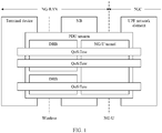
- a 5G QoS model based on a QoS flow (flow) is proposed, and is shown in FIG. 1 .
- the 5G QoS model supports a guaranteed bit rate QoS flow (namely, a GBR QoS flow) and a non-guaranteed bit rate QoS flow (namely, a non-GBR (non-GBR) QoS flow).
- Same transmission processing (such as scheduling or an admission threshold) is performed on data packets controlled by a same QoS flow.
- a terminal device may establish one or more PDU sessions with a 5G network.
- One or more QoS flows can be established in each PDU session.
- Each QoS flow is identified by a QoS flow identifier (QoS flow identifier, QFI), and the QFI uniquely identifies a QoS flow in a session.
- QFI QoS flow identifier
- each QoS flow corresponds to one data radio bearer (data radio bearer, DRB), and one DRB may correspond to one or more QoS flows.
- Whether a QoS flow is a GBR QoS flow or a non-GBR QoS flow is determined based on a corresponding QoS profile (QoS profile).
- a QoS profile corresponding to the GBR QoS flow needs to include the following QoS parameters: a 5QI, an ARP, a GFBR, and an MFBR, and optionally, includes QNC.
- the GBR QoS flows include a GRB QoS flow that requires notification control and a GBR QoS flow that does not require notification control.
- the access network device detects that a corresponding QoS flow resource cannot be met, the access network device notifies a session management function (session management function, SMF) network element of the event. Further, the SMF network element may initiate a QoS flow deletion or modification procedure.
- SMF session management function
- a QoS file corresponding to the non-GBR QoS flow needs to include the following QoS parameters: a 5QI and an ARP, and optionally, includes an RQA.
- the GBR QoS flow is mainly controlled in a signaling-based manner.
- a corresponding QoS flow establishment procedure is shown in FIG. 2 , and includes the following steps:
- the UPF network element For downlink, when receiving a downlink data packet, the UPF network element uses a data packet header of the downlink data packet to carry a QFI based on the SDF information sent by the SMF network element.
- the access network device places the downlink data packet on a corresponding DRB for transmission based on the QFI in the data packet header and the corresponding binding relationship between the QoS flow and the DRB.
- the terminal device determines a QoS flow according to a QoS rule, uses a data packet header of the to-be-sent uplink data packet to carry a QFI, and places the uplink data packet on a corresponding DRB for transmission based on the binding relationship between the QoS flow and the DRB.
- the access network device uses a data packet header of an uplink data packet between the access network device and the UPF network element to carry a QFI based on the QFI in the data packet header.
- the UPF network element verifies whether the data packet is transmitted through a correct QoS flow.
- the priority level, the averaging window, or the maximum data burst volume may alternatively be a parameter in a QoS attribute corresponding to the 5QI. This is not specifically limited herein.
- the multi-level PCC rule is introduced.
- a radio access network (radio access network, RAN) device or an SMF network element independently upgrades or degrades QoS based on a network status (for example, congestion).
- the multi-level PCC rule includes, e.g.:
- the SMF network element may generate, based on the multi-level PCC rule, a "special" QoS flow with a plurality of QoS profiles.
- a "special" QoS flow with a plurality of QoS profiles.
- the new type of QoS flow includes, e.g.:
- the multi-level PCC rule in the embodiments of this application is a PCC rule (PCC rule with alternative QoS parameter sets) with an alternative parameter group. Unified descriptions are provided herein. Details are not described below.
- a, b, or c may indicate: a, b, c, a and b, a and c, b and c, or a, b, and c, where a, b, and c may be singular or plural.
- terms such as “first”, “second”, and the like are used to distinguish between same objects or similar objects whose functions and purposes are basically the same. A person skilled in the art may understand that the terms such as “first” and “second” do not limit a quantity or an execution sequence, and the terms such as “first” and “second” do not indicate a definite difference.
- a word such as “example” or “for example” is used to represent giving an example, an illustration, or a description. Any embodiment or design scheme described as the word “example” or “for example” in the embodiments of this application should not be explained as being more preferred or having more advantages than another embodiment or design scheme. Exactly, use of the word “example”, “for example”, or the like is intended to present a relative concept in a specific manner for ease of understanding.
- a network architecture and a service scenario that are described in the embodiments of this application are intended to describe the technical solutions in the embodiments of this application more clearly, and do not constitute a limitation on the technical solutions provided in the embodiments of this application.
- a person of ordinary skill in the art may learn that with evolution of the network architecture and emergence of a new service scenario, the technical solutions provided in the embodiments of this application are also applicable to similar technical problems.
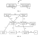
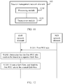
- FIG. 3 shows a communications system 30 according to an embodiment of this application.
- the communications system 30 includes a session management network element 301 and a policy control network element 302.
- the policy control network element 302 sends a first PCC rule to the session management network element 301.
- the session management network element 301 receives the first PCC rule from the policy control network element 302.
- the first PCC rule includes a binding parameter, and a binding parameter at leach level in the binding parameter corresponds to one rank value.
- the session management network element 302 determines, from a PCC rule bound to an existing QoS flow, whether there is a PCC rule in which a binding parameter corresponding to each of all rank values is the same as a binding parameter that is in the first PCC rule and that corresponds to a same rank value in all rank values.
- the session management network element 301 binds the first PCC rule to the existing QoS flow; or if there is no such PCC rule, the session management network element 301 creates a QoS flow according to the first PCC rule, and binds the first PCC rule to the created QoS flow.
- a specific implementation of the solution is described in detail in a subsequent method embodiment. Details are not described herein. Based on this solution, in this embodiment of this application, only the PCC rule in which the binding parameter corresponding to each of all the rank values is the same as the binding parameter corresponding to the same rank value in all the rank values in the first PCC rule can be bound to a same QoS flow.
- the policy control network element 302 sends a first PCC rule to the session management network element 301.
- the session management network element 301 receives the first PCC rule from the policy control network element 302.
- the session management network element 301 determines, from a PCC rule bound to an existing QoS flow, whether there is a PCC rule in which binding parameters at each level are the same as binding parameters at each level in the first PCC rule respectively. If there is the PCC rule, the session management network element 301 binds the first PCC rule to the existing QoS flow; or if there is no such PCC rule, the session management network element 301 creates a QoS flow according to the first PCC rule, and binds the first PCC rule to the created QoS flow.
- the policy control network element 302 sends a first PCC rule to the session management network element 301.
- the session management network element 301 receives the first PCC rule from the policy control network element 302.
- the session management network element 301 creates a QoS flow according to the first PCC rule, and binds the first PCC rule to the created QoS flow, where the QoS flow is bound to only the first PCC rule.
- a specific implementation of the solution is described in detail in a subsequent method embodiment. Details are not described herein. Based on this solution, in this embodiment of this application, each multi-level PCC rule is bound to a different QoS flow.
- the policy control network element 302 sends the first PCC rule to the session management network element 301.
- the session management network element 301 receives the first PCC rule from the policy control network element 302.
- the session management network element 301 determines that the first PCC rule needs to be bound to a separate QoS flow.
- the session management network element 301 creates a QoS flow according to the first PCC rule, and binds the first PCC rule to the created QoS flow.
- a specific implementation of the solution is described in detail in a subsequent method embodiment. Details are not described herein. Based on this solution, in this embodiment of this application, each multi-level PCC rule is bound to a different QoS flow.
- the policy control network element 302 is configured to send a first PCC rule to the session management network element 301, where the first PCC rule includes a binding parameter.
- the session management network element 301 is configured to: receive the first PCC rule from the policy control network element 302, and determine, from an existing QoS flow, whether there is a QoS flow for which a binding parameter is the same as the binding parameter in the first PCC rule.
- the session management network element 301 is further configured to: if the session management network element 301 determines that there is the QoS flow, bind the first PCC rule to the existing QoS flow; or if the session management network element 301 determines that there is no such QoS flow, create a QoS flow according to the first PCC rule, and bind the first PCC rule to the created QoS flow.
- only a PCC rule for which a binding parameter is the same as the binding parameter in the first PCC rule can be bound to a same QoS flow. This avoids a problem that a multi-level PCC rule and a single-level PCC rule that have a same binding parameter are bound to a same QoS flow, thereby further avoiding incorrect scheduling by a RAN device.
- the policy control network element 302 is configured to send a first PCC rule to the session management network element 301, where the first PCC rule includes a first binding parameter.
- the session management network element 301 is configured to receive the first PCC rule from the policy control network element 302.
- the session management network element 301 is further configured to: when determining that the first PCC rule includes an alternative quality of service QoS parameter set (alternative QoS parameter sets); and in a PCC rule bound to an existing first QoS flow, there is a second PCC rule in which a value of the first binding parameter is the same as a value of the first binding parameter included in the first PCC rule, and the second PCC rule includes an alternative QoS parameter set, bind the first PCC rule to the existing first QoS flow.
- alternative QoS parameter set alternative QoS parameter sets
- the session management network element 301 is further configured to: when determining that the first PCC rule does not include an alternative QoS parameter set; and in a PCC rule bound to an existing second QoS flow, there is a third PCC rule in which a value of the first binding parameter is the same as a value of the first binding parameter included in the first PCC rule, and the third PCC rule does not include an alternative QoS parameter set, bind the first PCC rule to the existing second QoS flow.
- one or more PCC rules that include alternative QoS parameter sets may be considered as PCC rules having a same binding parameter, and one or more PCC rules that do not include alternative QoS parameter sets may be considered as PCC rules having a same binding parameter.
- the one or more PCC rules having the same binding parameter can be bound to a same QoS flow, and the one or more PCC rules having the different binding parameters cannot be bound to a same QoS flow. This avoids a problem that a multi-level PCC rule and a single-level PCC rule that have a same binding parameter are bound to a same QoS flow, thereby further avoiding incorrect scheduling by a RAN device.
- the communications system 30 shown in FIG. 3 may be applied to a 5th generation (5th generation, 5G) network currently discussed, another future network, or the like. This is not specifically limited in this embodiment of this application.
- 5G 5th generation
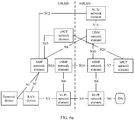
- a network element or an entity corresponding to the session management network element 301 may be an SMF network element in the non-roaming 5G network architecture
- a network element or an entity corresponding to the policy control network element 302 may be a PCF network element in the non-roaming 5G network architecture.
- the non-roaming 5G network architecture may further include a RAN device, a UPF network element, an AMF network element, a unified data management (unified data management, UDM) network element, an authentication server function (authentication server function, AUSF) network element, or the like. This is not specifically limited in this embodiment of this application.
- a terminal device communicates with the AMF network element through a next generation (next generation, N) 1 interface (N1 for short).
- the RAN device communicates with the AMF network element through an N2 interface (N2 for short), and the RAN device communicates with the UPF network element through an N3 interface (N3 for short).
- the UPF network element communicates with a DN through an N6 interface (N6 for short).
- the AMF network element communicates with the SMF network element through an N11 interface (N11 for short), the AMF network element communicates with the UDM network element through an N8 interface (N8 for short), the AMF network element communicates with the AUSF network element through an N12 interface (N12 for short), and the AMF network element communicates with the PCF network element through an N15 interface (N15 for short).
- the SMF network element communicates with the PCF network element through an N7 interface (N7 for short), the SMF network element communicates with the UPF network element through an N4 interface (N4 for short), and the SMF network element communicates with the UDM network element through an N10 interface (N10 for short).
- the UDM network element communicates with the AUSF network element through an N13 interface (N13 for short).
- control plane network elements such as the AMF network element, the SMF network element, the UDM network element, the AUSF network element, and the PCF network element in the non-roaming 5G network architecture shown in FIG. 4a may alternatively interact with each other through a service-oriented interface. For example, as shown in FIG.
- an external service-oriented interface provided by the AMF network element may be an Namf interface
- an external service-oriented interface provided by the SMF network element may be an Nsmf interface
- an external service-oriented interface provided by the UDM network element may be an Nudm interface
- an external service-oriented interface provided by the PCF network element may be an Npcf interface
- an external service-oriented interface provided by the AUSF network element may be an Nausf interface.
- 5G system architecture 5G system architecture
- a network element or an entity corresponding to the session management network element 301 may be an SMF network element in the local breakout roaming 5G network architecture, and a network element or an entity corresponding to the policy control network element 302 may be a visited PCF (visited PCF, vPCF) network element in the local breakout roaming 5G network architecture.
- a visited PCF visited PCF, vPCF
- the local breakout roaming 5G network architecture may further include a RAN device, a UPF network element, an AMF network element, a UDM network element, a home PCF (home PCF, hPCF) network element, an AUSF network element, or the like.
- a RAN device a UPF network element, an AMF network element, a UDM network element, a home PCF (home PCF, hPCF) network element, an AUSF network element, or the like.
- the UDM network element, the AUSF network element, and the hPCF network element belong to a home public land mobile network (home public land mobile network, HPLMN).
- the RAN device, the AMF network element, the SMF network element, the UPF network element, or the vPCF network element belongs to a visited public land mobile network (visited public land mobile network, VPLMN).
- a terminal device communicates with the AMF network element through an N1 interface (N1 for short).
- the RAN device communicates with the AMF network element through an N2 interface (N2 for short), and the RAN device communicates with the UPF network element through an N3 interface (N3 for short).
- the UPF network element communicates with a DN through an N6 interface (N6 for short).
- the AMF network element communicates with the SMF network element through an N11 interface (N11 for short), the AMF network element communicates with the UDM network element through an N8 interface (N8 for short), the AMF network element communicates with the AUSF network element through an N12 interface (N12 for short), and the AMF network element communicates with the vPCF network element through an N15 interface (N15 for short).
- the SMF network element communicates with the vPCF network element through an N7 interface (N7 for short).
- the vPCF network element communicates with the hPCF network element through an N24 interface (N24 for short).
- the SMF network element communicates with the UPF network element through an N4 interface (N4 for short), and the SMF network element communicates with the UDM network element through an N10 interface (N10 for short).
- the UDM network element communicates with the AUSF network element through an N13 interface (N13 for short).
- control plane network elements such as the AMF network element, the SMF network element, the UDM network element, the AUSF network element, the vPCF network element, and the hPCF network element in the local breakout roaming 5G network architecture shown in FIG. 5a may alternatively interact with each other through a service-oriented interface. For example, as shown in FIG.
- an external service-oriented interface provided by the AMF network element may be an Namf interface
- an external service-oriented interface provided by the SMF network element may be an Nsmf interface
- an external service-oriented interface provided by the UDM network element may be an Nudm interface
- an external service-oriented interface provided by the vPCF network element may be an Npcf interface
- an external service-oriented interface provided by the hPCF network element may be an Npcf interface
- an external service-oriented interface provided by the AUSF network element may be an Nausf interface.
- a visited security edge protection agent (visited security edge protection proxy, vSEPP) in FIG.
- a home security edge protection proxy (home security edge protection proxy, hSEPP) in FIG. 5b is configured to perform information filtering, policy control, topology hiding, and the like on a control plane interface in the HPLMN.
- the vSEPP is connected to the hSEPP through an N32 interface (N32 for short).
- N32 for short.
- a network element or an entity corresponding to the session management network element 301 may be a home SMF (home SMF, hSMF) network element in the home routed roaming 5G network architecture, and a network element or an entity corresponding to the policy control network element 302 may be an hPCF network element in the home routed roaming 5G network architecture.
- a network element or an entity corresponding to the session management network element 301 may be a home SMF (home SMF, hSMF) network element in the home routed roaming 5G network architecture
- a network element or an entity corresponding to the policy control network element 302 may be an hPCF network element in the home routed roaming 5G network architecture.
- the home routed roaming 5G network architecture may further include a RAN device, a home UPF (home UPF, hUPF) network element, a visited UPF (visited UPF, vUPF) network element, a visited SMF (visited SMF, vSMF) network element, an AMF network element, a UDM network element, a vPCF network element, an AUSF network element, or the like.
- a RAN device a home UPF (home UPF, hUPF) network element, a visited UPF (visited UPF, vUPF) network element, a visited SMF (visited SMF, vSMF) network element, an AMF network element, a UDM network element, a vPCF network element, an AUSF network element, or the like.
- the UDM network element, the AUSF network element, the hSMF network element, the hPCF network element, or the hUPF network element belongs to an HPLMN.
- a terminal device communicates with the AMF network element through an N1 interface (N1 for short).
- the RAN device communicates with the AMF network element through an N2 interface (N2 for short), and the RAN device communicates with the vUPF network element through an N3 interface (N3 for short).
- the vUPF network element communicates with the hUPF network element through an N9 interface (N9 for short).
- the hUPF network element communicates with a DN through an N6 interface (N6 for short).
- the AMF network element communicates with the vSMF network element through an N11 interface (N11 for short).
- the vSMF network element communicates with the hSMF network element through an N16 interface (N16 for short).
- the AMF network element communicates with the UDM network element through an N8 interface (N8 for short), the AMF network element communicates with the AUSF network element through an N12 interface (N12 for short), and the AMF network element communicates with the vPCF network element through an N15 interface (N15 for short).
- the vPCF network element communicates with the hPCF network element through an N24 interface (N24 for short).
- the vSMF network element communicates with the vUPF network element through an N4 interface (N4 for short).
- the hSMF network element communicates with the hUPF network element through an N4 interface (N4 for short), the hSMF network element communicates with the UDM network element through an N10 interface (N10 for short), and the hSMF network element communicates with the hPCF network element through an N7 interface (N7 for short).
- the UDM network element communicates with the AUSF network element through an N13 interface (N13 for short).
- control plane network elements such as the AMF network element, the vSMF network element, the hSMF network element, the UDM network element, the AUSF network element, the vPCF network element, and the hPCF network element in the home routed roaming 5G network architecture shown in FIG. 6a may alternatively interact with each other through a service-oriented interface. For example, as shown in FIG.
- an external service-oriented interface provided by the AMF network element may be an Namf interface
- an external service-oriented interface provided by the vSMF network element may be an Nvsmf interface
- an external service-oriented interface provided by the hSMF network element may be an Nhsmf interface
- an external service-oriented interface provided by the UDM network element may be an Nudm interface
- an external service-oriented interface provided by the vPCF network element may be an Nvpcf interface
- an external service-oriented interface provided by the hPCF network element may be an Nhpcf interface
- an external service-oriented interface provided by the AUSF network element may be an Nausf interface.
- FIG. 6b is configured to perform information filtering, policy control, topology hiding, and the like on a control plane interface in the VPLMN.
- An hSEPP in FIG. 6b is configured to perform information filtering, policy control, topology hiding, and the like on a control plane interface in the HPLMN.
- the vSEPP is connected to the hSEPP through an N32 interface (N32 for short).
- N32 for short.
- 5G system architecture 5G system architecture
- the terminal device in this embodiment of this application may be a device such as a terminal or a chip that may be used in a terminal, configured to implement a wireless communication function.
- the terminal may be user equipment (user equipment, UE), an access terminal, a terminal unit, a terminal station, a mobile station, a mobile console, a remote station, a remote terminal, a mobile device, a wireless communications device, a terminal agent, a terminal apparatus, or the like in a 5G network or a future evolved PLMN.
- the access terminal may be a cellular phone, a cordless phone, a session initiation protocol (session initiation protocol, SIP) phone, a wireless local loop (wireless local loop, WLL) station, a personal digital assistant (personal digital assistant, PDA), a handheld device having a wireless communication function, a computing device, another processing device connected to a wireless modem, a vehicle-mounted device, a wearable device, a virtual reality (virtual reality, VR) terminal device, an augmented reality (augmented reality, AR) terminal device, a wireless terminal in industrial control (industrial control), a wireless terminal in self driving (self driving), a wireless terminal in remote medical (remote medical), a wireless terminal in a smart grid (smart grid), a wireless terminal in transportation safety (transportation safety), a wireless terminal in a smart city (smart city), a wireless terminal in a smart home (smart home), or the like.
- the terminal may be mobile or in a fixed position.
- the RAN device in this embodiment of this application is a device that accesses a core network, for example, may be a base station, a broadband network gateway (broadband network gateway, BNG), an aggregation switch, or a non-3rd generation partnership project (3rd generation partnership project, 3GPP) access device.
- the base station may include base stations in various forms, for example, a macro base station, a micro base station (also referred to as a small cell), a relay station, and an access point.
- the session management network element in this embodiment of this application may also be referred to as a communications apparatus, and may be a general-purpose device or a dedicated device. This is not specifically limited in this embodiment of this application.
- a related function of the session management network element in this embodiment of this application may be implemented by one device, or may be jointly implemented by a plurality of devices, or may be implemented by one or more function modules in one device.
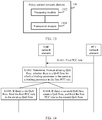
- FIG. 7 is a schematic structural diagram of a communications device 700 according to an embodiment of this application.
- the communications device 700 includes one or more processors 701, a communications line 702, and at least one communications interface (only an example in which the communications device 700 includes a communications interface 704 and one processor 701 is used in FIG. 7 for description).
- the communications device 700 may further include a memory 703.
- the processor 701 may be a general-purpose central processing unit (central processing unit, CPU), a microprocessor, an application-specific integrated circuit (application-specific integrated circuit, ASIC), or one or more integrated circuits configured to control program execution in the solutions of this application.
- CPU central processing unit
- ASIC application-specific integrated circuit
- the communications line 702 may include a path, to connect different components.
- the communications interface 704 may be a transceiver module configured to communicate with another device or a communications network, for example, the Ethernet, a RAN, or a wireless local area network (wireless local area networks, WLAN).
- the transceiver module may be an apparatus such as a transceiver or a transceiver.
- the communications interface 704 may alternatively be a transceiver circuit located inside the processor 701, and is configured to implement signal input and signal output of the processor.
- the memory 703 may be an apparatus having a storage function.
- the memory 703 may be a read-only memory (read-only memory, ROM) or another type of static storage device that can store static information and an instruction, or a random access memory (random access memory, RAM) or another type of dynamic storage device that can store information and an instruction.
- ROM read-only memory
- RAM random access memory
- the memory 703 may alternatively be an electrically erasable programmable read-only memory (electrically erasable programmable read-only memory, EEPROM), a compact disc read-only memory (compact disc read-only memory, CD-ROM) or another compact disc storage, an optical disc storage (including a compact disc, a laser disc, an optical disc, a digital versatile disc, a Blu-ray disc, or the like), a magnetic disk storage medium or another magnetic storage device, or any other medium that can be used to carry or store expected program code in a form of an instruction or a data structure and that is accessible by a computer.
- the memory 703 is not limited thereto.
- the memory may exist independently and is connected to the processor through the communications line 702.
- the memory may alternatively be integrated into the processor.
- the memory 703 is configured to store a computer execution instruction for executing the solutions of this application, and the processor 701 controls the execution.
- the processor 701 is configured to execute the computer execution instruction stored in the memory 703, to implement a charging rule binding method provided in the following embodiments of this application.
- the processor 701 may perform processing related functions in a charging rule binding method provided in the following embodiments of this application, and the communications interface 704 is responsible for communicating with another device or a communications network. This is not specifically limited in this embodiment of this application.
- the computer execution instruction in this embodiment of this application may also be referred to as application program code. This is not specifically limited in this embodiment of this application.
- the processor 701 may include one or more CPUs, for example, a CPU 0 and a CPU 1 in FIG. 7 .
- the communications device 700 may include a plurality of processors, for example, the processor 701 and a processor 708 in FIG. 7 .
- Each of the processors may be a single-core processor (single-CPU) or a multi-core processor (multi-CPU).
- the processor herein may be one or more devices, circuits, and/or processing cores configured to process data (for example, a computer program instruction).
- the communications device 700 may further include an output device 705 and an input device 706.
- the output device 705 communicates with the processor 701, and may display information in a plurality of manners.
- the output device 705 may be a liquid crystal display (liquid crystal display, LCD), a light emitting diode (light emitting diode, LED) display device, a cathode ray tube (cathode ray tube, CRT) display device, or a projector (projector).
- the input device 706 communicates with the processor 701, and may receive an input of a user in a plurality of manners.
- the input device 706 may be a mouse, a keyboard, a touchscreen device, or a sensing device.
- the communications device 700 may also be referred to as a communications apparatus sometimes, and may be a general-purpose device or a dedicated device.
- the communications device 700 may be a desktop computer, a portable computer, a network server, a personal digital assistant (personal digital assistant, PDA), a mobile phone, a tablet computer, a wireless terminal device, an embedded device, the foregoing terminal device, the foregoing network device, or a device having a structure similar to the structure shown in FIG. 7 .
- a type of the communications device 700 is not limited in this embodiment of this application.
- names of messages between network elements are merely examples, and there may be other names in a specific implementation. This is not specifically limited in this embodiment of this application.
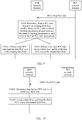
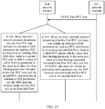
- FIG. 8 shows a charging rule binding method according to an embodiment of this application.
- the charging rule binding method includes the following steps.
- a PCF network element sends a first PCC rule to an SMF network element.
- the SMF network element receives the first PCC rule from the PCF network element.
- the first PCC rule includes a binding parameter, and a binding parameter at leach level in the binding parameter corresponds to one rank value.
- the first PCC rule in this embodiment of this application may be a single-level PCC rule or a multi-level PCC rule. This is not specifically limited in this embodiment of this application.
- the multi-level PCC rule refer to the foregoing part of the specific implementation. Details are not described herein again.
- a binding parameter at leach level in the binding parameter corresponds to one rank value includes: a binding parameter at leach level in the binding parameter includes the one rank value.
- a binding parameter at each level includes a rank value, a 5QI, and an ARP.
- the PCC rule includes one or more of the following parameters, the one or more of the following parameters may also be used as the binding parameter: QNC, a priority level, an averaging window, or an MDBV.
- the priority level, the averaging window, or the MDBV may alternatively be a parameter in a QoS attribute corresponding to the 5QI. This is not specifically limited herein.
- the first PCC rule may include:
- a value of the binding parameter may include:
- a binding parameter at leach level in the binding parameter corresponds to one rank value includes: the first PCC rule further includes the rank value corresponding to a binding parameter at leach level in the binding parameter.
- the first PCC rule may include:
- a rank value and a value of a corresponding binding parameter may include:
- the single-level PCC rule may alternatively not include the rank value. This is not specifically limited in this embodiment of this application.
- the SMF network element determines, from a PCC rule bound to an existing QoS flow, whether there is a PCC rule in which a binding parameter corresponding to each of all rank values is the same as a binding parameter corresponding to a same rank value in all rank values in the first PCC rule.
- the first PCC rule (namely, a PCC rule 1) may include:
- a value of the binding parameter may include:
- a PCC rule bound to an existing QoS flow 1 includes a PCC rule 2, and the PCC rule 2 may include:
- a value of the binding parameter may include:
- a PCC rule bound to an existing QoS flow 3 includes a PCC rule 4, and the PCC rule 4 may include:
- a value of the binding parameter may include:
- the PCC rule 2 bound to the existing QoS flow 1, although the binding parameter corresponding to rank 1 is the same as the binding parameter corresponding to rank 1 in the PCC rule 1, and the binding parameter corresponding to rank 2 is the same as the binding parameter corresponding to rank 2 in the PCC rule 1, the PCC rule 2 further includes the binding parameter corresponding to rank 3. Therefore, a binding parameter corresponding to each of all rank values in the PCC rule 2 is different from a binding parameter corresponding to a same rank value in all rank values in the PCC rule 1.
- the binding parameter corresponding to rank 1 is the same as the binding parameter corresponding to rank 1 in the PCC rule 1 in the PCC rule 1
- the PCC rule 1 further includes the binding parameter corresponding to rank 2. Therefore, a binding parameter corresponding to each of all rank values in the PCC rule 2 is different from a binding parameter corresponding to a same rank value in all rank values in the PCC rule 1.
- the binding parameter corresponding to rank 1 is the same as the binding parameter corresponding to rank 1 in the PCC rule 1
- the binding parameter corresponding to rank 2 is the same as the binding parameter corresponding to rank 2 in the PCC rule 1. Therefore, a binding parameter corresponding to each of all rank values in the PCC rule 2 is the same as a binding parameter corresponding to a same rank value in all rank values in the PCC rule 1.
- one QoS flow is bound to one PCC rule.
- one QoS flow may be bound to one or more PCC rules. Binding parameters corresponding to all of a plurality of PCC rules are the same.
- a binding parameter corresponding to a rank is the same as or different from a binding parameter corresponding to a same rank in the first PCC rule may also be understood as that in a parameter of the existing QoS flow, a binding parameter corresponding to a rank is the same as or different from a binding parameter corresponding to a same rank in the first PCC rule.
- the binding parameter corresponding to rank 1 is the same as the binding parameter corresponding to rank 1 in the PCC rule 1 may also be understood as that in a parameter of the existing QoS flow 1, a binding parameter corresponding to rank 1 is the same as a binding parameter corresponding to rank 1 in the PCC rule 1.
- the description is further applicable to the embodiment shown in FIG. 9 . Unified descriptions are provided herein. Details are not described below.
- the SMF network element determines that there is the PCC rule in which the binding parameter corresponding to each of all the rank values is the same as the binding parameter that is in the first PCC rule and that corresponds to the same rank value in all the rank values.
- the SMF network element performs step S803.
- the SMF network element determines that there is no such PCC rule in which the binding parameter corresponding to each of all the rank values is the same as the binding parameter that is in the first PCC rule and that corresponds to the same rank value in all the rank values.
- the SMF network element may bind the first PCC rule to the QoS flow 3.
- the first PCC rule to the QoS flow 3 refer to an existing binding mechanism. Details are not described herein.
- S804 If there is no such PCC rule, the SMF network element creates a QoS flow according to the first PCC rule, and binds the first PCC rule to the created QoS flow.
- the SMF network element creates the QoS flow according to the first PCC rule, and binds the first PCC rule to the created QoS flow.
- binding the first PCC rule to the created QoS flow refer to an existing binding mechanism. Details are not described herein.
- the QoS flow created according to the first PCC rule may include:
- the actions of the SMF network element in steps S801 to S803 or step S804 may be performed by the processor 701 in the communications device 700 shown in FIG. 7 by invoking the application program code stored in the memory 703. This is not limited in this embodiment.
- FIG. 9 shows a charging rule binding method according to an embodiment of this application.
- the charging rule binding method includes the following steps.
- a PCF network element sends a first PCC rule to an SMF network element.
- the SMF network element receives the first PCC rule from the PCF network element.
- the first PCC rule in this embodiment of this application may be a single-level PCC rule or a multi-level PCC rule. This is not specifically limited in this embodiment of this application.
- a form of the first PCC rule may be the same as the form of the first PCC rule shown in step S801, or may be different from the form of the first PCC rule shown in step S801. This is not specifically limited herein.
- the SMF network element determines, from a PCC rule bound to an existing QoS flow, whether there is a PCC rule in which binding parameters at each level are the same as binding parameters at each level in the first PCC rule respectively.
- the SMF network element determines, from a PCC rule bound to an existing QoS flow, whether there is a PCC rule in which binding parameters at each level are the same as binding parameters at each level in the first PCC rule respectively includes: The SMF network element determines, from the PCC rule bound to the existing QoS flow, whether there is a PCC rule for which a corresponding maximum rank value is the same as a maximum rank value corresponding to the first PCC rule.
- the SMF network element determines, from the PCC rule bound to the existing QoS flow, that there is the PCC rule in which the binding parameters at each level are the same as the binding parameters at each level in the first PCC rule respectively; or if there is no such PCC rule for which a corresponding maximum rank value is the same as the maximum rank value corresponding to the first PCC rule, the SMF network element determines, from the PCC rule bound to the existing QoS flow, that there is no such PCC rule in which the binding parameters at each level are the same as the binding parameters at each level in the first PCC rule respectively.
- the first PCC rule (namely, a PCC rule 1) may include:
- a value of the binding parameter may include:
- a PCC rule bound to an existing QoS flow 1 includes a PCC rule 2, and the PCC rule 2 may include:
- a value of the binding parameter may include:
- a PCC rule bound to an existing QoS flow 3 includes a PCC rule 4, and the PCC rule 4 may include:
- a value of the binding parameter may include:
- a PCC rule bound to an existing QoS flow 4 includes a PCC rule 5, and the PCC rule 5 may include:
- a value of the binding parameter may include:
- maximum rank values corresponding to the PCC rule 4 bound to the existing QoS flow 3 and the PCC rule 5 bound to the existing QoS flow 4 are the same as a maximum rank value corresponding to the first PCC rule (namely, the PCC rule 1), and are both rank 2.
- a binding parameter at each level in the PCC rule 5 includes the MDBV, but a binding parameter at each level in the first PCC rule does not include the MDBV, a binding parameter at each level in the PCC rule 5 is different from a binding parameter at each level in the first PCC rule, but binding parameters at each level in the PCC rule 4 are the same as binding parameters at each level in the first PCC rule respectively.
- the SMF network element may alternatively perform detection in sequence until a quantity of times reaches a maximum rank value. This is not specifically limited in this embodiment of this application.
- the SMF network element determines that there is the PCC rule in which the binding parameters are the same as the binding parameters at each level in the first PCC rule respectively. Alternatively, if the SMF network element determines that there is no such PCC rule in which the binding parameters at each level are the same as the binding parameters at each level in the first PCC rule respectively, the SMF network element performs step S904.
- the SMF network element may bind the first PCC rule to the QoS flow 3.
- the first PCC rule to the QoS flow 3 refer to an existing binding mechanism. Details are not described herein.
- S904 If there is no such PCC rule, the SMF network element creates a QoS flow according to the first PCC rule, and binds the first PCC rule to the created QoS flow.
- the SMF network element creates the QoS flow according to the first PCC rule, and binds the first PCC rule to the created QoS flow.
- binding the first PCC rule to the created QoS flow refer to an existing binding mechanism. Details are not described herein.
- the QoS flow created according to the first PCC rule may include:
- the actions of the SMF network element in steps S901 to S903 or step S904 may be performed by the processor 701 in the communications device 700 shown in FIG. 7 by invoking the application program code stored in the memory 703. This is not limited in this embodiment.
- FIG. 10 shows a charging rule binding method according to an embodiment of this application.
- the charging rule binding method includes the following steps.
- a PCF network element sends a first PCC rule to an SMF network element.
- the SMF network element receives the first PCC rule from the PCF network element.
- a form of the first PCC rule may be the same as the form of the first PCC rule shown in step S801, or may be different from the form of the first PCC rule shown in step S801. This is not specifically limited herein.
- the SMF network element determines that the first PCC rule is a multi-level PCC rule.
- the SMF network element may determine, by using an explicit or implicit indication, that the first PCC rule is the multi-level PCC rule.
- the first PCC rule in this embodiment of this application may include indication information, and the indication information is used to indicate that the first PCC rule is the multi-level PCC rule.
- the SMF network element determines that the first PCC rule is a multi-level PCC rule may include: The SMF network element determines, based on the indication information, that the first PCC rule is the multi-level PCC rule.
- the indication information may be a multi-level indication (multiple indication), and may be indicated by using a special flag bit.
- a 1-bit flag bit is set.
- a value of 0 indicates a single-level indication, and a value of 1 indicates a multi-level indication.
- a value of 1 indicates a single-level indication, and a value of 0 indicates a multi-level indication, or the like. This is not specifically limited herein.
- the first PCC rule in this embodiment of this application may include N alternative QoS parameter sets (Alternative QoS parameter set(s)), where N is a positive integer greater than 1.
- that the SMF network element determines that the first PCC rule is a multi-level PCC rule may include: The SMF network element determines, based on the N alternative QoS parameter sets, that the first PCC rule is the multi-level PCC rule.
- each alternative QoS parameter set may correspond to one rank value, and one rank value corresponds to one level of binding parameters. Unified descriptions are provided herein. Details are not described below.
- that the SMF network element determines, based on the N alternative QoS parameter sets, that the first PCC rule is the multi-level PCC rule may include: The SMF network element determines, based on N rank values corresponding to the N alternative QoS parameter sets, that the first PCC rule is the multi-level PCC rule.
- S1003 The SMF network element creates a QoS flow according to the first PCC rule, and binds the first PCC rule to the created QoS flow, where the QoS flow is bound to only the first PCC rule.
- any multi-level PCC rule sent by the PCF network element to the SMF network element is bound to a unique QoS flow, and no other PCC rule is bound to the QoS flow.
- step S804 For related descriptions that the SMF network element creates the QoS flow according to the first PCC rule, and binds the first PCC rule to the created QoS flow, refer to step S804 or step S904. Details are not described herein again.
- each multi-level PCC rule is bound to a different QoS flow. Therefore, a problem that a multi-level PCC rule and a single-level PCC rule that have a same binding parameter are bound to a same QoS flow, or multi-level PCC rules having a same binding parameter but different ranks are bound to a same QoS flow is avoided, thereby further avoiding incorrect scheduling by a RAN device.
- the actions of the SMF network element in steps S1001 to S1003 may be performed by the processor 701 in the communications device 700 shown in FIG. 7 by invoking the application program code stored in the memory 703. This is not limited in this embodiment.
- the first PCC rule in the embodiments shown in FIG. 8 to FIG. 10 may be a new PCC rule, or a PCC rule obtained by modifying the existing PCC rule. This is not specifically limited in this embodiment of this application.
- FIG. 12 shows another charging rule binding method according to an embodiment of this application.
- the charging rule binding method includes the following steps.
- a PCF network element sends a first PCC rule to an SMF network element.
- the SMF network element receives the first PCC rule from the PCF network element.
- a form of the first PCC rule may be the same as the form of the first PCC rule shown in step S801, or may be different from the form of the first PCC rule shown in step S801. This is not specifically limited herein.
- S1202 The SMF network element determines that the first PCC rule needs to be bound to a separate QoS flow.
- the SMF network element may determine, by using an explicit or implicit indication, that the first PCC rule needs to be bound to the separate QoS flow.
- the first PCC rule in this embodiment of this application may include indication information.
- that the SMF network element determines that the first PCC rule needs to be bound to a separate QoS flow may include: The SMF network element determines, based on the indication information, that the first PCC rule needs to be bound to the separate QoS flow.
- the indication information may be explicit indication information.
- the indication information is information indicating that the first PCC rule needs to be bound to the separate QoS flow.
- a name of the indication information may be "bind to separate QoS flow" (bind to independent QoS flow or bind to separate QoS flow), and the indication information may be used to indicate that the PCC rule needs to be bound to a separate QoS flow (indicates that the PCC rule shall be bound to an independent/separate QoS Flow). In this way, the SMF network element binds the PCC rule to the separate QoS flow provided that the indication information exists.
- the indication information may be implicit indication information.
- the indication information may be the multi-level indication (multiple indication) in the foregoing embodiment, and may be indicated by using a special flag bit. For example, a 1-bit flag bit is set. A value of 0 indicates a single-level indication, and a value of 1 indicates a multi-level indication. Alternatively, a value of 1 indicates a single-level indication, and a value of 0 indicates a multi-level indication, or the like. This is not specifically limited herein. In this way, the SMF network element may determine, based on the indication information, that the first PCC rule needs to be bound to the separate QoS flow.
- S1203 The SMF network element creates a QoS flow according to the first PCC rule, and binds the first PCC rule to the created QoS flow, where the QoS flow is bound to only the first PCC rule.
- any multi-level PCC rule sent by the PCF network element to the SMF network element is bound to a unique QoS flow, and no other PCC rule is bound to the QoS flow.
- the SMF network element may alternatively determine, by using a flag bit in the SMF network element, that a QoS flow is a separate QoS flow.
- another PCC rule cannot be bound to the QoS flow.
- a flag bit of the QoS flow is 1, and the another PCC rule cannot be bound to the QoS flow.
- the SMF network element records a QFI of the separate QoS flow, and the another PCC rule cannot be bound to the QoS flow.
- step S804 For related descriptions that the SMF network element creates the QoS flow according to the first PCC rule and binds the first PCC rule to the created QoS flow, refer to step S804 or step S904. Details are not described herein again.
- each multi-level PCC rule is bound to a different QoS flow. This avoids a problem that a multi-level PCC rule and a single-level PCC rule that have a same binding parameter are bound to a same QoS flow, or that multi-level PCC rules having a same binding parameter but different ranks are bound to a same QoS flow, thereby further avoiding incorrect scheduling by a RAN device.
- the actions of the SMF network element in steps S1201 to S1203 may be performed by the processor 701 in the communications device 700 shown in FIG. 7 by invoking the application program code stored in the memory 703. This is not limited in this embodiment.
- Multi-access (multi-access, MA) PDU session may include a GBR QoS flow or a non-GBR QoS flow.
- the SMF network element delivers QoS profiles (namely, 3GPP access and non-3GPP access) to AN devices on two sides.
- the GBR QoS flow if the GBR QoS flow allows only one access technology, the SMF network element sends a QoS profile to only an allowed AN device.
- the SMF network element determines a specific AN device to which a QoS profile is to be sent.
- the GBR QoS flow includes only one access technology at a time point.
- a service flow with a GBR requirement may be transmitted through a QoS flow that supports MA, but the service flow does not support MA transmission (for example, supports only 3GPP transmission).
- a service flow with a GBR requirement may be transmitted through a QoS flow that does not support MA (for example, supports only 3GPP transmission), but the service flow supports MA transmission.
- the SMF network element may choose to use an inappropriate access technology to transmit the GBR QoS flow.
- an allowed access mode for example, a steering mode
- this binding parameter (including a delay critical (delay critical) GBR and a normal GBR) may be introduced when a 5QI resource type in a PCC rule is a GBR.
- a new binding parameter is added each time a new feature is introduced, which causes complexity to a binding mechanism.
- the manner in the embodiment shown in FIG. 12 may also be used to resolve the problem.
- the indication information in FIG. 12 may be a multi-access indication (multiple access indication), and may be indicated by using a special flag bit. For example, a 2-bit flag bit is set.
- a value of 01 indicates a 3GPP single-access indication
- a value of 10 indicates a non-3GPP single-access indication
- a value of 11 indicates a multi-access indication.
- a value of 1 indicates a single-access indication
- a value of 0 indicates a multi-access indication, or the like. This is not specifically limited herein.
- a network side an SMF network element
- the SMF network element determines, based on an authorized 5QI, a capability of an NG-RAN, and a configuration of an operator, whether to perform redundant transmission.
- the 5QI includes a QoS characteristic packet error rate (packet error rate, PER), which reflects reliability required by a service.
- PER packet error rate
- 5G supports a dynamic 5QI.
- a parameter such as a PDB or a PER allocated by a network is delivered, or a same 5QI may have different QoS characteristics.
- service flows with a same 5QI may have different reliability requirements (reflected as having different PDRs)
- the SMF network element uniformly determines whether to perform redundant transmission on a QoS flow. Consequently, the SMF network element may select an inappropriate manner to transmit the service flow. For example, redundant transmission is determined to be performed on a service flow that does not require redundant transmission, and redundant transmission is determined not to be performed on a service flow that requires redundant transmission.
- the indication information in FIG. 12 may be a redundant indication (redundant indication), and may be indicated by using a special flag bit. For example, a 1-bit flag bit is set. A value of 0 indicates a redundant indication, and a value of 1 indicates a non-redundant indication.
- a value of 1 indicates a redundant indication
- a value of 0 indicates a non-redundant indication, or the like. This is not specifically limited herein.
- a network side or a RAN side may divide an end-to-end (end to end, E2E) PDB into two parts: a PDB of a UPF-RAN and a PDB of RAN-UE. In this way, the RAN may perform scheduling based on the PDB of the RAN-UE.
- E2E end to end
- the SMF network element After selecting a UPF network element, the SMF network element obtains the PDB of the UPF-RAN based on a configuration, and sends the PDB of the UPF-RAN to a RAN device in an N2 session management (session management, SM) message; and the RAN device obtains the PDB of the RAN-UE based on the E2E PDB included in a QoS profile and the PDB that is of the UPF-RAN and that is sent by the SMF network element.
- the SMF network element may manage a plurality of PDU session anchor (PDU session anchor, PSA) UPF network elements, different service flows in a same QoS flow may be transmitted by different PSA UPF network elements.
- PDU session anchor PDU session anchor
- a network side may need to provide a QoS monitoring service. To be specific, the network monitors whether QoS of these services can be currently satisfied by the network.
- the network side may perform monitoring at a granularity of a QoS flow.
- some service flows in a QoS flow may need to be reported, and some other service flows in the QoS flow do not need to be reported.
- the manner in the embodiment shown in FIG. 12 may also be used to resolve the problem.
- TSC assistance information TSC assistance information
- Flow direction Direction of a TSC flow (uplink or downlink) (The direction of the TSC flow (uplink or downlink)) Periodicity (periodicity) Time period between start moments of two data bursts (It refers to the time period between start of two bursts) Burst arrival time (burst arrival time) Arrival time of a data burst at either an ingress interface (downlink flow direction) of a RAN or an egress interface (uplink flow direction) of UE (The arrival time of the data burst at either the ingress of the RAN (downlink flow direction) or egress interface of the UE (uplink flow direction)) Burst size (burst size)
- a maximum data burst volume (Maximun Data Burst Volume) is set to a maximum burst size of aggregated TSC streams to be allocated to this QoS flow (For TSC QoS flows,
- the RAN device When performing QoS control, the RAN device performs QoS control at a granularity of a QoS flow.
- QoS flows are distinguished from each other by using parameters such as a 5QI and an ARP.
- parameters such as a 5QI and an ARP.
- different services in a QoS flow may have different flow directions, periodicities, burst arrival times, burst sizes, and the like, but the RAN device cannot distinguish between the services. Consequently, the RAN device may perform incorrect scheduling.
- a possible solution is to use all parameters in the TSCAI as binding parameters, or set indexes for all parameters. Each index represents a value determined for a parameter in the TSCAI, and the index is used as the binding parameter.
- a new binding parameter is added each time a new feature is introduced, which causes complexity to a binding mechanism.
- the manner in the embodiment shown in FIG. 12 may also be used to resolve the problem.
- a parameter namely, a delayed packet discarding (delayed packet discarding) identifier is introduced.
- the delayed packet discarding identifier indicates a RAN device to discard a data packet whose transmission delay exceeds a PDB in the QoS flow.
- the RAN device performs QoS control at a granularity of a QoS flow.
- QoS flows are distinguished from each other by using parameters such as a 5QI and an ARP.
- parameters such as a 5QI and an ARP.
- different services in a QoS flow may have different packet loss requirements, but the RAN device cannot distinguish between the services. Consequently, the RAN device may perform incorrect scheduling.
- a possible solution is to use a packet discarding identifier as a binding parameter.
- a new binding parameter is added each time a new feature is introduced, which causes complexity to a binding mechanism.
- the manner in the embodiment shown in FIG. 12 may also be used to resolve the problem.
- Other problems that need to be resolved by introducing a new binding parameter may be resolved in the manner in the embodiment shown in FIG. 12 . This is not specifically limited in this embodiment of this application.
- the PCF network element may determine, in one or more of the following conditions, to add the indication information in step S1202 to the first PCC rule:
- the first PCC rule is a multi-level PCC rule; a service corresponding to the first PCC rule supports multi-access; a service corresponding to the first PCC rule is a URLLC service (for example, a 5QI resource type is a delay critical GBR); a service corresponding to the first PCC rule requires redundant transmission (for example, a PER is less than a limit value); a data network access identifier (data network access identifier, DNAI) of the first PCC rule is different from a DNAI in another existing PCC rule (in a current PDU session); a PER in the first PCC rule is different from a PER in another existing PCC rule (in a current PDU session); a PDB of the first PCC rule is different from a PDB of another existing PCC rule (in
- an attribute of the PCC rule may also be referred to as an attribute of the service corresponding to the PCC rule, and vice versa.
- the service corresponding to the first PCC rule supports multi-access may also be referred to as that the first PCC rule supports multi-access.
- the indication information in step S1202 may alternatively be any one of the following:
- the PCF network element may alternatively determine, based on other information, whether to add the indication information in step S1202 to the first PCC rule, and content of the indication information may alternatively be other content. This is not specifically limited in this embodiment of this application.
- FIG. 8 to FIG. 10 are all described by using an example in which the communications system shown in FIG. 3 is applied to the 5G network architecture in the non-roaming scenario shown in FIG. 4a or FIG. 4b .
- the communications system shown in FIG. 3 is applied to the local breakout roaming 5G network architecture shown in FIG. 5a or FIG. 5b is used for description, or an example in which the communications system shown in FIG. 3 is applied to the home routed roaming 5G network architecture shown in FIG. 6a or FIG. 6b is used for description
- a corresponding charging rule binding method is similar to the method in the foregoing embodiment, and only a related network element needs to be adaptively replaced. Details are not described herein again.
- FIG. 14 shows a charging rule binding method according to an embodiment of this application.
- the charging rule binding method includes the following steps.
- a PCF network element sends a first PCC rule to an SMF network element.
- the SMF network element receives the first PCC rule from the PCF network element.
- the first PCC rule in this embodiment of this application may be a single-level PCC rule or a multi-level PCC rule. This is not specifically limited in this embodiment of this application.
- QoS parameters in the multi-level PCC rule include a policy control (policy control) part and an alternative QoS parameter set (alternative QoS parameter sets) part.
- the multi-level PCC rule includes two parts: a policy control (policy control) part and an alternative QoS parameter set (alternative QoS parameter sets) part.
- the policy control part is a QoS parameter that needs to be currently used.
- the alternative QoS parameter set part is a QoS parameter that may be used in the future based on a resource condition of a RAN device.
- a form of the first PCC rule may be the same as the form of the first PCC rule shown in step S801, or may be different from the form of the first PCC rule shown in step S801. This is not specifically limited herein.
- the SMF network element determines, from an existing QoS flow, whether there is a QoS flow for which a binding parameter is the same as a binding parameter in the first PCC rule.
- the binding parameter in the first PCC rule may include some parameters in an alternative QoS parameter set part, for example, a 5QI.
- the binding parameter in the first PCC rule may include all parameters in an alternative QoS parameter set part.
- all the parameters in the alternative QoS parameter set part may be used as the binding parameter in the first PCC rule. This is not specifically limited in this embodiment of this application.
- the first PCC rule (namely, a PCC rule 1) may include:
- a value of the binding parameter may include:
- a value of the binding parameter may include:
- the SMF network element determines, from an existing QoS flow, whether there is a QoS flow for which a binding parameter is the same as a binding parameter in the first PCC rule includes: If the SMF network element determines, from a PCC rule bound to the existing QoS flow, that there is a second PCC rule in which a value of a binding parameter of a policy control part is the same as a value of a binding parameter of a policy control part in the first PCC rule, and a value of a binding parameter of an alternative QoS parameter set part in the second PCC rule is the same as a value of a binding parameter of an alternative QoS parameter set part in the first PCC rule, the SMF network element determines, from the existing QoS flow, that there is the QoS flow for which the binding parameter is the same as the binding parameter in the first PCC rule; or if the SMF network element determines, from a PCC rule bound to the existing QoS flow, that there
- the QoS flow for which the binding parameter is the same as the binding parameter in the first PCC rule needs to meet the following: Binding parameters of the policy control part are the same, and binding parameters of the alternative QoS parameter set part are the same, but a sequence of the binding parameters of the alternative QoS parameter set part in the PCC rule may be different. Unified descriptions are provided herein. Details are not described below.
- a PCC rule bound to an existing QoS flow 1 includes a PCC rule 2
- the PCC rule 2 may include:
- a value of the binding parameter may include:
- a value of the binding parameter may include:
- PCC rule bound to an existing QoS flow 2 includes a PCC rule 3
- PCC rule 3 may include:
- a value of the binding parameter may include:
- a value of the binding parameter may include:
- the SMF network element may determine that the binding parameter of the existing QoS flow 1 is the same as the binding parameter in the first PCC rule, and the SMF network element may determine that the binding parameter of the existing QoS flow 2 is different from the binding parameter in the first PCC rule.
- the SMF network element determines that there is the QoS flow for which the binding parameter is the same as the binding parameter in the first PCC rule. Alternatively, if the SMF network element determines that there is no such QoS flow for which the binding parameter is the same as the binding parameter in the first PCC rule, the SMF network element performs step S1404.
- the SMF network element creates a QoS flow according to the first PCC rule, and binds the first PCC rule to the created QoS flow.
- the alternative QoS parameter set may also be directly used as the binding parameter.
- the alternative QoS parameter set may be used as an optional binding parameter.
- PCC rules include a PCC rule with an alternative QoS parameter set and a PCC rule without an alternative QoS parameter set.
- the PCC rule with an alternative QoS parameter set and the PCC rule without an alternative QoS parameter set cannot be bound to a same QoS flow.
- FIG. 15 shows a charging rule binding method according to an embodiment of this application.
- the charging rule binding method includes the following steps.
- step S1501 Same as step S1401 in the embodiment shown in FIG. 14 .
- step S1501 Same as step S1401 in the embodiment shown in FIG. 14 .
- step S1501 Same as step S1401 in the embodiment shown in FIG. 14 .
- step S1501 Same as step S1401 in the embodiment shown in FIG. 14 .
- step S1501 Same as step S1401 in the embodiment shown in FIG. 14 .
- step S1501 Same as step S1401 in the embodiment shown in FIG. 14 .
- FIG. 14 Details are not described herein again.
- S1502 When the SMF network element determines that the first PCC rule includes an alternative QoS parameter set; and in a PCC rule bound to an existing first QoS flow, there is a second PCC rule in which a value of a first binding parameter is the same as a value of a first binding parameter included in the first PCC rule, and the second PCC rule includes an alternative QoS parameter set, the SMF network element binds the first PCC rule to the first QoS flow.
- the first binding parameter in this embodiment of this application is a binding parameter other than the alternative QoS parameter set, for example, a 5QI, an ARP, QNC, a priority level, an averaging window, or an MDBV. This is not specifically limited in this embodiment of this application.
- S1503 When the SMF network element determines that the first PCC rule does not include an alternative QoS parameter set; and in a PCC rule bound to an existing second QoS flow, there is a third PCC rule in which a value of a first binding parameter is the same as a value of a first binding parameter included in the first PCC rule, and the third PCC rule does not include an alternative QoS parameter set, the SMF network element binds the first PCC rule to the second QoS flow.
- the SMF network element determines, from a PCC rule bound to an existing QoS flow, that there is no such PCC rule in which a value of a first binding parameter is the same as the value of the first binding parameter included in the first PCC rule, the SMF network element creates a QoS flow according to the first PCC rule, and binds the first PCC rule to the created QoS flow.
- binding the first PCC rule to the created QoS flow refer to an existing binding mechanism. Details are not described herein.
- one or more PCC rules that include alternative QoS parameter sets may be considered as PCC rules having a same binding parameter, and one or more PCC rules that do not include alternative QoS parameter sets may be considered as PCC rules having a same binding parameter.
- the one or more PCC rules having the same binding parameter can be bound to a same QoS flow, and the one or more PCC rules having the different binding parameters cannot be bound to a same QoS flow. In this way, a problem that a multi-level PCC rule and a single-level PCC rule that have a same binding parameter are bound to a same QoS flow is avoided, thereby further avoiding incorrect scheduling by a RAN device.
- methods and/or steps implemented by the session management network element may also be implemented by a component (for example, a chip or a circuit) that can be used in the session management network element
- methods and/or steps implemented by the policy control network element may also be implemented by a component (for example, a chip or a circuit) that can be used in the policy control network element.
- an embodiment of this application further provides a communications apparatus, and the communications apparatus is configured to implement the foregoing methods.
- the communications apparatus may be the session management network element in the foregoing method embodiments, or an apparatus including the session management network element, or a component that can be used in the session management network element.
- the communications apparatus may be the policy control network element in the foregoing method embodiments, or an apparatus including the policy control network element, or a component that can be used in the policy control network element. It can be understood that to implement the foregoing functions, the communications apparatus includes a corresponding hardware structure and/or software module for performing the functions.
- the communications apparatus may be divided into function modules based on the foregoing method embodiments.
- each function module may be obtained through division based on each corresponding function, or two or more functions may be integrated into one processing module.
- the integrated module may be implemented in a form of hardware, or may be implemented in a form of a software function module. It should be noted that in the embodiments of this application, division into the modules is an example and is merely logical function division, and may be other division in an actual implementation.
- FIG. 11 is a schematic structural diagram of a session management network element 110.
- the session management network element 110 includes a transceiver module 1101 and a processing module 1102.
- the transceiver module 1101 may also be referred to as a transceiver unit, and is configured to implement a transceiver function.
- the transceiver module 1101 may be a transceiver circuit, a transceiver, a transceiver, or a communications interface.
- the transceiver module 1101 is configured to receive a first PCC rule from a policy control network element, where the first PCC rule includes a binding parameter, and a binding parameter at leach level in the binding parameter corresponds to one rank value.
- the processing module 1102 is configured to determine, from a PCC rule bound to an existing QoS flow, whether there is a PCC rule in which a binding parameter corresponding to each of all rank values is the same as a binding parameter that is in the first PCC rule and that corresponds to a same rank value in all rank values.
- the processing module 1102 is further configured to: if there is the PCC rule, bind the first PCC rule to the existing QoS flow.
- the processing module 1102 is further configured to: if there is no such PCC rule, create a QoS flow according to the first PCC rule, and bind the first PCC rule to the created QoS flow.
- a binding parameter at leach level in the binding parameter corresponds to one rank value includes: a binding parameter at leach level in the binding parameter includes the one rank value.
- a binding parameter at leach level in the binding parameter corresponds to one rank value includes: the first PCC rule further includes the rank value corresponding to a binding parameter at leach level in the binding parameter.
- the transceiver module 1101 is configured to receive a first PCC rule from a policy control network element.
- the processing module 1102 is configured to determine, from a PCC rule bound to an existing QoS flow, whether there is a PCC rule in which binding parameters at each level are the same as binding parameters at each level in the first PCC rule respectively.
- the processing module 1102 is further configured to: if there is the PCC rule, bind the first PCC rule to the existing QoS flow.
- the processing module 1102 is further configured to: if there is no such PCC rule, create a QoS flow according to the first PCC rule, and bind the first PCC rule to the created QoS flow.
- the processing module 1102 is configured to determine, from a PCC rule bound to an existing QoS flow, whether there is a PCC rule in which binding parameters at each level are the same as binding parameters at each level in the first PCC rule respectively includes: The processing module 1102 is configured to determine, from the PCC rule bound to the existing QoS flow, whether there is a PCC rule for which a corresponding maximum rank value is the same as a maximum rank value corresponding to the first PCC rule.
- the processing module 1102 determines, from the PCC rule bound to the existing QoS flow, that there is the PCC rule in which the binding parameters at each level are the same as the binding parameters at each level in the first PCC rule respectively; or if there is no such PCC rule for which a corresponding maximum rank value is the same as the maximum rank value corresponding to the first PCC rule, the processing module 1102 determines, from the PCC rule bound to the existing QoS flow, that there is no such PCC rule in which the binding parameters at each level are the same as the binding parameters at each level in the first PCC rule respectively.
- the transceiver module 1101 is configured to receive a first PCC rule from a policy control network element.
- the processing module 1102 is configured to determine that the first PCC rule is a multi-level PCC rule.
- the processing module 1102 is further configured to: create a QoS flow according to the first PCC rule, and bind the first PCC rule to the created QoS flow, where the QoS flow is bound to only the first PCC rule.
- the first PCC rule includes indication information, and the indication information is used to indicate that the first PCC rule is the multi-level PCC rule. That the processing module 1102 is configured to determine that the first PCC rule is a multi-level PCC rule includes: The processing module 1102 is configured to determine, based on the indication information, that the first PCC rule is the multi-level PCC rule.
- the first PCC rule includes N alternative QoS parameter sets, and N is a positive integer greater than 1. That the processing module 1102 is configured to determine that the first PCC rule is a multi-level PCC rule includes: The processing module 1102 is configured to determine, based on the N alternative QoS parameter sets, that the first PCC rule is the multi-level PCC rule.
- the transceiver module 1101 is configured to receive a first PCC rule from a policy control network element.
- the processing module 1102 is configured to determine that the first PCC rule needs to be bound to a separate QoS flow.
- the processing module 1102 is further configured to: create a QoS flow according to the first PCC rule, and bind the first PCC rule to the created QoS flow.
- the first PCC rule includes indication information. That the processing module 1102 is configured to determine that the first PCC rule needs to be bound to a separate QoS flow includes: The processing module 1102 is configured to determine, based on the indication information, that the first PCC rule needs to be bound to the separate QoS flow.
- the transceiver module 1101 is configured to receive a first PCC rule from a policy control network element, where the first PCC rule includes a binding parameter.
- the processing module 1102 is configured to determine, from an existing QoS flow, whether there is a QoS flow for which a binding parameter is the same as the binding parameter in the first PCC rule.
- the processing module 1102 is further configured to: if there is the QoS flow, bind the first PCC rule to the existing QoS flow.
- the processing module 1102 is further configured to: if there is no such QoS flow, create a QoS flow according to the first PCC rule, and bind the first PCC rule to the created QoS flow.
- the processing module 1102 is configured to determine, from an existing QoS flow, whether there is a QoS flow for which a binding parameter is the same as the binding parameter in the first PCC rule includes: The processing module 1102 is configured to: when determining that in a PCC rule bound to the existing QoS flow, there is a second PCC rule in which a value of a binding parameter of a policy control part is the same as a value of a binding parameter of a policy control part in the first PCC rule, and a value of a binding parameter of an alternative QoS parameter set part in the second PCC rule is the same as a value of a binding parameter of an alternative QoS parameter set part in the first PCC rule, determine, from the existing quality of service flow QoS flow, that there is the QoS flow for which the binding parameter is the same as the binding parameter in the first PCC rule.
- the transceiver module 1101 is configured to receive a first PCC rule from a policy control network element, where the first PCC rule includes a first binding parameter.
- the processing module 1102 is configured to: when determining that the first PCC rule includes an alternative QoS parameter set; and in a PCC rule bound to an existing first QoS flow, there is a second PCC rule in which a value of a first binding parameter is the same as a value of the first binding parameter included in the first PCC rule, and the second PCC rule includes an alternative QoS parameter set, bind the first PCC rule to the existing first QoS flow.
- the processing module 1102 is configured to: when determining that the first PCC rule does not include an alternative QoS parameter set; and in a PCC rule bound to an existing second QoS flow, there is a third PCC rule in which a value of a first binding parameter is the same as a value of the first binding parameter included in the first PCC rule, and the third PCC rule does not include an alternative QoS parameter set, bind the first PCC rule to the existing second QoS flow.
- the session management network element 110 is presented in a form of function modules obtained through division in an integrated manner.
- the "module” herein may be a specific ASIC, a circuit, a processor and a memory that execute one or more software or firmware programs, an integrated logic circuit, and/or another part that can provide the foregoing functions.
- the session management network element 110 may be in a form of the communications device 700 shown in
- FIG. 7 is a diagrammatic representation of FIG. 7 .
- the processor 701 in the communications device 700 shown in FIG. 7 may invoke the computer execution instruction stored in the memory 703, so that the communications device 700 performs the charging rule binding method in the foregoing method embodiments.
- functions/implementation processes of the transceiver module 1101 and the processing module 1102 in FIG. 11 may be implemented by the processor 701 in the communications device 700 shown in FIG. 7 by invoking the computer execution instruction stored in the memory 703.
- a function/an implementation process of the processing module 1102 in FIG. 11 may be implemented by the processor 701 in the communications device 700 shown in FIG. 7 by invoking the computer execution instruction stored in the memory 703, and a function/an implementation process of the transceiver module 1101 in FIG. 11 may be implemented by using the communications interface 704 in the communications device 700 shown in FIG. 7 .
- the session management network element 110 provided in this embodiment may perform the foregoing charging rule binding method. Therefore, for a technical effect that can be obtained by the session management network element 110, refer to the foregoing method embodiment. Details are not described herein again.
- FIG. 13 is a schematic structural diagram of a policy control network element 130.
- the policy control network element 130 includes a transceiver module 1301 and a processing module 1302.
- the transceiver module 1301 may also be referred to as a transceiver unit, and is configured to implement a transceiver function.
- the transceiver module 1301 may be a transceiver circuit, a transceiver, a transceiver, or a communications interface.
- the processing module 1302 is configured to determine that a first PCC rule needs to be bound to a separate QoS flow.
- the transceiver module 1301 is configured to send the first PCC rule to a session management network element, where the first PCC rule includes indication information, and the indication information is used to indicate that the first PCC rule needs to be bound to the separate QoS flow.
- processing module 1302 is configured to determine that a first PCC rule needs to be bound to a separate QoS flow includes:
- the processing module 1302 is configured to: when one or more of the following conditions are met, determine that the first PCC rule needs to be bound to the separate QoS flow:
- the policy control network element 130 is presented in a form of function modules obtained through division in an integrated manner.
- the "module” herein may be a specific ASIC, a circuit, a processor and a memory that execute one or more software or firmware programs, an integrated logic circuit, and/or another part that can provide the foregoing functions.
- the policy control network element 130 may be in a form of the communications device 700 shown in FIG. 7 .
- the processor 701 in the communications device 700 shown in FIG. 7 may invoke the computer execution instruction stored in the memory 703, so that the communications device 700 performs the charging rule binding method in the foregoing method embodiments.
- functions/implementation processes of the transceiver module 1301 and the processing module 1302 in FIG. 13 may be implemented by the processor 701 in the communications device 700 shown in FIG. 7 by invoking the computer execution instruction stored in the memory 703.
- a function/an implementation process of the processing module 1302 in FIG. 13 may be implemented by the processor 701 in the communications device 700 shown in FIG. 7 by invoking the computer execution instruction stored in the memory 703, and a function/an implementation process of the transceiver module 1301 in FIG. 13 may be implemented by using the communications interface 704 in the communications device 700 shown in FIG. 7 .
- the policy control network element 130 provided in this embodiment may perform the foregoing charging rule binding method. Therefore, for a technical effect that can be obtained by the policy control network element 130, refer to the foregoing method embodiment. Details are not described herein again.
- one or more of the foregoing modules or units may be implemented by using software, hardware, or a combination thereof.
- the software exists in a form of a computer program instruction, and is stored in a memory.
- a processor may be configured to execute the program instruction to implement the foregoing method procedures.
- the processor may be built in an SoC (system-on-a-chip) or an ASIC, or may be an independent semiconductor chip.
- the processor includes a core configured to perform an operation or processing by executing a software instruction, and may further include a necessary hardware accelerator, for example, a field programmable gate array (field programmable gate array, FPGA), a PLD (programmable logic device), or a logic circuit that implements a dedicated logic operation.
- a necessary hardware accelerator for example, a field programmable gate array (field programmable gate array, FPGA), a PLD (programmable logic device), or a logic circuit that implements a dedicated logic operation.
- the hardware may be any one of or any combination of a CPU, a microprocessor, a digital signal processing (digital signal processing, DSP) chip, a microcontroller unit (microcontroller unit, MCU), an artificial intelligence processor, an ASIC, an SoC, an FPGA, a PLD, a dedicated digital circuit, a hardware accelerator, or a non-integrated discrete component, and the hardware may run necessary software or does not depend on software, to perform the foregoing method procedures.
- a CPU central processing unit
- DSP digital signal processing
- MCU microcontroller unit
- an artificial intelligence processor an ASIC
- SoC SoC
- FPGA field-programmable gate array
- PLD dedicated digital circuit
- a hardware accelerator or a non-integrated discrete component
- an embodiment of this application further provides a communications apparatus (for example, the communications apparatus may be a chip or a chip system).
- the communications apparatus includes a processor, configured to implement the method in any one of the foregoing method embodiments.
- the communications apparatus further includes a memory.
- the memory is configured to store a necessary program instruction and necessary data.
- the processor may invoke program code stored in the memory, to indicate the communications apparatus to perform the method in any one of the foregoing method embodiments.
- the communications apparatus may not include the memory.
- the communications apparatus is a chip system
- the communications apparatus may include a chip, or may include a chip and another discrete component. This is not specifically limited in this embodiment of this application.
- All or some of the foregoing embodiments may be implemented by using software, hardware, firmware, or any combination thereof.
- a software program is used to implement the embodiments, all or some of the embodiments may be implemented in a form of a computer program product.
- the computer program product includes one or more computer instructions.
- computer program instructions When computer program instructions are loaded and executed on a computer, the procedures or functions according to the embodiments of this application are all or partially generated.
- the computer may be a general-purpose computer, a dedicated computer, a computer network, or another programmable apparatus.
- the computer instructions may be stored in a computer readable storage medium, or may be transmitted from one computer readable storage medium to another computer readable storage medium.
- the computer instructions may be transmitted from a website, computer, server, or data center to another website, computer, server, or data center in a wired (for example, a coaxial cable, an optical fiber, or a digital subscriber line (digital subscriber line, DSL)) or wireless (for example, infrared, wireless, or microwave) manner.
- the computer readable storage medium may be any usable medium accessible by a computer, or a data storage device, such as a server or a data center, integrating one or more usable media.
- the usable medium may be a magnetic medium (for example, a floppy disk, a hard disk, or a magnetic tape), an optical medium (for example, a DVD), a semiconductor medium (for example, a solid state disk (solid state disk, SSD)), or the like.
- a magnetic medium for example, a floppy disk, a hard disk, or a magnetic tape
- an optical medium for example, a DVD
- a semiconductor medium for example, a solid state disk (solid state disk, SSD)
Landscapes
- Engineering & Computer Science (AREA)
- Computer Networks & Wireless Communication (AREA)
- Signal Processing (AREA)
- Quality & Reliability (AREA)
- Business, Economics & Management (AREA)
- Accounting & Taxation (AREA)
- Mobile Radio Communication Systems (AREA)
Applications Claiming Priority (4)
| Application Number | Priority Date | Filing Date | Title |
|---|---|---|---|
| CN201910242394 | 2019-03-28 | ||
| CN201910517306 | 2019-06-14 | ||
| CN201911086724.1A CN111756555B (zh) | 2019-03-28 | 2019-11-08 | 计费规则绑定的方法、设备及系统 |
| PCT/CN2020/073058 WO2020192263A1 (zh) | 2019-03-28 | 2020-01-19 | 计费规则绑定的方法、设备及系统 |
Publications (4)
| Publication Number | Publication Date |
|---|---|
| EP3869868A1 true EP3869868A1 (de) | 2021-08-25 |
| EP3869868A4 EP3869868A4 (de) | 2022-01-12 |
| EP3869868B1 EP3869868B1 (de) | 2024-09-25 |
| EP3869868C0 EP3869868C0 (de) | 2024-09-25 |
Family
ID=72672839
Family Applications (1)
| Application Number | Title | Priority Date | Filing Date |
|---|---|---|---|
| EP20776377.2A Active EP3869868B1 (de) | 2019-03-28 | 2020-01-19 | Verfahren, vorrichtung und system zur ladungsregelbindung |
Country Status (3)
| Country | Link |
|---|---|
| US (3) | US11792676B2 (de) |
| EP (1) | EP3869868B1 (de) |
| CN (3) | CN111865623B (de) |
Cited By (2)
| Publication number | Priority date | Publication date | Assignee | Title |
|---|---|---|---|---|
| EP4087187A1 (de) * | 2021-05-05 | 2022-11-09 | Nokia Solutions and Networks Oy | Zeitabhängige kommunikationsqualität von dienstalternativen |
| WO2022252214A1 (en) * | 2021-06-04 | 2022-12-08 | Qualcomm Incorporated | Configuration for asymmetric quality of service (qos) flows |
Families Citing this family (14)
| Publication number | Priority date | Publication date | Assignee | Title |
|---|---|---|---|---|
| CN111436057B (zh) * | 2019-01-15 | 2022-06-28 | 华为技术有限公司 | 一种会话管理方法及装置 |
| CN111865623B (zh) * | 2019-03-28 | 2021-12-03 | 华为技术有限公司 | 计费规则绑定的方法、设备及系统 |
| KR102686161B1 (ko) * | 2019-05-03 | 2024-07-18 | 삼성전자 주식회사 | 이동통신 시스템에서 시간 또는 서비스 지역에 따른 단말의 세션 설정 관리 방법 및 장치 |
| EP4256845A4 (de) * | 2021-01-14 | 2024-11-13 | Apple Inc. | Optimierung von planung |
| CN116134878A (zh) * | 2021-01-25 | 2023-05-16 | 华为技术有限公司 | 通信方法和装置 |
| CN113038527B (zh) * | 2021-02-25 | 2024-09-24 | 腾讯科技(深圳)有限公司 | 应用程序的控制方法、装置、设备及存储介质 |
| CN115942267A (zh) * | 2021-10-01 | 2023-04-07 | 华为技术有限公司 | 一种计费方法和装置 |
| CN114302355B (zh) * | 2021-12-28 | 2025-02-18 | 中国电信股份有限公司 | 策略和计费控制方法、装置、电子设备以及存储介质 |
| CN114666279B (zh) * | 2022-01-28 | 2023-06-16 | 安科讯(福建)科技有限公司 | 一种5g系统中pcc会话管理策略下发的方法及系统 |
| US12250256B2 (en) * | 2022-03-24 | 2025-03-11 | Qualcomm Incorporated | Time sensitive communication assistance information for extended reality data traffic |
| CN116866986A (zh) * | 2022-03-26 | 2023-10-10 | 华为技术有限公司 | 通信方法及装置 |
| US20240056869A1 (en) * | 2022-08-09 | 2024-02-15 | Samsung Electronics Co., Ltd. | Method and apparatus for service using tethering in wireless communication system |
| US20260113684A1 (en) * | 2022-11-07 | 2026-04-23 | Qualcomm Incorporated | Reporting enforced ursp rules |
| CN118055456A (zh) * | 2022-11-16 | 2024-05-17 | 华为技术有限公司 | 通信方法、装置和系统 |
Family Cites Families (20)
| Publication number | Priority date | Publication date | Assignee | Title |
|---|---|---|---|---|
| US8638713B2 (en) * | 2006-12-01 | 2014-01-28 | At&T Mobility Ii Llc | Non-intrusive in-session QoS parameter modification method |
| CN101350728B (zh) * | 2007-07-18 | 2012-08-22 | 华为技术有限公司 | 会话绑定的方法及网络设备 |
| US8605583B2 (en) * | 2010-02-18 | 2013-12-10 | Alcatel Lucent | PCC/QOS rule creation |
| US8645510B2 (en) * | 2010-05-20 | 2014-02-04 | Alcatel Lucent | Method of distributing PCC rules among IP-connectivity access network (IP-CAN) bearers |
| WO2011147465A1 (en) * | 2010-05-28 | 2011-12-01 | Telefonaktiebolaget Lm Ericsson (Publ) | Flow mobility filter rule verification |
| WO2013004271A1 (en) | 2011-07-01 | 2013-01-10 | Telefonaktiebolaget L M Ericsson (Publ) | Method and node for controlling bearer related resources as well as a corresponding system and computer program |
| CN108353310B (zh) * | 2015-11-05 | 2021-11-02 | Lg 电子株式会社 | 在无线通信系统中发送和接收数据的方法和支持该方法的装置 |
| CN106937351B (zh) | 2015-12-29 | 2020-04-17 | 中国移动通信集团公司 | 一种会话实现方法及核心网元 |
| CN108810884B (zh) * | 2017-05-06 | 2020-05-08 | 华为技术有限公司 | 密钥配置方法、装置以及系统 |
| WO2018232605A1 (en) * | 2017-06-20 | 2018-12-27 | Zte Corporation | Methods and system for inter-system handover |
| CN110830268B (zh) * | 2018-08-13 | 2022-12-30 | 华为技术有限公司 | 通信方法和通信装置 |
| US11202222B2 (en) * | 2018-10-24 | 2021-12-14 | Qualcomm Incorporated | Quality of service mapping for time-sensitive network traffic in a wireless communication system |
| CN114466382A (zh) * | 2019-01-28 | 2022-05-10 | 华为技术有限公司 | 一种通信方法及通信装置 |
| US11349764B2 (en) * | 2019-02-15 | 2022-05-31 | Qualcomm Incorporated | Methods and apparatus for signaling offset in a wireless communication system |
| US11330648B2 (en) * | 2019-02-15 | 2022-05-10 | Ofinno, Llc | Charging aggregation control for network slices |
| CN111865623B (zh) * | 2019-03-28 | 2021-12-03 | 华为技术有限公司 | 计费规则绑定的方法、设备及系统 |
| WO2020226360A1 (en) * | 2019-05-03 | 2020-11-12 | Samsung Electronics Co., Ltd. | Apparatus and method for supporting burst arrival time reference clock based on time-sensitive communication assistance information in wireless communication network |
| US11516078B2 (en) * | 2019-09-30 | 2022-11-29 | Samsung Electronics Co., Ltd. | Apparatus and method for supporting TSC |
| US11172501B2 (en) * | 2019-09-05 | 2021-11-09 | Qualcomm Incorporated | Methods and apparatus for signaling offset in a wireless communication system |
| EP3820092B1 (de) * | 2019-11-07 | 2026-03-25 | Nokia Technologies Oy | Kommunikationssystem |
-
2019
- 2019-11-08 CN CN202010726143.6A patent/CN111865623B/zh active Active
- 2019-11-08 CN CN202111327674.9A patent/CN114244637A/zh active Pending
- 2019-11-08 CN CN201911086724.1A patent/CN111756555B/zh active Active
-
2020
- 2020-01-19 EP EP20776377.2A patent/EP3869868B1/de active Active
-
2021
- 2021-05-26 US US17/331,004 patent/US11792676B2/en active Active
-
2023
- 2023-09-20 US US18/470,815 patent/US12225404B2/en active Active
-
2025
- 2025-01-16 US US19/024,731 patent/US20250159544A1/en active Pending
Cited By (2)
| Publication number | Priority date | Publication date | Assignee | Title |
|---|---|---|---|---|
| EP4087187A1 (de) * | 2021-05-05 | 2022-11-09 | Nokia Solutions and Networks Oy | Zeitabhängige kommunikationsqualität von dienstalternativen |
| WO2022252214A1 (en) * | 2021-06-04 | 2022-12-08 | Qualcomm Incorporated | Configuration for asymmetric quality of service (qos) flows |
Also Published As
| Publication number | Publication date |
|---|---|
| US12225404B2 (en) | 2025-02-11 |
| CN111865623A (zh) | 2020-10-30 |
| CN111756555B (zh) | 2022-04-05 |
| US20250159544A1 (en) | 2025-05-15 |
| EP3869868B1 (de) | 2024-09-25 |
| US11792676B2 (en) | 2023-10-17 |
| EP3869868A4 (de) | 2022-01-12 |
| US20210282049A1 (en) | 2021-09-09 |
| CN111865623B (zh) | 2021-12-03 |
| EP3869868C0 (de) | 2024-09-25 |
| CN114244637A (zh) | 2022-03-25 |
| CN111756555A (zh) | 2020-10-09 |
| US20240015570A1 (en) | 2024-01-11 |
Similar Documents
| Publication | Publication Date | Title |
|---|---|---|
| US11792676B2 (en) | Charging rule binding method, device, and system | |
| US12096251B2 (en) | Service continuity implementation method, apparatus, and system | |
| US12219381B2 (en) | Quality of service information notification method, device, and system | |
| US12058019B2 (en) | Quality of service monitoring method and system, and device | |
| US11582350B2 (en) | Policy charging control and session management interaction method, apparatus, and system | |
| US12568148B2 (en) | Method, device, and system | |
| CN115734282B (zh) | 一种服务质量的处理方法、装置和通信系统 | |
| US12513559B2 (en) | Method for resolving transmission conflict, apparatus, terminal, and medium | |
| US12477380B2 (en) | Uplink PDR generation method, apparatus, and system | |
| EP4040845A1 (de) | Kommunikationsverfahren, -vorrichtung und -system | |
| WO2020192263A1 (zh) | 计费规则绑定的方法、设备及系统 | |
| CN114287149A (zh) | Ambr的控制方法、设备及系统 | |
| WO2021046746A1 (zh) | 上报会话管理信息的方法、设备及系统 |
Legal Events
| Date | Code | Title | Description |
|---|---|---|---|
| STAA | Information on the status of an ep patent application or granted ep patent |
Free format text: STATUS: THE INTERNATIONAL PUBLICATION HAS BEEN MADE |
|
| PUAI | Public reference made under article 153(3) epc to a published international application that has entered the european phase |
Free format text: ORIGINAL CODE: 0009012 |
|
| STAA | Information on the status of an ep patent application or granted ep patent |
Free format text: STATUS: REQUEST FOR EXAMINATION WAS MADE |
|
| 17P | Request for examination filed |
Effective date: 20210518 |
|
| AK | Designated contracting states |
Kind code of ref document: A1 Designated state(s): AL AT BE BG CH CY CZ DE DK EE ES FI FR GB GR HR HU IE IS IT LI LT LU LV MC MK MT NL NO PL PT RO RS SE SI SK SM TR |
|
| A4 | Supplementary search report drawn up and despatched |
Effective date: 20211214 |
|
| RIC1 | Information provided on ipc code assigned before grant |
Ipc: H04W 4/24 20180101ALI20211208BHEP Ipc: H04M 15/00 20060101ALI20211208BHEP Ipc: H04L 12/14 20060101ALI20211208BHEP Ipc: H04W 40/04 20090101AFI20211208BHEP |
|
| DAV | Request for validation of the european patent (deleted) | ||
| DAX | Request for extension of the european patent (deleted) | ||
| STAA | Information on the status of an ep patent application or granted ep patent |
Free format text: STATUS: EXAMINATION IS IN PROGRESS |
|
| 17Q | First examination report despatched |
Effective date: 20230221 |
|
| REG | Reference to a national code |
Ref legal event code: R079 Ref country code: DE Ref legal event code: R079 Ref document number: 602020038368 Country of ref document: DE Free format text: PREVIOUS MAIN CLASS: H04W0040040000 Ipc: H04L0047244100 |
|
| GRAP | Despatch of communication of intention to grant a patent |
Free format text: ORIGINAL CODE: EPIDOSNIGR1 |
|
| STAA | Information on the status of an ep patent application or granted ep patent |
Free format text: STATUS: GRANT OF PATENT IS INTENDED |
|
| RIC1 | Information provided on ipc code assigned before grant |
Ipc: H04W 4/24 20180101ALI20240402BHEP Ipc: H04M 15/00 20060101ALI20240402BHEP Ipc: H04L 12/14 20060101ALI20240402BHEP Ipc: H04L 47/2441 20220101AFI20240402BHEP |
|
| INTG | Intention to grant announced |
Effective date: 20240416 |
|
| GRAS | Grant fee paid |
Free format text: ORIGINAL CODE: EPIDOSNIGR3 |
|
| GRAA | (expected) grant |
Free format text: ORIGINAL CODE: 0009210 |
|
| STAA | Information on the status of an ep patent application or granted ep patent |
Free format text: STATUS: THE PATENT HAS BEEN GRANTED |
|
| AK | Designated contracting states |
Kind code of ref document: B1 Designated state(s): AL AT BE BG CH CY CZ DE DK EE ES FI FR GB GR HR HU IE IS IT LI LT LU LV MC MK MT NL NO PL PT RO RS SE SI SK SM TR |
|
| REG | Reference to a national code |
Ref country code: GB Ref legal event code: FG4D |
|
| REG | Reference to a national code |
Ref country code: CH Ref legal event code: EP |
|
| REG | Reference to a national code |
Ref country code: DE Ref legal event code: R096 Ref document number: 602020038368 Country of ref document: DE |
|
| REG | Reference to a national code |
Ref country code: IE Ref legal event code: FG4D |
|
| U01 | Request for unitary effect filed |
Effective date: 20240927 |
|
| U07 | Unitary effect registered |
Designated state(s): AT BE BG DE DK EE FI FR IT LT LU LV MT NL PT RO SE SI Effective date: 20241023 |
|
| PG25 | Lapsed in a contracting state [announced via postgrant information from national office to epo] |
Ref country code: NO Free format text: LAPSE BECAUSE OF FAILURE TO SUBMIT A TRANSLATION OF THE DESCRIPTION OR TO PAY THE FEE WITHIN THE PRESCRIBED TIME-LIMIT Effective date: 20241225 |
|
| PG25 | Lapsed in a contracting state [announced via postgrant information from national office to epo] |
Ref country code: GR Free format text: LAPSE BECAUSE OF FAILURE TO SUBMIT A TRANSLATION OF THE DESCRIPTION OR TO PAY THE FEE WITHIN THE PRESCRIBED TIME-LIMIT Effective date: 20241226 |
|
| PG25 | Lapsed in a contracting state [announced via postgrant information from national office to epo] |
Ref country code: RS Free format text: LAPSE BECAUSE OF FAILURE TO SUBMIT A TRANSLATION OF THE DESCRIPTION OR TO PAY THE FEE WITHIN THE PRESCRIBED TIME-LIMIT Effective date: 20241225 |
|
| PG25 | Lapsed in a contracting state [announced via postgrant information from national office to epo] |
Ref country code: RS Free format text: LAPSE BECAUSE OF FAILURE TO SUBMIT A TRANSLATION OF THE DESCRIPTION OR TO PAY THE FEE WITHIN THE PRESCRIBED TIME-LIMIT Effective date: 20241225 Ref country code: NO Free format text: LAPSE BECAUSE OF FAILURE TO SUBMIT A TRANSLATION OF THE DESCRIPTION OR TO PAY THE FEE WITHIN THE PRESCRIBED TIME-LIMIT Effective date: 20241225 Ref country code: GR Free format text: LAPSE BECAUSE OF FAILURE TO SUBMIT A TRANSLATION OF THE DESCRIPTION OR TO PAY THE FEE WITHIN THE PRESCRIBED TIME-LIMIT Effective date: 20241226 |
|
| U20 | Renewal fee for the european patent with unitary effect paid |
Year of fee payment: 6 Effective date: 20250131 |
|
| PG25 | Lapsed in a contracting state [announced via postgrant information from national office to epo] |
Ref country code: IS Free format text: LAPSE BECAUSE OF FAILURE TO SUBMIT A TRANSLATION OF THE DESCRIPTION OR TO PAY THE FEE WITHIN THE PRESCRIBED TIME-LIMIT Effective date: 20250125 |
|
| PG25 | Lapsed in a contracting state [announced via postgrant information from national office to epo] |
Ref country code: SM Free format text: LAPSE BECAUSE OF FAILURE TO SUBMIT A TRANSLATION OF THE DESCRIPTION OR TO PAY THE FEE WITHIN THE PRESCRIBED TIME-LIMIT Effective date: 20240925 |
|
| PG25 | Lapsed in a contracting state [announced via postgrant information from national office to epo] |
Ref country code: ES Free format text: LAPSE BECAUSE OF FAILURE TO SUBMIT A TRANSLATION OF THE DESCRIPTION OR TO PAY THE FEE WITHIN THE PRESCRIBED TIME-LIMIT Effective date: 20240925 |
|
| PG25 | Lapsed in a contracting state [announced via postgrant information from national office to epo] |
Ref country code: PL Free format text: LAPSE BECAUSE OF FAILURE TO SUBMIT A TRANSLATION OF THE DESCRIPTION OR TO PAY THE FEE WITHIN THE PRESCRIBED TIME-LIMIT Effective date: 20240925 Ref country code: CZ Free format text: LAPSE BECAUSE OF FAILURE TO SUBMIT A TRANSLATION OF THE DESCRIPTION OR TO PAY THE FEE WITHIN THE PRESCRIBED TIME-LIMIT Effective date: 20240925 |
|
| PG25 | Lapsed in a contracting state [announced via postgrant information from national office to epo] |
Ref country code: SK Free format text: LAPSE BECAUSE OF FAILURE TO SUBMIT A TRANSLATION OF THE DESCRIPTION OR TO PAY THE FEE WITHIN THE PRESCRIBED TIME-LIMIT Effective date: 20240925 |
|
| PLBE | No opposition filed within time limit |
Free format text: ORIGINAL CODE: 0009261 |
|
| STAA | Information on the status of an ep patent application or granted ep patent |
Free format text: STATUS: NO OPPOSITION FILED WITHIN TIME LIMIT |
|
| REG | Reference to a national code |
Ref country code: CH Ref legal event code: PL |
|
| 26N | No opposition filed |
Effective date: 20250626 |
|
| PG25 | Lapsed in a contracting state [announced via postgrant information from national office to epo] |
Ref country code: MC Free format text: LAPSE BECAUSE OF FAILURE TO SUBMIT A TRANSLATION OF THE DESCRIPTION OR TO PAY THE FEE WITHIN THE PRESCRIBED TIME-LIMIT Effective date: 20240925 |
|
| GBPC | Gb: european patent ceased through non-payment of renewal fee |
Effective date: 20250119 |
|
| PG25 | Lapsed in a contracting state [announced via postgrant information from national office to epo] |
Ref country code: GB Free format text: LAPSE BECAUSE OF NON-PAYMENT OF DUE FEES Effective date: 20250119 |
|
| PG25 | Lapsed in a contracting state [announced via postgrant information from national office to epo] |
Ref country code: CH Free format text: LAPSE BECAUSE OF NON-PAYMENT OF DUE FEES Effective date: 20250131 |
|
| PG25 | Lapsed in a contracting state [announced via postgrant information from national office to epo] |
Ref country code: HR Free format text: LAPSE BECAUSE OF FAILURE TO SUBMIT A TRANSLATION OF THE DESCRIPTION OR TO PAY THE FEE WITHIN THE PRESCRIBED TIME-LIMIT Effective date: 20240925 |
|
| PG25 | Lapsed in a contracting state [announced via postgrant information from national office to epo] |
Ref country code: IE Free format text: LAPSE BECAUSE OF NON-PAYMENT OF DUE FEES Effective date: 20250119 |
|
| U20 | Renewal fee for the european patent with unitary effect paid |
Year of fee payment: 7 Effective date: 20260202 |