EP3870071B1 - Dispositif de collecte de fluide - Google Patents
Dispositif de collecte de fluide Download PDFInfo
- Publication number
- EP3870071B1 EP3870071B1 EP19773957.6A EP19773957A EP3870071B1 EP 3870071 B1 EP3870071 B1 EP 3870071B1 EP 19773957 A EP19773957 A EP 19773957A EP 3870071 B1 EP3870071 B1 EP 3870071B1
- Authority
- EP
- European Patent Office
- Prior art keywords
- specimen
- luer
- tube assembly
- specimen collection
- collection tube
- Prior art date
- Legal status (The legal status is an assumption and is not a legal conclusion. Google has not performed a legal analysis and makes no representation as to the accuracy of the status listed.)
- Active
Links
Images





Classifications
-
- B—PERFORMING OPERATIONS; TRANSPORTING
- B01—PHYSICAL OR CHEMICAL PROCESSES OR APPARATUS IN GENERAL
- B01L—CHEMICAL OR PHYSICAL LABORATORY APPARATUS FOR GENERAL USE
- B01L3/00—Containers or dishes for laboratory use, e.g. laboratory glassware; Droppers
- B01L3/50—Containers for the purpose of retaining a material to be analysed, e.g. test tubes
- B01L3/502—Containers for the purpose of retaining a material to be analysed, e.g. test tubes with fluid transport, e.g. in multi-compartment structures
- B01L3/5021—Test tubes specially adapted for centrifugation purposes
-
- A—HUMAN NECESSITIES
- A61—MEDICAL OR VETERINARY SCIENCE; HYGIENE
- A61B—DIAGNOSIS; SURGERY; IDENTIFICATION
- A61B10/00—Instruments for taking body samples for diagnostic purposes; Other methods or instruments for diagnosis, e.g. for vaccination diagnosis, sex determination or ovulation-period determination; Throat striking implements
- A61B10/0045—Devices for taking samples of body liquids
- A61B10/007—Devices for taking samples of body liquids for taking urine samples
-
- A—HUMAN NECESSITIES
- A61—MEDICAL OR VETERINARY SCIENCE; HYGIENE
- A61B—DIAGNOSIS; SURGERY; IDENTIFICATION
- A61B10/00—Instruments for taking body samples for diagnostic purposes; Other methods or instruments for diagnosis, e.g. for vaccination diagnosis, sex determination or ovulation-period determination; Throat striking implements
- A61B10/0045—Devices for taking samples of body liquids
- A61B10/0051—Devices for taking samples of body liquids for taking saliva or sputum samples
-
- B—PERFORMING OPERATIONS; TRANSPORTING
- B01—PHYSICAL OR CHEMICAL PROCESSES OR APPARATUS IN GENERAL
- B01L—CHEMICAL OR PHYSICAL LABORATORY APPARATUS FOR GENERAL USE
- B01L3/00—Containers or dishes for laboratory use, e.g. laboratory glassware; Droppers
- B01L3/56—Labware specially adapted for transferring fluids
-
- A—HUMAN NECESSITIES
- A61—MEDICAL OR VETERINARY SCIENCE; HYGIENE
- A61B—DIAGNOSIS; SURGERY; IDENTIFICATION
- A61B10/00—Instruments for taking body samples for diagnostic purposes; Other methods or instruments for diagnosis, e.g. for vaccination diagnosis, sex determination or ovulation-period determination; Throat striking implements
- A61B10/0045—Devices for taking samples of body liquids
- A61B2010/008—Interstitial fluid
-
- B—PERFORMING OPERATIONS; TRANSPORTING
- B01—PHYSICAL OR CHEMICAL PROCESSES OR APPARATUS IN GENERAL
- B01L—CHEMICAL OR PHYSICAL LABORATORY APPARATUS FOR GENERAL USE
- B01L2200/00—Solutions for specific problems relating to chemical or physical laboratory apparatus
- B01L2200/14—Process control and prevention of errors
- B01L2200/141—Preventing contamination, tampering
-
- B—PERFORMING OPERATIONS; TRANSPORTING
- B01—PHYSICAL OR CHEMICAL PROCESSES OR APPARATUS IN GENERAL
- B01L—CHEMICAL OR PHYSICAL LABORATORY APPARATUS FOR GENERAL USE
- B01L2400/00—Moving or stopping fluids
- B01L2400/04—Moving fluids with specific forces or mechanical means
- B01L2400/0475—Moving fluids with specific forces or mechanical means specific mechanical means and fluid pressure
- B01L2400/0478—Moving fluids with specific forces or mechanical means specific mechanical means and fluid pressure pistons
-
- B—PERFORMING OPERATIONS; TRANSPORTING
- B01—PHYSICAL OR CHEMICAL PROCESSES OR APPARATUS IN GENERAL
- B01L—CHEMICAL OR PHYSICAL LABORATORY APPARATUS FOR GENERAL USE
- B01L3/00—Containers or dishes for laboratory use, e.g. laboratory glassware; Droppers
- B01L3/50—Containers for the purpose of retaining a material to be analysed, e.g. test tubes
- B01L3/502—Containers for the purpose of retaining a material to be analysed, e.g. test tubes with fluid transport, e.g. in multi-compartment structures
Definitions
- the present invention relates to a specimen collection device, and more particularly to a fluid collection device for laboratory analysis purposes.
- Urine or fluid samples collection for testing is usually performed by giving a person who receives medical treatment a container to urinate to provide a sample.
- the person who receives medical treatment often inadvertently soil their hands when attempting to urinate or to provide a sample into the container. This is particularly challenging for a female to manoeuvre the container into position and to keep it in place in a dignified fashion to provide the urine sample without soiling their hands. A portion of the sample will subsequently be transferred into other receptacles such as a test tube for laboratory test and analysis. This can be a very tedious process as a potential spill or splash of the sample may be involved, or otherwise, create exposure to a possibly hazardous sample.
- specimen may remain suspect after the transfer is accomplished as the time interval between collection and specimen transfer can be variable and dependent on human efficiency.
- Some prior arts provide a body fluid collecting receptacle and a handle for supporting the receptacle in a fluid collection position, wherein the handle includes a fluid sample chamber in fluid communication with the receptacle to receive a sample of the body fluid. Accordingly, the handle is removable from the receptacle for transport and for dispensing the body fluid sample through a tip.
- the handle is further provided with a flexible hollow streaker at the tip to enable the fluid sample to streak from the chamber onto an agar plate or the like.
- United States Patent No.: US 3,706,305 A discloses an elongated, unitary, blood sampling vacuum syringe, centrifuge container and specimen cup combination for use with an ordinary tubular needle holder for vacuum drawing a blood sample into the centrifuge container. This includes means for automatically withdrawing a predetermined quantity of subsequently centrifuged blood serum in the container into the specimen cup for analysis upon the manual manipulation of the device.
- United States Patent Publication No.: US 2003/0105414 A1 discloses a needle assembly for multiple sample blood collection that allows a phlebotomist to determine whether vein entry has occurred when collecting a blood sample from a patient into an evacuated blood collection tube.
- US 2006/0039833 A1 discloses a body fluid collecting, transporting, and dispensing system including a body fluid collecting receptacle and a syringe that can serve as a handle when connected to a stout of the receptacle.
- a plunger of the syringe includes a head that provides a slidable sealed engagement with an inner surface of an outer barrel of the syringe for aspirating a fluid into the barrel when the plunger is pulled outwardly.
- the plunger is detachable from the head, such that when the fluid is transferred to the barrel, the plunger can be detached and the head remains as a sealant cover to the barrel.
- This patent publication discloses a specimen collection tube assembly as defined in the preamble of claim 1.
- US 2011/0097250 A1 discloses a safety, biodegradable biological sample collection system comprising a collection container including a detachable hollow handle.
- the handle includes a flexible top portion which when compressed creates a vacuum within a hollow body portion of the handle and draws the sample into the handle from the container.
- the handle can be detached and then the sample contained in the handle can be transferred to another device for analysis.
- none of conventional body fluid collection receptacle has considered the separation of residual specimen and sediment of urine sample within a dual-chamber vessel to eliminate the manual transfer of sedimented aliquot from the container to a separate test tube for further testing and analysis.
- This invention relates to a specimen collection tube assembly as defined in claim 1.
- the specimen collection tube assembly is adapted to collaboratively connect with a specimen collection cup for a specimen or fluid collection.
- the specimen or fluid collection may include urine or the like.
- the specimen collection tube assembly is adapted to independently aspirate a fluid through a hypodermic needle attached to the luer tip of the barrel.
- the specimen or fluid collection may include biological fluid such as serum, plasma, blood, saliva, interstitial fluid or cytosol, and the like but not limited to others.
- the specimen collection tube assembly is adapted to be connected via the luer tip of the barrel to a spout of the specimen collection cup.
- the spout of the specimen collection cup is provided with a luer lock.
- the specimen collection cup is preferably equipped with a cover which comes with a pressure release mechanism to release vacuum or negative pressure within the specimen collection cup.
- the pressure release mechanism includes a luer knob for pressure release during aspiration process.
- the specimen collection tube assembly is adapted to aspirate the fluid from the specimen collection cup to the first chamber of the barrel by a vacuum suction created through a pulling action of the inner tube with the luer knob tightened. At this point, the luer knob at the cover of the specimen collection cup is loosened to release negative pressure within the specimen collection cup. It should be noted that this aspiration process is executed only after the pressure release mechanism at the cover of the specimen collection cup is activated.
- the fluid is adapted to flow from the first chamber into the second chamber by turning-over the specimen collection tube assembly, such that barrel end is facing up and inner tube end is facing down; and with the luer knob tightened at the luer tip of the inner tube whilst leaving the luer tip of the barrel open to allow pressure release from the first chamber of the specimen collection tube assembly.
- the barrel is fully pushed towards the inner tube of the specimen collection tube assembly and the luer tip of the barrel is being tightened with the luer knob that is detached from the cover before entering into a centrifuge for fluid separation process.
- the specimen collection tube assembly is adapted to be inserted into a centrifuge with the inner tube end facing inside a holder of the centrifuge for the fluid separation process. It will be appreciated that a layer of specimen residue and a layer of specimen sediment are obtained through the centrifuge separation process.
- the specimen residue is adapted to be discharged from the second chamber of the inner tube through the conduit to the luer tip of the inner tube, leaving specimen sediment of at least 1 cc left remaining in the second chamber around the conduit of the inner tube. It will be appreciated that the barrel is being pulled upward leaving a space of at least 2mm in the first chamber of the specimen collection tube assembly.
- the specimen residue is discharged by releasing the luer knob at the luer tip of the inner tube, and loosening the luer knob at the luer tip of the barrel to allow negative pressure release from the second chamber of the specimen collection tube assembly. It will be appreciated that the specimen sediment is evenly distributed by shaking the specimen collection tube assembly with luer knobs tightened at both ends of the luer tips of the barrel and the inner tube before being discharged.
- the specimen sediment is adapted to be discharged from the specimen collection tube assembly through the luer tip of the barrel. Accordingly, the specimen sediment is discharged by turning-over the specimen collection tube assembly, such that barrel end is facing down and inner tube end is facing up; by releasing the luer knob at the luer tip of the barrel, and gently press the luer knob at the luer tip of the inner tube to allow droplets of the specimen sediment to be released from the specimen collection tube assembly.
- the specimen sediment is discharged by droplets from the specimen collection tube assembly onto a Petri dish for microscopic analysis.
- the fluid is adapted to flow from the first chamber into the second chamber by a pushing action of the inner tube towards the first chamber with the luer knob that is detached from the cover tightened at luer tip of the barrel whilst loosening the luer knob at the luer tip of the inner tube to allow pressure release from the second chamber of the specimen collection tube assembly.
- the luer knob at the luer tip of the inner tube is being tightened before entering into a centrifuge for fluid separation process.
- the specimen collection tube assembly is adapted to be inserted into a centrifuge with the barrel end facing inside a holder of the centrifuge for the fluid separation process. It will be appreciated that a layer of specimen residue and a layer of specimen sediment are obtained through the centrifuge separation process.
- the specimen residue is adapted to be discharged from the second chamber of the inner tube through the conduit to the luer tip of the barrel, leaving specimen sediment of at least 1 cc left remaining between the conduit in the barrel and the first chamber of the specimen collection tube assembly. Accordingly, the specimen residue is discharged by releasing the luer knob at the luer tip of the barrel, and sparingly loosening the luer knob at the luer tip of the inner tube to allow negative pressure release from the second chamber of the specimen collection tube assembly.
- the specimen sediment is adapted to be discharged from the second chamber of the specimen collection tube assembly through the luer tip of the inner tube. It will be appreciated that the specimen sediment is evenly distributed by shaking the specimen collection tube assembly with luer knobs tightened at both ends of the luer tips of the barrel and the inner tube before being discharged. Accordingly, the specimen sediment is discharged by turning-over the specimen collection tube assembly, such that barrel end is facing up and inner tube end is facing down; by releasing the luer knob at the luer tip of the inner tube, and sparingly loosening the luer knob at the luer tip of the barrel to allow negative pressure release from the second chamber of the specimen collection tube assembly.
- the specimen sediment is discharged by droplets from the specimen collection tube assembly onto a Petri dish for microscopic analysis.
- the present invention also provides a fluid collection method for the fluid collection device as aforementioned with a conduit either provided at the luer tip of the inner tube extended towards the second chamber or from the luer tip of the barrel extended towards the first chamber.
- the present invention relates to a fluid collection device for laboratory analysis purposes.
- this specification will describe the present invention according to the preferred exemplary of the present invention.
- limiting the description to the preferred exemplary of the invention is merely to facilitate discussion of the present invention and it is envisioned that those skilled in the art may devise various modifications and equivalents without departing from the scope of the appended claims.
- the expressions, "specimen”, “urine specimen” or “fluid” -collection device may refer to the same interpretation and may be used interchangeably.
- the term, “inner tube” and “plunger” may also be used interchangeably.
- the present invention aims to provide an improved fluid collection device for laboratory analysis purposes, which is designed to address one or more of major limitations relative to the existing conventional specimen collection devices. Accordingly, the fluid collection device is adapted to operate with a high degree of operating reliability in a simple and cost-effective manner, which device includes: i) handle to simultaneously work as specimen tube for easy handling and collection; ii) elimination of spillage or hand contamination; iii) providing a closed system device with accurate specimen transfer method; iv) providing higher efficiency, safety and hygiene laboratory, and lending in both to economy and simplicity of manufacture, and yet higher convenience of use.
- FIGS. 1a to 26 The improved fluid collection device for laboratory analysis purposes will now be described in accordance to the accompanying drawings FIGS. 1a to 26 , either individually or in any combination thereof.
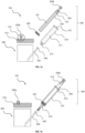
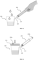
- the fluid collection device (100) generally includes a specimen collection tube assembly (200) and a specimen collection cup (300) (see FIGS. 1a and 1b ).
- the specimen collection tube assembly (200) comprises: a) a barrel (210) having a first chamber (211); and b) an inner tube or plunger (220) having a second chamber (221).
- the barrel (210) is provided with a luer tip (214) at one end, and another end (215) is in slidable sealing engagement with the inner tube (220) defining a closed system thereof.
- the inner tube (220) is provided with a luer tip (224) at one end, and the opposite end is equipped with a seal (222) separating the first and second chambers (211 and 221) in said closed system.
- a conduit (212) is preferably provided at the luer tip (224) of the inner tube (220) extended towards the second chamber (221) in accordance with the first preferred exemplary of the present invention.
- the luer tip (214) of the barrel (210) and the luer tip (224) of the inner tube (220) are releasably provided with at least one luer knob (230a or 230b), such that the luer knob (230a or 230b) can be selectively loosened or tightened for negative pressure release in the closed system to allow fluid drop under the gravity.
- the luer knob (230a or 230b) although an exemplary, will be used herein in describing the configurations and functions of the present invention. However other variations, approaches or configuration, such as an air-tight, tough elastic polymeric substance or materials of same group capable of providing similar mechanical and chemical properties, to obtain desired optimal operating characteristics may be contemplated.
- the luer knob (230a or 230b) as described herein should not be construed as limiting in any way.
- the specimen collection tube assembly (200) is adapted to collaboratively connect with the specimen collection cup (300) for a specimen or fluid collection via a luer lock system.
- the specimen or fluid collection may include urine or the like.
- the specimen collection tube assembly (200) is adapted to independently aspirate a fluid through a hypodermic needle attached to the luer tip (214) of the barrel (210) (not shown).
- the specimen or fluid specifically biological fluid collection may include serum, plasma, blood, saliva, interstitial fluid or cytosol, and the like but not limited to others.
- the specimen collection tube assembly (200) is adapted to be connected to a spout (320) of the specimen collection cup (300) via the luer tip (214) of the barrel (210) (see FIGS. 1b ).
- the spout (320) of the specimen collection cup (300) is provided with a luer lock (340) for fitting engagement with the luer tip (214) of the barrel (210).
- the luer lock (340) may be of a screw type or any leak-free connections, such as male and female mating type of fitting with the luer tip (214) of the barrel (210), and may be altered in a manner so as to obtain desired optimal operating characteristics.
- the specimen collection cup (300) is preferably equipped with a cover (310).
- the cover (310) is preferably provided with a pressure release mechanism (312) to release vacuum or negative pressure within the specimen collection cup (300).
- the pressure release mechanism (312) includes a luer knob (230a) for pressure release during aspiration process.
- the pressure release mechanism (312) is adapted to be activated for aspiration process. Accordingly, the aspiration process is executed only after the pressure release mechanism (312) at the cover (310) of the specimen collection cup (300) is activated.
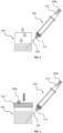
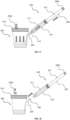
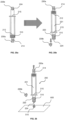
- the specimen collection tube assembly (200) is adapted to aspirate the fluid from the specimen collection cup (300) to the first chamber (211) of the barrel (210) by a vacuum suction created through a pulling action of the inner tube (220) with the luer knob (230b) tightened (see FIGS. 2 to 4 ). It will be appreciated that the aspiration process is further aided by loosening the luer knob (230a) at the cover (310) to release negative pressure in the specimen collection cup (300). At this point, the luer knob (230a) at the cover (310) of the specimen collection cup (300) is loosened to release negative pressure within the specimen collection cup (300). It will be appreciated that the specimen collection tube assembly (200) may serve as a handle for the specimen collection cup (300) for easy handling and collection of the urine specimen or fluid.
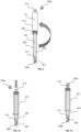
- the fluid is adapted to flow from the first chamber (211) into the second chamber (221) by turning-over the specimen collection tube assembly (200) (see FIG. 6 ), such that barrel (210) end is facing up and inner tube (220) end is facing down; and with the luer knob (230b) tightened at the luer tip (224) of the inner tube (220) whilst leaving the luer tip (214) of the barrel (210) open to allow pressure release from the first chamber (211) of the specimen collection tube assembly (200).
- the barrel (210) will then be fully pushed towards the inner tube (220) of the specimen collection tube assembly (200) and the luer tip (214) of the barrel (210) is being tightened with the luer knob (230a) that is detached from the cover (310) before entering into a centrifuge (400) for fluid separation process (see FIGS. 7a and 7b ).
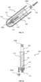
- the specimen collection tube assembly (200) is adapted to be inserted into a centrifuge with the inner tube (220) end facing inside a holder (400) of the centrifuge for the fluid separation process (see FIG. 8 ). It will be appreciated that a layer of specimen residue (500) and a layer of specimen sediment (510) will be obtained through the centrifuge separation process.
- the specimen residue (500) is adapted to be discharged from the second chamber (221) of the inner tube (220) through the conduit (212) to the luer tip (224) of the inner tube (220), while enabling the specimen sediment (510) of at least 1 cc is left remaining in the second chamber (221) of the specimen collection tube assembly (200). It should also be noted that the barrel (210) is being pulled upward leaving a space of approximately or at least 2mm in the first chamber (211) of the specimen collection tube assembly (200).
- the specimen residue (500) can be discharged by releasing the luer knob (230b) at the luer tip (224) of the inner tube (220), while loosening the luer knob (230a) at the luer tip (214) of the barrel (210) to allow negative pressure release from the second chamber (221) of the specimen collection tube assembly (200).
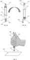
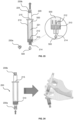
- the specimen sediment (510) is adapted to be discharged from the second chamber (221) of the specimen collection tube assembly (200) through the luer tip (214) of the barrel (210). Accordingly, the specimen sediment (510) can be discharged by turning-over the specimen collection tube assembly (200), such that barrel (210) end is facing down and inner tube (220) end is facing up; by releasing the luer knob (230a) at the luer tip (214) of the barrel (210), and gently press the luer knob (230b) at the luer tip (224) of the inner tube (220) to allow droplets of the specimen sediment (510) to be released from the specimen collection tube assembly (200) (see FIGS. 12a to 13 ).
- the specimen sediment (510) may be discharged by droplets from the specimen collection tube assembly (200) onto Petri dish (600) for microscopic analysis (see FIG. 13 ).
- the fluid collection device (100) generally includes a specimen collection tube assembly (200) and a specimen collection cup (300) (see FIGS. 14a and 14b ).
- the specimen collection tube assembly (200) comprises: a) a barrel (210) having a first chamber (211); and b) an inner tube or plunger (220) having a second chamber (221).
- the barrel (210) is provided with a luer tip (214) at one end, and another end (215) is in slidable sealing engagement with the inner tube (220) defining a closed system thereof.
- the inner tube (220) is the inner tube (220) is provided with a luer tip (224) at one end, and the opposite end is equipped with a seal (222) separating the first and second chambers (211 and 221) in said closed system.
- a conduit (212) is preferably extended from the luer tip (214) of the barrel (210) towards the first chamber (211) in accordance with the second preferred exemplary of the present invention.
- the luer tip (214) of the barrel (210) and the luer tip (224) of the inner tube (220) are releasably provided with at least one luer knob (230a or 230b), such that the luer knob (230a or 230b) can be selectively loosened or tightened for negative pressure release in the closed system to allow fluid drop under the gravity.
- the luer knob (230a or 230b) although an exemplary, will be used herein in describing the configurations and functions of the present invention. However other variations, approaches or configuration, such as an air-tight, tough elastic polymeric substance or materials of same group capable of providing similar mechanical and chemical properties, to obtain desired optimal operating characteristics may be contemplated.
- the luer knob (230a or 230b) as described herein should not be construed as limiting in any way.
- the specimen collection tube assembly (200) is adapted to collaboratively connect with the specimen collection cup (300) for a specimen or fluid collection via a luer lock system.
- the specimen or fluid collection may include urine or the like.
- the specimen collection tube assembly (200) is adapted to independently aspirate a fluid through a hypodermic needle attached to the luer tip (214) of the barrel (210) (not shown).
- the specimen or fluid specifically biological fluid collection may include serum, plasma, blood, saliva, interstitial fluid or cytosol, and the like but not limited to others.
- the specimen collection tube assembly (200) is adapted to be connected to a spout (320) of the specimen collection cup (300) via the luer tip (214) of the barrel (210) (see FIGS. 14b ).
- the spout (320) of the specimen collection cup (300) is provided with a luer lock (340) for fitting engagement with the luer tip (214) of the barrel (210).
- the luer lock (340) may be of a screw type or any leak-free connections, such as male and female mating type of fitting with the luer tip (214) of the barrel (210), and may be altered in a manner so as to obtain desired optimal operating characteristics.
- the specimen collection cup (300) is preferably equipped with a cover (310).
- the cover (310) is preferably provided with a pressure release mechanism (312) to release vacuum or negative pressure within the specimen collection cup (300).
- the pressure release mechanism (312) includes a luer knob (230a) for pressure release during aspiration process.
- the pressure release mechanism (312) is adapted to be activated for aspiration process. Accordingly, the aspiration process is executed only after the pressure release mechanism (312) at the cover (310) of the specimen collection cup (300) is activated.
- the specimen collection tube assembly (200) is adapted to aspirate the fluid from the specimen collection cup (300) to the first chamber (211) of the barrel (210) by a vacuum suction created through a pulling action of the inner tube (220) with the luer knob (230b) tightened (see FIGS. 15 to 17 ). It will be appreciated that the aspiration process is further aided by loosening the luer knob (230a) at the cover (310) to release negative pressure in the specimen collection cup (300). At this point, the luer knob (230a) at the cover (310) of the specimen collection cup (300) is loosened to release negative pressure within the specimen collection cup (300). It will be appreciated that the specimen collection tube assembly (200) may serve as a handle for the specimen collection cup (300) for easy handling and collection of the urine specimen or fluid.
- the flow of fluid from the first chamber (211) into the second chamber (221) can be attained by a pushing action of the inner tube (220) towards the first chamber (211).
- the pushing action of the inner tube (220) towards the first chamber (211) can be attained by tightening the luer knob (230a) that is detached from the cover (310) to the luer tip (214) of the barrel (210), while loosening the luer knob (230b) at the luer tip (224) of the inner tube (220) to allow pressure release from the second chamber (221) of the specimen collection tube assembly (200).
- the luer knob (230b) at the luer tip (224) of the inner tube (220) will then be tightened before entering into a centrifuge (400) for fluid separation process.
- the specimen collection tube assembly (200) is adapted to be inserted into a centrifuge with the barrel (210) end facing inside a holder (400) of the centrifuge for the fluid separation process (see FIG. 21 ). It will be appreciated that a layer of specimen residue (500) and a layer of specimen sediment (510) will be obtained through the centrifuge separation process.
- the specimen residue (500) is adapted to be discharged from the second chamber (221) of the inner tube (220) through the conduit (212) to the luer tip (214) of the barrel (210), while enabling the specimen sediment (510) of at least 1 cc to be left remaining between the conduit (212) in the barrel (210) and the first chamber (211) of the specimen collection tube assembly (200).
- the specimen residue (500) can be discharged by releasing the luer knob (230a) at the luer tip (214) of the barrel (210), while loosening the luer knob (230b) at the luer tip (224) of the inner tube (220) to allow negative pressure release from the second chamber (221) of the specimen collection tube assembly (200).
- the specimen sediment (510) is adapted to be discharged from the second chamber (221) of the specimen collection tube assembly (200) through the luer tip (224) of the inner tube (220). It will be appreciated that the specimen sediment (510) is evenly distributed by shaking the specimen collection tube assembly (200) with luer knobs (230a and 230b) tightened at both ends of the luer tip (214) of the barrel (210) and the luer tip (224) of the inner tube (220) before being discharged (see FIG. 24 ).
- the specimen sediment (510) can be discharged by turning-over the specimen collection tube assembly (200), such that barrel (210) end is facing up and inner tube (220) end is facing down; by releasing the luer knob (230b) at the luer tip (224) of the inner tube (220), while sparingly loosening the luer knob (230a) at the luer tip (214) of the barrel (210) to allow negative pressure release from the second chamber (221) of the specimen collection tube assembly (200) (see FIGS. 25a and 25b).
- FIGS. 25b and 26 show the inverted position of the specimen collection tube assembly (200).
- the specimen sediment (510) may be discharged by droplets from the specimen collection tube assembly (200) onto Petri dish (600) for microscopic analysis (see FIG. 26 ).
Landscapes
- Health & Medical Sciences (AREA)
- Life Sciences & Earth Sciences (AREA)
- Hematology (AREA)
- General Health & Medical Sciences (AREA)
- Animal Behavior & Ethology (AREA)
- Veterinary Medicine (AREA)
- Heart & Thoracic Surgery (AREA)
- Medical Informatics (AREA)
- Molecular Biology (AREA)
- Surgery (AREA)
- Engineering & Computer Science (AREA)
- Pathology (AREA)
- Public Health (AREA)
- Biomedical Technology (AREA)
- Chemical & Material Sciences (AREA)
- Clinical Laboratory Science (AREA)
- Chemical Kinetics & Catalysis (AREA)
- Analytical Chemistry (AREA)
- Pulmonology (AREA)
- Sampling And Sample Adjustment (AREA)
- Investigating Or Analysing Biological Materials (AREA)
Claims (24)
- Ensemble formant tube de collecte d'échantillon (200), comportant :i. un corps (210) définissant une première chambre (211) ayant un embout Luer (214) au niveau d'une extrémité et étant ouvert au niveau de l'autre extrémité ; etii. un tube ou piston intérieur (220) qui est mis en prise de manière étanche et coulissante à l'intérieur du corps (210),caractérisé en ce que :- le tube intérieur (220) définit une deuxième chambre (221) ayant un embout Luer (224) au niveau d'une extrémité et étant ouvert au niveau d'une autre extrémité ; dans lequel l'extrémité ouverte du tube intérieur (220) est en mesure de coulisser à l'intérieur de la première chambre (211) de telle sorte que les chambres (211, 221) permettent un transfert de fluide entre l'une par rapport à l'autre ;- un joint d'étanchéité (222) encercle l'extrémité ouverte du tube intérieur (220) à des fins de mise en prise étanche et coulissante à l'intérieur du corps (210) ;dans lequel un système fermé est défini à l'intérieur du tube intérieur (220) et du corps (210) quand chaque embout Luer (214, 224) est fermé par un bouton Luer (230a, 230b) ; etdans lequel un volume du système fermé est variable en faisant coulisser le tube intérieur (220) à l'intérieur du corps (210).
- Ensemble formant tube de collecte d'échantillon (200) selon la revendication 1, dans lequel chaque bouton Luer (230a, 230b) peut être desserré ou serré de manière sélective à des fins de libération de la pression négative dans le système fermé pour permettre une décharge de fluide.
- Ensemble formant tube de collecte d'échantillon (200) selon la revendication 1, dans lequel un conduit (212) est mis en œuvre au niveau d'au moins l'un des embouts Luer (214, 224) à des fins d'extension vers la chambre correspondante (211, 221).
- Ensemble formant tube de collecte d'échantillon (200) selon la revendication 1, dans lequel le corps (210) et le tube intérieur (220) sont configurés pour aspirer un échantillon ou fluide jusque dans la première chambre (211) au travers de l'embout Luer (214), quand l'embout Luer (224) est fermé au moyen du bouchon Luer (230b) et quand le tube intérieur (220) est tiré à l'opposé du corps (210).
- Ensemble formant tube de collecte d'échantillon (200) selon la revendication 4, dans lequel le corps (210) et le tube intérieur (220) sont configurés pour aspirer l'échantillon ou fluide biologique au travers d'une aiguille hypodermique attachée à l'embout Luer (214) du corps (210).
- Ensemble formant tube de collecte d'échantillon (200) selon la revendication 4, dans lequel le corps (210) et le tube intérieur (220) sont configurés pour aspirer l'échantillon ou fluide biologique par une aspiration sous vide créée par une action de traction du tube intérieur (220) alors que le bouton Luer (230b) est serré sur l'embout Luer (224).
- Ensemble formant tube de collecte d'échantillon (200) selon la revendication 4, dans lequel l'échantillon comprend l'urine.
- Ensemble formant tube de collecte d'échantillon (200) selon la revendication 4, dans lequel le fluide est, de manière spécifique, un fluide biologique sélectionné dans un groupe comprenant du sérum, du plasma, du sang, de la salive, du liquide interstitiel et du cytosol.
- Ensemble formant tube de collecte d'échantillon (200) selon la revendication 4, dans lequel le fluide dans la première chambre (211) s'écoule jusque dans la deuxième chambre (221) au travers de l'extrémité ouverte du tube intérieur (220) quand le corps (210) est orienté vers le haut et que le tube intérieur (220) est orienté vers le bas.
- Ensemble formant tube de collecte d'échantillon (200) selon la revendication 9, dans lequel le corps (210) est poussé à fond vers le tube intérieur (220), le fluide étant dans la deuxième chambre (221), et l'embout Luer (214) du corps (210) est serré avec le bouton Luer (230a) avant de placer l'ensemble formant tube de collecte d'échantillon (200) dans une centrifugeuse (400) pour un processus de séparation de fluide.
- Ensemble formant tube de collecte d'échantillon (200) selon la revendication 10, dans lequel le tube intérieur (220) est orienté vers l'intérieur d'un support (400) de la centrifugeuse (400) quand l'ensemble formant tube de collecte d'échantillon (200) est placé dans la centrifugeuse (400).
- Ensemble formant tube de collecte d'échantillon (200) selon la revendication 4, dans lequel le fluide dans la première chambre (211) s'écoule jusque dans la deuxième chambre (221), quand le corps (210) est orienté vers le bas et que le tube intérieur (220) est poussé vers la première chambre (211), le bouton Luer (230a) étant serré au niveau de l'embout Luer (214) et le bouton Luer (230b) étant desserré de l'embout Luer (224).
- Ensemble formant tube de collecte d'échantillon (200) selon la revendication 12, dans lequel le corps (210) est orienté vers l'intérieur d'un support (400) d'une centrifugeuse (400) quand l'ensemble formant tube de collecte d'échantillon (200) est placé dans une centrifugeuse (400) pour un processus de séparation de fluide.
- Ensemble formant tube de collecte d'échantillon (200) selon la revendication 11 ou la revendication 13, dans lequel, quand le processus de séparation de fluide forme une couche de résidu d'échantillon (500) et une couche de sédiment d'échantillon (510) dans le fluide, un conduit (212) au niveau de l'un des embouts Luer (214, 224) est configuré pour décharger le résidu d'échantillon (500) en provenance de la deuxième chambre (221) et pour retenir au moins 1 cc du sédiment d'échantillon (510) autour du conduit (212).
- Ensemble formant tube de collecte d'échantillon (200) selon la revendication 14, dans lequel le conduit (212) au niveau de l'embout Luer (224) décharge le résidu d'échantillon (500) quand :- l'ensemble formant tube de collecte d'échantillon (200) est positionné, de telle sorte que le tube intérieur (220) est orienté vers le bas ;- le bouton Luer (230b) au niveau de l'embout Luer (224) du tube intérieur (220) est libéré ; et- le bouton Luer (230a) au niveau de l'embout Luer (214) est desserré à des fins de libération de la pression négative en provenance de la deuxième chambre (221).
- Ensemble formant tube de collecte d'échantillon (200) selon la revendication 15, dans lequel le corps (210) est adapté pour être tiré vers le haut afin de laisser un espace mesurant au moins 2 mm dans la première chambre (211) une fois que le résidu d'échantillon (500) est déchargé au travers du conduit (212).
- Ensemble formant tube de collecte d'échantillon (200) selon la revendication 16, dans lequel l'embout Luer (214) est configuré pour décharger le sédiment d'échantillon (510).
- Ensemble formant tube de collecte d'échantillon (200) selon la revendication 14, dans lequel le conduit (212) au niveau de l'embout Luer (214) est configuré pour décharger le résidu d'échantillon (500) quand :- l'ensemble formant tube de collecte d'échantillon (200) est tourné, de telle sorte que le tube intérieur (220) est orienté vers le haut ;- le bouton Luer (230a) au niveau de l'embout Luer (214) du corps (210) est libéré ; et- le bouton Luer (230b) au niveau de l'embout Luer (224) est desserré à des fins de libération de la pression négative en provenance de la deuxième chambre (221).
- Ensemble formant tube de collecte d'échantillon (200) selon la revendication 18, dans lequel l'embout Luer (224) est configuré pour décharger le sédiment d'échantillon (510).
- Ensemble formant tube de collecte d'échantillon (200) selon la revendication 16 ou la revendication 18, dans lequel le corps (210) et le tube intérieur (220) sont configurés pour répartir de manière uniforme le sédiment d'échantillon (510) quand l'ensemble formant tube de collecte d'échantillon (200) est secoué, les boutons Luer (230a, 230b) étant serrés au niveau des embouts Luer correspondants (214, 224) une fois que le résidu d'échantillon (500) est déchargé au travers du conduit (212) .
- Ensemble formant tube de collecte d'échantillon (200) selon la revendication 20, dans lequel l'embout Luer (214) est configuré pour décharger le sédiment d'échantillon (510) quand :• l'ensemble formant tube de collecte d'échantillon (200) est tourné, de telle sorte que le corps (210) est orienté vers le bas et que le tube intérieur (220) est orienté vers le haut ;• le bouton Luer (230a) au niveau de l'embout Luer (214) du corps (210) est libéré ; et• le bouton Luer (230b) au niveau de l'embout Luer (224) du tube intérieur (220) est comprimé afin de permettre à des gouttelettes du sédiment d'échantillon (510) de se décharger au travers de l'embout Luer (214).
- Ensemble formant tube de collecte d'échantillon (200) selon la revendication 20, dans lequel l'embout Luer (224) est configuré pour décharger le sédiment d'échantillon (510) quand :• l'ensemble formant tube de collecte d'échantillon (200) est tourné, de telle sorte que le corps (210) est orienté vers le haut et que le tube intérieur (220) est orienté vers le bas ;• le bouton Luer (230b) au niveau de l'embout Luer (224) du tube intérieur (220) est libéré ; et• le bouton Luer (230a) au niveau de l'embout Luer (214) du corps (210) est desserré de façon modérée à des fins de libération de la pression négative en provenance de la deuxième chambre (221).
- Ensemble formant tube de collecte d'échantillon (200) selon la revendication 20, dans lequel l'ensemble formant tube de collecte d'échantillon (200) est configuré pour décharger le sédiment d'échantillon (510) sous la forme de gouttelettes au travers de l'un des embouts Luer (214, 224) .
- Dispositif de collecte de fluide (100) comportant l'ensemble formant tube de collecte d'échantillon (200) selon la revendication 1 et un flacon de collecte d'échantillon (300) raccordé de manière collaborative à l'ensemble formant tube de collecte d'échantillon (200).
Applications Claiming Priority (2)
| Application Number | Priority Date | Filing Date | Title |
|---|---|---|---|
| MYPI2018703918A MY201866A (en) | 2018-10-23 | 2018-10-23 | A fluid collection device |
| PCT/MY2019/050051 WO2020085893A1 (fr) | 2018-10-23 | 2019-08-30 | Dispositif de collecte de fluide |
Publications (3)
| Publication Number | Publication Date |
|---|---|
| EP3870071A1 EP3870071A1 (fr) | 2021-09-01 |
| EP3870071B1 true EP3870071B1 (fr) | 2023-07-19 |
| EP3870071C0 EP3870071C0 (fr) | 2023-07-19 |
Family
ID=68063003
Family Applications (1)
| Application Number | Title | Priority Date | Filing Date |
|---|---|---|---|
| EP19773957.6A Active EP3870071B1 (fr) | 2018-10-23 | 2019-08-30 | Dispositif de collecte de fluide |
Country Status (6)
| Country | Link |
|---|---|
| US (1) | US12296331B2 (fr) |
| EP (1) | EP3870071B1 (fr) |
| JP (1) | JP7402886B2 (fr) |
| CN (1) | CN112912015B (fr) |
| MY (1) | MY201866A (fr) |
| WO (1) | WO2020085893A1 (fr) |
Families Citing this family (2)
| Publication number | Priority date | Publication date | Assignee | Title |
|---|---|---|---|---|
| US11805995B1 (en) * | 2022-11-22 | 2023-11-07 | King Faisal University | Saliva collection kit |
| CN118718136A (zh) * | 2024-06-27 | 2024-10-01 | 武汉大学人民医院(湖北省人民医院) | 一种用于体液引流管监测的装置及体液监测设备 |
Family Cites Families (20)
| Publication number | Priority date | Publication date | Assignee | Title |
|---|---|---|---|---|
| US701671A (en) * | 1901-08-03 | 1902-06-03 | John A Billings | Hypodermic syringe. |
| US3706305A (en) * | 1971-03-03 | 1972-12-19 | Harold J Berger | Combination blood sampling vacuum syringe centrifuge container and specimen cup |
| JPS54238Y2 (fr) * | 1973-02-12 | 1979-01-08 | ||
| JPS5399197U (fr) * | 1977-01-17 | 1978-08-11 | ||
| US6423237B1 (en) * | 1992-07-28 | 2002-07-23 | Lamina, Inc. | Method and apparatus for manually separating particulate matter from a liquid specimen |
| US6350254B1 (en) * | 1999-08-06 | 2002-02-26 | Becton, Dickinson And Company | Medical device for fluid collection and method to fill multiple specimen tubes |
| US6712792B2 (en) * | 2001-05-02 | 2004-03-30 | Becton, Dickinson And Company | Flashback blood collection needle |
| US6796957B2 (en) * | 2001-07-10 | 2004-09-28 | Myocardial Therapeutics, Inc. | Sterile aspiration/reinjection systems |
| JP4073189B2 (ja) * | 2001-10-10 | 2008-04-09 | 大成化工株式会社 | 用時混合容器 |
| WO2004047651A2 (fr) * | 2002-11-25 | 2004-06-10 | Boston Scientific Limited | Dispositif d'injection, seringue a vis d'utilisation conjointe, et procede de traitement de corps mammalien |
| CA2514673A1 (fr) * | 2005-08-05 | 2007-02-05 | Duoject Medical Systems Inc. | Dispositif de transfert de liquide pour systeme d'administration de produits pharmaceutiques et methode d'utilisation connexe |
| US6997916B2 (en) * | 2004-01-02 | 2006-02-14 | Smiths Medical Asd, Inc. | Fluid transfer holder assembly and a method of fluid transfer |
| US20060039833A1 (en) * | 2004-08-04 | 2006-02-23 | Yong Peter A | Biological specimen collection, transportation, and dispensing system |
| US9581942B1 (en) * | 2005-03-23 | 2017-02-28 | Shippert Enterprises, Llc | Tissue transfer method and apparatus |
| US8491855B2 (en) | 2005-07-28 | 2013-07-23 | Peter A. K. Yong | Safety, biodegradable biological sample collection system |
| CN102998149A (zh) * | 2011-09-16 | 2013-03-27 | 江苏康健医疗用品有限公司 | 负压尿液收集装置 |
| CA2975173A1 (fr) * | 2015-02-03 | 2016-08-11 | Neomed, Inc. | Systeme de collecte de colostrum |
| US20170153165A1 (en) * | 2015-11-30 | 2017-06-01 | Chidozie O. Nwadigo | Syringe assembly for withdrawing two separate portions of fluid following a single engagement with fluid port |
| CN216602926U (zh) * | 2021-11-08 | 2022-05-27 | 中国人民解放军联勤保障部队第九〇四医院 | 一种泌尿科用无菌保护取样器 |
| CN115430020A (zh) * | 2022-11-08 | 2022-12-06 | 山东百多安医疗器械股份有限公司 | 一种带柔性电极的导尿管 |
-
2018
- 2018-10-23 MY MYPI2018703918A patent/MY201866A/en unknown
-
2019
- 2019-08-30 CN CN201980070069.2A patent/CN112912015B/zh active Active
- 2019-08-30 US US17/283,560 patent/US12296331B2/en active Active
- 2019-08-30 WO PCT/MY2019/050051 patent/WO2020085893A1/fr not_active Ceased
- 2019-08-30 JP JP2021548496A patent/JP7402886B2/ja active Active
- 2019-08-30 EP EP19773957.6A patent/EP3870071B1/fr active Active
Also Published As
| Publication number | Publication date |
|---|---|
| JP2022509478A (ja) | 2022-01-20 |
| EP3870071A1 (fr) | 2021-09-01 |
| WO2020085893A1 (fr) | 2020-04-30 |
| US12296331B2 (en) | 2025-05-13 |
| MY201866A (en) | 2024-03-20 |
| US20210387178A1 (en) | 2021-12-16 |
| CN112912015A (zh) | 2021-06-04 |
| EP3870071C0 (fr) | 2023-07-19 |
| CN112912015B (zh) | 2024-10-01 |
| JP7402886B2 (ja) | 2023-12-21 |
Similar Documents
| Publication | Publication Date | Title |
|---|---|---|
| US9480464B2 (en) | Tissue collection system | |
| JP3916869B2 (ja) | 濾過抽出装置及び該装置の利用方法 | |
| US5078970A (en) | Apparatus for withdrawing a liquid sample from a sample vessel and transferring it | |
| WO2011012020A1 (fr) | Boîte à échantillons multifonctionnelle améliorée | |
| JPH01501602A (ja) | 体液の処理において使用する装置 | |
| CN104780848A (zh) | 尿收集和分析设备 | |
| US5084241A (en) | Apparatus including a sample petter tube for obtaining reproducible liquid samples of small volume | |
| US20210187039A1 (en) | Fecal processing device and methods | |
| US20220212189A1 (en) | Oral fluid, saliva and sputum collection device and method | |
| JP2008509392A (ja) | 生物学的試料を採取し、輸送し且つ放出する装置 | |
| US12296331B2 (en) | Fluid collection device | |
| KR102458777B1 (ko) | 생물학적 유체 수집 및 안정화 시스템 | |
| CN216485078U (zh) | 用于从封闭腔室提取流体样品的装置 | |
| CN108414263A (zh) | 粪便样本一体化采集装置及方法 | |
| EP3989839B1 (fr) | Dispositif de collecte d'échantillons | |
| JP2005506532A (ja) | 液体ベースの標本を処理するためのバイアルシステム、および方法 | |
| US5952239A (en) | Cytology chamber with port to receive collection bottle and method of use | |
| EP4070735A1 (fr) | Dispositif de collecte de fluide oral, de salive et d'expectorations | |
| JP2022509478A5 (ja) | 試料採取管アセンブリ、流体採取方法および流体採取装置 | |
| US5509319A (en) | Adapter for pipetter and hypodermic needle | |
| CN206026357U (zh) | 医用液体采集器 | |
| CN205679439U (zh) | 一种一次性尿液标本收集器 | |
| US20240050938A1 (en) | Apparatus for testing a liquid specimen using suction | |
| CA1217919A (fr) | Dispositif et methodes de prelevement repetitif de faibles volumes d'echantillonnage | |
| WO2025051789A1 (fr) | Dispositif de transfert et procédé de transfert pour transférer au moins un volume d'une suspension cellulaire |
Legal Events
| Date | Code | Title | Description |
|---|---|---|---|
| STAA | Information on the status of an ep patent application or granted ep patent |
Free format text: STATUS: UNKNOWN |
|
| STAA | Information on the status of an ep patent application or granted ep patent |
Free format text: STATUS: THE INTERNATIONAL PUBLICATION HAS BEEN MADE |
|
| PUAI | Public reference made under article 153(3) epc to a published international application that has entered the european phase |
Free format text: ORIGINAL CODE: 0009012 |
|
| STAA | Information on the status of an ep patent application or granted ep patent |
Free format text: STATUS: REQUEST FOR EXAMINATION WAS MADE |
|
| 17P | Request for examination filed |
Effective date: 20210427 |
|
| AK | Designated contracting states |
Kind code of ref document: A1 Designated state(s): AL AT BE BG CH CY CZ DE DK EE ES FI FR GB GR HR HU IE IS IT LI LT LU LV MC MK MT NL NO PL PT RO RS SE SI SK SM TR |
|
| DAV | Request for validation of the european patent (deleted) | ||
| DAX | Request for extension of the european patent (deleted) | ||
| STAA | Information on the status of an ep patent application or granted ep patent |
Free format text: STATUS: EXAMINATION IS IN PROGRESS |
|
| 17Q | First examination report despatched |
Effective date: 20220527 |
|
| GRAP | Despatch of communication of intention to grant a patent |
Free format text: ORIGINAL CODE: EPIDOSNIGR1 |
|
| STAA | Information on the status of an ep patent application or granted ep patent |
Free format text: STATUS: GRANT OF PATENT IS INTENDED |
|
| INTG | Intention to grant announced |
Effective date: 20230213 |
|
| GRAS | Grant fee paid |
Free format text: ORIGINAL CODE: EPIDOSNIGR3 |
|
| GRAA | (expected) grant |
Free format text: ORIGINAL CODE: 0009210 |
|
| STAA | Information on the status of an ep patent application or granted ep patent |
Free format text: STATUS: THE PATENT HAS BEEN GRANTED |
|
| AK | Designated contracting states |
Kind code of ref document: B1 Designated state(s): AL AT BE BG CH CY CZ DE DK EE ES FI FR GB GR HR HU IE IS IT LI LT LU LV MC MK MT NL NO PL PT RO RS SE SI SK SM TR |
|
| REG | Reference to a national code |
Ref country code: GB Ref legal event code: FG4D |
|
| REG | Reference to a national code |
Ref country code: CH Ref legal event code: EP |
|
| REG | Reference to a national code |
Ref country code: DE Ref legal event code: R096 Ref document number: 602019033118 Country of ref document: DE |
|
| REG | Reference to a national code |
Ref country code: IE Ref legal event code: FG4D |
|
| U01 | Request for unitary effect filed |
Effective date: 20230814 |
|
| U07 | Unitary effect registered |
Designated state(s): AT BE BG DE DK EE FI FR IT LT LU LV MT NL PT SE SI Effective date: 20230821 |
|
| U20 | Renewal fee for the european patent with unitary effect paid |
Year of fee payment: 5 Effective date: 20230831 |
|
| REG | Reference to a national code |
Ref country code: LT Ref legal event code: MG9D |
|
| PG25 | Lapsed in a contracting state [announced via postgrant information from national office to epo] |
Ref country code: GR Free format text: LAPSE BECAUSE OF FAILURE TO SUBMIT A TRANSLATION OF THE DESCRIPTION OR TO PAY THE FEE WITHIN THE PRESCRIBED TIME-LIMIT Effective date: 20231020 |
|
| PG25 | Lapsed in a contracting state [announced via postgrant information from national office to epo] |
Ref country code: IS Free format text: LAPSE BECAUSE OF FAILURE TO SUBMIT A TRANSLATION OF THE DESCRIPTION OR TO PAY THE FEE WITHIN THE PRESCRIBED TIME-LIMIT Effective date: 20231119 |
|
| PG25 | Lapsed in a contracting state [announced via postgrant information from national office to epo] |
Ref country code: RS Free format text: LAPSE BECAUSE OF FAILURE TO SUBMIT A TRANSLATION OF THE DESCRIPTION OR TO PAY THE FEE WITHIN THE PRESCRIBED TIME-LIMIT Effective date: 20230719 Ref country code: NO Free format text: LAPSE BECAUSE OF FAILURE TO SUBMIT A TRANSLATION OF THE DESCRIPTION OR TO PAY THE FEE WITHIN THE PRESCRIBED TIME-LIMIT Effective date: 20231019 Ref country code: IS Free format text: LAPSE BECAUSE OF FAILURE TO SUBMIT A TRANSLATION OF THE DESCRIPTION OR TO PAY THE FEE WITHIN THE PRESCRIBED TIME-LIMIT Effective date: 20231119 Ref country code: HR Free format text: LAPSE BECAUSE OF FAILURE TO SUBMIT A TRANSLATION OF THE DESCRIPTION OR TO PAY THE FEE WITHIN THE PRESCRIBED TIME-LIMIT Effective date: 20230719 Ref country code: GR Free format text: LAPSE BECAUSE OF FAILURE TO SUBMIT A TRANSLATION OF THE DESCRIPTION OR TO PAY THE FEE WITHIN THE PRESCRIBED TIME-LIMIT Effective date: 20231020 |
|
| PG25 | Lapsed in a contracting state [announced via postgrant information from national office to epo] |
Ref country code: PL Free format text: LAPSE BECAUSE OF FAILURE TO SUBMIT A TRANSLATION OF THE DESCRIPTION OR TO PAY THE FEE WITHIN THE PRESCRIBED TIME-LIMIT Effective date: 20230719 |
|
| REG | Reference to a national code |
Ref country code: CH Ref legal event code: PL |
|
| REG | Reference to a national code |
Ref country code: DE Ref legal event code: R097 Ref document number: 602019033118 Country of ref document: DE |
|
| PG25 | Lapsed in a contracting state [announced via postgrant information from national office to epo] |
Ref country code: ES Free format text: LAPSE BECAUSE OF FAILURE TO SUBMIT A TRANSLATION OF THE DESCRIPTION OR TO PAY THE FEE WITHIN THE PRESCRIBED TIME-LIMIT Effective date: 20230719 |
|
| PG25 | Lapsed in a contracting state [announced via postgrant information from national office to epo] |
Ref country code: SM Free format text: LAPSE BECAUSE OF FAILURE TO SUBMIT A TRANSLATION OF THE DESCRIPTION OR TO PAY THE FEE WITHIN THE PRESCRIBED TIME-LIMIT Effective date: 20230719 Ref country code: RO Free format text: LAPSE BECAUSE OF FAILURE TO SUBMIT A TRANSLATION OF THE DESCRIPTION OR TO PAY THE FEE WITHIN THE PRESCRIBED TIME-LIMIT Effective date: 20230719 Ref country code: ES Free format text: LAPSE BECAUSE OF FAILURE TO SUBMIT A TRANSLATION OF THE DESCRIPTION OR TO PAY THE FEE WITHIN THE PRESCRIBED TIME-LIMIT Effective date: 20230719 Ref country code: CZ Free format text: LAPSE BECAUSE OF FAILURE TO SUBMIT A TRANSLATION OF THE DESCRIPTION OR TO PAY THE FEE WITHIN THE PRESCRIBED TIME-LIMIT Effective date: 20230719 Ref country code: CH Free format text: LAPSE BECAUSE OF NON-PAYMENT OF DUE FEES Effective date: 20230831 Ref country code: SK Free format text: LAPSE BECAUSE OF FAILURE TO SUBMIT A TRANSLATION OF THE DESCRIPTION OR TO PAY THE FEE WITHIN THE PRESCRIBED TIME-LIMIT Effective date: 20230719 Ref country code: MC Free format text: LAPSE BECAUSE OF FAILURE TO SUBMIT A TRANSLATION OF THE DESCRIPTION OR TO PAY THE FEE WITHIN THE PRESCRIBED TIME-LIMIT Effective date: 20230719 |
|
| REG | Reference to a national code |
Ref country code: IE Ref legal event code: MM4A |
|
| PLBE | No opposition filed within time limit |
Free format text: ORIGINAL CODE: 0009261 |
|
| STAA | Information on the status of an ep patent application or granted ep patent |
Free format text: STATUS: NO OPPOSITION FILED WITHIN TIME LIMIT |
|
| 26N | No opposition filed |
Effective date: 20240422 |
|
| PG25 | Lapsed in a contracting state [announced via postgrant information from national office to epo] |
Ref country code: IE Free format text: LAPSE BECAUSE OF NON-PAYMENT OF DUE FEES Effective date: 20230830 |
|
| PG25 | Lapsed in a contracting state [announced via postgrant information from national office to epo] |
Ref country code: IE Free format text: LAPSE BECAUSE OF NON-PAYMENT OF DUE FEES Effective date: 20230830 |
|
| U20 | Renewal fee for the european patent with unitary effect paid |
Year of fee payment: 6 Effective date: 20240820 |
|
| PG25 | Lapsed in a contracting state [announced via postgrant information from national office to epo] |
Ref country code: CY Free format text: LAPSE BECAUSE OF FAILURE TO SUBMIT A TRANSLATION OF THE DESCRIPTION OR TO PAY THE FEE WITHIN THE PRESCRIBED TIME-LIMIT; INVALID AB INITIO Effective date: 20190830 |
|
| PG25 | Lapsed in a contracting state [announced via postgrant information from national office to epo] |
Ref country code: HU Free format text: LAPSE BECAUSE OF FAILURE TO SUBMIT A TRANSLATION OF THE DESCRIPTION OR TO PAY THE FEE WITHIN THE PRESCRIBED TIME-LIMIT; INVALID AB INITIO Effective date: 20190830 |
|
| U20 | Renewal fee for the european patent with unitary effect paid |
Year of fee payment: 7 Effective date: 20250826 |
|
| PGFP | Annual fee paid to national office [announced via postgrant information from national office to epo] |
Ref country code: GB Payment date: 20250826 Year of fee payment: 7 |
|
| PG25 | Lapsed in a contracting state [announced via postgrant information from national office to epo] |
Ref country code: TR Free format text: LAPSE BECAUSE OF FAILURE TO SUBMIT A TRANSLATION OF THE DESCRIPTION OR TO PAY THE FEE WITHIN THE PRESCRIBED TIME-LIMIT Effective date: 20230719 |