EP3870850B1 - Hebesystem zum öffnen eines oberen teils einer gondel - Google Patents
Hebesystem zum öffnen eines oberen teils einer gondel Download PDFInfo
- Publication number
- EP3870850B1 EP3870850B1 EP19875404.6A EP19875404A EP3870850B1 EP 3870850 B1 EP3870850 B1 EP 3870850B1 EP 19875404 A EP19875404 A EP 19875404A EP 3870850 B1 EP3870850 B1 EP 3870850B1
- Authority
- EP
- European Patent Office
- Prior art keywords
- top portion
- nacelle
- rim
- jacks
- pivotally
- Prior art date
- Legal status (The legal status is an assumption and is not a legal conclusion. Google has not performed a legal analysis and makes no representation as to the accuracy of the status listed.)
- Active
Links
Images





Classifications
-
- F—MECHANICAL ENGINEERING; LIGHTING; HEATING; WEAPONS; BLASTING
- F03—MACHINES OR ENGINES FOR LIQUIDS; WIND, SPRING, OR WEIGHT MOTORS; PRODUCING MECHANICAL POWER OR A REACTIVE PROPULSIVE THRUST, NOT OTHERWISE PROVIDED FOR
- F03D—WIND MOTORS
- F03D80/00—Details, components or accessories not provided for in groups F03D1/00 - F03D17/00
- F03D80/80—Arrangement of components within nacelles or towers
-
- F—MECHANICAL ENGINEERING; LIGHTING; HEATING; WEAPONS; BLASTING
- F03—MACHINES OR ENGINES FOR LIQUIDS; WIND, SPRING, OR WEIGHT MOTORS; PRODUCING MECHANICAL POWER OR A REACTIVE PROPULSIVE THRUST, NOT OTHERWISE PROVIDED FOR
- F03D—WIND MOTORS
- F03D80/00—Details, components or accessories not provided for in groups F03D1/00 - F03D17/00
- F03D80/50—Maintenance or repair
-
- B—PERFORMING OPERATIONS; TRANSPORTING
- B66—HOISTING; LIFTING; HAULING
- B66F—HOISTING, LIFTING, HAULING OR PUSHING, NOT OTHERWISE PROVIDED FOR, e.g. DEVICES WHICH APPLY A LIFTING OR PUSHING FORCE DIRECTLY TO THE SURFACE OF A LOAD
- B66F3/00—Devices, e.g. jacks, adapted for uninterrupted lifting of loads
- B66F3/24—Devices, e.g. jacks, adapted for uninterrupted lifting of loads fluid-pressure operated
-
- F—MECHANICAL ENGINEERING; LIGHTING; HEATING; WEAPONS; BLASTING
- F03—MACHINES OR ENGINES FOR LIQUIDS; WIND, SPRING, OR WEIGHT MOTORS; PRODUCING MECHANICAL POWER OR A REACTIVE PROPULSIVE THRUST, NOT OTHERWISE PROVIDED FOR
- F03D—WIND MOTORS
- F03D1/00—Wind motors with rotation axis substantially parallel to the air flow entering the rotor
-
- F—MECHANICAL ENGINEERING; LIGHTING; HEATING; WEAPONS; BLASTING
- F03—MACHINES OR ENGINES FOR LIQUIDS; WIND, SPRING, OR WEIGHT MOTORS; PRODUCING MECHANICAL POWER OR A REACTIVE PROPULSIVE THRUST, NOT OTHERWISE PROVIDED FOR
- F03D—WIND MOTORS
- F03D13/00—Assembly, mounting or commissioning of wind motors; Arrangements specially adapted for transporting wind motor components
- F03D13/10—Assembly of wind motors; Arrangements for erecting wind motors
-
- F—MECHANICAL ENGINEERING; LIGHTING; HEATING; WEAPONS; BLASTING
- F05—INDEXING SCHEMES RELATING TO ENGINES OR PUMPS IN VARIOUS SUBCLASSES OF CLASSES F01-F04
- F05B—INDEXING SCHEME RELATING TO WIND, SPRING, WEIGHT, INERTIA OR LIKE MOTORS, TO MACHINES OR ENGINES FOR LIQUIDS COVERED BY SUBCLASSES F03B, F03D AND F03G
- F05B2230/00—Manufacture
- F05B2230/60—Assembly methods
- F05B2230/61—Assembly methods using auxiliary equipment for lifting or holding
-
- F—MECHANICAL ENGINEERING; LIGHTING; HEATING; WEAPONS; BLASTING
- F05—INDEXING SCHEMES RELATING TO ENGINES OR PUMPS IN VARIOUS SUBCLASSES OF CLASSES F01-F04
- F05B—INDEXING SCHEME RELATING TO WIND, SPRING, WEIGHT, INERTIA OR LIKE MOTORS, TO MACHINES OR ENGINES FOR LIQUIDS COVERED BY SUBCLASSES F03B, F03D AND F03G
- F05B2230/00—Manufacture
- F05B2230/80—Repairing, retrofitting or upgrading methods
-
- F—MECHANICAL ENGINEERING; LIGHTING; HEATING; WEAPONS; BLASTING
- F05—INDEXING SCHEMES RELATING TO ENGINES OR PUMPS IN VARIOUS SUBCLASSES OF CLASSES F01-F04
- F05B—INDEXING SCHEME RELATING TO WIND, SPRING, WEIGHT, INERTIA OR LIKE MOTORS, TO MACHINES OR ENGINES FOR LIQUIDS COVERED BY SUBCLASSES F03B, F03D AND F03G
- F05B2240/00—Components
- F05B2240/10—Stators
- F05B2240/14—Casings, housings, nacelles, gondels or the like, protecting or supporting assemblies there within
-
- Y—GENERAL TAGGING OF NEW TECHNOLOGICAL DEVELOPMENTS; GENERAL TAGGING OF CROSS-SECTIONAL TECHNOLOGIES SPANNING OVER SEVERAL SECTIONS OF THE IPC; TECHNICAL SUBJECTS COVERED BY FORMER USPC CROSS-REFERENCE ART COLLECTIONS [XRACs] AND DIGESTS
- Y02—TECHNOLOGIES OR APPLICATIONS FOR MITIGATION OR ADAPTATION AGAINST CLIMATE CHANGE
- Y02E—REDUCTION OF GREENHOUSE GAS [GHG] EMISSIONS, RELATED TO ENERGY GENERATION, TRANSMISSION OR DISTRIBUTION
- Y02E10/00—Energy generation through renewable energy sources
- Y02E10/70—Wind energy
- Y02E10/72—Wind turbines with rotation axis in wind direction
-
- Y—GENERAL TAGGING OF NEW TECHNOLOGICAL DEVELOPMENTS; GENERAL TAGGING OF CROSS-SECTIONAL TECHNOLOGIES SPANNING OVER SEVERAL SECTIONS OF THE IPC; TECHNICAL SUBJECTS COVERED BY FORMER USPC CROSS-REFERENCE ART COLLECTIONS [XRACs] AND DIGESTS
- Y02—TECHNOLOGIES OR APPLICATIONS FOR MITIGATION OR ADAPTATION AGAINST CLIMATE CHANGE
- Y02P—CLIMATE CHANGE MITIGATION TECHNOLOGIES IN THE PRODUCTION OR PROCESSING OF GOODS
- Y02P70/00—Climate change mitigation technologies in the production process for final industrial or consumer products
- Y02P70/50—Manufacturing or production processes characterised by the final manufactured product
Definitions
- This application relates to wind turbines, in particular to a lift system and method for opening a lid of a nacelle of a wind turbine.
- nacelles In order to remove and/or service large wind turbine components, e.g. generators, main shafts, main bearings, gearboxes and the like, located in a nacelle atop a tower of the wind turbine, the nacelle must be opened sufficiently to be able to remove the turbine components and/or to be able to mount a crane on the nacelle for handling the turbine components.
- Many types of nacelles are constructed in two portions, a bottom portion and an openable top portion (i.e. a lid). The top and bottom portions of the nacelle are attached to one another via bolts at respective rims through internal flanges running along the rims of the top and bottom portion along both sides of the nacelle. To open the top portion, the bolts are removed and a large ground-based crane is sometimes used to lift off the top portion.
- jacking systems have been developed, which can be raised up to the nacelle and mounted inside the nacelle to lift the top portion off the bottom portion.
- Such jacking systems are typified by United States Patent US 9,845,791 issued December 19, 2017 to Liftra IP ApS.
- Such prior art jacking systems comprise four jacks mounted to the lower portion of the nacelle and engaged with the roof of the top portion of the nacelle. Once the bolts connecting the flanges of the top and bottom portions are removed, the top portion is raised by the four jacks and spacers are inserted between the two portions. The four jacks are then lowered and rollers are installed on the sides of the jacks between the two nacelle portions.
- the rollers are engaged with the underside of the flange of the top portion of the nacelle.
- a top roller is then installed above the flange of the top portion thereby providing a roller both below and above the flange of the top portion of the nacelle.
- the top roller prevents the top portion from being blown off the nacelle in the event of a sudden wind gust.
- the top portion can then be slid back along the bottom rollers providing access to the interior of the nacelle from above in order to perform maintenance on the turbine components.
- a lift system that can conveniently open a top portion of a nacelle of a wind turbine when the nacelle has a U-shaped lip on a front of the top portion into which a complementary inverted U-shaped lip of a rotor fairing is inserted.
- a lift system that is able to open a top portion of a nacelle of a wind turbine when the nacelle has a either a substantially rectangular shape or a non-rectangular shape.
- a lift system for opening an openable top portion of a nacelle of a wind turbine, the lift system comprising: first and second laterally spaced apart jacks pivotally connectable to a bottom portion of a nacelle and pivotally connectable to a top portion of the nacelle proximate a rear end of the nacelle, the first and second jacks actuatable to raise and lower a rear of the top portion of the nacelle; and, a support member pivotally connectable to the bottom portion of the nacelle and pivotally connectable to the top portion of the nacelle proximate a front end of the nacelle, a front of the top portion of the nacelle pivotable on the support member when the first and second jacks are actuated to raise or lower the rear of the top portion.
- a method of opening a nacelle of a wind turbine the nacelle having an openable top portion connected to a rotor hub through complementary connecting brackets
- the method comprising: installing first and second jacks inside the nacelle proximate a rear of the nacelle by pivotally connecting the jacks to a bottom portion and the top portion of the nacelle at laterally spaced apart positions in the nacelle; installing a support member inside the nacelle proximate a front of the nacelle by pivotally connecting the support member to the bottom portion and pivotally connecting the support member to the top portion in the nacelle; disconnecting the top portion from the bottom portion along complementary rims of the top and bottom portion; operating the jacks to lift a rear of the top portion thereby causing a front of the top portion to pivot on the support member to tilt the top portion thereby causing the complementary connecting brackets to disconnect; and, shifting the top portion rearward after the complementary connecting brackets are disconnected.
- the lift system utilizes a three-point lifting arrangement inside the nacelle, two points proximate the rear of the nacelle where the jacks connect two points of the bottom portion of the nacelle to two points of an underside of the top portion of the nacelle, and one point proximate the front of the nacelle where the support member connects two points of the bottom portion of the nacelle to one point of an underside of the top portion of the nacelle.
- the jacks and the support member are pivotally connectable to the bottom and top portions by laterally and horizontally oriented pivot pins. In some embodiment, the jacks are pivotally connectable to an underside of the top portion at laterally spaced apart positions. In some embodiments, the support member is pivotally connectable to the underside of the top portion at a single position.
- the support member is a support frame comprising a mounting collar, two legs connected to the mounting collar and an upwardly oriented strut connected to the mounting collar.
- the legs may be connected to and extend angularly downwardly from the mounting collar.
- the legs may have bottom ends that are pivotally connectable to the bottom portion of the nacelle at laterally spaced apart locations.
- the strut may extend upwardly from the mounting collar.
- the strut may have a top end that is pivotally connectable to the top portion of the nacelle.
- the strut may be releasably secured in the mounting collar so that a vertical position of the strut is adjustable.
- the lift system may further comprise rollers mountable on a top rim of the bottom portion to receive a bottom rim of the top portion when the rear of the top portion is lowered.
- the rollers may further permit longitudinal translation of the top portion when the bottom rim of the top portion us supported on the rollers.
- the rollers may be comprised in roller carriages mountable on the top rim of the bottom portion.
- the roller carriages may comprise retainers securely mountable on the bottom portion of the nacelle. The retainers may pivotally connect the roller carriages to the bottom portion to hold the roller carriages on the top rim of the bottom portion while permitting the roller carriages to translate along the top rim.
- the lift system may further comprise sliding plates mountable on the top rim of the bottom portion proximate a rear of the bottom portion.
- the sliding plates may receive the bottom rim of the top portion when the rear of the top portion is lowered.
- the sliding plates may further permit longitudinal translation of the top portion when the bottom rim of the top portion us supported on the sliding plates.
- the method may further comprise installing rollers on the rim of the bottom portion.
- the method may further comprise lowering the rear of the top portion so that the rim of the top portion rests on the rollers.
- the method may further comprise moving the top portion rearward on the rollers to more fully open the nacelle.
- the method may further comprise installing sliding plates on the rim of the bottom portion proximate a rear of the bottom portion. In some embodiments, after the top portion is shifted rearward, the method may further comprise lowering the rear of the top portion so that the rim of the top portion rests on the sliding plates.
- the complementary connecting brackets may comprise a first U-shaped lip on a front of the top portion of the nacelle and a second U-shaped lip on a rotor fairing at a rear of the rotor hub.
- the lift system and method are especially useful for opening the top portion of a nacelle where the top of the nacelle is latched to a hub of the wind turbine at the front of the nacelle by a U-shaped bracket.
- the lift system With the lift system, the rear of the top portion is lifted, the front of the top portion pivots on the support member and the U-shaped bracket unhooks from a complementary U-shaped bracket on the hub during pivoting.
- an operator in the nacelle can shift the top portion a short distance (e.g. about 6-12 inches) to the rear so that the bracket clears the hub.
- Rollers may be installed on a rim of the bottom portion of the nacelle and the top portion lowered down on to the rollers.
- the jacks and support member may then be removed and the top portion may be slid further to the rear of the nacelle so that turbine components in the nacelle (e.g. generator, main shaft, main bearing, gearbox, etc.) can be accessed from above.
- turbine components in the nacelle e.g. generator, main shaft, main bearing, gearbox, etc.
- the lift system is also useful for opening the top portion of a nacelle having either a substantially rectangular shape or a non-rectangular shape, thereby providing the ability to open the top portion of a wider variety of nacelles.
- a longitudinal direction is defined as a direction parallel to a major axis of the nacelle, the major axis of the nacelle running a length of the nacelle and through a hub of the wind turbine.
- a lateral direction is defined as a direction perpendicular to the longitudinal direction in a horizontal plane with respect to the ground.
- a wind turbine 100 comprises a two-part nacelle 101 mounted atop a tower 102, a rotor hub 103 mounted on a front end 105 of the nacelle 101 and rotor blades 104 (only one labeled) mounted on the rotor hub 103.
- the nacelle 101 comprises a bottom portion 106 mounted on the tower 102 and an openable top portion 107 acting as a lid to cover turbine components (e.g. generator, main shaft, main bearing, gearbox, etc.) housed inside the nacelle 101.
- a bottom rim 108 of the top portion 107 comprises a flange that is supported on and bolted to a corresponding flange on a top rim 109 of the bottom portion 106.
- the top portion 107 is therefore supported on and secured to the bottom portion 106 under normal operating conditions.
- the top portion 107 of the nacelle 101 is also removably but sealingly connected at the front end 105 to the hub 103 as described more fully below in connection with Fig. 9A to Fig. 9E .
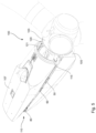
- the nacelle 101 as shown in Fig. 1 is closed while one or more operators inside the nacelle 101 can erect a lift system 1 (see Fig. 2A , Fig. 2B and Fig. 2C ) to assist in lifting and translating the top portion 107 to provide access from above to the turbine components in the nacelle 101.
- the one or more operators erect the lift system 1 by first mounting a pair of jacks 10 and a support frame 30 in the nacelle 101.
- the jacks 10 are erected proximate a rear end 110 of the nacelle 101 and are laterally spaced apart across a width of the nacelle 101 to be on opposite sides of the nacelle 101. Bottom ends 11 of the jacks 10 are pivotally mounted on the bottom portion 106 of the nacelle 101, the jacks 10 oriented upwardly toward the top portion 107 with top ends 12 of the jacks 10 pivotally mounted on the underside of the top portion 107.
- the jacks 10 are operable to extend and retract to permit lifting and lowering a rear of the top portion 107 once the bolts securing the top portion 107 to the bottom portion 106 are removed.
- the jacks 10 are horizontally pinned at the top and bottom ends 11, 12, respectively, to permit some longitudinal translation of the top portion 107 once the bolts securing the top portion 107 to the bottom portion 106 are removed. Further features of the jacks 10 are described below in connection with Fig. 7A to Fig. 7D .
- the support frame 30 is erected proximate the front end 105 of the nacelle 101.
- the support frame 30 comprises two legs 33 that are pivotally mounted on the bottom portion 106 of the nacelle 101 at mounting points that are laterally spaced apart across a width of the nacelle 101 on opposite sides of the nacelle 101.
- the two legs 33 meet at and are connected to a mounting collar 34, the mounting collar 34 located generally centrally between side edges of the nacelle 101.
- the two legs 33 form an angle with the mounting collar 34 at an apex so that the support frame 30 has an inverted V-shape.
- An upwardly oriented strut 35 extending through and releasably secured in the mounting collar 34 has a top end 32 pivotally mounted on the underside of the top portion 107.
- the legs 33 and the strut 35 are horizontally pinned to the bottom and top portions 106, 107, respectively, to permit pivoting of the top portion 107 at the top end 32 of the strut 35 once the bolts securing the top portion 107 to the bottom portion 106 are removed.
- the strut 35 is releasably secured in the mounting collar 34 so that a vertical position of the strut 35 in the mounting collar 34 can be adjusted to accommodate the height of the underside of the top portion 107. Further features of the support frame 30 are described below in connection with Fig. 8A and Fig. 8B .
- jacks 10 are operated to extend thereby lifting the rear of the top portion 107 while the front of the top portion 107 pivots on the support frame 30, as seen in Fig. 3 .
- the top portion 107 becomes angled with respect to the bottom portion 106 creating a gap 111 between the bottom rim 108 of the top portion 107 and the top rim 109 of the bottom portion 106, the gap 111 becoming increasingly larger toward the rear end 110 of the nacelle.
- the roller carriages 50 comprise rollers 51 on which the bottom rim 108 of the top portion 107 can slide when the rear of the top portion 107 is lowered by the jacks 10.
- the rollers 51 may be mounted in a walled cradle 52 of the roller carriage 50 to help prevent lateral movement of the top portion 107 when the top portion 107 is supported on the roller carriages 50.
- the roller carriages 50 further comprise retainers 55 securely mounted on the bottom portion 106 of the nacelle 101.
- the retainers 55 comprise pivotable connecting rods 56 pivotally connecting the retainers 55 to the cradles 52.
- the retainers 55 hold the cradles 52 down on the top rim 109 of the bottom portion 106 while permitting the cradles 52 to translate a small amount along the top rim 109 to provide some flexibility to the position of the rollers 51 relative to the bottom rim 108 of the top portion 107 to prevent jamming of the bottom rim 108 as the top portion 107 slides on the rollers 51.
- the sliding plates 80 are mounted on the top rim 109 of the bottom portion 106 proximate the rear of the bottom portion 109. The sliding plates 80 also receive the bottom rim 108 of the top portion 107 when the jacks 10 lower the rear of the top portion 107.
- the sliding plates 80 support the top portion 107.
- the sliding plates 80 comprise raised lips 81 on outward edges, the raised lips 81 containing the top portion 107 on the sliding plates 80 by preventing excessive lateral movement of the top portion 107 while permitting some lateral movement to prevent jamming of the top portion 107 as the top portion 107 is translated longitudinally.
- the sliding plates 80 are connected across a width of the bottom portion 106 by a brace 89 to provide further structural support for the sliding plates 80.
- the spacers 60 help prevent the bottom rim 108 of the top portion 107 from contacting the top rim 109 of the bottom portion 106 between the roller carriages 50 and the sliding plates 80.
- Each of the jacks 10 has a combined length and stroke length that is sufficient to raise the rear of the top portion 107 enough to permit installation of the other components 50, 60, 80 of the lift system 1 on the top rim 109 of the bottom portion 106, and importantly to result in unhooking of the front of the top portion 107 from the hub 103 when the jacks 10 are extended.
- the jacks 10 are about 8 feet long and have a stroke length of about 7 feet.
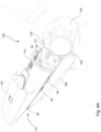
- FIG. 2A , Fig. 2B , Fig. 2C , Fig. 3 , Fig. 4 , Fig. 5 , Fig. 6A and Fig. 6B a process of opening the nacelle 101 using the lift system 1 to provide access from above to the turbine components in the nacelle 101 is depicted.
- the lift system 1 is first installed as described above in connection with Fig. 2A , Fig. 2B and Fig. 2C . As seen in Fig.
- FIG. 9E provide more detailed views of the process of unhooking the U-shaped brackets 115, 121 and moving the top portion 107 about 6-12 inches rearward so that the U-shaped bracket 115 clears the rotor hub 103.
- the operator is able to move the top portion 107 about 6-12 inches because of the lateral horizontal pivoting connections between the jacks 10 and the nacelle 101 (both the top portion 107 and the bottom portion 106) and between the support frame 30 and the nacelle 101 (both the top portion 107 and the bottom portion 106).
- the rear of the top portion 107 is then lowered by retracting the jacks 10 until the bottom rim 108 of the top portion 107 comes to rest on the rollers 51 of the roller carriages 50 and the sliding plates 80.
- An arrangement of chains with chain binders (not shown) is then utilized to brace the top portion 107 of the nacelle 101 from the inside of the nacelle 101 to prevent the top portion 107 from flying off in a strong wind gust.
- the jacks 10 and the support frame 30 are then disconnected from the top portion 107 via the pinned connections. As seen in Fig. 6A and Fig.
- the top portion 107 of the nacelle 101 is then winched rearward along the rollers 51 of the carriages 50. Winching is accomplished by alternately loosening and tightening certain of the chains in the arrangement of chains with chain binders that was installed (not shown). The top portion 107 is winched as far rearward as is necessary to access from above the desired turbine component in the nacelle 101.
- the process is reversed, whereby: the top portion 107 is winched forward until the U-shaped bracket 115 is 6-12 inches away from the complementary U-shaped bracket 121; the jacks 10 and support frame 30 are re-pinned to the top portion 107; the rear of the top portion 107 is raised by the jacks 10 to tilt the front portion 107 so that the front of the top portion 107 is down; the top portion 107 is moved forward so that the U-shaped bracket 115 is aligned for connection with the complementary U-shaped bracket 121; the roller carriages 50, the spacers 60 and the sliding plates 80 are dismounted from the bottom portion 106; and, the rear of the top portion 107 is lowered by the jacks 10 so that the U-shaped bracket 115 and the complementary U-shaped bracket 121 are once again connected and the bottom rim 108 of the top portion 107 and the top rim 109 of the bottom portion 106 are once again mated.
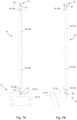
- the jack 10 comprises lower and upper actuators 13, 14, respectively, for example hydraulic cylinders, pneumatic cylinders, linear actuators and the like, attached to one another at actuator barrels 13a, 14a, respectively, to provide sufficient combined length of the actuator barrels 13a, 14a and stroke length of respective actuator rods 13b, 14b.
- the lower actuator 13 is pivotally attached to a lower jack mount 15, the lower jack mount 15 comprising a lower jack mounting bracket 16 to which the lower actuator 13 is pivotally attached and a lower jack mounting plate 17 on which the lower jack mounting bracket 16 is mounted.
- the lower jack mounting bracket 16 and the lower jack mounting plate 17 are monolithic.
- the lower actuator 13 comprises a clevis 18 having opposed apertures and the lower jack mounting bracket 16 comprises at least one corresponding aperture through which a lower jack pin 19 may be inserted to pivotally connect the lower actuator 13 to the lower jack mounting bracket 16.
- the apertures are aligned in a horizontal and lateral direction so that the lower actuator 13 can pivot about a lateral horizontal pivot axis through the lower jack pin 19, thereby permitting the top end 12 of the jack 10 to translate longitudinally.
- the lower jack mounting plate 17 is secured, for example with bolts, to the bottom portion 106 of the nacelle 101.
- the upper actuator 14 comprises a clevis 21 having opposed apertures that may be aligned with at least one aperture in a mounting structure on the underside of the top portion 107.
- An upper jack pin 22 may be inserted through the aligned apertures to pivotally attach the upper actuator 14 to the underside of the top portion 107.
- the apertures are aligned in a horizontal and lateral direction so that the upper actuator 14 can pivot about a lateral horizontal pivot axis through the upper jack pin 22, thereby permitting the top end 12 of the jack 10 to translate longitudinally when the top portion 107 is moved longitudinally to disconnect and reconnect the top portion 107 from and to the hub 103.
- the support frame 30 has the two legs 33 extending angularly downwardly from the mounting collar 34 to provide the support frame 30 with an inverted V-shape with the mounting collar 34 at the apex.
- the upwardly oriented strut 35 extends through and is releasably secured in the mounting collar 34 by a pin 36.
- the pin 36 may be removed so that the upwardly oriented strut 35 can be adjusted vertically to accommodate the height of the top portions of different types of nacelles.
- the upwardly oriented strut 35 comprises a clevis 37 at the top end 32, the clevis 37 having opposed apertures that may be aligned with at least one aperture in a mounting bracket on the underside of the top portion 107.
- An upper support frame pin 38 may be inserted through the aligned apertures to pivotally attach the upwardly oriented strut 35 to the underside of the top portion 107.
- the apertures are aligned in a horizontal and lateral direction so that the upwardly oriented strut 35 can pivot about a lateral horizontal pivot axis through the upper support frame pin 38, thereby permitting the top end 32 of the strut 35 to pivot around the support frame pin 38 when the top portion 107 is moved longitudinally to disconnect and reconnect the top portion 107 from and to the hub 103.
- the legs 33 comprise feet 39 that are pivotally mounted on the bottom portion 106 of the nacelle 101. At the feet 39, the legs 33 are pivotally connected to lower leg mounts 41, the lower leg mounts 41 comprising lower leg mounting brackets 42 and lower leg mounting plates 43 on which the lower leg mounting brackets 42 are mounted. For strength, each lower leg mount 41 is monolithic.
- the lower leg mounting brackets 42 comprise clevises aligned with at least one aperture in the feet 39 of the corresponding legs 33 through which lower support frame pins 44 may be inserted to pivotally secure the legs 33 to the lower leg mounting brackets 42.
- the apertures are aligned in a horizontal and lateral direction so that the legs 33 can pivot about a lateral horizontal pivot axis through the lower support frame pin 44, thereby permitting the top end 32 of the upwardly oriented strut 35 to pivot around the support frame pin 38 without locking up the support frame 30.
- the lower leg mounting plates 43 are secured, for example with bolts, to the bottom portion 106 of the nacelle 101.
- FIG. 9A to Fig. 9E details of the connection between the openable top portion 107 of the nacelle 101 and the rotor hub 103 are depicted.
- the front of the top portion 107 comprises a U-shaped lip 115 into which a complementary inverted U-shaped lip 121 of a rotor fairing 120 on the rotor hub 103 of the wind turbine 100 is inserted, as seen in Fig. 9A and Fig. 9B .
- the connection between the U-shaped lips 115, 121 latches the top portion 107 of the nacelle 101 to the rotor hub 103 and also provides a rain seal for the nacelle 101 under normal working conditions.
- the top portion 107 When the rear of the top portion 107 is raised, the top portion 107 is tilted with the front down, which disconnects the U-shaped lip 115 at the front of the top portion 107 from the complementary U-shaped lip 121 of the rotor fairing 120 on the rotor hub 103, as best seen in Fig. 9C .
- the top portion 107 After tilting the top portion 107, the top portion 107 is shifted rearward about 6-12 inches as seen in Fig. 9D and Fig. 9E , which results in the U-shaped lip 115 at the front of the top portion 107 clearing the complementary U-shaped lip 121 of the rotor fairing 120.
- the rear of the front portion 107 can then be lowered without the U-shaped lip 115 connecting to the complementary U-shaped lip 121 so that the front portion 107 can be winched further rearward to provide access from above to the turbine components in the nacelle 101.
- the combination of the jacks 10, the support frame 30 and the various laterally horizontally pinned connections provides for tilting and a small amount of rearward translation of the top portion 107 of the nacelle 101 to enable unhooking and separation the top portion 107 from the hub 103.
Landscapes
- Engineering & Computer Science (AREA)
- Life Sciences & Earth Sciences (AREA)
- Mechanical Engineering (AREA)
- Sustainable Development (AREA)
- Sustainable Energy (AREA)
- Chemical & Material Sciences (AREA)
- Combustion & Propulsion (AREA)
- General Engineering & Computer Science (AREA)
- Geology (AREA)
- Structural Engineering (AREA)
- Wind Motors (AREA)
- Types And Forms Of Lifts (AREA)
Claims (18)
- Hebesystem (1) zum Öffnen eines öffenbaren oberen Teils (107) einer Gondel (101) einer Windturbine (100), wobei das Hebesystem Folgendes umfasst:einen ersten und einen zweeiten Heber (10), die seitlich beabstandet sind, schwenkbar mit einem unteren Teil (106) einer Gondel verbindbar sind und schwenkbar mit einem oberen Teil (107) der Gondel in der Nähe eines hinteren Endes (110) der Gondel verbindbar sind, wobei der erste und der zweite Heber betätigbar sind, um eine Rückseite des oberen Teils der Gondel anzuheben und abzusenken; undein Stützelement, das schwenkbar mit dem unteren Teil (106) der Gondel (101) verbindbar ist und schwenkbar mit dem oberen Teil (107) der Gondel in der Nähe eines vorderen Endes (105) der Gondel verbindbar ist, wobei eine Vorderseite des oberen Teils der Gondel auf dem Stützelement schwenkbar ist, wenn der erste und der zweite Heber betätigt werden, um die Rückseite des oberen Teils (107) anzuheben oder abzusenken.
- Hebesystem (1) nach Anspruch 1, wobei die Heber (10) und das Stützelement durch seitlich und horizontal ausgerichtete Drehzapfen schwenkbar mit dem unteren (106) und dem oberen Teil (107) verbindbar sind.
- Hebesystem (1) nach Anspruch 1 oder Anspruch 2, wobei die Heber (10) an seitlich beabstandeten Positionen schwenkbar mit einer Unterseite des oberen Teils (107) verbindbar sind und das Stützelement schwenkbar mit der Unterseite des oberen Teils (107) an einer einzigen Position verbindbar ist.
- Hebesystem (1) nach einem der Ansprüche 1 bis 3, wobei das Stützelement ein Stützrahmen (30) ist, der einen Montagering (34), zwei mit dem Montagering verbundene Schenkel (33) und eine nach oben ausgerichtete Strebe (35), die mit dem Montagering (34) verbunden ist, umfasst,wobei die Schenkel (33) mit dem Montagering (33) verbunden sind und sich davon winklig nach unten erstrecken und die Schenkel untere Enden aufweisen, die an seitlich beabstandeten Stellen schwenkbar mit dem unteren Teil (106) der Gondel (101) verbindbar sind, undwobei sich die Strebe (35) von dem Montagering (34) nach oben erstreckt und die Strebe ein oberes Ende (32) aufweist, das schwenkbar mit dem oberen Teil der Gondel (101) verbindbar ist.
- Hebesystem (1) nach Anspruch 4, wobei die Strebe (35) lösbar in dem Montagering (34) befestigt ist, sodass eine vertikale Position der Strebe einstellbar ist.
- Hebesystem (1) nach einem der Ansprüche 1 bis 5, ferner Rollen (51) umfassend, die an einem oberen Rand (109) des unteren Teils (106) montierbar sind, um einen unteren Rand (108) des oberen Teils (107) aufzunehmen, wenn die Rückseite des oberen Teils (107) abgesenkt wird, wobei die Rollen (51) ferner eine Längsverschiebung des oberen Teils ermöglichen, wenn der untere Rand (108) des oberen Teils auf den Rollen (51) gestützt wird.
- Hebesystem (1) nach Anspruch 6, wobei die Rollen (51) in Rollenwagen (50) umfasst sind, die an dem oberen Rand (109) des unteren Teils (106) montierbar sind, wobei die Rollenwagen (50) Halterungen (55) umfassen, die fest an dem unteren Teil (106) der Gondel (101) montierbar sind und die Rollenwagen (50) schwenkbar mit dem unteren Teil (106) verbinden, um die Rollenwagen an dem oberen Rand (109) des unteren Teils (106) zu halten, während sie es den Rollenwagen (50) ermöglichen, sich entlang des oberen Randes (109) zu verschieben.
- Hebesystem (1) nach einem der Ansprüche 1 bis 7, ferner Gleitplatten (80) umfassend, die an dem oberen Rand (109) des unteren Teils (106) nahe einer Rückseite des unteren Teils montierbar sind, wobei die Gleitplatten (80) einen unteren Rand (108) des oberen Teils (107) aufnehmen, wenn die Rückseite des oberen Teils abgesenkt wird, wobei die Gleitplatten (80) ferner eine Längsverschiebung des oberen Teils (107) ermöglichen, wenn der untere Rand (108) des oberen Teils (107) auf den Gleitplatten (80) gestützt wird.
- Verfahren zum Öffnen einer Gondel (101) einer Windturbine (100), wobei die Gondel einen zu öffnenden oberen Teil (107) aufweist und entweder eine im Wesentlichen rechteckige Form oder eine nicht rechteckige Form aufweist, wobei das Verfahren Folgendes umfasst:Installieren eines ersten und eines zweiten Hebers (10) innerhalb der Gondel (101) in der Nähe einer Rückseite der Gondel durch schwenkbares Verbinden der Heber mit einem unteren Teil (106) und dem oberen Teil (107) der Gondel an seitlich voneinander beabstandeten Positionen in der Gondel (101);Installieren eines Stützelements innerhalb der Gondel in der Nähe einer Vorderseite der Gondel durch schwenkbares Verbinden des Stützelements mit dem unteren Teil (106) und schwenkbares Verbinden des Stützelements mit dem oberen Teil (107) in der Gondel (101);Trennen des oberen Teils (107) von dem unteren Teil (106) entlang komplementärer Ränder des oberen (107) und des unteren Teils (106),Betätigen der Heber (10), um eine Rückseite des oberen Teils (107) anzuheben, wodurch bewirkt wird, dass eine Vorderseite des oberen Teils (107) auf dem Stützelement schwenkt, um den oberen Teil zu neigen; undVerschieben des oberen Teils (107) nach hinten.
- Verfahren nach Anspruch 9, wobei der zu öffnende obere Teil (107) über komplementäre Verbindungsklammern mit einer Rotornabe (103) verbunden ist, wobei das Verfahren Folgendes umfasst:Neigen des oberen Teils (107), wodurch bewirkt wird, dass die komplementären Verbindungsklammern getrennt werden, undVerschieben des oberen Teils (107) nach hinten, nachdem die komplementären Verbindungsklammern getrennt wurden.
- Verfahren nach Anspruch 10, wobei die komplementären Verbindungsklammern eine erste U-förmige Lippe (115) an der Vorderseite des oberen Teils (107) der Gondel (101) und eine zweite U-förmige Lippe (121) an einer Rotorverkleidung (120) an einer Rückseite der Rotornabe (103) umfassen.
- Verfahren nach einem der Ansprüche 9 bis 11, wobei die Heber (10) und das Stützelement durch seitlich und horizontal ausgerichtete Drehzapfen schwenkbar mit dem unteren (106) und dem oberen Teil (107) verbunden sind.
- Verfahren nach einem der Ansprüche 9 bis 12, wobei die Heber an den seitlich beabstandeten Positionen schwenkbar mit einer Unterseite des oberen Teils (107) verbunden sind und das Stützelement schwenkbar mit der Unterseite des oberen Teils (107) an einer einzigen Position verbunden ist.
- Verfahren nach einem der Ansprüche 9 bis 13, wobei nach dem Neigen des oberen Teils (107) das Verfahren ferner Installieren von Rollen (51) an dem Rand (109) des unteren Teils (106) umfasst und wobei nach dem Verschieben des oberen Teils (107) nach hinten das Verfahren ferner Absenken der Rückseite des oberen Teils umfasst, sodass der Rand (108) des oberen Teils (107) auf den Rollen liegt.
- Verfahren nach Anspruch 14, ferner umfassend Bewegen des oberen Teils (107) auf den Rollen (51) nach hinten, um die Gondel (101) weiter zu öffnen.
- Verfahren nach einem der Ansprüche 9 bis 15, wobei nach dem Neigen des oberen Teils (107) das Verfahren ferner Installieren von Gleitplatten (80) an dem Rand (109) des unteren Teils (106) in der Nähe einer Rückseite des unteren Teils (106) umfasst und wobei nach dem Verschieben des oberen Teils (107) nach hinten das Verfahren ferner Absenken der Rückseite des oberen Teils (107) umfasst, sodass der Rand (108) des oberen Teils auf den Gleitplatten (80) liegt.
- Verfahren nach einem der Ansprüche 9 bis 16, wobei das Stützelement ein Stützrahmen (30) ist, der einen Montagering (34), zwei mit dem Montagering (34) verbundene Schenkel (33) und eine nach oben ausgerichtete Strebe (45), die mit dem Montagering (34) verbunden ist, umfasst,wobei die Schenkel (33) mit dem Montagering (34) verbunden sind und sich davon winklig nach unten erstrecken und die Schenkel untere Enden (11) aufweisen, die an seitlich beabstandeten Stellen schwenkbar mit dem unteren Teil (106) der Gondel (101) verbunden sind, undwobei sich die Strebe (35) von dem Montagering (34) nach oben erstreckt und die Strebe ein oberes Ende (32) aufweist, das schwenkbar mit dem oberen Teil (107) der Gondel (101) verbunden ist.
- Verfahren nach Anspruch 17, wobei die Strebe (35) lösbar in dem Montagering (34) befestigt ist, sodass eine vertikale Position der Strebe (35) einstellbar ist.
Applications Claiming Priority (2)
| Application Number | Priority Date | Filing Date | Title |
|---|---|---|---|
| US201862749940P | 2018-10-24 | 2018-10-24 | |
| PCT/CA2019/051474 WO2020082167A1 (en) | 2018-10-24 | 2019-10-18 | Lift system for opening a top portion of a nacelle |
Publications (4)
| Publication Number | Publication Date |
|---|---|
| EP3870850A1 EP3870850A1 (de) | 2021-09-01 |
| EP3870850A4 EP3870850A4 (de) | 2022-08-31 |
| EP3870850C0 EP3870850C0 (de) | 2023-11-22 |
| EP3870850B1 true EP3870850B1 (de) | 2023-11-22 |
Family
ID=70330241
Family Applications (1)
| Application Number | Title | Priority Date | Filing Date |
|---|---|---|---|
| EP19875404.6A Active EP3870850B1 (de) | 2018-10-24 | 2019-10-18 | Hebesystem zum öffnen eines oberen teils einer gondel |
Country Status (6)
| Country | Link |
|---|---|
| US (1) | US11221000B2 (de) |
| EP (1) | EP3870850B1 (de) |
| CA (1) | CA3117091C (de) |
| ES (1) | ES2966029T3 (de) |
| PL (1) | PL3870850T3 (de) |
| WO (1) | WO2020082167A1 (de) |
Families Citing this family (5)
| Publication number | Priority date | Publication date | Assignee | Title |
|---|---|---|---|---|
| EP4144986B1 (de) * | 2021-09-06 | 2024-11-06 | General Electric Renovables España S.L. | Windturbinengondel mit mindestens einer verschiebbaren dachplatte |
| EP4166783A1 (de) * | 2021-10-12 | 2023-04-19 | Siemens Gamesa Renewable Energy Innovation & Technology S.L. | Windkraftanlage mit einer gondel mit beweglicher(n) verlängerung(en) |
| WO2024095135A1 (en) * | 2022-11-01 | 2024-05-10 | Liftwerx Europe Holdings B.V. | System and method for opening a nacelle roof panel |
| CN118242235B (zh) * | 2024-03-27 | 2024-11-05 | 新清环境技术(连云港)有限公司 | 一种用于安装机舱罩顶盖的支撑结构 |
| CN119873692B (zh) * | 2025-03-28 | 2025-07-01 | 上海戈洛立科技有限公司 | 一种用于风电机组的机舱罩移动装置及其操作方法 |
Family Cites Families (8)
| Publication number | Priority date | Publication date | Assignee | Title |
|---|---|---|---|---|
| US4757211A (en) * | 1987-07-10 | 1988-07-12 | Danregn Vidraft A/S | Machine for generating electricity |
| US5649392A (en) * | 1990-10-04 | 1997-07-22 | Svenning; Sven | Wind-power plants |
| WO2008104185A1 (en) | 2007-02-28 | 2008-09-04 | Vestas Wind Systems A/S | A support system for a wind turbine component, a vehicle transport system for a wind turbine component and a method for operating a support system |
| US8104631B2 (en) * | 2008-07-24 | 2012-01-31 | General Electric Company | Portable crane system for wind turbine components |
| WO2012105971A1 (en) * | 2011-02-02 | 2012-08-09 | Smith Matthew K | Nacelle-mounted maintenance system for wind turbines |
| US9523347B2 (en) * | 2012-01-18 | 2016-12-20 | Gamesa Innovation & Technology, S.L. | Manual lifting tool for wind turbines |
| DK178900B1 (da) * | 2012-06-04 | 2017-05-08 | Liftra Ip Aps | Fremgangsmåde og midler til etablering af adkomst til hoveddelene i nacellen på en vindmølle |
| JP6351659B2 (ja) * | 2016-05-20 | 2018-07-04 | 三菱重工業株式会社 | 風車用ナセル及び風力発電装置並びに風力発電装置の部品昇降方法 |
-
2019
- 2019-10-18 PL PL19875404.6T patent/PL3870850T3/pl unknown
- 2019-10-18 US US17/286,914 patent/US11221000B2/en active Active
- 2019-10-18 WO PCT/CA2019/051474 patent/WO2020082167A1/en not_active Ceased
- 2019-10-18 ES ES19875404T patent/ES2966029T3/es active Active
- 2019-10-18 EP EP19875404.6A patent/EP3870850B1/de active Active
- 2019-10-18 CA CA3117091A patent/CA3117091C/en active Active
Also Published As
| Publication number | Publication date |
|---|---|
| US20210355920A1 (en) | 2021-11-18 |
| PL3870850T3 (pl) | 2024-03-04 |
| EP3870850C0 (de) | 2023-11-22 |
| EP3870850A4 (de) | 2022-08-31 |
| US11221000B2 (en) | 2022-01-11 |
| WO2020082167A1 (en) | 2020-04-30 |
| EP3870850A1 (de) | 2021-09-01 |
| ES2966029T3 (es) | 2024-04-18 |
| CA3117091C (en) | 2021-08-03 |
| CA3117091A1 (en) | 2020-04-30 |
Similar Documents
| Publication | Publication Date | Title |
|---|---|---|
| EP3870850B1 (de) | Hebesystem zum öffnen eines oberen teils einer gondel | |
| EP3714160B1 (de) | In der gondel einer windturbine montierbares aufzugssystem | |
| US9845791B2 (en) | Method and means for establishing access to the main parts in the nacelle on a wind turbine | |
| US8052396B2 (en) | Method for assembling/dismounting components of a wind power plant | |
| US8590151B2 (en) | System for supporting and servicing a gas turbine engine | |
| EP3504149B1 (de) | Verfahren und vorrichtung zur durchführung von wartungsarbeiten an einer windturbinenkomponente | |
| US8672606B2 (en) | Gas turbine engine and system for servicing a gas turbine engine | |
| AU2003223939A1 (en) | Transportation system for a wind turbine component, vehicle for a transportation system, displacement system, method of establishing a transportation or displacement and use thereof | |
| EP3372550A1 (de) | Hubsystem | |
| CN102674131A (zh) | 用于从燃气轮机辅助间移除扭矩变换器和启动马达的设备 | |
| EP4085195B1 (de) | Windturbinengenerator mit servicebühne und zugehöriges verfahren | |
| US7669724B2 (en) | Common pipelayer frame for multiple machine configurations | |
| CN202936122U (zh) | 变幅定滑轮机构和起重机械 | |
| US9028215B2 (en) | Nacelle main frame structure and drive train assembly for a wind turbine | |
| CN114180467A (zh) | 一种拼装式起吊装置 | |
| CN114370154B (zh) | 连廊施工用可拆装式移动钢平台系统及其使用方法 | |
| CN102674165B (zh) | 从燃气涡轮的辅助隔室移除扭矩变换器和启动马达的方法 | |
| EP4334232B1 (de) | Basis zum tragen eines tragbaren krans und verfahren zum entfernen eines hauptlagers einer windturbine | |
| CN114074899A (zh) | 用于伸缩吊臂的快速装配头及其装配方法 | |
| NL2034923B1 (en) | Crane with luffable boom | |
| US20260028966A1 (en) | Service unit with crane for modular nacelle of a wind turbine and method of using same | |
| CN119947976A (zh) | 用于塔上安装式起重机的基座组件 | |
| CN114044450A (zh) | 一种撑臂系统整体快拆装置和快拆方法及起重机 | |
| KR20180000857U (ko) | 잭업리그 레그용 곤돌라 장착장치 | |
| NZ536544A (en) | Method for assembling/dismounting components of a wind power plant |
Legal Events
| Date | Code | Title | Description |
|---|---|---|---|
| STAA | Information on the status of an ep patent application or granted ep patent |
Free format text: STATUS: THE INTERNATIONAL PUBLICATION HAS BEEN MADE |
|
| PUAI | Public reference made under article 153(3) epc to a published international application that has entered the european phase |
Free format text: ORIGINAL CODE: 0009012 |
|
| STAA | Information on the status of an ep patent application or granted ep patent |
Free format text: STATUS: REQUEST FOR EXAMINATION WAS MADE |
|
| 17P | Request for examination filed |
Effective date: 20210429 |
|
| AK | Designated contracting states |
Kind code of ref document: A1 Designated state(s): AL AT BE BG CH CY CZ DE DK EE ES FI FR GB GR HR HU IE IS IT LI LT LU LV MC MK MT NL NO PL PT RO RS SE SI SK SM TR |
|
| DAV | Request for validation of the european patent (deleted) | ||
| DAX | Request for extension of the european patent (deleted) | ||
| REG | Reference to a national code |
Ref country code: DE Ref legal event code: R079 Free format text: PREVIOUS MAIN CLASS: F03D0080000000 Ipc: F03D0080500000 Ref country code: DE Ref legal event code: R079 Ref document number: 602019042083 Country of ref document: DE Free format text: PREVIOUS MAIN CLASS: F03D0080000000 Ipc: F03D0080500000 |
|
| A4 | Supplementary search report drawn up and despatched |
Effective date: 20220617 |
|
| RIC1 | Information provided on ipc code assigned before grant |
Ipc: B66F 3/24 20060101ALI20220611BHEP Ipc: F03D 1/00 20060101ALI20220611BHEP Ipc: F03D 80/50 20160101AFI20220611BHEP |
|
| RA4 | Supplementary search report drawn up and despatched (corrected) |
Effective date: 20220804 |
|
| GRAP | Despatch of communication of intention to grant a patent |
Free format text: ORIGINAL CODE: EPIDOSNIGR1 |
|
| STAA | Information on the status of an ep patent application or granted ep patent |
Free format text: STATUS: GRANT OF PATENT IS INTENDED |
|
| INTG | Intention to grant announced |
Effective date: 20230720 |
|
| RIN1 | Information on inventor provided before grant (corrected) |
Inventor name: AITKEN, GLEN D. |
|
| GRAS | Grant fee paid |
Free format text: ORIGINAL CODE: EPIDOSNIGR3 |
|
| GRAA | (expected) grant |
Free format text: ORIGINAL CODE: 0009210 |
|
| STAA | Information on the status of an ep patent application or granted ep patent |
Free format text: STATUS: THE PATENT HAS BEEN GRANTED |
|
| AK | Designated contracting states |
Kind code of ref document: B1 Designated state(s): AL AT BE BG CH CY CZ DE DK EE ES FI FR GB GR HR HU IE IS IT LI LT LU LV MC MK MT NL NO PL PT RO RS SE SI SK SM TR |
|
| REG | Reference to a national code |
Ref country code: GB Ref legal event code: FG4D |
|
| REG | Reference to a national code |
Ref country code: CH Ref legal event code: EP |
|
| REG | Reference to a national code |
Ref country code: DE Ref legal event code: R096 Ref document number: 602019042083 Country of ref document: DE |
|
| REG | Reference to a national code |
Ref country code: IE Ref legal event code: FG4D |
|
| U01 | Request for unitary effect filed |
Effective date: 20231207 |
|
| U07 | Unitary effect registered |
Designated state(s): AT BE BG DE DK EE FI FR IT LT LU LV MT NL PT SE SI Effective date: 20231213 |
|
| REG | Reference to a national code |
Ref country code: NO Ref legal event code: T2 Effective date: 20231122 |
|
| PG25 | Lapsed in a contracting state [announced via postgrant information from national office to epo] |
Ref country code: GR Free format text: LAPSE BECAUSE OF FAILURE TO SUBMIT A TRANSLATION OF THE DESCRIPTION OR TO PAY THE FEE WITHIN THE PRESCRIBED TIME-LIMIT Effective date: 20240223 |
|
| PG25 | Lapsed in a contracting state [announced via postgrant information from national office to epo] |
Ref country code: IS Free format text: LAPSE BECAUSE OF FAILURE TO SUBMIT A TRANSLATION OF THE DESCRIPTION OR TO PAY THE FEE WITHIN THE PRESCRIBED TIME-LIMIT Effective date: 20240322 |
|
| REG | Reference to a national code |
Ref country code: ES Ref legal event code: FG2A Ref document number: 2966029 Country of ref document: ES Kind code of ref document: T3 Effective date: 20240418 |
|
| PG25 | Lapsed in a contracting state [announced via postgrant information from national office to epo] |
Ref country code: IS Free format text: LAPSE BECAUSE OF FAILURE TO SUBMIT A TRANSLATION OF THE DESCRIPTION OR TO PAY THE FEE WITHIN THE PRESCRIBED TIME-LIMIT Effective date: 20240322 Ref country code: GR Free format text: LAPSE BECAUSE OF FAILURE TO SUBMIT A TRANSLATION OF THE DESCRIPTION OR TO PAY THE FEE WITHIN THE PRESCRIBED TIME-LIMIT Effective date: 20240223 |
|
| PG25 | Lapsed in a contracting state [announced via postgrant information from national office to epo] |
Ref country code: RS Free format text: LAPSE BECAUSE OF FAILURE TO SUBMIT A TRANSLATION OF THE DESCRIPTION OR TO PAY THE FEE WITHIN THE PRESCRIBED TIME-LIMIT Effective date: 20231122 Ref country code: HR Free format text: LAPSE BECAUSE OF FAILURE TO SUBMIT A TRANSLATION OF THE DESCRIPTION OR TO PAY THE FEE WITHIN THE PRESCRIBED TIME-LIMIT Effective date: 20231122 |
|
| PG25 | Lapsed in a contracting state [announced via postgrant information from national office to epo] |
Ref country code: CZ Free format text: LAPSE BECAUSE OF FAILURE TO SUBMIT A TRANSLATION OF THE DESCRIPTION OR TO PAY THE FEE WITHIN THE PRESCRIBED TIME-LIMIT Effective date: 20231122 |
|
| PG25 | Lapsed in a contracting state [announced via postgrant information from national office to epo] |
Ref country code: SK Free format text: LAPSE BECAUSE OF FAILURE TO SUBMIT A TRANSLATION OF THE DESCRIPTION OR TO PAY THE FEE WITHIN THE PRESCRIBED TIME-LIMIT Effective date: 20231122 |
|
| PG25 | Lapsed in a contracting state [announced via postgrant information from national office to epo] |
Ref country code: SM Free format text: LAPSE BECAUSE OF FAILURE TO SUBMIT A TRANSLATION OF THE DESCRIPTION OR TO PAY THE FEE WITHIN THE PRESCRIBED TIME-LIMIT Effective date: 20231122 Ref country code: SK Free format text: LAPSE BECAUSE OF FAILURE TO SUBMIT A TRANSLATION OF THE DESCRIPTION OR TO PAY THE FEE WITHIN THE PRESCRIBED TIME-LIMIT Effective date: 20231122 Ref country code: RO Free format text: LAPSE BECAUSE OF FAILURE TO SUBMIT A TRANSLATION OF THE DESCRIPTION OR TO PAY THE FEE WITHIN THE PRESCRIBED TIME-LIMIT Effective date: 20231122 Ref country code: CZ Free format text: LAPSE BECAUSE OF FAILURE TO SUBMIT A TRANSLATION OF THE DESCRIPTION OR TO PAY THE FEE WITHIN THE PRESCRIBED TIME-LIMIT Effective date: 20231122 |
|
| REG | Reference to a national code |
Ref country code: DE Ref legal event code: R097 Ref document number: 602019042083 Country of ref document: DE |
|
| PLBE | No opposition filed within time limit |
Free format text: ORIGINAL CODE: 0009261 |
|
| STAA | Information on the status of an ep patent application or granted ep patent |
Free format text: STATUS: NO OPPOSITION FILED WITHIN TIME LIMIT |
|
| 26N | No opposition filed |
Effective date: 20240823 |
|
| U20 | Renewal fee for the european patent with unitary effect paid |
Year of fee payment: 6 Effective date: 20240927 |
|
| U1K | Transfer of rights of the unitary patent after the registration of the unitary effect |
Owner name: LIFTWERX SOLUTIONS INC.; CA |
|
| REG | Reference to a national code |
Ref country code: GB Ref legal event code: 732E Free format text: REGISTERED BETWEEN 20250410 AND 20250416 |
|
| REG | Reference to a national code |
Ref country code: CH Ref legal event code: PL |
|
| PG25 | Lapsed in a contracting state [announced via postgrant information from national office to epo] |
Ref country code: MC Free format text: LAPSE BECAUSE OF FAILURE TO SUBMIT A TRANSLATION OF THE DESCRIPTION OR TO PAY THE FEE WITHIN THE PRESCRIBED TIME-LIMIT Effective date: 20231122 |
|
| PG25 | Lapsed in a contracting state [announced via postgrant information from national office to epo] |
Ref country code: CH Free format text: LAPSE BECAUSE OF NON-PAYMENT OF DUE FEES Effective date: 20241031 |
|
| PGFP | Annual fee paid to national office [announced via postgrant information from national office to epo] |
Ref country code: TR Payment date: 20250930 Year of fee payment: 7 |
|
| U20 | Renewal fee for the european patent with unitary effect paid |
Year of fee payment: 7 Effective date: 20251001 |
|
| PGFP | Annual fee paid to national office [announced via postgrant information from national office to epo] |
Ref country code: GB Payment date: 20251021 Year of fee payment: 7 |
|
| PGFP | Annual fee paid to national office [announced via postgrant information from national office to epo] |
Ref country code: NO Payment date: 20251020 Year of fee payment: 7 |
|
| PGFP | Annual fee paid to national office [announced via postgrant information from national office to epo] |
Ref country code: IE Payment date: 20251020 Year of fee payment: 7 |
|
| PGFP | Annual fee paid to national office [announced via postgrant information from national office to epo] |
Ref country code: PL Payment date: 20251008 Year of fee payment: 7 |
|
| PG25 | Lapsed in a contracting state [announced via postgrant information from national office to epo] |
Ref country code: CY Free format text: LAPSE BECAUSE OF FAILURE TO SUBMIT A TRANSLATION OF THE DESCRIPTION OR TO PAY THE FEE WITHIN THE PRESCRIBED TIME-LIMIT; INVALID AB INITIO Effective date: 20191018 |
|
| PGFP | Annual fee paid to national office [announced via postgrant information from national office to epo] |
Ref country code: ES Payment date: 20251118 Year of fee payment: 7 |
|
| PG25 | Lapsed in a contracting state [announced via postgrant information from national office to epo] |
Ref country code: HU Free format text: LAPSE BECAUSE OF FAILURE TO SUBMIT A TRANSLATION OF THE DESCRIPTION OR TO PAY THE FEE WITHIN THE PRESCRIBED TIME-LIMIT; INVALID AB INITIO Effective date: 20191018 |