EP3870874B1 - Systèmes de ressort à gaz hybride ainsi que meuble présentant un tel système de ressort à gaz hybride - Google Patents
Systèmes de ressort à gaz hybride ainsi que meuble présentant un tel système de ressort à gaz hybride Download PDFInfo
- Publication number
- EP3870874B1 EP3870874B1 EP19795482.9A EP19795482A EP3870874B1 EP 3870874 B1 EP3870874 B1 EP 3870874B1 EP 19795482 A EP19795482 A EP 19795482A EP 3870874 B1 EP3870874 B1 EP 3870874B1
- Authority
- EP
- European Patent Office
- Prior art keywords
- gas pressure
- pressure spring
- force
- gas
- spring system
- Prior art date
- Legal status (The legal status is an assumption and is not a legal conclusion. Google has not performed a legal analysis and makes no representation as to the accuracy of the status listed.)
- Active
Links
Images

Classifications
-
- F—MECHANICAL ENGINEERING; LIGHTING; HEATING; WEAPONS; BLASTING
- F16—ENGINEERING ELEMENTS AND UNITS; GENERAL MEASURES FOR PRODUCING AND MAINTAINING EFFECTIVE FUNCTIONING OF MACHINES OR INSTALLATIONS; THERMAL INSULATION IN GENERAL
- F16F—SPRINGS; SHOCK-ABSORBERS; MEANS FOR DAMPING VIBRATION
- F16F9/00—Springs, vibration-dampers, shock-absorbers, or similarly-constructed movement-dampers using a fluid or the equivalent as damping medium
- F16F9/02—Springs, vibration-dampers, shock-absorbers, or similarly-constructed movement-dampers using a fluid or the equivalent as damping medium using gas only or vacuum
- F16F9/0209—Telescopic
- F16F9/0245—Means for adjusting the length of, or for locking, the spring or dampers
-
- F—MECHANICAL ENGINEERING; LIGHTING; HEATING; WEAPONS; BLASTING
- F16—ENGINEERING ELEMENTS AND UNITS; GENERAL MEASURES FOR PRODUCING AND MAINTAINING EFFECTIVE FUNCTIONING OF MACHINES OR INSTALLATIONS; THERMAL INSULATION IN GENERAL
- F16F—SPRINGS; SHOCK-ABSORBERS; MEANS FOR DAMPING VIBRATION
- F16F15/00—Suppression of vibrations in systems; Means or arrangements for avoiding or reducing out-of-balance forces, e.g. due to motion
- F16F15/02—Suppression of vibrations of non-rotating, e.g. reciprocating systems; Suppression of vibrations of rotating systems by use of members not moving with the rotating systems
- F16F15/023—Suppression of vibrations of non-rotating, e.g. reciprocating systems; Suppression of vibrations of rotating systems by use of members not moving with the rotating systems using fluid means
- F16F15/0232—Suppression of vibrations of non-rotating, e.g. reciprocating systems; Suppression of vibrations of rotating systems by use of members not moving with the rotating systems using fluid means with at least one gas spring
-
- F—MECHANICAL ENGINEERING; LIGHTING; HEATING; WEAPONS; BLASTING
- F16—ENGINEERING ELEMENTS AND UNITS; GENERAL MEASURES FOR PRODUCING AND MAINTAINING EFFECTIVE FUNCTIONING OF MACHINES OR INSTALLATIONS; THERMAL INSULATION IN GENERAL
- F16F—SPRINGS; SHOCK-ABSORBERS; MEANS FOR DAMPING VIBRATION
- F16F15/00—Suppression of vibrations in systems; Means or arrangements for avoiding or reducing out-of-balance forces, e.g. due to motion
- F16F15/02—Suppression of vibrations of non-rotating, e.g. reciprocating systems; Suppression of vibrations of rotating systems by use of members not moving with the rotating systems
- F16F15/023—Suppression of vibrations of non-rotating, e.g. reciprocating systems; Suppression of vibrations of rotating systems by use of members not moving with the rotating systems using fluid means
- F16F15/027—Suppression of vibrations of non-rotating, e.g. reciprocating systems; Suppression of vibrations of rotating systems by use of members not moving with the rotating systems using fluid means comprising control arrangements
-
- F—MECHANICAL ENGINEERING; LIGHTING; HEATING; WEAPONS; BLASTING
- F16—ENGINEERING ELEMENTS AND UNITS; GENERAL MEASURES FOR PRODUCING AND MAINTAINING EFFECTIVE FUNCTIONING OF MACHINES OR INSTALLATIONS; THERMAL INSULATION IN GENERAL
- F16F—SPRINGS; SHOCK-ABSORBERS; MEANS FOR DAMPING VIBRATION
- F16F9/00—Springs, vibration-dampers, shock-absorbers, or similarly-constructed movement-dampers using a fluid or the equivalent as damping medium
- F16F9/32—Details
- F16F9/3292—Sensor arrangements
-
- A—HUMAN NECESSITIES
- A47—FURNITURE; DOMESTIC ARTICLES OR APPLIANCES; COFFEE MILLS; SPICE MILLS; SUCTION CLEANERS IN GENERAL
- A47B—TABLES; DESKS; OFFICE FURNITURE; CABINETS; DRAWERS; GENERAL DETAILS OF FURNITURE
- A47B9/00—Tables with tops of variable height
- A47B9/10—Tables with tops of variable height with vertically-acting fluid cylinder
Definitions
- the invention relates to a hybrid gas pressure spring system.
- the hybrid gas pressure spring system has a gas pressure spring with a cylinder, a piston rod that can be moved in the cylinder in the direction of a movement axis, and a compressed gas chamber for a compressed gas to provide a spring force F S that can be applied to the piston rod.
- gas pressure springs have proven themselves for all types of weight balancing and can be found, for example, in height-adjustable office chairs and office tables, as well as, for example, as a supporting opening and holding device for flaps and hoods in vehicles, airplanes and ships. Even in toolmaking, gas springs can easily replace conventional steel compression springs.
- a gas spring with a temperature-independent extension force which can be used in particular as a lifting and/or supporting element for a cover, in particular of a motor vehicle.
- the gas spring has a housing with a piston rod that extends out of the housing in a sealed manner. Its interior is filled with compressed gas.
- the interior of the gas spring is connected via a connecting line to a pressure-generating unit, which can be driven by an electric motor depending on the temperature or the pressure of the gas in the gas spring.
- a signal representing the pressure of the gas can be sent to a control unit via a signal line from a pressure transmitter in a pressure compensation chamber.
- EP 1 965 994 A2 describes a pneumatically sprung caster wheel mechanism having an air piston, an air reservoir, and air hoses.
- gas springs In practice, the possible uses of gas springs are limited wherever they are subject to changing weight or axial forces.
- gas pressure springs reach their limits with height-adjustable tables whose table top is subject to changing loads from objects placed on it. If the load on the table top exceeds the fixed spring force F S , ie the extension force acting on the piston rod in the direction of its movement axis, of the gas pressure spring, the table height can often only be increased with a correspondingly large amount of force on the part of the user.
- F S fixed spring force
- gas pressure springs have been developed in which the compressed gas chamber can be reduced mechanically via a spindle and a cordless screwdriver that can be connected to the spindle in order to increase the atmospheric gas pressure within the compressed gas chamber, and thus the spring force of the compressed gas spring, as required.
- gas pressure springs are not able to depict dynamically changing load cases with justifiable effort.
- the problem relating to the gas pressure spring system is achieved by a hybrid gas pressure spring system having the features specified in claim 1 .
- the piece of furniture has the features specified in claim 8 .
- the hybrid gas pressure spring system comprises at least one gas pressure spring with a cylinder, a piston rod movable in the cylinder in the direction of a movement axis and with a compressed gas chamber for a compressed gas to provide a spring force F S with which the piston rod can be acted upon.
- Gas springs of this type are pre-assembled and available on the market at low cost.
- the hybrid gas pressure spring system also has a compressed gas reservoir and an electrically actuable or actuated pressure compressor, by means of which the compressed gas contained in the pressure chamber of the gas pressure spring can be conveyed into the compressed gas reservoir.
- the gas pressure spring has a fluid connection via which the compressed gas contained in the compressed gas chamber can be guided out of the gas pressure spring and via the pressure compressor to the compressed gas reservoir.
- the gas pressure springs available on the market are generally equipped with such a fluid connection, especially since the gas pressure springs have to be filled with the respective compressed gas by the manufacturer in order to be functional at all.
- a simple tubular or cartridge-shaped hollow body can be used as the compressed gas reservoir.
- the compressed gas reservoir can be made of metal, a composite material or, if necessary, also of plastic.
- the compressed gas reservoir can be fluidically connected to the pressure chamber of the gas pressure spring via a controllable outlet valve on the outlet side, in order to inject the compressed gas temporarily stored or stored in the compressed gas reservoir into the to conduct pressurized gas chamber.
- the hybrid gas pressure spring system is designed as a closed system.
- the hybrid gas pressure spring system comprises a control device with a pressure sensor for detecting a gas pressure P 2 of the compressed gas prevailing in the compressed gas chamber in order to determine the corresponding spring force F S of the gas pressure spring.
- the control device also includes a sensor for determining an axial force F A directed counter to the spring force F S , the control device being programmed to control the outlet valve and the pressure compressor on the basis of the axial force F A in such a way that the spring force F S and the axial force F A cancel each other out, ie are in equilibrium of forces, or essentially cancel each other out, ie have a (value or) magnitude difference that lies in a predetermined difference interval.
- the force (F R ) resulting from the spring force F S and the axial force F A thus has a predetermined maximum amount.
- the spring force F S to be applied by the gas pressure spring in the event of use is therefore regulated by the control device as a function of the load.
- the spring force F S of the gas pressure spring can be dynamically adapted to the current load case.
- the manual support force required to raise the tabletop, seat or bed surface can be constant or im essentially be kept constant.
- the compressed gas reservoir and the pressure chamber are each filled with compressed gas G.
- the compressed gas is preferably nitrogen.
- the gas pressure in the compressed gas reservoir and the gas pressure in the compressed gas chamber preferably match.
- the gas pressure in the compressed gas chamber has its maximum pressure value P 2max .
- the spring force F S of the gas pressure spring is therefore at its maximum.
- the gas pressure spring is parameterized in such a way that the axial forces to be expected in operational use are generally smaller than the specified maximum spring force of the gas pressure spring.
- compressed gas G can be transferred from the compressed gas chamber into the compressed gas reservoir during operation. Due to the resulting pressure drop between the gas pressure prevailing in the compressed gas reservoir and the gas pressure prevailing in the compressed gas chamber, the compressed gas can automatically flow into the compressed gas chamber of the gas pressure spring when the outlet valve is opened.
- the adjustment speed of conventional gas pressure spring systems can still be achieved.
- the hybrid gas pressure spring system also offers advantages when the hybrid gas pressure spring system is used in other areas, for example to support the opening or to hold flaps or hoods, for example in vehicles, ships or aircraft.
- the hybrid gas pressure spring system is also advantageous in the medical sector, for example for stand-up aids or patient beds or stretchers, such as those used in rescue services and patient transport.
- the gas pressure spring is provided with a blocking unit, with the pressure compressor and the outlet valve being able to be activated by the control device only when the blocking unit is activated.
- the blocking unit can only be released when the spring force F S and the axial force F A cancel each other out or their absolute difference D is within the predetermined difference interval.
- the blocking unit can comprise an electromotive actuator which can be controlled by the control device.
- the electromotive actuator can be designed, for example, as a linear motor, like this one on the market is available cheaply.
- An electromagnetic plunger coil actuator or a DC magnet lifting or pulling actuator are also conceivable.
- the hybrid gas pressure spring system even allows the execution of a controlled pre-stroke movement and/or insertion movement of the piston rod out of/into the cylinder of the gas pressure spring. This is advantageous for the range of applications of the hybrid gas pressure spring system. It goes without saying that in this case the blocking unit must be able to be transferred or held by the control device into its release position releasing the movement of the piston rod. This can be implemented, for example, with the electrically operated actuator explained above.
- the pressure compressor can be designed in particular in the form of a piston compressor. Piston compressors of this type are available at low cost to purchase and also to maintain and have a sufficiently long service life. Such a piston compressor can in particular be designed as a double-stroke piston compressor. As a result, a high performance of the pressure compressor can be guaranteed with a particularly compact size.
- the pressure compressor can also be designed as a rotary piston compressor, which can offer advantages in particular in the case of a hybrid gas pressure spring system that is to be designed very dynamically.
- the hybrid gas pressure spring system requires an electrical energy source in operational use.
- the public power grid is particularly suitable as an electrical energy source.
- the hybrid gas pressure spring system can include an electrical energy store, which is designed, for example, in the form of an accumulator, a fuel cell or a capacitor with a corresponding electrical capacitance.
- the pressure compressor can have a mechanical interface for connecting a (hand) crank or a cordless screwdriver exhibit.
- the functionality of the hybrid gas pressure spring system can be maintained as a temporary measure.
- the pressure compressor and the gas pressure spring according to the invention preferably form a unit that can be handled together. Very particularly preferably, these components have a common housing. This can also counteract incorrect installation of the hybrid gas pressure spring system.
- the pressure sensor for detecting the atmospheric gas pressure P 2 of the compressed gas G prevailing in the pressure accumulator at a measurement time can, according to the invention, be embodied in particular as an absolute pressure sensor. It should be noted that the pressure sensor can in principle also be designed as a differential pressure sensor or a bidirectional-differential pressure sensor, which are available on the market in suitable designs at low cost.
- the sensor for determining the axial force F A directed counter to the spring force F S can be, for example, a piezoelectric pressure sensor or a pressure sensor in the form of a bending beam.
- the compressed gas can in particular be nitrogen.
- gases in particular inert gases, can also be used depending on need and requirement profile.
- the piece of furniture according to the invention can be designed, for example, as an (office) table, a workbench or also as a height-adjustable chair with a hybrid gas pressure spring system explained above or have a flap that is movement-coupled to the gas pressure spring of a hybrid gas pressure spring system explained above.
- the hybrid gas pressure spring system can be used in vehicles such as passenger cars, trucks or agricultural machinery, Ships and aircraft are used to support the opening of a flap or a hood (engine or cover) and to support it in its open position.
- the hybrid gas pressure spring system according to the invention can also be used for patient couches or stretchers, such as those used in rescue services and patient transport.
- a further area of application are stand-up aids, which enable or facilitate people with restricted mobility to get up from a deep sitting or lying position.
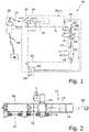
- FIG 1 shows a functional diagram of a hybrid gas pressure spring system 10.
- the hybrid gas pressure spring system 10 comprises a gas pressure spring 12 of a type known per se with a cylinder 14, a piston rod 16 with a piston 18 which is movably mounted in the cylinder 14 in the direction of a movement axis 20 .
- a compressed gas chamber 22 for a compressed gas G is formed in the cylinder 14 .
- the compressed gas G serves to provide a spring force F S , with which the piston rod 16 of the gas pressure spring 12 can be acted upon in a direction axial to the movement axis 20 .
- the spring force F S is therefore directed in the forward stroke direction of the piston rod 16 .
- the hybrid gas spring system 10 further comprises a pressure compressor 24 operated by an electric motor and a compressed gas reservoir 26.
- An electric motor 28 is used to operate the pressure compressor 24.
- the pressure compressor 24 is designed here purely by way of example as a double-stroke piston compressor with a double-stroke piston 32 guided in a compressor tube 30 .
- the double reciprocating piston 32 is coupled to the drive shaft 34 of the electric motor 28 via a connecting rod 36 .
- An electrical connection line 40 is used to connect the electric motor 28 to an electrical energy source 38.
- the electrical energy source 38 is formed by the public power supply network.
- the electrical energy source 38 can also be in the form of a battery, an accumulator or a fuel cell.
- the pressure compressor 24 has an interface 41 for connecting a hand crank or a cordless screwdriver, which can be formed, for example, by the drive shaft of the electric motor.
- a hand crank or a cordless screwdriver which can be formed, for example, by the drive shaft of the electric motor.
- the electromotive pressure compressor 24 can also be designed in the form of a single-stroke piston compressor or a rotary piston compressor can.
- the respective design of the pressure compressor 24 depends, among other things, on the actual technical operating conditions and the size of the hybrid gas pressure spring system 10.
- the pressure compressor 24 is fluidically connected to the compressed gas chamber 22 of the gas pressure spring 12 via a first gas line 42 .
- the pressure compressor 24 serves to transport the compressed gas G contained in the pressure chamber 22 into the compressed gas reservoir 26 when required.
- the compressed gas reservoir 26 and also the pressure compressor 24 can each or together be designed as a component separate from the gas pressure spring 12 . It should be noted that the atmospheric gas pressure P 1 inside the pressurized gas reservoir 26 is always equal to or greater than the atmospheric gas pressure P 2 in the pressurized gas chamber 22 at all times.
- the compressed gas reservoir 26 can be connected fluidically to the compressed gas chamber 22 of the gas pressure spring 12 on the outlet side via a controllable outlet valve 44 and a further gas line 46 in order to conduct the compressed gas G stored in the compressed gas reservoir 26 from the compressed gas reservoir 26 into the pressure chamber 22 as required.
- a control device 48 is used to control the pressure compressor 24 and the outlet valve 44 .
- the control device 48 here has a computing unit 50 and an electronic memory 52 associated with the computing unit 50 .
- Operating software and application software (not shown) can be stored in memory 52 .
- the control device 48 includes a pressure sensor 53 for determining or measuring the gas pressure P 2 of the compressed gas D prevailing in the compressed gas chamber 22, by means of which the spring force F S corresponding to the gas pressure P2 can be determined by the control device 48.
- the pressure sensor can be designed in particular as a so-called absolute pressure sensor.
- the control device 48 also includes a sensor 54 for determining an axial force F A acting in the opposite direction to the spring force F S of the gas pressure spring 12 .
- the sensor 54 serves to detect the actual load on the gas pressure spring 12 .
- the sensor 54 can in particular be designed as a piezoelectric element, for example a pressure sensor, or as a bending beam force sensor, with which the axial force F A directed counter to the spring force F S can be measured.
- the resultant force acting on the piston rod can be directed in the forward stroke direction or in the insertion direction of the piston rod.
- the predefined difference interval can be stored, for example, in the storage unit 52 . It goes without saying that the aforementioned difference interval can advantageously be changed in a variable manner in order to be able to adapt the hybrid gas pressure spring system 10 to different tasks.
- the gas pressure spring 12 is assigned a locking or blocking unit 56 by means of which the piston rod 16 can be fixed in its respective axial position relative to the cylinder 14 of the gas pressure spring 12 .
- the blocking unit 56 can include an electrically actuable actuator 58, for example in the form of a linear motor or an electromagnetic plunger coil actuator or a DC magnet lifting or pulling actuator.
- the control device 48 and the blocking unit 56 interact in such a way that activating the outlet valve 44 or the pressure compressor 24 is only possible when the blocking unit 56 is activated, ie when the piston rod 16 is blocked. This can be achieved, for example, by the control device 48 being programmed to convert the blocking unit 56 or its actuator 58 into the blocking position blocking the adjustment movement of the piston rod 16 before the outlet valve 44/the pressure compressor 24 is actuated.
- the blocking unit 56 can only be unlocked, i.e. transferred to its operating state releasing the axial adjustment of the piston rod 16 relative to the cylinder 14, if the spring force F S and the axial force F A cancel each other out or their absolute difference D lies in the predetermined difference interval .
- the blocking unit 56 can only be unlocked when the gas pressure spring 12 essentially compensates for the axial force F S .
- the compressed gas reservoir and the compressed gas chamber 22 are each filled with compressed gas G.
- the gas pressure P 1 in the compressed gas reservoir 26 and the gas pressure P 2 in the compressed gas chamber 22 match.
- the gas pressure P 1 , P 2 can have its maximum pressure value P 2max .
- the spring force F S of the gas pressure spring is therefore at its maximum.
- the gas pressure spring 12 is parameterized in such a way that the axial forces F A to be expected during operation are generally smaller than the specified maximum spring force F S of the gas pressure spring 12.
- Compressed gas G can thus be transferred from the compressed gas chamber 22 into the compressed gas reservoir 26 for setting the force balance or approximate force balance between the spring force F S and the axial force F S .
- the spring force F S of the gas pressure spring 12 can then be dynamically adjusted by regulating the gas pressure P 2 in the compressed gas chamber 22 to a value that corresponds or essentially corresponds to the actual axial force F A .
- the hybrid gas spring system 10 can be implemented as a single structural unit.
- the assembly of the hybrid gas pressure spring system 10 can be simplified and any existing simple gas pressure springs 12 can be replaced by the hybrid gas pressure spring system 10 .
- the gas pressure spring 12 and the pressure compressor 24 and the compressed gas reservoir 26 can be arranged one behind the other in an axial direction relative to the movement axis 20 of the piston rod 16 of the gas pressure spring 12 .
- the individual assemblies are preferably mechanically coupled to one another in a detachable manner in order to simplify any maintenance or replacement of individual assemblies that may become necessary.
- the aforementioned assemblies can also be housed in a common housing 60 .
- the hybrid gas pressure spring system 10 allows a need-based adjustment of the spring force F S of the gas pressure spring 12 to the load to be taken up by the gas pressure spring 12 in each case. As a result, the hybrid gas pressure spring system 10 has a wide range of technical applications.
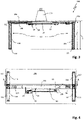
- a piece of furniture 100 is shown in the form of a height-adjustable table with a hybrid gas pressure spring system 10, the operation of which corresponds to the hybrid gas pressure spring system 10 1 is equivalent to.
- the table has a table frame 102 with a table top 104 mounted on the table frame 102 .
- the table frame 102 includes here, purely by way of example, several telescoping table legs 106, which can be adjusted in a synchronized manner in their extension length I.
- the table legs 106 are forcibly coupled to one another for movement via a synchronizing means 108, here a synchronizing shaft. According to 2 the table legs 106 can be connected to one another via a so-called crossbar 110 .
- Table top brackets 112 can be arranged on the table legs 106 or on the crossbar 110 in order to adequately support the table top 104 on the table frame 102 .
- the table legs 106 can, for example, have skid-like table feet 114 and be designed in a T shape or in a C shape.
- the hybrid gas pressure spring system 10 is used analogously to the gas pressure springs known from practice for a simplified height adjustment of the piece of furniture 100.
- the gas pressure spring 12 offers a holding function for the table top 104 in its respective set vertical height h, in particular also when the blocking unit 56 is unlocked (cf. 1 ), if available.
- the gas pressure spring 12 is coupled in a manner known per se at one end, preferably with its piston rod 16, to the synchronizing means 108 for movement.
- the spring force F S ( 1 ) of the gas pressure spring 12 of the hybrid gas pressure spring system 10 is controlled by the control device 48 as a function of the axial force F A ( 1 ), which is co-determined by the total mass of objects 116 arranged on the piece of furniture 100, here the tabletop 104, and changes proportionally thereto. It can thereby be ensured that the table top 104—when the blocking unit 56 is arranged in the release position—is held in suspension by the gas pressure spring 12 independently of its respective vertical position. In order to adjust the height of the table, the user always has to exert the same amount of force, regardless of the respective load on the table top 104 .
- the hybrid gas pressure spring system 10 can be used equally with other pieces of furniture 100, in particular those with a furniture flap provided with at least one gas pressure spring 12 and the like.
- a further field of application for the hybrid gas pressure spring system 10 is in motor vehicles, ships or even airplanes, in which flaps or hoods are to be provided with a gas pressure spring for holding open or damping the adjustment movement of the flap.
- FIG 5 is an example of a motor vehicle 200 with a hinged to the body 202 hood or (tail)gate 204 shown with a above in connection with 1 respectively. 2 explained hybrid gas spring system 10 is provided. Regardless of a snow load acting on the flap 204 or the total mass of objects arranged on the parcel shelf 206 that is motion-coupled to the flap 204, the flap 204 can Floating balance must be maintained so that it can neither open nor fall too quickly.
Landscapes
- Engineering & Computer Science (AREA)
- General Engineering & Computer Science (AREA)
- Mechanical Engineering (AREA)
- Physics & Mathematics (AREA)
- Acoustics & Sound (AREA)
- Aviation & Aerospace Engineering (AREA)
- Fluid-Damping Devices (AREA)
Claims (8)
- Système hybride (10) à ressort pneumatique, comprenant :- un ressort pneumatique (12) incluant un cylindre (14), une tige (16) de piston logée dans ledit cylindre (14) avec mobilité dans la direction d'un axe de mouvement (16), et une chambre (22) à gaz comprimé, destinée à un gaz comprimé (G) conçu pour fournir une force élastique (FS) par laquelle ladite tige (16) de piston peut être sollicitée ;- un accumulateur (26) de gaz comprimé ;- un compresseur (24) actionnable électriquement, au moyen duquel le gaz comprimé (G), renfermé par ladite chambre (22) à gaz comprimé, peut être convoyé pour affluer dans ledit accumulateur (26) de gaz comprimé ;- une vanne de sortie (44) pilotable, par l'intermédiaire de laquelle l'accumulateur (26) de gaz comprimé peut être mis en liaison fluidique avec la chambre (22) à gaz comprimé, de manière à guider le gaz comprimé (G) vers ladite chambre (22) à gaz comprimé, en provenance dudit accumulateur (26) de gaz comprimé ; et- un dispositif de commande (48) comportant un capteur de pression (53) affecté à la détection d'une pression (P2) du gaz comprimé (G) prédominant respectivement dans la chambre (22) à gaz comprimé, en vue de spécifier la force élastique (FS) correspondant à ladite pression gazeuse (P2), et un capteur (54) affecté à la spécification d'une force axiale (FA) dirigée à l'opposé de ladite force élastique (FS), sachant queledit dispositif de commande (48) est programmé pour piloter la vanne de sortie (44) et le compresseur (24), sur la base de la force axiale (FA) spécifiée, de façon telle que ladite force élastique (FS) et ladite force axiale (FA) soient en équilibre, ou présentent une différence de valeurs située dans un intervalle différentiel préétabli ; et sachant que le ressort pneumatique (12) est muni d'une unité de blocage (56) et que ledit compresseur (24) ainsi que ladite vanne de sortie (44) peuvent être pilotés, par ledit dispositif de commande (56), uniquement lorsque l'unité de blocage (56) est activée, ou bien que ladite unité de blocage (56) peut être relâchée uniquement lorsque ladite force élastique (FS) et ladite force axiale (FA) s'annulent mutuellement ou lorsque la différence (D), entre leurs valeurs, se situe dans ledit intervalle différentiel préétabli.
- Système hybride (10) à ressort pneumatique, selon la revendication 1, caractérisé par le fait que l'unité de blocage (56) inclut un actionneur électromotorisé (58) pouvant être piloté par le dispositif de commande (48).
- Système hybride (10) à ressort pneumatique, selon la revendication 1, caractérisé par le fait que le compresseur (24) est un compresseur à piston, ou un compresseur à piston rotatif.
- Système hybride (10) à ressort pneumatique, selon la revendication 1, caractérisé par le fait que le compresseur (24) et le ressort pneumatique (12) forment une unité structurelle commune et présentent un boîtier commun (60).
- Système hybride (10) à ressort pneumatique, selon l'une des revendications précédentes, caractérisé par le fait que le capteur (54) est un capteur de pression/force, au moyen duquel peut être détectée la force axiale (FA) agissant en opposition à la force élastique (FS).
- Article d'ameublement (100) équipé d'un système hybride (10) à ressort pneumatique réalisé en conformité avec l'une des revendications précédentes.
- Article d'ameublement (100) selon la revendication 6, caractérisé par le fait que ledit article d'ameublement est une table réglable en hauteur.
- Article d'ameublement (100) selon la revendication 6 ou 7, caractérisé par le fait que le capteur (54) est réalisé sous la forme d'une barrette de flexion.
Applications Claiming Priority (2)
| Application Number | Priority Date | Filing Date | Title |
|---|---|---|---|
| DE102018218022.9A DE102018218022B4 (de) | 2018-10-22 | 2018-10-22 | Hybridgasdruckfedersystem sowie Möbelstück mit einem solchen Hybridgasdruckfedersystem |
| PCT/EP2019/078549 WO2020083827A1 (fr) | 2018-10-22 | 2019-10-21 | Systèmes de ressort à gaz hybride ainsi que meuble présentant un tel système de ressort à gaz hybride |
Publications (2)
| Publication Number | Publication Date |
|---|---|
| EP3870874A1 EP3870874A1 (fr) | 2021-09-01 |
| EP3870874B1 true EP3870874B1 (fr) | 2022-12-21 |
Family
ID=68392954
Family Applications (1)
| Application Number | Title | Priority Date | Filing Date |
|---|---|---|---|
| EP19795482.9A Active EP3870874B1 (fr) | 2018-10-22 | 2019-10-21 | Systèmes de ressort à gaz hybride ainsi que meuble présentant un tel système de ressort à gaz hybride |
Country Status (3)
| Country | Link |
|---|---|
| EP (1) | EP3870874B1 (fr) |
| DE (1) | DE102018218022B4 (fr) |
| WO (1) | WO2020083827A1 (fr) |
Cited By (1)
| Publication number | Priority date | Publication date | Assignee | Title |
|---|---|---|---|---|
| WO2025082568A1 (fr) * | 2023-10-19 | 2025-04-24 | Stabilus Gmbh | Dispositif de réglage pour trappe mobile, en particulier pour trappe de véhicule |
Families Citing this family (4)
| Publication number | Priority date | Publication date | Assignee | Title |
|---|---|---|---|---|
| EP3868252B1 (fr) * | 2020-02-20 | 2022-06-22 | RealThingks GmbH | Dispositif de réception ainsi que procédé de commande d'un frein agissant sur une unité de réception réglable en hauteur d'un dispositif de réception |
| DE102020211523A1 (de) | 2020-09-14 | 2022-03-17 | Kesseböhmer Holding Kg | Gasfedersystem für einen höhenverstellbaren Tisch, höhenverstellbarer Tisch und Verfahren zum Betreiben des Gasfedersystems |
| DE102021114152A1 (de) | 2021-06-01 | 2022-12-01 | Frank Stiehler | Kraft-, insbesondere lastunabhängige Verstellvorrichtung mit einer Energiespeichervorrichtung |
| DE102021114153A1 (de) | 2021-06-01 | 2022-12-01 | REISS Büromöbel GmbH | Höhenverstellbarer Tisch mit lastunabhängiger Kraft-Last-Verstellvorrichtung |
Family Cites Families (4)
| Publication number | Priority date | Publication date | Assignee | Title |
|---|---|---|---|---|
| DE3902361A1 (de) * | 1989-01-27 | 1990-08-02 | Bauer Fritz & Soehne Ohg | Gasfeder mit temperaturunabhaengiger ausschubkraft |
| US5379980A (en) | 1991-12-23 | 1995-01-10 | Newport Corporation | Stabilization systems for vibration isolators |
| US20070152409A1 (en) * | 2005-12-29 | 2007-07-05 | Emiph, Llc | Method and apparatus for a low-profile suspension system |
| CN105358861B (zh) | 2013-05-13 | 2017-09-12 | 凯斯宝玛制造有限责任公司 | 可调的气压弹簧,具有气压弹簧的高度可调柱,以及具有高度可调柱的家具 |
-
2018
- 2018-10-22 DE DE102018218022.9A patent/DE102018218022B4/de not_active Expired - Fee Related
-
2019
- 2019-10-21 EP EP19795482.9A patent/EP3870874B1/fr active Active
- 2019-10-21 WO PCT/EP2019/078549 patent/WO2020083827A1/fr not_active Ceased
Cited By (1)
| Publication number | Priority date | Publication date | Assignee | Title |
|---|---|---|---|---|
| WO2025082568A1 (fr) * | 2023-10-19 | 2025-04-24 | Stabilus Gmbh | Dispositif de réglage pour trappe mobile, en particulier pour trappe de véhicule |
Also Published As
| Publication number | Publication date |
|---|---|
| DE102018218022B4 (de) | 2022-05-05 |
| WO2020083827A1 (fr) | 2020-04-30 |
| DE102018218022A1 (de) | 2020-04-23 |
| EP3870874A1 (fr) | 2021-09-01 |
Similar Documents
| Publication | Publication Date | Title |
|---|---|---|
| EP3870874B1 (fr) | Systèmes de ressort à gaz hybride ainsi que meuble présentant un tel système de ressort à gaz hybride | |
| DE69409373T2 (de) | Gasfeder und vorrichtung und verfahren zum stützen eines gewichtes | |
| DE102008006476B4 (de) | Gasdruckstoßdämpfer | |
| EP4069532A1 (fr) | Système d'alimentation en fluide hydraulique, en particulier pour un système de suspension | |
| DE19857595A1 (de) | Selbstpumpendes hydropneumatisches Federbein mit innerer Niveauregelung | |
| EP3840966B1 (fr) | Système d'amortisseur à ressort réglable en hauteur conçu pour un véhicule | |
| EP0258812A1 (fr) | Dispositif de réglage et blocage continu | |
| EP3761936B1 (fr) | Brancard de sauvetage mobile | |
| DE102010012413A1 (de) | Ventil | |
| DE102015101180A1 (de) | Hydraulikstoßdämpfer | |
| EP2374638B1 (fr) | Jambe de force dotée d'une fonction de réglage de niveau | |
| DE1655003B2 (de) | Bremsdruckregler für hydraulisch betätigbare Fahrzeug-Bremsanlagen, insbesondere Kraftfahrzeug-Bremsanlagen | |
| DE102006008608B4 (de) | Radaufhängung | |
| DE4038553C1 (en) | Vehicle hydropneumatic suspension system - incorporates oil pump rod and air cushion control valve | |
| EP2483115A1 (fr) | Ensemble accumulateur hydraulique intégré | |
| DE2843436C3 (de) | Hydropneumatische Federung für Kraftfahrzeuge mit einer Ladepritsche und mindestens einer auf diese aufsetzbaren Ladeeinheit | |
| DE1802193A1 (de) | Hydropneumatische Gasfeder,insbesondere zum Abstuetzen und Verstellen von Krankenbetten od.dgl. | |
| DE1482917C3 (de) | Regelvorrichtung zur Aufrechterhaltung eines konstanten Druckes eines Strömungsmittels in einem Stellzylinder einer Landmaschine | |
| DE102018120023A1 (de) | Luftfedersystem | |
| DE2318535B2 (de) | Nieveauregelventil für Luftfederungen von Fahrzeugen, insbesondere Container-Fahrzeugen | |
| DE3223935A1 (de) | Durchsteuerndes ventil | |
| EP0589863A1 (fr) | Vérin hydraulique | |
| DE102015200705A1 (de) | Hydropneumatische Federung mit passiv lastabhängiger Dämpfventilverstellung | |
| DE1530650C (de) | Achsaufhängung mit hydropneumatischer Federung für Fahrzeuge | |
| EP2355992A1 (fr) | Dispositif pneumatique de réglage en hauteur pour un véhicule automobile |
Legal Events
| Date | Code | Title | Description |
|---|---|---|---|
| STAA | Information on the status of an ep patent application or granted ep patent |
Free format text: STATUS: UNKNOWN |
|
| STAA | Information on the status of an ep patent application or granted ep patent |
Free format text: STATUS: THE INTERNATIONAL PUBLICATION HAS BEEN MADE |
|
| PUAI | Public reference made under article 153(3) epc to a published international application that has entered the european phase |
Free format text: ORIGINAL CODE: 0009012 |
|
| STAA | Information on the status of an ep patent application or granted ep patent |
Free format text: STATUS: REQUEST FOR EXAMINATION WAS MADE |
|
| 17P | Request for examination filed |
Effective date: 20210222 |
|
| AK | Designated contracting states |
Kind code of ref document: A1 Designated state(s): AL AT BE BG CH CY CZ DE DK EE ES FI FR GB GR HR HU IE IS IT LI LT LU LV MC MK MT NL NO PL PT RO RS SE SI SK SM TR |
|
| DAV | Request for validation of the european patent (deleted) | ||
| DAX | Request for extension of the european patent (deleted) | ||
| GRAP | Despatch of communication of intention to grant a patent |
Free format text: ORIGINAL CODE: EPIDOSNIGR1 |
|
| STAA | Information on the status of an ep patent application or granted ep patent |
Free format text: STATUS: GRANT OF PATENT IS INTENDED |
|
| INTG | Intention to grant announced |
Effective date: 20220712 |
|
| GRAS | Grant fee paid |
Free format text: ORIGINAL CODE: EPIDOSNIGR3 |
|
| GRAA | (expected) grant |
Free format text: ORIGINAL CODE: 0009210 |
|
| STAA | Information on the status of an ep patent application or granted ep patent |
Free format text: STATUS: THE PATENT HAS BEEN GRANTED |
|
| AK | Designated contracting states |
Kind code of ref document: B1 Designated state(s): AL AT BE BG CH CY CZ DE DK EE ES FI FR GB GR HR HU IE IS IT LI LT LU LV MC MK MT NL NO PL PT RO RS SE SI SK SM TR |
|
| REG | Reference to a national code |
Ref country code: GB Ref legal event code: FG4D Free format text: NOT ENGLISH |
|
| REG | Reference to a national code |
Ref country code: CH Ref legal event code: EP |
|
| REG | Reference to a national code |
Ref country code: DE Ref legal event code: R096 Ref document number: 502019006594 Country of ref document: DE |
|
| REG | Reference to a national code |
Ref country code: AT Ref legal event code: REF Ref document number: 1539233 Country of ref document: AT Kind code of ref document: T Effective date: 20230115 |
|
| REG | Reference to a national code |
Ref country code: IE Ref legal event code: FG4D Free format text: LANGUAGE OF EP DOCUMENT: GERMAN |
|
| REG | Reference to a national code |
Ref country code: LT Ref legal event code: MG9D |
|
| REG | Reference to a national code |
Ref country code: NL Ref legal event code: MP Effective date: 20221221 |
|
| PG25 | Lapsed in a contracting state [announced via postgrant information from national office to epo] |
Ref country code: SE Free format text: LAPSE BECAUSE OF FAILURE TO SUBMIT A TRANSLATION OF THE DESCRIPTION OR TO PAY THE FEE WITHIN THE PRESCRIBED TIME-LIMIT Effective date: 20221221 Ref country code: NO Free format text: LAPSE BECAUSE OF FAILURE TO SUBMIT A TRANSLATION OF THE DESCRIPTION OR TO PAY THE FEE WITHIN THE PRESCRIBED TIME-LIMIT Effective date: 20230321 Ref country code: LT Free format text: LAPSE BECAUSE OF FAILURE TO SUBMIT A TRANSLATION OF THE DESCRIPTION OR TO PAY THE FEE WITHIN THE PRESCRIBED TIME-LIMIT Effective date: 20221221 Ref country code: FI Free format text: LAPSE BECAUSE OF FAILURE TO SUBMIT A TRANSLATION OF THE DESCRIPTION OR TO PAY THE FEE WITHIN THE PRESCRIBED TIME-LIMIT Effective date: 20221221 |
|
| PG25 | Lapsed in a contracting state [announced via postgrant information from national office to epo] |
Ref country code: RS Free format text: LAPSE BECAUSE OF FAILURE TO SUBMIT A TRANSLATION OF THE DESCRIPTION OR TO PAY THE FEE WITHIN THE PRESCRIBED TIME-LIMIT Effective date: 20221221 Ref country code: LV Free format text: LAPSE BECAUSE OF FAILURE TO SUBMIT A TRANSLATION OF THE DESCRIPTION OR TO PAY THE FEE WITHIN THE PRESCRIBED TIME-LIMIT Effective date: 20221221 Ref country code: HR Free format text: LAPSE BECAUSE OF FAILURE TO SUBMIT A TRANSLATION OF THE DESCRIPTION OR TO PAY THE FEE WITHIN THE PRESCRIBED TIME-LIMIT Effective date: 20221221 Ref country code: GR Free format text: LAPSE BECAUSE OF FAILURE TO SUBMIT A TRANSLATION OF THE DESCRIPTION OR TO PAY THE FEE WITHIN THE PRESCRIBED TIME-LIMIT Effective date: 20230322 |
|
| PG25 | Lapsed in a contracting state [announced via postgrant information from national office to epo] |
Ref country code: NL Free format text: LAPSE BECAUSE OF FAILURE TO SUBMIT A TRANSLATION OF THE DESCRIPTION OR TO PAY THE FEE WITHIN THE PRESCRIBED TIME-LIMIT Effective date: 20221221 |
|
| PG25 | Lapsed in a contracting state [announced via postgrant information from national office to epo] |
Ref country code: SM Free format text: LAPSE BECAUSE OF FAILURE TO SUBMIT A TRANSLATION OF THE DESCRIPTION OR TO PAY THE FEE WITHIN THE PRESCRIBED TIME-LIMIT Effective date: 20221221 Ref country code: RO Free format text: LAPSE BECAUSE OF FAILURE TO SUBMIT A TRANSLATION OF THE DESCRIPTION OR TO PAY THE FEE WITHIN THE PRESCRIBED TIME-LIMIT Effective date: 20221221 Ref country code: PT Free format text: LAPSE BECAUSE OF FAILURE TO SUBMIT A TRANSLATION OF THE DESCRIPTION OR TO PAY THE FEE WITHIN THE PRESCRIBED TIME-LIMIT Effective date: 20230421 Ref country code: ES Free format text: LAPSE BECAUSE OF FAILURE TO SUBMIT A TRANSLATION OF THE DESCRIPTION OR TO PAY THE FEE WITHIN THE PRESCRIBED TIME-LIMIT Effective date: 20221221 Ref country code: EE Free format text: LAPSE BECAUSE OF FAILURE TO SUBMIT A TRANSLATION OF THE DESCRIPTION OR TO PAY THE FEE WITHIN THE PRESCRIBED TIME-LIMIT Effective date: 20221221 Ref country code: CZ Free format text: LAPSE BECAUSE OF FAILURE TO SUBMIT A TRANSLATION OF THE DESCRIPTION OR TO PAY THE FEE WITHIN THE PRESCRIBED TIME-LIMIT Effective date: 20221221 |
|
| PG25 | Lapsed in a contracting state [announced via postgrant information from national office to epo] |
Ref country code: SK Free format text: LAPSE BECAUSE OF FAILURE TO SUBMIT A TRANSLATION OF THE DESCRIPTION OR TO PAY THE FEE WITHIN THE PRESCRIBED TIME-LIMIT Effective date: 20221221 Ref country code: PL Free format text: LAPSE BECAUSE OF FAILURE TO SUBMIT A TRANSLATION OF THE DESCRIPTION OR TO PAY THE FEE WITHIN THE PRESCRIBED TIME-LIMIT Effective date: 20221221 Ref country code: IS Free format text: LAPSE BECAUSE OF FAILURE TO SUBMIT A TRANSLATION OF THE DESCRIPTION OR TO PAY THE FEE WITHIN THE PRESCRIBED TIME-LIMIT Effective date: 20230421 Ref country code: AL Free format text: LAPSE BECAUSE OF FAILURE TO SUBMIT A TRANSLATION OF THE DESCRIPTION OR TO PAY THE FEE WITHIN THE PRESCRIBED TIME-LIMIT Effective date: 20221221 |
|
| REG | Reference to a national code |
Ref country code: DE Ref legal event code: R097 Ref document number: 502019006594 Country of ref document: DE |
|
| PLBE | No opposition filed within time limit |
Free format text: ORIGINAL CODE: 0009261 |
|
| STAA | Information on the status of an ep patent application or granted ep patent |
Free format text: STATUS: NO OPPOSITION FILED WITHIN TIME LIMIT |
|
| PG25 | Lapsed in a contracting state [announced via postgrant information from national office to epo] |
Ref country code: DK Free format text: LAPSE BECAUSE OF FAILURE TO SUBMIT A TRANSLATION OF THE DESCRIPTION OR TO PAY THE FEE WITHIN THE PRESCRIBED TIME-LIMIT Effective date: 20221221 |
|
| 26N | No opposition filed |
Effective date: 20230922 |
|
| PG25 | Lapsed in a contracting state [announced via postgrant information from national office to epo] |
Ref country code: SI Free format text: LAPSE BECAUSE OF FAILURE TO SUBMIT A TRANSLATION OF THE DESCRIPTION OR TO PAY THE FEE WITHIN THE PRESCRIBED TIME-LIMIT Effective date: 20221221 |
|
| PG25 | Lapsed in a contracting state [announced via postgrant information from national office to epo] |
Ref country code: IT Free format text: LAPSE BECAUSE OF FAILURE TO SUBMIT A TRANSLATION OF THE DESCRIPTION OR TO PAY THE FEE WITHIN THE PRESCRIBED TIME-LIMIT Effective date: 20221221 Ref country code: MC Free format text: LAPSE BECAUSE OF FAILURE TO SUBMIT A TRANSLATION OF THE DESCRIPTION OR TO PAY THE FEE WITHIN THE PRESCRIBED TIME-LIMIT Effective date: 20221221 |
|
| REG | Reference to a national code |
Ref country code: BE Ref legal event code: MM Effective date: 20231031 |
|
| PG25 | Lapsed in a contracting state [announced via postgrant information from national office to epo] |
Ref country code: LU Free format text: LAPSE BECAUSE OF NON-PAYMENT OF DUE FEES Effective date: 20231021 |
|
| PG25 | Lapsed in a contracting state [announced via postgrant information from national office to epo] |
Ref country code: LU Free format text: LAPSE BECAUSE OF NON-PAYMENT OF DUE FEES Effective date: 20231021 |
|
| PG25 | Lapsed in a contracting state [announced via postgrant information from national office to epo] |
Ref country code: BE Free format text: LAPSE BECAUSE OF NON-PAYMENT OF DUE FEES Effective date: 20231031 |
|
| PG25 | Lapsed in a contracting state [announced via postgrant information from national office to epo] |
Ref country code: IE Free format text: LAPSE BECAUSE OF NON-PAYMENT OF DUE FEES Effective date: 20231021 |
|
| PG25 | Lapsed in a contracting state [announced via postgrant information from national office to epo] |
Ref country code: IE Free format text: LAPSE BECAUSE OF NON-PAYMENT OF DUE FEES Effective date: 20231021 |
|
| PG25 | Lapsed in a contracting state [announced via postgrant information from national office to epo] |
Ref country code: BG Free format text: LAPSE BECAUSE OF FAILURE TO SUBMIT A TRANSLATION OF THE DESCRIPTION OR TO PAY THE FEE WITHIN THE PRESCRIBED TIME-LIMIT Effective date: 20221221 |
|
| PG25 | Lapsed in a contracting state [announced via postgrant information from national office to epo] |
Ref country code: BG Free format text: LAPSE BECAUSE OF FAILURE TO SUBMIT A TRANSLATION OF THE DESCRIPTION OR TO PAY THE FEE WITHIN THE PRESCRIBED TIME-LIMIT Effective date: 20221221 |
|
| PGFP | Annual fee paid to national office [announced via postgrant information from national office to epo] |
Ref country code: GB Payment date: 20241024 Year of fee payment: 6 |
|
| PGFP | Annual fee paid to national office [announced via postgrant information from national office to epo] |
Ref country code: FR Payment date: 20241024 Year of fee payment: 6 Ref country code: AT Payment date: 20241021 Year of fee payment: 6 |
|
| PG25 | Lapsed in a contracting state [announced via postgrant information from national office to epo] |
Ref country code: CY Free format text: LAPSE BECAUSE OF FAILURE TO SUBMIT A TRANSLATION OF THE DESCRIPTION OR TO PAY THE FEE WITHIN THE PRESCRIBED TIME-LIMIT; INVALID AB INITIO Effective date: 20191021 |
|
| PG25 | Lapsed in a contracting state [announced via postgrant information from national office to epo] |
Ref country code: HU Free format text: LAPSE BECAUSE OF FAILURE TO SUBMIT A TRANSLATION OF THE DESCRIPTION OR TO PAY THE FEE WITHIN THE PRESCRIBED TIME-LIMIT; INVALID AB INITIO Effective date: 20191021 |
|
| REG | Reference to a national code |
Ref country code: CH Ref legal event code: U11 Free format text: ST27 STATUS EVENT CODE: U-0-0-U10-U11 (AS PROVIDED BY THE NATIONAL OFFICE) Effective date: 20251101 |
|
| PG25 | Lapsed in a contracting state [announced via postgrant information from national office to epo] |
Ref country code: TR Free format text: LAPSE BECAUSE OF FAILURE TO SUBMIT A TRANSLATION OF THE DESCRIPTION OR TO PAY THE FEE WITHIN THE PRESCRIBED TIME-LIMIT Effective date: 20221221 |
|
| PGFP | Annual fee paid to national office [announced via postgrant information from national office to epo] |
Ref country code: DE Payment date: 20251022 Year of fee payment: 7 |
|
| PGFP | Annual fee paid to national office [announced via postgrant information from national office to epo] |
Ref country code: CH Payment date: 20251101 Year of fee payment: 7 |