EP3871003B1 - Capteur radar et robot - Google Patents
Capteur radar et robot Download PDFInfo
- Publication number
- EP3871003B1 EP3871003B1 EP18795454.0A EP18795454A EP3871003B1 EP 3871003 B1 EP3871003 B1 EP 3871003B1 EP 18795454 A EP18795454 A EP 18795454A EP 3871003 B1 EP3871003 B1 EP 3871003B1
- Authority
- EP
- European Patent Office
- Prior art keywords
- radar
- radar sensor
- transceiver
- reference objects
- sensor
- Prior art date
- Legal status (The legal status is an assumption and is not a legal conclusion. Google has not performed a legal analysis and makes no representation as to the accuracy of the status listed.)
- Active
Links
Images

Classifications
-
- G—PHYSICS
- G01—MEASURING; TESTING
- G01S—RADIO DIRECTION-FINDING; RADIO NAVIGATION; DETERMINING DISTANCE OR VELOCITY BY USE OF RADIO WAVES; LOCATING OR PRESENCE-DETECTING BY USE OF THE REFLECTION OR RERADIATION OF RADIO WAVES; ANALOGOUS ARRANGEMENTS USING OTHER WAVES
- G01S13/00—Systems using the reflection or reradiation of radio waves, e.g. radar systems; Analogous systems using reflection or reradiation of waves whose nature or wavelength is irrelevant or unspecified
- G01S13/74—Systems using reradiation of radio waves, e.g. secondary radar systems; Analogous systems
- G01S13/75—Systems using reradiation of radio waves, e.g. secondary radar systems; Analogous systems using transponders powered from received waves, e.g. using passive transponders, or using passive reflectors
-
- G—PHYSICS
- G01—MEASURING; TESTING
- G01S—RADIO DIRECTION-FINDING; RADIO NAVIGATION; DETERMINING DISTANCE OR VELOCITY BY USE OF RADIO WAVES; LOCATING OR PRESENCE-DETECTING BY USE OF THE REFLECTION OR RERADIATION OF RADIO WAVES; ANALOGOUS ARRANGEMENTS USING OTHER WAVES
- G01S13/00—Systems using the reflection or reradiation of radio waves, e.g. radar systems; Analogous systems using reflection or reradiation of waves whose nature or wavelength is irrelevant or unspecified
- G01S13/88—Radar or analogous systems specially adapted for specific applications
- G01S13/881—Radar or analogous systems specially adapted for specific applications for robotics
-
- G—PHYSICS
- G01—MEASURING; TESTING
- G01S—RADIO DIRECTION-FINDING; RADIO NAVIGATION; DETERMINING DISTANCE OR VELOCITY BY USE OF RADIO WAVES; LOCATING OR PRESENCE-DETECTING BY USE OF THE REFLECTION OR RERADIATION OF RADIO WAVES; ANALOGOUS ARRANGEMENTS USING OTHER WAVES
- G01S7/00—Details of systems according to groups G01S13/00, G01S15/00, G01S17/00
- G01S7/02—Details of systems according to groups G01S13/00, G01S15/00, G01S17/00 of systems according to group G01S13/00
- G01S7/40—Means for monitoring or calibrating
-
- G—PHYSICS
- G01—MEASURING; TESTING
- G01S—RADIO DIRECTION-FINDING; RADIO NAVIGATION; DETERMINING DISTANCE OR VELOCITY BY USE OF RADIO WAVES; LOCATING OR PRESENCE-DETECTING BY USE OF THE REFLECTION OR RERADIATION OF RADIO WAVES; ANALOGOUS ARRANGEMENTS USING OTHER WAVES
- G01S7/00—Details of systems according to groups G01S13/00, G01S15/00, G01S17/00
- G01S7/02—Details of systems according to groups G01S13/00, G01S15/00, G01S17/00 of systems according to group G01S13/00
- G01S7/40—Means for monitoring or calibrating
- G01S7/4004—Means for monitoring or calibrating of parts of a radar system
- G01S7/4017—Means for monitoring or calibrating of parts of a radar system of HF systems
-
- G—PHYSICS
- G01—MEASURING; TESTING
- G01S—RADIO DIRECTION-FINDING; RADIO NAVIGATION; DETERMINING DISTANCE OR VELOCITY BY USE OF RADIO WAVES; LOCATING OR PRESENCE-DETECTING BY USE OF THE REFLECTION OR RERADIATION OF RADIO WAVES; ANALOGOUS ARRANGEMENTS USING OTHER WAVES
- G01S7/00—Details of systems according to groups G01S13/00, G01S15/00, G01S17/00
- G01S7/02—Details of systems according to groups G01S13/00, G01S15/00, G01S17/00 of systems according to group G01S13/00
- G01S7/40—Means for monitoring or calibrating
- G01S7/4052—Means for monitoring or calibrating by simulation of echoes
- G01S7/406—Means for monitoring or calibrating by simulation of echoes using internally generated reference signals, e.g. via delay line, via RF or IF signal injection or via integrated reference reflector or transponder
- G01S7/4078—Means for monitoring or calibrating by simulation of echoes using internally generated reference signals, e.g. via delay line, via RF or IF signal injection or via integrated reference reflector or transponder involving an integrated reference reflector or reference transponder
Definitions
- the present invention relates to a radar sensor and to a robot in which the radar sensor is used.
- Radar sensors are widely used in automotive technology for detecting persons and objects in the vicinity of a vehicle.
- DE 10 2013 010993 A1 describes a radar system which is mounted to the rear of a vehicle body and which triggers an automatic opening of the vehicle boot if it detects the user approaching.
- US 2017/368892 A1 discloses a radar sensor which is installed in a wheel well and is used for monitoring tire characteristics based on reflection by a structural element embedded in the tire tread.
- a conventional way to do so is by detecting a radar echo from a reference object which is placed outside the leakage zone of the radar sensor, in a region where the radar beam from a transceiver of the sensor is expected to propagate.
- a drawback of this approach results from the fact that the distance between the transceiver and the sample object must be smaller than the distance in which the person must be detected, since otherwise detection of the reference object might be thwarted by the presence of a person between the radar sensor and the reference object, but the smaller the distance is, the stronger is the radar echo of the reference object. So a situation may arise in which a strong echo from the reference object is detected, but a weaker echo from a person isn't, in which case the safety of the person cannot be ensured. Further, the presence of an echo from the reference object increases the noise from which the echo of a person has to be distinguished, so that it is desirable not to receive both echoes simultaneously.
- XP000387448 presents precision measurements of the radar cross section of simple rod and cylinder targets.
- XP010597366 describes bistatic radar scattering experiments of parallel wire grids.
- the intensity of their echo can be reduced in spite of their potentially close proximity to the radar transceiver.
- the size of a reference object is smaller than the radar wavelength, its radar cross section is proportional to the fourth power of the size; therefore the power of the echo of the reference objects can be adjusted to be smaller than that of the echo of a person, so that if the transceiver is sensitive enough to detect the echo of the reference objects, any person will be detected a fortiori.
- the size of the reference objects in said first dimension may be smaller than half the wavelength, preferably smaller than a fifth of the wavelength, and still more preferably, smaller than a tenth of the wavelength of the radar beam.
- the at least one reference object can be stationarily mounted with respect to the transceiver, so that it is exposed to the radar beam at all times.
- the reference objects can be metallic wires.
- each reference object is linear having first and second ends, and if the first and second ends of the reference objects are mounted in a frame.
- a plurality of said reference objects should be distributed over the cross section of the radar beam, preferably in the form of one or more regular patterns.
- the reference objects or the patterns formed by these are arranged in at least one plane that intersects the beam.
- the radar transceiver can be continuously or discretely tuneable, so as to be selectively operable at at least a first and a second frequency. If the distance between the two patterns equals half the Talbot distance at said first frequency, the first pattern will generate a Talbot pattern in the plane of the second pattern, and the intensity of a radar echo from the second pattern depends on whether its reference objects are located in bright or dark zones of the Talbot pattern.
- the transceiver when the transceiver is operated at said first frequency and the reference objects of the second regular pattern are located in dark zones of the Talbot pattern generated by said first regular pattern, they will produce no echo. In that way, although the radar beam propagates across said second regular pattern, formation of a radar echo from the second regular pattern can be avoided, so that radar reflections from other objects can be detected with a minimum of background noise.
- Reflection of a radar echo from the first regular pattern cannot be avoided, but this radar echo will go undetected if the first regular pattern is located in the leakage zone of the radar transceiver.
- the radar sensor may be mounted on a robot arm, in order to detect persons in the vicinity of the robot and to control movements of the robot based on this detection so as to avoid collisions between the robot and a person.
- Fig. 1 is a schematic view of a manufacturing robot 1 comprising a stationary base 2, an end effector 3 and a plurality of elongate links 4 that are pivotably connected to one another, to the base 2 and the end effector 3 by joints 5.
- the environment of the robot 1 is monitored for the presence of persons by radar sensors 6, 7.
- the radar sensor 6 is stationary and may be mounted on a workshop floor 8 in the vicinity of the robot base 2.
- the radar sensors 7 are installed in the links 4.
- a controller 9 is connected to the radar sensors 6, 7 and is programmed to slow down or possibly stop the robot 1 if the distance between the robot 1 and a person drops below a predetermined threshold.
- a schematic cross section of the stationary radar sensor 6 is shown in Fig.2 .
- a transceiver 10 is provided for transmitting and receiving radar signals.
- a lens 12 may be provided for shaping, in particular collimating, the radar waves emanating from antenna 11 into a beam 13, and for focussing a reflected radar echo onto the transceiver 10.
- a receiving channel of transceiver 10 is inherently sensitive to the radar wave emitted by a transmitting channel thereof.
- the intensity of the radar wave being emitted is larger by several orders of magnitude than any radar echo reflected off some object in the vicinity of the radar sensor 6. Therefore, in case of the transceiver emitting radar pulses at a single frequency, the transceiver 10 is sensitive to an echo only while it is not transmitting an impulse that might "leak" into the receiving channel.
- the transceiver 10 can be of the FMCW (frequency modulated continuous wave) type, i.e.
- the transceiver 10 emits a continuous radar wave the frequency of which is continuously ramped, so that a frequency difference between the transmitted wave and the echo received at the same time is representative of the distance between the transceiver and the object from which the echo originates. In that case, the frequency difference between the outgoing wave and the received echo must exceed a certain threshold in order for the echo to be detectable. In either case, the transceiver 10 is surrounded by a so-called leakage range in which objects cannot be detected because their echo is made undetectable by the outgoing wave.
- the radar beam 13 passes through a grid 14 formed of thin metallic wires 15 arranged parallel to each other in a regular pattern extending in a plane perpendicular to the propagation direction of beam 13.
- the width of the beam 13 is sufficient to irradiate a plurality of said wires 15.
- the length of the wires 15 should preferably be greater than the diameter of the beam 13, so that ends of the wires 15 can be mounted on a frame 16 that doesn't block the beam 13.
- the diameter of the wires 15 is smaller than the wavelength of the radar beam 13; e.g. in case of the radar beam having a mean frequency f 1 of 100 GHz, corresponding to a wavelength ⁇ 1 of 3 mm, the diameter of the wires is less than 3 mm, preferably less than 0.6 mm, and still more preferably, less than 0.3 mm, so that the wires do not cast a shadow at the downstream side of the grid 14 and do not reflect the radar beam 13, but merely scatter it.
- a second grid 17 having the same structure as grid 14 is provided in the path of beam 13 outside the leakage range.
- the two grids 14, 17 extend in parallel planes.
- the wires 15 of the two grids 14, 17 are aligned with each other, i.e. when seen in the propagation direction of beam 13, the wires 15 of one grid overlap with those of the other.
- the distance d between the two grids 14, 17 equals d 1 2 /2 ⁇ 1 , so that if the wavelength of the radar beam is ⁇ 1 , the first grid 14, by Talbot effect, gives rise to an intensity distribution of the radar wave in the plane of the grid 17 which has the form of a line grid whose intensity minima coincide with the wires of the grid 17. Therefore, when the transceiver 10 operates at the wavelength ⁇ 1 , or is ramped in a small interval around ⁇ 1 , the second grid 17 has no effect on the propagation of the radar beam 13.
- the transceiver 10 first emits in the frequency range around f 2 , and a radar echo from grid 17 is detected by transceiver 10. If the intensity of this echo has an expected non-vanishing intensity, it is concluded that the sensor 6 is functional, and the frequency of the transceiver 10 is switched over to a range around f 1 .
- the grids 14, 17 leave no trace in the radar echo received, and contributions of objects and persons in the vicinity of the robot 1 can be detected with a minimum of background noise.
- the sensor 2 can have a rotating mirror 18 or similar mobile element for redirecting the beam 13 and thus scanning the surroundings of the sensor 6.
- the structure of the sensors 7 can be identical to that of the sensor 6, except for the rotating mirror 18, which isn't needed if, as shown in Fig. 1 , several sensors 7 are distributed along a circumference of a link 4.
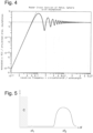
- Fig. 3 gives schematic examples of echo signals detected by transceiver 10. If the frequency of the radar beam 13 is ramped linearly, the frequency difference between outgoing and incoming radar signals is directly representative of the distance between the transceiver 10 and an object which is the source of an echo. Curve A of Fig. 3 is obtained with the sensor operating around f 2 ; at a small frequency difference ⁇ f 1 , just above the leakage range represented by hatched area C, there is the echo from grid 17; at a larger difference ⁇ f 2 , there is an echo from an object, e.g. from the robot 1 itself. When the sensor 6 is operating in the frequency range around f 1 , the radar beam 13 is unaffected by grid 17, and only the object contributes to the radar echo, but not the grid 17, as shown by curve B.
- the radar echo from grid 17 can be limited to a low value which will not overshadow an echo from an outside object, even if this outside object is close to the grid 17, and by appropriately choosing this diameter, the intensity of the radar echo from grid 17 can be set to any desired value.
- the diameter of a metallic sphere is much larger that the radar wavelength, i.e. at a relative frequency of 10 or above, the ratio between radar cross section and projected area of the sphere converges towards unity.
- the diameter is smaller than the wavelength, this ratio is proportional to the fourth power of the frequency.
- the diameter of the wires 15 can be chosen so that although the grid 17 extends across the entire cross section of beam 13, the echo that originates from the grid 17 is only slightly above the detection threshold of transceiver 10.
- the radar sensor 6 can be simplified by dispensing with grid 14. In that case, the echo from the grid 17 is present continuously while the sensor 6 is operating, but this doesn't cause a problem, since this echo is too weak to conceal the echo of an outside object close to the leakage range that should be detected. Quite to the contrary, precisely because the echo from the grid 17 is weak, any malfunction of the sensor 6 is likely to cause it to drop below the detection threshold, whereby the malfunction is detected.
- An example of a typical radar echo signal according to this simplified embodiment is shown in Fig. 5 in a diagram analogous to that of Fig. 3 .
- the transceiver 10 can also be simplified, since there is no more need to switch between different frequency ranges. Since the echo from grid 17 is present whenever the sensor 6 is operating, and not only if it is operating in the frequency range around f 2 , a malfunction of sensor 6 is detected as soon as it occurs.
Landscapes
- Engineering & Computer Science (AREA)
- Radar, Positioning & Navigation (AREA)
- Remote Sensing (AREA)
- Physics & Mathematics (AREA)
- Computer Networks & Wireless Communication (AREA)
- General Physics & Mathematics (AREA)
- Automation & Control Theory (AREA)
- Robotics (AREA)
- Electromagnetism (AREA)
- Radar Systems Or Details Thereof (AREA)
Claims (12)
- Capteur radar (6, 7) comprenant une unité d'émission-réception (10) destinée à émettre un faisceau radar (13) le long d'un trajet de faisceau dans une direction sortante et à recevoir un rayonnement radar le long dudit trajet de faisceau dans une direction entrante, le capteur radar (6, 7) comprenant en outre un objet de référence (15) placé dans ledit trajet de faisceau pour rediriger une partie du faisceau radar sortant (13) dans la direction entrante, l'objet de référence étant l'un d'une pluralité d'objets de référence placés dans le faisceau radar (13), et la taille des objets de référence dans au moins une dimension étant inférieure à la longueur d'onde du faisceau radar (13), la taille de l'au moins un objet de référence dans une seconde dimension orthogonale à ladite première dimension étant supérieure à la longueur d'onde du faisceau radar (13), et chaque objet de référence (15) étant linéaire et ayant des première et seconde extrémités,
caractérisé en ce que,
les première et seconde extrémités des objets de référence sont montées dans un cadre (16), les objets de référence étant disposés selon des premier et second motifs réguliers, le premier motif (14) s'étendant dans un premier plan qui coupe le faisceau, et le second motif (17) s'étendant dans un second plan qui est parallèle au premier plan, l'émetteur-récepteur radar (10) pouvant fonctionner sélectivement à au moins une première et une seconde fréquence (f1, f2), et la distance entre les deux motifs étant égale à la moitié de la distance de Talbot à ladite première fréquence (f1). - Capteur radar selon la revendication 1, dans lequel au moins certains de ladite pluralité d'objets de référence sont situés au-delà d'une distance de fuite de l'unité d'émission-réception (10).
- Capteur radar selon la revendication 1 ou 2, dans lequel la taille de l'objet de référence dans ladite première dimension est inférieure à la moitié de la longueur d'onde, préférablement inférieure à un cinquième de la longueur d'onde, et encore plus préférablement, inférieure à un dixième de la longueur d'onde.
- Capteur radar selon la revendication 1, 2 ou 3, dans lequel l'au moins un objet de référence est monté de manière stationnaire par rapport à l'émetteur-récepteur (10) .
- Capteur radar selon l'une quelconque des revendications précédentes, dans lequel la taille de l'au moins un objet de référence dans la seconde dimension est supérieure à un diamètre du faisceau radar (13).
- Capteur radar selon l'une quelconque des revendications précédentes, dans lequel les objets de référence sont des fils métalliques (15).
- Capteur radar selon l'une quelconque des revendications précédentes, dans lequel une pluralité desdits objets de référence sont distribués sur la section transversale du faisceau radar (13).
- Capteur radar selon la revendication 1, dans lequel les objets de référence sont agencés dans au moins un plan qui coupe le faisceau radar (13).
- Capteur radar selon la revendication 1 ou 7, dans lequel les objets de référence sont agencés selon au moins un motif régulier.
- Capteur radar selon la revendication 1, dans lequel, lorsque l'émetteur-récepteur (10) fonctionne à ladite première fréquence (f1), les objets de référence du second motif régulier sont situés dans des zones sombres d'une grille de Talbot générée par ledit premier motif régulier.
- Capteur radar de la revendication 1 ou 10, dans lequel le premier motif régulier est situé dans une zone de fuite de l'émetteur-récepteur radar (10).
- Robot (1) comprenant au moins un lien (4) qui est relié de manière rotative à une base (2), à un effecteur final (3) ou à un autre lien (4), dans lequel ledit lien (4) est pourvu d'au moins un capteur radar (7) selon l'une quelconque des revendications précédentes.
Applications Claiming Priority (1)
| Application Number | Priority Date | Filing Date | Title |
|---|---|---|---|
| PCT/EP2018/079090 WO2020083474A1 (fr) | 2018-10-24 | 2018-10-24 | Capteur radar et robot utilisant celui-ci |
Publications (2)
| Publication Number | Publication Date |
|---|---|
| EP3871003A1 EP3871003A1 (fr) | 2021-09-01 |
| EP3871003B1 true EP3871003B1 (fr) | 2025-02-26 |
Family
ID=64049190
Family Applications (1)
| Application Number | Title | Priority Date | Filing Date |
|---|---|---|---|
| EP18795454.0A Active EP3871003B1 (fr) | 2018-10-24 | 2018-10-24 | Capteur radar et robot |
Country Status (4)
| Country | Link |
|---|---|
| US (1) | US12025731B2 (fr) |
| EP (1) | EP3871003B1 (fr) |
| CN (1) | CN112867940B (fr) |
| WO (1) | WO2020083474A1 (fr) |
Families Citing this family (5)
| Publication number | Priority date | Publication date | Assignee | Title |
|---|---|---|---|---|
| KR102870513B1 (ko) * | 2019-02-14 | 2025-10-14 | 퍼시몬 테크놀로지스 코포레이션 | 로봇 시스템을 위한 라이다 기반의 위치 측정 |
| CN113850999B (zh) * | 2021-09-03 | 2022-11-25 | 杭州海康威视数字技术股份有限公司 | 车位检测装置和用于监控车位的具有雷达的摄像机装置 |
| US12459123B2 (en) | 2022-02-16 | 2025-11-04 | Mantis Robotics, Inc. | Robot system with object detecting sensors |
| EP4428571A1 (fr) | 2023-03-06 | 2024-09-11 | Universität Ulm | Dispositif et procédé de détection de l'environnement d'au moins un objet ou une partie d'objet |
| US20250339970A1 (en) * | 2024-05-01 | 2025-11-06 | The Boeing Company | System and method for controlling operation of a robot |
Family Cites Families (17)
| Publication number | Priority date | Publication date | Assignee | Title |
|---|---|---|---|---|
| DE3789901T2 (de) * | 1987-01-13 | 1994-12-22 | Thomas Dewitt | Entfernungsmessung mit hilfe von diffraktion. |
| US7202776B2 (en) * | 1997-10-22 | 2007-04-10 | Intelligent Technologies International, Inc. | Method and system for detecting objects external to a vehicle |
| JP4757919B2 (ja) * | 2005-09-27 | 2011-08-24 | コングスベル マリタイム アクティーゼルスカブ | レーダー式液位測定装置用の遮蔽機構 |
| EP1804149B1 (fr) * | 2005-12-28 | 2011-05-18 | ABB Research Ltd. | Robot mobile |
| ATE481653T1 (de) * | 2006-01-29 | 2010-10-15 | Rafael Armament Dev Authority | Ladar mit passivem faser-optischem scanner |
| CN101592783B (zh) * | 2009-06-19 | 2011-01-26 | 中国科学院上海光学精密机械研究所 | 相干阵列激光逆达曼光栅合束孔径装填装置 |
| EP2315311A1 (fr) * | 2009-10-23 | 2011-04-27 | The European Union, represented by the European Commission | Système d'imagerie par radar à bande ultra large utilisant un réseau de transducteurs à entrées et sorties multiples (MIMO) |
| CN102866394A (zh) * | 2012-10-17 | 2013-01-09 | 上海师范大学 | 一种相控阵激光扫描旁瓣抑制装置 |
| DE102013010993A1 (de) | 2013-07-02 | 2015-01-08 | Brose Fahrzeugteile Gmbh & Co. Kommanditgesellschaft, Hallstadt | Objekterfassungsvorrichtung für ein Fahrzeug |
| US9575184B2 (en) * | 2014-07-03 | 2017-02-21 | Continental Advanced Lidar Solutions Us, Inc. | LADAR sensor for a dense environment |
| DE102014017917B3 (de) * | 2014-12-04 | 2015-11-12 | Audi Ag | Verfahren zum Konfigurieren wenigstens eines an einer von mehreren Einbaupositionen in einem Kraftfahrzeug verbauten Radarsensors hinsichtlich der Einbauposition und Kraftfahrzeug |
| WO2016116098A1 (fr) * | 2015-01-22 | 2016-07-28 | Fachhochschule Aachen | Dispositif de mesure et de surveillance de grandeurs liées aux pneumatiques pour un véhicule |
| DE102015004087B3 (de) * | 2015-03-31 | 2016-12-29 | gomtec GmbH | Fahrbarer Roboter mit Kollisionserkennung |
| DE102016125412B4 (de) * | 2015-12-24 | 2023-08-17 | Nidec Elesys Corporation | Schlitz-Array-Antenne und Radar, Radarsystem sowie Drahtlos-Kommunikationssystem mit der Schlitz-Array-Antenne |
| DE102017100780A1 (de) * | 2017-01-17 | 2018-07-19 | Abb Schweiz Ag | Verfahren zur Reduzierung von Messstörungen beim Betrieb eines kollaborierenden Industrieroboters mit einer radarbasierten Kollisionserkennung sowie Industrieroboter zur Durchführung des Verfahrens |
| US10581150B2 (en) * | 2017-04-21 | 2020-03-03 | Rohde & Schwarz Gmbh & Co. Kg | Method and apparatus for radar accuracy measurements |
| DE202017103676U1 (de) * | 2017-06-21 | 2018-09-24 | Sick Ag | Radarvorrichtung zur Erfassung eines Objekts in einem Überwachungsbereich |
-
2018
- 2018-10-24 EP EP18795454.0A patent/EP3871003B1/fr active Active
- 2018-10-24 CN CN201880098978.2A patent/CN112867940B/zh active Active
- 2018-10-24 WO PCT/EP2018/079090 patent/WO2020083474A1/fr not_active Ceased
-
2021
- 2021-04-23 US US17/238,231 patent/US12025731B2/en active Active
Non-Patent Citations (2)
| Title |
|---|
| LEWIS G ET AL: "Bistatic radar scattering experiments of parallel wire grids", IGARSS 2002. IEEE 2002 INTERNATIONAL GEOSCIENCE AND REMOTE SENSING SYMPOSIUM. TORONTO, SWEDEN, JUNE 24 -28, 2002; [IEEE INTERNATIONAL GEOSCIENCE AND REMOTE SENSING SYMPOSIUM], NEW YORK, NY : IEEE, US, vol. 1, 24 June 2002 (2002-06-24), pages 444 - 446, XP010597366, ISBN: 978-0-7803-7536-9 * |
| MISHRA S R ET AL: "PRECISION RADAR CROSS-SECTION MEASUREMENTS FOR COMPUTER CODE VALIDATION", IEEE TRANSACTIONS ON INSTRUMENTATION AND MEASUREMENT, IEEE, USA, vol. 42, no. 2, 1 April 1993 (1993-04-01), pages 179 - 185, XP000387448, ISSN: 0018-9456, DOI: 10.1109/19.278545 * |
Also Published As
| Publication number | Publication date |
|---|---|
| US20210239794A1 (en) | 2021-08-05 |
| EP3871003A1 (fr) | 2021-09-01 |
| CN112867940A (zh) | 2021-05-28 |
| WO2020083474A1 (fr) | 2020-04-30 |
| CN112867940B (zh) | 2023-03-24 |
| US12025731B2 (en) | 2024-07-02 |
Similar Documents
| Publication | Publication Date | Title |
|---|---|---|
| EP3871003B1 (fr) | Capteur radar et robot | |
| US8575538B2 (en) | Safety system for safeguarding a moving, guided motion element that blocks the movement of the guided motion element from triggering the saftey mode | |
| JP2991659B2 (ja) | 小型乗物用の多数のアンテナを含む後方及び側方障害物検出システム | |
| EP2546676B1 (fr) | Système et procédé de détection d'obstructions et mauvais alignement des systèmes radar d'un véhicule terrestre | |
| US11459813B2 (en) | Door opening and closing device | |
| JP6227244B2 (ja) | 侵入検知システム及び侵入検知方法 | |
| US20080158046A1 (en) | Radar device | |
| CN108474852B (zh) | 用于检测激光扫描仪的功能损坏的方法、激光扫描仪和机动车辆 | |
| CN111059454B (zh) | 在移动机器的环境中保护人类的方法 | |
| CN111337940A (zh) | 物体检测器 | |
| EP3276373A1 (fr) | Procédé et système de navigation mobile | |
| US20080252895A1 (en) | Test method for the testing of the functional capability of a monitoring sensor, monitoring method and monitoring sensor | |
| US11385329B2 (en) | Radar sensor and robot using the same | |
| KR19990022145A (ko) | 초음파 영역 감시 시스템 | |
| US6909369B2 (en) | Device for monitoring an area | |
| US20140118170A1 (en) | Vehicle detector | |
| JP2011196938A (ja) | 車載レーダ装置の調整システム | |
| US11519718B2 (en) | Device and method for determining a measurement of a strand-shaped object | |
| US20200391703A1 (en) | Cleaning control device and cleaning control method | |
| CN112305544B (zh) | 具有雷达传感器的机动车和用于运行机动车的方法 | |
| CN117377889A (zh) | 用于识别激光雷达系统的阻断的方法和装置及对应运输工具 | |
| WO2019197034A1 (fr) | Capteur à radar et robot utilisant ce capteur | |
| KR20230147676A (ko) | 오브젝트와 장치 표면 사이의 최소 거리를 결정하기 위한 방법, 장치 표면을 갖는 핸들링 장치용 안전 디바이스, 및 핸들링 장치 | |
| JP2024004838A (ja) | 測位装置およびそれを備えた無人搬送機システム | |
| JP2024039997A (ja) | 距離測定装置及び、距離測定方法 |
Legal Events
| Date | Code | Title | Description |
|---|---|---|---|
| STAA | Information on the status of an ep patent application or granted ep patent |
Free format text: STATUS: UNKNOWN |
|
| STAA | Information on the status of an ep patent application or granted ep patent |
Free format text: STATUS: THE INTERNATIONAL PUBLICATION HAS BEEN MADE |
|
| PUAI | Public reference made under article 153(3) epc to a published international application that has entered the european phase |
Free format text: ORIGINAL CODE: 0009012 |
|
| STAA | Information on the status of an ep patent application or granted ep patent |
Free format text: STATUS: REQUEST FOR EXAMINATION WAS MADE |
|
| 17P | Request for examination filed |
Effective date: 20210521 |
|
| AK | Designated contracting states |
Kind code of ref document: A1 Designated state(s): AL AT BE BG CH CY CZ DE DK EE ES FI FR GB GR HR HU IE IS IT LI LT LU LV MC MK MT NL NO PL PT RO RS SE SI SK SM TR |
|
| DAV | Request for validation of the european patent (deleted) | ||
| DAX | Request for extension of the european patent (deleted) | ||
| STAA | Information on the status of an ep patent application or granted ep patent |
Free format text: STATUS: EXAMINATION IS IN PROGRESS |
|
| 17Q | First examination report despatched |
Effective date: 20240508 |
|
| GRAP | Despatch of communication of intention to grant a patent |
Free format text: ORIGINAL CODE: EPIDOSNIGR1 |
|
| STAA | Information on the status of an ep patent application or granted ep patent |
Free format text: STATUS: GRANT OF PATENT IS INTENDED |
|
| INTG | Intention to grant announced |
Effective date: 20241024 |
|
| GRAS | Grant fee paid |
Free format text: ORIGINAL CODE: EPIDOSNIGR3 |
|
| GRAA | (expected) grant |
Free format text: ORIGINAL CODE: 0009210 |
|
| STAA | Information on the status of an ep patent application or granted ep patent |
Free format text: STATUS: THE PATENT HAS BEEN GRANTED |
|
| AK | Designated contracting states |
Kind code of ref document: B1 Designated state(s): AL AT BE BG CH CY CZ DE DK EE ES FI FR GB GR HR HU IE IS IT LI LT LU LV MC MK MT NL NO PL PT RO RS SE SI SK SM TR |
|
| RAP3 | Party data changed (applicant data changed or rights of an application transferred) |
Owner name: ABB SCHWEIZ AG |
|
| REG | Reference to a national code |
Ref country code: GB Ref legal event code: FG4D |
|
| REG | Reference to a national code |
Ref country code: CH Ref legal event code: EP |
|
| REG | Reference to a national code |
Ref country code: DE Ref legal event code: R096 Ref document number: 602018079631 Country of ref document: DE |
|
| REG | Reference to a national code |
Ref country code: IE Ref legal event code: FG4D |
|
| REG | Reference to a national code |
Ref country code: NL Ref legal event code: MP Effective date: 20250226 |
|
| PG25 | Lapsed in a contracting state [announced via postgrant information from national office to epo] |
Ref country code: RS Free format text: LAPSE BECAUSE OF FAILURE TO SUBMIT A TRANSLATION OF THE DESCRIPTION OR TO PAY THE FEE WITHIN THE PRESCRIBED TIME-LIMIT Effective date: 20250526 |
|
| PG25 | Lapsed in a contracting state [announced via postgrant information from national office to epo] |
Ref country code: FI Free format text: LAPSE BECAUSE OF FAILURE TO SUBMIT A TRANSLATION OF THE DESCRIPTION OR TO PAY THE FEE WITHIN THE PRESCRIBED TIME-LIMIT Effective date: 20250226 |
|
| PG25 | Lapsed in a contracting state [announced via postgrant information from national office to epo] |
Ref country code: PL Free format text: LAPSE BECAUSE OF FAILURE TO SUBMIT A TRANSLATION OF THE DESCRIPTION OR TO PAY THE FEE WITHIN THE PRESCRIBED TIME-LIMIT Effective date: 20250226 |
|
| PG25 | Lapsed in a contracting state [announced via postgrant information from national office to epo] |
Ref country code: ES Free format text: LAPSE BECAUSE OF FAILURE TO SUBMIT A TRANSLATION OF THE DESCRIPTION OR TO PAY THE FEE WITHIN THE PRESCRIBED TIME-LIMIT Effective date: 20250226 |
|
| REG | Reference to a national code |
Ref country code: LT Ref legal event code: MG9D |
|
| PG25 | Lapsed in a contracting state [announced via postgrant information from national office to epo] |
Ref country code: NO Free format text: LAPSE BECAUSE OF FAILURE TO SUBMIT A TRANSLATION OF THE DESCRIPTION OR TO PAY THE FEE WITHIN THE PRESCRIBED TIME-LIMIT Effective date: 20250526 Ref country code: IS Free format text: LAPSE BECAUSE OF FAILURE TO SUBMIT A TRANSLATION OF THE DESCRIPTION OR TO PAY THE FEE WITHIN THE PRESCRIBED TIME-LIMIT Effective date: 20250626 |
|
| PG25 | Lapsed in a contracting state [announced via postgrant information from national office to epo] |
Ref country code: NL Free format text: LAPSE BECAUSE OF FAILURE TO SUBMIT A TRANSLATION OF THE DESCRIPTION OR TO PAY THE FEE WITHIN THE PRESCRIBED TIME-LIMIT Effective date: 20250226 |
|
| PG25 | Lapsed in a contracting state [announced via postgrant information from national office to epo] |
Ref country code: HR Free format text: LAPSE BECAUSE OF FAILURE TO SUBMIT A TRANSLATION OF THE DESCRIPTION OR TO PAY THE FEE WITHIN THE PRESCRIBED TIME-LIMIT Effective date: 20250226 |
|
| PG25 | Lapsed in a contracting state [announced via postgrant information from national office to epo] |
Ref country code: LV Free format text: LAPSE BECAUSE OF FAILURE TO SUBMIT A TRANSLATION OF THE DESCRIPTION OR TO PAY THE FEE WITHIN THE PRESCRIBED TIME-LIMIT Effective date: 20250226 Ref country code: PT Free format text: LAPSE BECAUSE OF FAILURE TO SUBMIT A TRANSLATION OF THE DESCRIPTION OR TO PAY THE FEE WITHIN THE PRESCRIBED TIME-LIMIT Effective date: 20250626 |
|
| PG25 | Lapsed in a contracting state [announced via postgrant information from national office to epo] |
Ref country code: GR Free format text: LAPSE BECAUSE OF FAILURE TO SUBMIT A TRANSLATION OF THE DESCRIPTION OR TO PAY THE FEE WITHIN THE PRESCRIBED TIME-LIMIT Effective date: 20250527 Ref country code: BG Free format text: LAPSE BECAUSE OF FAILURE TO SUBMIT A TRANSLATION OF THE DESCRIPTION OR TO PAY THE FEE WITHIN THE PRESCRIBED TIME-LIMIT Effective date: 20250226 |
|
| REG | Reference to a national code |
Ref country code: AT Ref legal event code: MK05 Ref document number: 1771151 Country of ref document: AT Kind code of ref document: T Effective date: 20250226 |
|
| PG25 | Lapsed in a contracting state [announced via postgrant information from national office to epo] |
Ref country code: SE Free format text: LAPSE BECAUSE OF FAILURE TO SUBMIT A TRANSLATION OF THE DESCRIPTION OR TO PAY THE FEE WITHIN THE PRESCRIBED TIME-LIMIT Effective date: 20250226 |
|
| PG25 | Lapsed in a contracting state [announced via postgrant information from national office to epo] |
Ref country code: SM Free format text: LAPSE BECAUSE OF FAILURE TO SUBMIT A TRANSLATION OF THE DESCRIPTION OR TO PAY THE FEE WITHIN THE PRESCRIBED TIME-LIMIT Effective date: 20250226 |
|
| PG25 | Lapsed in a contracting state [announced via postgrant information from national office to epo] |
Ref country code: DK Free format text: LAPSE BECAUSE OF FAILURE TO SUBMIT A TRANSLATION OF THE DESCRIPTION OR TO PAY THE FEE WITHIN THE PRESCRIBED TIME-LIMIT Effective date: 20250226 |
|
| PG25 | Lapsed in a contracting state [announced via postgrant information from national office to epo] |
Ref country code: IT Free format text: LAPSE BECAUSE OF FAILURE TO SUBMIT A TRANSLATION OF THE DESCRIPTION OR TO PAY THE FEE WITHIN THE PRESCRIBED TIME-LIMIT Effective date: 20250226 |
|
| PG25 | Lapsed in a contracting state [announced via postgrant information from national office to epo] |
Ref country code: AT Free format text: LAPSE BECAUSE OF FAILURE TO SUBMIT A TRANSLATION OF THE DESCRIPTION OR TO PAY THE FEE WITHIN THE PRESCRIBED TIME-LIMIT Effective date: 20250226 |
|
| PG25 | Lapsed in a contracting state [announced via postgrant information from national office to epo] |
Ref country code: EE Free format text: LAPSE BECAUSE OF FAILURE TO SUBMIT A TRANSLATION OF THE DESCRIPTION OR TO PAY THE FEE WITHIN THE PRESCRIBED TIME-LIMIT Effective date: 20250226 Ref country code: CZ Free format text: LAPSE BECAUSE OF FAILURE TO SUBMIT A TRANSLATION OF THE DESCRIPTION OR TO PAY THE FEE WITHIN THE PRESCRIBED TIME-LIMIT Effective date: 20250226 |
|
| PG25 | Lapsed in a contracting state [announced via postgrant information from national office to epo] |
Ref country code: RO Free format text: LAPSE BECAUSE OF FAILURE TO SUBMIT A TRANSLATION OF THE DESCRIPTION OR TO PAY THE FEE WITHIN THE PRESCRIBED TIME-LIMIT Effective date: 20250226 |
|
| PG25 | Lapsed in a contracting state [announced via postgrant information from national office to epo] |
Ref country code: SK Free format text: LAPSE BECAUSE OF FAILURE TO SUBMIT A TRANSLATION OF THE DESCRIPTION OR TO PAY THE FEE WITHIN THE PRESCRIBED TIME-LIMIT Effective date: 20250226 |
|
| REG | Reference to a national code |
Ref country code: DE Ref legal event code: R097 Ref document number: 602018079631 Country of ref document: DE |
|
| PLBE | No opposition filed within time limit |
Free format text: ORIGINAL CODE: 0009261 |
|
| STAA | Information on the status of an ep patent application or granted ep patent |
Free format text: STATUS: NO OPPOSITION FILED WITHIN TIME LIMIT |
|
| PGFP | Annual fee paid to national office [announced via postgrant information from national office to epo] |
Ref country code: DE Payment date: 20251021 Year of fee payment: 8 |
|
| 26N | No opposition filed |
Effective date: 20251127 |