EP3871565A1 - Présentoir d'exposition pour marchandises - Google Patents
Présentoir d'exposition pour marchandises Download PDFInfo
- Publication number
- EP3871565A1 EP3871565A1 EP21156655.9A EP21156655A EP3871565A1 EP 3871565 A1 EP3871565 A1 EP 3871565A1 EP 21156655 A EP21156655 A EP 21156655A EP 3871565 A1 EP3871565 A1 EP 3871565A1
- Authority
- EP
- European Patent Office
- Prior art keywords
- goods
- display stand
- outer layer
- inner layer
- goods carrier
- Prior art date
- Legal status (The legal status is an assumption and is not a legal conclusion. Google has not performed a legal analysis and makes no representation as to the accuracy of the status listed.)
- Granted
Links
Images



Classifications
-
- A—HUMAN NECESSITIES
- A47—FURNITURE; DOMESTIC ARTICLES OR APPLIANCES; COFFEE MILLS; SPICE MILLS; SUCTION CLEANERS IN GENERAL
- A47F—SPECIAL FURNITURE, FITTINGS, OR ACCESSORIES FOR SHOPS, STOREHOUSES, BARS, RESTAURANTS OR THE LIKE; PAYING COUNTERS
- A47F5/00—Show stands, hangers, or shelves characterised by their constructional features
- A47F5/10—Adjustable or foldable or dismountable display stands
- A47F5/11—Adjustable or foldable or dismountable display stands made of cardboard, paper or the like
- A47F5/112—Adjustable or foldable or dismountable display stands made of cardboard, paper or the like hand-folded from sheet material
- A47F5/116—Shelving racks
Definitions
- the present invention relates to a goods display stand comprising a rear wall with side walls articulated on both sides, the side walls being formed at least in an area adjoining vertical outer edges with an outer layer and an inner layer, at least one goods carrier, comprising a base and a multi-layered front wall, wherein the floor extends between the rear wall and side walls.
- Corresponding goods display stands are widespread and are used in particular in retail outlets to present goods.
- the goods display stands are often made of cardboard materials and are only set up on site.
- product display stands are provided, which are pre-assembled and can be transferred into the useful position at the desired installation location with just a few movements.
- the basic structure here comprises two side walls, a rear wall and a compartment connected to the side walls and the rear wall for the presentation of goods.
- connecting structures are formed on the inner sides of the side walls, which on the one hand comprise a recess and on the other hand an engagement surface arranged between an outer layer and an inner layer, the front wall of the compartment cooperating with the recess and the side edges of the compartment rest on the peripheral edge of the recess.
- folding strips are provided which engage the engagement surfaces of the connecting structures.
- the object of the present invention is to provide a merchandise display stand which can be manufactured in a material-saving and inexpensive manner and which ensures a light and effective construction which, in particular, can be carried out by only one person.
- a product display stand comprising a rear wall with side walls articulated on both sides, the side walls being formed at least in an area adjoining vertical outer edges with an outer layer and an inner layer, at least one goods carrier, comprising a base and a multi-layered front wall, whereby the base extends between the rear wall and side walls, solved in that a fixing tab is punched out of each side wall, which extends over a portion of the outer layer and a portion of the inner layer, the free The end is punched out of the inner layer and the fixed end is pivotably applied to the outer layer of the side wall, wherein in the state of use at least the part punched out of the inner layer is inserted into the front wall of the goods carrier.
- the connection between the goods carrier and side walls is thus achieved via a fixing tab which fixes the goods carrier in its position and at the same time holds the side walls in the desired position.
- the fixing tab can simply be inserted from the outside and thus significantly facilitates the setting up of the goods display stand according to the invention. Since the fixing tab is also punched out of the outer layer and the inner layer, the connection according to the invention can be produced in one piece with the side walls and is therefore particularly material-saving. The goods display stand according to the invention can thus be produced particularly inexpensively.
- recesses are formed in the area of the fixing tabs on the vertical outer edges of the side walls, which extend over the outer layer and the inner layer and can be brought into engagement with the goods carrier.
- the recesses provide an additional connection option with the goods carrier, which also contributes to the stability of the goods display stand. Since the recesses are arranged in the area of the vertical outer edges, particularly easy access to them is possible here, so that no complicated hand movements are necessary to bring the goods carrier into engagement with the recesses. Furthermore, by providing the recesses in the area of the outer edge, it is possible for the actual usable area of the goods carrier to extend over the entire space enclosed by the side walls and the rear wall. This also ensures particularly good access to the products arranged on the goods carrier.
- the front wall of the goods carrier can preferably have lateral end sections on both sides which extend beyond the side edge of the base, the end sections being engageable with the recesses in the state of use. The end sections can then simply be inserted into the recesses and rest on the lower edge of the recess.
- a hollow profile for receiving the fixing tabs is formed in the area of the end sections of the front wall of the goods carrier.
- a corresponding hollow profile makes it easier to insert the fixing tab, so that assembly is correspondingly simplified. This also makes that Folding the goods display stand from the position of use into the transport position is facilitated.
- the front wall of the goods carrier is designed in three layers, comprising an outer layer, an intermediate layer and an inner layer, the intermediate layer only extending over a predetermined section.
- the hollow profile can be provided in the region of the end sections in a simple manner without the need to set the distance between the outer layer and the inner layer in a complex manner.
- This embodiment also enables a one-piece design of the goods carrier.
- the outer layer of the front wall can extend flush to the outside of the outer layer of the side wall and the inner layer of the front wall can extend at most to the inside of the outer layer of the side wall.
- the lateral end surfaces of the outer layer are flush with the exterior of the side walls, so that a uniform appearance is achieved. Since the fixing tab into which the H the hollow profile profile engages between the outer and inner layer, the set-back inner layer has the same effect that the fixing tab can be arranged flush in a plane with the outer installation of the side wall. In this way, a uniform side wall can be guaranteed and a visually appealing goods display stand can be provided.
- each side wall adjoining the outer edge is arranged at a predetermined distance from one another, so that a cavity is also created in the area of the side wall.
- This cavity can be retained over the entire width of the side wall, or it can decrease, so that the outer layer and the inner layer are arranged one on top of the other in an area adjoining the rear wall.
- the stability of the product display stand can be increased through the cavity provided in the side wall.
- receiving recesses are formed in the area of the inner layer of the side walls, which can be brought into engagement with the goods carrier.
- Corresponding receiving recesses can provide an additional fixation of the goods carrier in the area of the side wall. The additional fixation increases the load-bearing capacity of the goods carrier, so that the stability of the goods display stand is improved.
- the side edges of the bottom of the goods carrier rest on support edges formed in the region of the receiving recesses.
- the side edges can, for example, be configured in sections with projections which then rest on the support edges.
- a corresponding design of the goods carrier is particularly simple both in production and in construction.
- the product carrier is designed on the side edges of the base with downwardly extending support tabs which, when in use, extend into the receiving recesses of the side walls.
- the support tabs are folded away from the floor during the transfer into the position of use and inserted into the receiving recesses until the floor rests on the support edge.
- a cavity is formed between the outer installation and the inner layer, since this considerably simplifies the introduction of the support bracket.
- the side walls are also fixed in their position by the support straps and the stability of the goods carrier is increased at the same time.
- Another preferred embodiment can provide that the goods carrier is connected in an articulated manner to the rear wall via a rear flap arranged parallel to the rear wall.
- a corresponding back flap can be connected in one piece to the goods carrier or provided as a separate element. Thanks to the articulated back flap, which is connected to the rear wall, it is possible to pre-assemble the goods carrier on the rear wall so that it only has to be folded into the operational state on site.
- the front wall is arranged in an articulated manner on the bottom of the goods carrier. Due to the articulated front wall, it is possible not only to arrange the carrier structure made up of side walls and rear wall but also the goods carrier in a flat position so that the goods display stand can be folded up to save space in the transport position.
- the goods carrier is formed in one piece.
- the goods carrier can be transferred into the built-up position in just a few simple steps.
- the support structure is also made in one piece from side walls and rear wall.
- the two elements of the product display stand can be glued to one another or connected in another known manner. If the goods carriers are not glued to the rear wall, it is possible to remove individual goods carriers on site if a larger area is required between two goods carriers.
- a further preferred embodiment can provide that the goods display stand can be transferred from an essentially flat folded transport and storage position into an unfolded state of use. This ensures that the product display stand takes up as little space as possible in the storage position and can be converted into the use position with just a few movements.
- the pre-assembly of the goods carriers on the rear wall contributes in particular to this.
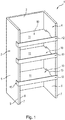
- FIG. 1 an inventive goods display stand 1 is shown in the position of use.
- the goods display stand 1 comprises a support structure consisting of a rear wall 2, a first side wall 3 and a second side wall 4 opposite these .
- Each side wall 3, 4 is double-walled and comprises an outer layer 5 directly adjoining the rear wall 2, as well as an inner layer 6 connected to the outer layer 5 via a vertical outer edge 7 brought, and forms the inside of the support structure.
- the vertical outer edge 7 is formed by two fold lines 8, 9 arranged parallel to one another. The distance between the two fold lines 8, 9 can be selected so that the outer layer 5 and inner layer 6 are initially arranged at a predetermined distance so that a cavity is formed between the outer layer and the inner layer.
- a plurality of product carriers 10 are arranged one above the other in the carrier structure and extend between the two side walls 3, 4 and the rear wall as far as the vertical outer edges 7.
- Each product carrier 10 has a bottom 11 and a front wall 12, and is used to hold products that are offered in their product display stands.
- the front wall 12 extends vertically upwards from the base 11 and thus forms a stop surface for the products arranged thereon. The front wall 12 consequently ensures that the products are held securely.
- the bottom can consist of a single layer of material or be reinforced.
- the goods carrier 10 rotated in the carrier structure, i.e. in this case the front wall 12 extends vertically downward from the base 11.
- This embodiment has the advantage that direct access to the goods is possible so that they can be easily removed.
- products that are still in an outer packaging can be arranged on a correspondingly arranged goods carrier 10, so that the outer packaging on the one hand identifies the contained products more precisely and, on the other hand, the products are held by the outer packaging.
- the outer packaging can be cardboard boxes, cardboard sections, etc., for example.
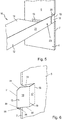
- a side wall is shown in sections with a view from the inside and a view from the outside.
- the opposite side wall is designed as a mirror image of this.
- a receiving recess 13 is formed on the inside of the side wall in the area of the inner layer 6, which has an essentially rectangular shape, the short edges of the rectangle being arranged parallel to the outer edge 7 and the long edges perpendicular to it .
- the lower edge 14 of the receiving recess 13 forms a support edge which, as will be described below, can be brought into engagement with a support tab of the goods carrier 10.
- the inner layer 6 and the outer layer 5 can be spaced apart from one another, so that a corresponding support tab can be inserted between the two layers without any problems.
- a distance of one layer between the two layers has proven to be preferred.
- the corresponding distance can be set here by the width of the outer edge 7.
- an intermediate layer could also be introduced between the inner layer and the outer layer, at least in sections, which contributes to the additional stability of the support structure and adjusts the distance between the outer layer and the inner layer.
- each side wall has a fixing tab 15, comprising a fixed end 17 pivoted to the outer layer 5 via a folding edge 16, as well as a free end 18.
- the fixed end 17 and the free end 18 are connected to one another via a folding edge 19 which they can be angled relative to one another.
- the kink edge 19 is here arranged parallel to the fold edge 16.
- the fixing tab 15 interrupts the vertical outer edge 17, ie is punched out of the material of the outer layer and the inner layer in such a way that the vertical outer edge 7 has a recess in this area.
- the fixing tab interrupts the vertical outer edge, ie the folding edges 8, 9 are interrupted in the region of the fixing tab.
- the kink line 19 between the free end 18 and the fixed end is formed parallel to the folded edges 8, 9 in the area of the outer layer 5. If the free end 18 is angled at an angle of 90 ° to the fixed end 17, the fixed end being arranged flush with the outer layer 5, the free end 18 consequently extends in the recess 20 and is offset inward the outer edge 7 is arranged.
- the kink edge 19 can also be formed in the region of the fold edge 9, that is to say as part of the fold edge formed between the outer layer 5 and the vertical outer edge 7.
- the free end 18 of the fixing tab 15 is inserted into the front wall 12 of the goods carrier 10 and thus fixes the goods carrier in the desired position.
- FIG. 4a-c and 5 Various details of the goods carrier are in the Figures 4a-c and 5 shown, these representations aiming in particular at the formation of the front wall 12.
- the Figures 4b the front wall also in section, parallel to a side edge 24 of the bottom 11, so that the individual layers of the front wall become clear.
- the goods carrier is in Figure 4c shown in top view. It is noted that the Figures 4b and 4c serve only for better understanding and are not shown to scale.
- the front wall 12 is also formed in several layers and comprises an outer layer 21, an inner layer 22 and an intermediate layer 36.
- the outer layer 21 corresponds to the front of the goods carrier.
- the outer layer 21 directly adjoins the bottom 11, and is angled therefrom over a kinked edge.
- the inner layer 22 is arranged perpendicular to the outer layer 21 and is also angled therefrom.
- the intermediate layer (not shown) is connected to the inner layer 22 and is arranged between the outer layer 21 and the inner layer 22.
- the individual layers 21, 22 of the front wall 12 are designed to be of different lengths in relation to the distance between the side walls 3, 4 in order to form end sections 23.
- the end sections 23 of the front wall 12 extend here on both sides beyond the side edges 24 of the bottom 11 and include the outer layer 21 and the inner layer 22 as well as a hollow profile 24 formed between them Area of the end sections 23.
- the dimensions of the hollow profile 24 can be selected as required by a suitable design of the intermediate layer.
- the inner layer 22 is made shorter in the area of the end sections 23 than the outer layer 21.
- the end sections 23 are connected to the side walls 3, 4 in such a way that the end sections 23 are arranged in the region of the recesses 20.
- the outer layer 21 extends over the full width of the recess, that is, on both sides up to the outer layer 5, and ends flush with this.
- the inner layer 22, on the other hand, is supported only on the inner layer 6 of the side walls.
- the fixing tab 15 is then angled outwards and the free end 18 is inserted into the hollow profile 24 between the inner layer 22 and the outer layer 21. Since the inner layer 22 is made shorter, the fixing tab 15 is arranged flush with the outer layer 5 in the use position.
- a latching projection can be formed in the area of the fixing tab 15 for the additional fixation of the goods carrier 10 on the carrier structure.
- a correspondingly modified fixing tab is in Figure 6 shown.
- Figure 6 essentially corresponds to the representation in Figure 3 so that only the differences between the two figures will be discussed here.
- the latching projection 30 is formed on the free end 18 of the fixing tab 15.
- the locking projection 30 is arranged on a lower edge 32 of the free end 18, i.e. the edge running perpendicular to the vertical outer edge 7, and adjoins the free outer edge 31.
- the shape of the locking projection 30 can be selected as desired, as long as it is possible to lock it into place.
- the locking projection 30 is designed as an element tapering in the direction of the free outer edge 31 with an inclined outer edge 35 and a holding edge 36 arranged perpendicular to the upper edge 32 of the free end.
- the inclined outer edge enables easy insertion into a latching opening, and the retaining edge 36 then secures the latching projection within the latching opening.
- a corresponding latching opening is provided in the area of the base 11, that is to say adjacent to the outer layer 21, and is designed as a passage opening or slot.
- a corresponding latching projection can also be arranged both on the lower edge 32 of the free end 18 and on an upper edge 33 formed parallel thereto.
- the additional attachment is provided independently of the orientation of the product carrier 10, i.e. the arrangement of the front wall 12.
- the free end 18 can, however, instead of having two locking projections 30, also have a locking projection 30 and a beveled corner 34 connecting the free edge 31 and the upper edge 33 to one another.
- the goods carrier 11 can be provided on its edge opposite the front wall 12 with a fastening strap, which is not shown, via which the goods carrier 11 can be connected to the rear wall.
- the fastening tab can be formed in one piece with the goods carrier or can be fastened to this via known connecting means.
- the connecting means can be detachable or non-detachable as required. Gluing, riveting or a plug connection are mentioned merely as examples.
- the goods carrier 11 can be connected in advance to the carrier structure via this fastening strap, so that the goods display stand according to the invention is transported partially preassembled.
- a corresponding connection is achieved using known connecting means.
- the connection can be detachable or non-detachable, a detachable connection making it possible to adapt the arrangement of the goods carriers on site, if necessary. Adhesives, rivets, etc. are mentioned as possible connecting means only by way of example.
- the fastening tab arranged on the goods carrier 10 can also be inserted into a receiving opening which is formed in the area of the rear wall in order to achieve a corresponding connection here.
- the rear wall is designed with plug-in tabs which cooperate with the fastening tabs of the goods carriers in order to hang the goods carriers.
- the goods carrier is preferably designed with a receiving tab into which the plug-in tab of the rear wall is inserted.
- This receiving tab can, for example, only be formed by the fastening tab or the fastening tab in combination with a rear wall of the goods carrier.
- the receiving tab is open at the bottom and closed at the top.
- the merchandise display stand according to the invention is preferably in a flat lying position, as in FIG Figure 7 shown, transported, the side walls 3, 4 and the rear wall 2 lie in one plane, and the goods carriers are already connected to the rear wall 2, and also lie flat on the rear wall.
- the front wall 12 is designed in such a way that it can also be transferred from the position of use into a lying flat position and is arranged parallel to the bottom 11 of the goods carrier 10.
- the side walls 3, 4 are first angled to the rear wall 2 and the individual goods carriers 10 from the storage position into a substantially perpendicular position to the Rear wall 2 transferred.
- the support tabs are already inserted into the receiving recesses in the area of the side walls 3, 4, so that they lie between the outer layer 5 and the inner layer 6 of the side walls.
- the base 11 rests in sections on the support edges 14 formed by the receiving recesses.
- the side edges of the goods carrier 10 in the sections facing the receiving recesses 13 of the side walls 3, 4 can be formed with projections which correspond approximately to the thickness of the inner layer 6. Since the bottom lies on the support edge and the tabs are inserted between the outer layer and the inner layer, the bottom and the side walls are fixed firmly in the 90 ° position to one another.
- the front wall 12 is folded into a vertical position when the goods carrier is transferred into the state of use, so that it is arranged perpendicular to the rear wall 2.
- the end sections 23 of the front wall are then inserted into the recesses 20 so that the front wall is fixed within the side walls.
- the outer layer of the front wall is flush with the vertical outer edges 7 of the side walls.
- the fixing tabs 15 formed in the area of the side walls are first angled completely from the side wall 3, 4. Then the free end 18 is angled from the fixed end 17 and the free end 18 is inserted into the hollow profile 24 between the outer layer 21 and the inner layer 22 of the front wall 12.
- the goods display stand according to the invention can be transported and stored in a space-saving manner, can be easily built up in a stable manner and manufactured in a material-saving manner.
Landscapes
- Display Racks (AREA)
Applications Claiming Priority (1)
| Application Number | Priority Date | Filing Date | Title |
|---|---|---|---|
| DE102020104995.1A DE102020104995A1 (de) | 2020-02-26 | 2020-02-26 | Warendisplayständer |
Publications (2)
| Publication Number | Publication Date |
|---|---|
| EP3871565A1 true EP3871565A1 (fr) | 2021-09-01 |
| EP3871565B1 EP3871565B1 (fr) | 2022-10-19 |
Family
ID=74591912
Family Applications (1)
| Application Number | Title | Priority Date | Filing Date |
|---|---|---|---|
| EP21156655.9A Active EP3871565B1 (fr) | 2020-02-26 | 2021-02-11 | Présentoir d'exposition pour marchandises |
Country Status (2)
| Country | Link |
|---|---|
| EP (1) | EP3871565B1 (fr) |
| DE (1) | DE102020104995A1 (fr) |
Citations (5)
| Publication number | Priority date | Publication date | Assignee | Title |
|---|---|---|---|---|
| EP0868873A1 (fr) * | 1997-04-04 | 1998-10-07 | Scanilec B.V. | Dispositif pour la présentation d'objets |
| JP3092194U (ja) * | 2002-08-20 | 2003-02-28 | コア株式会社 | 厚紙製組立棚 |
| DE202008017214U1 (de) * | 2008-12-23 | 2010-05-12 | Stange, Hans-Peter | Regal |
| US9474389B2 (en) * | 2012-02-20 | 2016-10-25 | Menasha Corporation | Corrugated hutch |
| EP3205240A2 (fr) | 2016-01-22 | 2017-08-16 | Pozo Negro Beheer B.V. | Structure de base pour un présentoir, présentoir et procédé d'ériger lequel |
Family Cites Families (1)
| Publication number | Priority date | Publication date | Assignee | Title |
|---|---|---|---|---|
| DE29514747U1 (de) | 1995-09-14 | 1996-10-10 | Beiersdorf Ag, 20253 Hamburg | Verkaufsaussteller |
-
2020
- 2020-02-26 DE DE102020104995.1A patent/DE102020104995A1/de not_active Withdrawn
-
2021
- 2021-02-11 EP EP21156655.9A patent/EP3871565B1/fr active Active
Patent Citations (5)
| Publication number | Priority date | Publication date | Assignee | Title |
|---|---|---|---|---|
| EP0868873A1 (fr) * | 1997-04-04 | 1998-10-07 | Scanilec B.V. | Dispositif pour la présentation d'objets |
| JP3092194U (ja) * | 2002-08-20 | 2003-02-28 | コア株式会社 | 厚紙製組立棚 |
| DE202008017214U1 (de) * | 2008-12-23 | 2010-05-12 | Stange, Hans-Peter | Regal |
| US9474389B2 (en) * | 2012-02-20 | 2016-10-25 | Menasha Corporation | Corrugated hutch |
| EP3205240A2 (fr) | 2016-01-22 | 2017-08-16 | Pozo Negro Beheer B.V. | Structure de base pour un présentoir, présentoir et procédé d'ériger lequel |
Also Published As
| Publication number | Publication date |
|---|---|
| EP3871565B1 (fr) | 2022-10-19 |
| DE102020104995A1 (de) | 2021-08-26 |
Similar Documents
| Publication | Publication Date | Title |
|---|---|---|
| DE102007055301B4 (de) | Regaldisplay | |
| DE202017103936U1 (de) | Regalstütze, Regalstützenanordnung, Regalsystem und Aufstellraum für ein Regalsystem | |
| EP2430947B1 (fr) | Présentoir doté d'un intervalle de tablette réduit | |
| DE102008023619B4 (de) | Regaldisplay | |
| EP2422658B1 (fr) | Plateau autodéployant et présentoir autodéployant comprenant de tels plateaux | |
| EP3420857B1 (fr) | Chambre froide comprenant un système d'etagères | |
| DE3441500C2 (de) | Regalboden aus Schichtwerkstoff, insbesondere Metallblech | |
| DE102013001415B4 (de) | Regal aus einem knickbaren flächigen Material wie Pappe oder Wellpappe | |
| EP3871565B1 (fr) | Présentoir d'exposition pour marchandises | |
| DE102009019543B3 (de) | Modulares mehrstöckiges Warendisplay | |
| DE202014102900U1 (de) | Trayregal | |
| DE102019122722B3 (de) | Display | |
| DE69833173T2 (de) | Zusammenstellungsweise von Halterungen, Verkaufsständern oder Verpackungen | |
| EP2526838B1 (fr) | Etagère en materiau plat et pliable | |
| DE2949019C2 (de) | Transportabler Verkaufsanhänger | |
| DE10140931A1 (de) | Stapelbarer Behälter | |
| DE102019208796B4 (de) | Verbindungsmechanismus und möbelstück aus pappe | |
| DE10131736C2 (de) | Fahrzeuginnenverkleidung | |
| CH512367A (de) | Bodenabstützbalken für Transport-Palette | |
| DE2658107A1 (de) | Rolladen | |
| DE9414856U1 (de) | Warenträger | |
| DE2160366A1 (de) | Halterung fuer an eine sichtwand anbringbare haken, kaesten, halter, fachboeden od.dgl | |
| DE102015210214A1 (de) | Pappregal | |
| DE202004012933U1 (de) | Verpackung für mindestens eine Glasscheibe | |
| DE2526898A1 (de) | Regal |
Legal Events
| Date | Code | Title | Description |
|---|---|---|---|
| PUAI | Public reference made under article 153(3) epc to a published international application that has entered the european phase |
Free format text: ORIGINAL CODE: 0009012 |
|
| STAA | Information on the status of an ep patent application or granted ep patent |
Free format text: STATUS: THE APPLICATION HAS BEEN PUBLISHED |
|
| AK | Designated contracting states |
Kind code of ref document: A1 Designated state(s): AL AT BE BG CH CY CZ DE DK EE ES FI FR GB GR HR HU IE IS IT LI LT LU LV MC MK MT NL NO PL PT RO RS SE SI SK SM TR |
|
| STAA | Information on the status of an ep patent application or granted ep patent |
Free format text: STATUS: REQUEST FOR EXAMINATION WAS MADE |
|
| 17P | Request for examination filed |
Effective date: 20211118 |
|
| RBV | Designated contracting states (corrected) |
Designated state(s): AL AT BE BG CH CY CZ DE DK EE ES FI FR GB GR HR HU IE IS IT LI LT LU LV MC MK MT NL NO PL PT RO RS SE SI SK SM TR |
|
| GRAP | Despatch of communication of intention to grant a patent |
Free format text: ORIGINAL CODE: EPIDOSNIGR1 |
|
| STAA | Information on the status of an ep patent application or granted ep patent |
Free format text: STATUS: GRANT OF PATENT IS INTENDED |
|
| INTG | Intention to grant announced |
Effective date: 20220608 |
|
| GRAS | Grant fee paid |
Free format text: ORIGINAL CODE: EPIDOSNIGR3 |
|
| GRAA | (expected) grant |
Free format text: ORIGINAL CODE: 0009210 |
|
| STAA | Information on the status of an ep patent application or granted ep patent |
Free format text: STATUS: THE PATENT HAS BEEN GRANTED |
|
| AK | Designated contracting states |
Kind code of ref document: B1 Designated state(s): AL AT BE BG CH CY CZ DE DK EE ES FI FR GB GR HR HU IE IS IT LI LT LU LV MC MK MT NL NO PL PT RO RS SE SI SK SM TR |
|
| REG | Reference to a national code |
Ref country code: GB Ref legal event code: FG4D Free format text: NOT ENGLISH |
|
| REG | Reference to a national code |
Ref country code: CH Ref legal event code: EP |
|
| REG | Reference to a national code |
Ref country code: DE Ref legal event code: R096 Ref document number: 502021000195 Country of ref document: DE |
|
| REG | Reference to a national code |
Ref country code: IE Ref legal event code: FG4D Free format text: LANGUAGE OF EP DOCUMENT: GERMAN |
|
| REG | Reference to a national code |
Ref country code: AT Ref legal event code: REF Ref document number: 1525023 Country of ref document: AT Kind code of ref document: T Effective date: 20221115 |
|
| REG | Reference to a national code |
Ref country code: NL Ref legal event code: FP |
|
| REG | Reference to a national code |
Ref country code: LT Ref legal event code: MG9D |
|
| PG25 | Lapsed in a contracting state [announced via postgrant information from national office to epo] |
Ref country code: SE Free format text: LAPSE BECAUSE OF FAILURE TO SUBMIT A TRANSLATION OF THE DESCRIPTION OR TO PAY THE FEE WITHIN THE PRESCRIBED TIME-LIMIT Effective date: 20221019 Ref country code: PT Free format text: LAPSE BECAUSE OF FAILURE TO SUBMIT A TRANSLATION OF THE DESCRIPTION OR TO PAY THE FEE WITHIN THE PRESCRIBED TIME-LIMIT Effective date: 20230220 Ref country code: NO Free format text: LAPSE BECAUSE OF FAILURE TO SUBMIT A TRANSLATION OF THE DESCRIPTION OR TO PAY THE FEE WITHIN THE PRESCRIBED TIME-LIMIT Effective date: 20230119 Ref country code: LT Free format text: LAPSE BECAUSE OF FAILURE TO SUBMIT A TRANSLATION OF THE DESCRIPTION OR TO PAY THE FEE WITHIN THE PRESCRIBED TIME-LIMIT Effective date: 20221019 Ref country code: FI Free format text: LAPSE BECAUSE OF FAILURE TO SUBMIT A TRANSLATION OF THE DESCRIPTION OR TO PAY THE FEE WITHIN THE PRESCRIBED TIME-LIMIT Effective date: 20221019 Ref country code: ES Free format text: LAPSE BECAUSE OF FAILURE TO SUBMIT A TRANSLATION OF THE DESCRIPTION OR TO PAY THE FEE WITHIN THE PRESCRIBED TIME-LIMIT Effective date: 20221019 |
|
| PG25 | Lapsed in a contracting state [announced via postgrant information from national office to epo] |
Ref country code: RS Free format text: LAPSE BECAUSE OF FAILURE TO SUBMIT A TRANSLATION OF THE DESCRIPTION OR TO PAY THE FEE WITHIN THE PRESCRIBED TIME-LIMIT Effective date: 20221019 Ref country code: PL Free format text: LAPSE BECAUSE OF FAILURE TO SUBMIT A TRANSLATION OF THE DESCRIPTION OR TO PAY THE FEE WITHIN THE PRESCRIBED TIME-LIMIT Effective date: 20221019 Ref country code: LV Free format text: LAPSE BECAUSE OF FAILURE TO SUBMIT A TRANSLATION OF THE DESCRIPTION OR TO PAY THE FEE WITHIN THE PRESCRIBED TIME-LIMIT Effective date: 20221019 Ref country code: IS Free format text: LAPSE BECAUSE OF FAILURE TO SUBMIT A TRANSLATION OF THE DESCRIPTION OR TO PAY THE FEE WITHIN THE PRESCRIBED TIME-LIMIT Effective date: 20230219 Ref country code: HR Free format text: LAPSE BECAUSE OF FAILURE TO SUBMIT A TRANSLATION OF THE DESCRIPTION OR TO PAY THE FEE WITHIN THE PRESCRIBED TIME-LIMIT Effective date: 20221019 Ref country code: GR Free format text: LAPSE BECAUSE OF FAILURE TO SUBMIT A TRANSLATION OF THE DESCRIPTION OR TO PAY THE FEE WITHIN THE PRESCRIBED TIME-LIMIT Effective date: 20230120 |
|
| REG | Reference to a national code |
Ref country code: DE Ref legal event code: R097 Ref document number: 502021000195 Country of ref document: DE |
|
| PG25 | Lapsed in a contracting state [announced via postgrant information from national office to epo] |
Ref country code: SM Free format text: LAPSE BECAUSE OF FAILURE TO SUBMIT A TRANSLATION OF THE DESCRIPTION OR TO PAY THE FEE WITHIN THE PRESCRIBED TIME-LIMIT Effective date: 20221019 Ref country code: RO Free format text: LAPSE BECAUSE OF FAILURE TO SUBMIT A TRANSLATION OF THE DESCRIPTION OR TO PAY THE FEE WITHIN THE PRESCRIBED TIME-LIMIT Effective date: 20221019 Ref country code: EE Free format text: LAPSE BECAUSE OF FAILURE TO SUBMIT A TRANSLATION OF THE DESCRIPTION OR TO PAY THE FEE WITHIN THE PRESCRIBED TIME-LIMIT Effective date: 20221019 Ref country code: DK Free format text: LAPSE BECAUSE OF FAILURE TO SUBMIT A TRANSLATION OF THE DESCRIPTION OR TO PAY THE FEE WITHIN THE PRESCRIBED TIME-LIMIT Effective date: 20221019 Ref country code: CZ Free format text: LAPSE BECAUSE OF FAILURE TO SUBMIT A TRANSLATION OF THE DESCRIPTION OR TO PAY THE FEE WITHIN THE PRESCRIBED TIME-LIMIT Effective date: 20221019 |
|
| PLBE | No opposition filed within time limit |
Free format text: ORIGINAL CODE: 0009261 |
|
| STAA | Information on the status of an ep patent application or granted ep patent |
Free format text: STATUS: NO OPPOSITION FILED WITHIN TIME LIMIT |
|
| PG25 | Lapsed in a contracting state [announced via postgrant information from national office to epo] |
Ref country code: SK Free format text: LAPSE BECAUSE OF FAILURE TO SUBMIT A TRANSLATION OF THE DESCRIPTION OR TO PAY THE FEE WITHIN THE PRESCRIBED TIME-LIMIT Effective date: 20221019 Ref country code: AL Free format text: LAPSE BECAUSE OF FAILURE TO SUBMIT A TRANSLATION OF THE DESCRIPTION OR TO PAY THE FEE WITHIN THE PRESCRIBED TIME-LIMIT Effective date: 20221019 |
|
| 26N | No opposition filed |
Effective date: 20230720 |
|
| PG25 | Lapsed in a contracting state [announced via postgrant information from national office to epo] |
Ref country code: MC Free format text: LAPSE BECAUSE OF FAILURE TO SUBMIT A TRANSLATION OF THE DESCRIPTION OR TO PAY THE FEE WITHIN THE PRESCRIBED TIME-LIMIT Effective date: 20221019 |
|
| REG | Reference to a national code |
Ref country code: BE Ref legal event code: MM Effective date: 20230228 |
|
| PG25 | Lapsed in a contracting state [announced via postgrant information from national office to epo] |
Ref country code: LU Free format text: LAPSE BECAUSE OF NON-PAYMENT OF DUE FEES Effective date: 20230211 |
|
| PG25 | Lapsed in a contracting state [announced via postgrant information from national office to epo] |
Ref country code: SI Free format text: LAPSE BECAUSE OF FAILURE TO SUBMIT A TRANSLATION OF THE DESCRIPTION OR TO PAY THE FEE WITHIN THE PRESCRIBED TIME-LIMIT Effective date: 20221019 |
|
| REG | Reference to a national code |
Ref country code: IE Ref legal event code: MM4A |
|
| PG25 | Lapsed in a contracting state [announced via postgrant information from national office to epo] |
Ref country code: IE Free format text: LAPSE BECAUSE OF NON-PAYMENT OF DUE FEES Effective date: 20230211 |
|
| PG25 | Lapsed in a contracting state [announced via postgrant information from national office to epo] |
Ref country code: BE Free format text: LAPSE BECAUSE OF NON-PAYMENT OF DUE FEES Effective date: 20230228 |
|
| PG25 | Lapsed in a contracting state [announced via postgrant information from national office to epo] |
Ref country code: IT Free format text: LAPSE BECAUSE OF FAILURE TO SUBMIT A TRANSLATION OF THE DESCRIPTION OR TO PAY THE FEE WITHIN THE PRESCRIBED TIME-LIMIT Effective date: 20221019 |
|
| PG25 | Lapsed in a contracting state [announced via postgrant information from national office to epo] |
Ref country code: BG Free format text: LAPSE BECAUSE OF FAILURE TO SUBMIT A TRANSLATION OF THE DESCRIPTION OR TO PAY THE FEE WITHIN THE PRESCRIBED TIME-LIMIT Effective date: 20221019 |
|
| PG25 | Lapsed in a contracting state [announced via postgrant information from national office to epo] |
Ref country code: BG Free format text: LAPSE BECAUSE OF FAILURE TO SUBMIT A TRANSLATION OF THE DESCRIPTION OR TO PAY THE FEE WITHIN THE PRESCRIBED TIME-LIMIT Effective date: 20221019 |
|
| PG25 | Lapsed in a contracting state [announced via postgrant information from national office to epo] |
Ref country code: CY Free format text: LAPSE BECAUSE OF FAILURE TO SUBMIT A TRANSLATION OF THE DESCRIPTION OR TO PAY THE FEE WITHIN THE PRESCRIBED TIME-LIMIT; INVALID AB INITIO Effective date: 20210211 |
|
| PG25 | Lapsed in a contracting state [announced via postgrant information from national office to epo] |
Ref country code: HU Free format text: LAPSE BECAUSE OF FAILURE TO SUBMIT A TRANSLATION OF THE DESCRIPTION OR TO PAY THE FEE WITHIN THE PRESCRIBED TIME-LIMIT; INVALID AB INITIO Effective date: 20210211 |
|
| GBPC | Gb: european patent ceased through non-payment of renewal fee |
Effective date: 20250211 |
|
| PG25 | Lapsed in a contracting state [announced via postgrant information from national office to epo] |
Ref country code: TR Free format text: LAPSE BECAUSE OF FAILURE TO SUBMIT A TRANSLATION OF THE DESCRIPTION OR TO PAY THE FEE WITHIN THE PRESCRIBED TIME-LIMIT Effective date: 20221019 |
|
| PG25 | Lapsed in a contracting state [announced via postgrant information from national office to epo] |
Ref country code: GB Free format text: LAPSE BECAUSE OF NON-PAYMENT OF DUE FEES Effective date: 20250211 |
|
| REG | Reference to a national code |
Ref country code: CH Ref legal event code: U11 Free format text: ST27 STATUS EVENT CODE: U-0-0-U10-U11 (AS PROVIDED BY THE NATIONAL OFFICE) Effective date: 20260301 |
|
| PGFP | Annual fee paid to national office [announced via postgrant information from national office to epo] |
Ref country code: NL Payment date: 20260228 Year of fee payment: 6 |
|
| PGFP | Annual fee paid to national office [announced via postgrant information from national office to epo] |
Ref country code: DE Payment date: 20260218 Year of fee payment: 6 |
|
| PGFP | Annual fee paid to national office [announced via postgrant information from national office to epo] |
Ref country code: AT Payment date: 20260223 Year of fee payment: 6 |
|
| PGFP | Annual fee paid to national office [announced via postgrant information from national office to epo] |
Ref country code: FR Payment date: 20260225 Year of fee payment: 6 |
|
| PGFP | Annual fee paid to national office [announced via postgrant information from national office to epo] |
Ref country code: CH Payment date: 20260301 Year of fee payment: 6 |