EP3871775A1 - Ensemble récipient de collecte d'échantillons - Google Patents
Ensemble récipient de collecte d'échantillons Download PDFInfo
- Publication number
- EP3871775A1 EP3871775A1 EP21166535.1A EP21166535A EP3871775A1 EP 3871775 A1 EP3871775 A1 EP 3871775A1 EP 21166535 A EP21166535 A EP 21166535A EP 3871775 A1 EP3871775 A1 EP 3871775A1
- Authority
- EP
- European Patent Office
- Prior art keywords
- inner tube
- specimen collection
- outer tube
- sidewall
- tube
- Prior art date
- Legal status (The legal status is an assumption and is not a legal conclusion. Google has not performed a legal analysis and makes no representation as to the accuracy of the status listed.)
- Pending
Links
Images







Classifications
-
- B—PERFORMING OPERATIONS; TRANSPORTING
- B01—PHYSICAL OR CHEMICAL PROCESSES OR APPARATUS IN GENERAL
- B01L—CHEMICAL OR PHYSICAL LABORATORY APPARATUS FOR GENERAL USE
- B01L3/00—Containers or dishes for laboratory use, e.g. laboratory glassware; Droppers
- B01L3/50—Containers for the purpose of retaining a material to be analysed, e.g. test tubes
- B01L3/508—Rigid containers without fluid transport within
- B01L3/5082—Test tubes per se
-
- B—PERFORMING OPERATIONS; TRANSPORTING
- B01—PHYSICAL OR CHEMICAL PROCESSES OR APPARATUS IN GENERAL
- B01L—CHEMICAL OR PHYSICAL LABORATORY APPARATUS FOR GENERAL USE
- B01L3/00—Containers or dishes for laboratory use, e.g. laboratory glassware; Droppers
- B01L3/50—Containers for the purpose of retaining a material to be analysed, e.g. test tubes
- B01L3/508—Rigid containers without fluid transport within
- B01L3/5082—Test tubes per se
- B01L3/50825—Closing or opening means, corks, bungs
-
- B—PERFORMING OPERATIONS; TRANSPORTING
- B01—PHYSICAL OR CHEMICAL PROCESSES OR APPARATUS IN GENERAL
- B01L—CHEMICAL OR PHYSICAL LABORATORY APPARATUS FOR GENERAL USE
- B01L2200/00—Solutions for specific problems relating to chemical or physical laboratory apparatus
- B01L2200/02—Adapting objects or devices to another
- B01L2200/025—Align devices or objects to ensure defined positions relative to each other
-
- B—PERFORMING OPERATIONS; TRANSPORTING
- B01—PHYSICAL OR CHEMICAL PROCESSES OR APPARATUS IN GENERAL
- B01L—CHEMICAL OR PHYSICAL LABORATORY APPARATUS FOR GENERAL USE
- B01L2200/00—Solutions for specific problems relating to chemical or physical laboratory apparatus
- B01L2200/02—Adapting objects or devices to another
- B01L2200/026—Fluid interfacing between devices or objects, e.g. connectors, inlet details
-
- B—PERFORMING OPERATIONS; TRANSPORTING
- B01—PHYSICAL OR CHEMICAL PROCESSES OR APPARATUS IN GENERAL
- B01L—CHEMICAL OR PHYSICAL LABORATORY APPARATUS FOR GENERAL USE
- B01L2200/00—Solutions for specific problems relating to chemical or physical laboratory apparatus
- B01L2200/06—Fluid handling related problems
- B01L2200/0684—Venting, avoiding backpressure, avoid gas bubbles
-
- B—PERFORMING OPERATIONS; TRANSPORTING
- B01—PHYSICAL OR CHEMICAL PROCESSES OR APPARATUS IN GENERAL
- B01L—CHEMICAL OR PHYSICAL LABORATORY APPARATUS FOR GENERAL USE
- B01L2200/00—Solutions for specific problems relating to chemical or physical laboratory apparatus
- B01L2200/08—Ergonomic or safety aspects of handling devices
- B01L2200/082—Handling hazardous material
-
- B—PERFORMING OPERATIONS; TRANSPORTING
- B01—PHYSICAL OR CHEMICAL PROCESSES OR APPARATUS IN GENERAL
- B01L—CHEMICAL OR PHYSICAL LABORATORY APPARATUS FOR GENERAL USE
- B01L2200/00—Solutions for specific problems relating to chemical or physical laboratory apparatus
- B01L2200/14—Process control and prevention of errors
- B01L2200/141—Preventing contamination, tampering
-
- B—PERFORMING OPERATIONS; TRANSPORTING
- B01—PHYSICAL OR CHEMICAL PROCESSES OR APPARATUS IN GENERAL
- B01L—CHEMICAL OR PHYSICAL LABORATORY APPARATUS FOR GENERAL USE
- B01L2300/00—Additional constructional details
- B01L2300/04—Closures and closing means
- B01L2300/041—Connecting closures to device or container
- B01L2300/042—Caps; Plugs
-
- B—PERFORMING OPERATIONS; TRANSPORTING
- B01—PHYSICAL OR CHEMICAL PROCESSES OR APPARATUS IN GENERAL
- B01L—CHEMICAL OR PHYSICAL LABORATORY APPARATUS FOR GENERAL USE
- B01L2300/00—Additional constructional details
- B01L2300/04—Closures and closing means
- B01L2300/041—Connecting closures to device or container
- B01L2300/044—Connecting closures to device or container pierceable, e.g. films, membranes
-
- B—PERFORMING OPERATIONS; TRANSPORTING
- B01—PHYSICAL OR CHEMICAL PROCESSES OR APPARATUS IN GENERAL
- B01L—CHEMICAL OR PHYSICAL LABORATORY APPARATUS FOR GENERAL USE
- B01L2300/00—Additional constructional details
- B01L2300/06—Auxiliary integrated devices, integrated components
- B01L2300/0609—Holders integrated in container to position an object
-
- B—PERFORMING OPERATIONS; TRANSPORTING
- B01—PHYSICAL OR CHEMICAL PROCESSES OR APPARATUS IN GENERAL
- B01L—CHEMICAL OR PHYSICAL LABORATORY APPARATUS FOR GENERAL USE
- B01L2300/00—Additional constructional details
- B01L2300/08—Geometry, shape and general structure
- B01L2300/0832—Geometry, shape and general structure cylindrical, tube shaped
-
- B—PERFORMING OPERATIONS; TRANSPORTING
- B01—PHYSICAL OR CHEMICAL PROCESSES OR APPARATUS IN GENERAL
- B01L—CHEMICAL OR PHYSICAL LABORATORY APPARATUS FOR GENERAL USE
- B01L2300/00—Additional constructional details
- B01L2300/08—Geometry, shape and general structure
- B01L2300/0848—Specific forms of parts of containers
- B01L2300/0858—Side walls
-
- B—PERFORMING OPERATIONS; TRANSPORTING
- B01—PHYSICAL OR CHEMICAL PROCESSES OR APPARATUS IN GENERAL
- B01L—CHEMICAL OR PHYSICAL LABORATORY APPARATUS FOR GENERAL USE
- B01L2300/00—Additional constructional details
- B01L2300/12—Specific details about materials
- B01L2300/123—Flexible; Elastomeric
Definitions
- the present invention relates to a specimen collection container assembly and, more particularly, to a specimen collection container assembly having improved sterility and suitable for use with automated clinical processes.
- Medical capillary collection containers have historically been used for the collection of specimens, such as blood and other bodily fluids, for the purpose of performing diagnostic tests. Many of these capillary collection containers include a scoop or funnel for directing a specimen into the collection container. In most cases, capillary specimen collection containers are not sterile. In order to improve specimen quality, there is a desire for capillary collection devices to be sterile. In addition, there is a further desire to provide a capillary collection device in which the scoop or funnel is maintained in a sterile condition prior to use. Once a specimen is deposited within the specimen collection container, it is often desirable to maintain the specimen in a pristine condition prior to the performance of the intended diagnostic testing procedure.
- a specimen collection container includes an inner tube having a closed bottom end, a top end, and a sidewall extending therebetween defining an inner tube interior.
- the sidewall includes an inner surface and an outer surface having at least one annular protrusion extending therefrom.
- the inner tube also includes at least one funnel portion adjacent the top end for directing a specimen into the inner tube interior, and an annular ring disposed about a portion of the outer surface of the sidewall adjacent the top end.
- the specimen collection container also includes an outer tube including a bottom end, a top end, and a sidewall extending therebetween.
- the sidewall includes an outer surface and an inner surface defining an annular recess adapted to receive at least a portion of the annular protrusion therein.
- the inner tube is disposed at least partially within the outer tube and a portion of the top end of the outer tube abuts the annular ring.
- the inner tube and the outer tube are co-formed.
- the open top end of the inner tube may include a second funnel, such that the second funnel is substantially opposite the funnel.
- at least one of the sidewall of the inner tube and the sidewall of the outer tube includes at least one fill-line.
- the closed bottom end of the outer tube includes at least one vent for venting air from the space defined between the inner surface of the outer tube and the outer surface of the inner tube.
- the outer surface of the inner tube may include at least one stabilizer extending therefrom for contacting a portion of the inner surface of the outer tube. In certain configurations, the inner tube completely seals the top end of the outer tube.
- the specimen collection container may include a specimen collection cap sealing at least one of the top end of the inner tube and the top end of the outer tube.
- the specimen collection cap may include a top surface, an annular shoulder depending therefrom, and an annular interior wall depending from the top surface with the annular shoulder circumferentially disposed about the annular interior wall.
- a tube receiving portion may be defined between the annular shoulder and the annular interior wall, and at least a portion of the funnel may be received within the tube receiving portion.
- the annular shoulder may include an inner surface having a first protrusion extending therefrom into the tube receiving portion, and a second protrusion extending therefrom into the tube receiving portion, the first protrusion being laterally offset from the second protrusion.
- a protrusion may be disposed on the outer surface of at least one of the inner tube and the outer tube, with the protrusion positioned between the first protrusion and the second protrusion of the annular shoulder when the specimen collection cap seals at least one of the top end of the inner tube and the top end of the outer tube.
- the inner surface of the annular shoulder may also include a third protrusion disposed about a bottom end of the specimen collection cap extending into the tube receiving portion for contacting a portion of the sidewall of at least one of the inner tube and the outer tube.
- the specimen collection cap may also include an elastomeric stopper at least partially surrounded by the interior annular wall.
- the elastomeric stopper may be self-sealing.
- the elastomeric stopper may include a concave receiving surface adjacent the top surface of the specimen collection cap for directing an instrument to the apex of the concave receiving surface.
- the elastomeric stopper may include an inverted receiving surface adjacent a bottom end of the specimen collection cap.
- the specimen collection cap may also include a plurality of ribs extending along a portion of an exterior surface of the annular shoulder.
- the specimen collection cap includes a top surface and an annular shoulder depending therefrom having an inner surface, wherein at least a portion of the inner surface of the annular shoulder and the outer surface of the inner tube interact to form a seal.
- the seal may include a tortuous fluid path.
- the specimen collection cap includes a top surface and an annular shoulder depending therefrom having an inner surface, wherein at least a portion of the inner surface of the annular shoulder and the outer surface of the outer tube interact to form a seal.
- the seal may include a tortuous fluid path.
- a specimen collection container assembly 30 such as a biological fluid collection container, includes an inner tube 32, an outer tube 34, and a specimen cap 86.
- the inner tube 32 as shown in FIGS. 4-5 , is used for the collection and containment of a specimen, such as capillary blood or other bodily fluid, for subsequent testing procedures and diagnostic analysis.
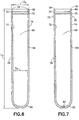
- the outer tube 34 as shown in FIGS. 6-7 , acts primarily as a carrier for the inner tube 32, providing additional protection for the contents of the inner tube 32 as well as providing external dimensions that are compatible with standard automated clinical laboratory processes, such as Clinical Laboratory Automation.
- the specimen cap 86 as shown in FIGS. 2-3 , provides a means for a user to access the inner tube 32 to obtain the specimen deposited therein, and also provides a leak proof seal with the inner tube 32 upon replacement of the specimen cap 86, as will be discussed herein.
- the inner tube 32 includes an open top end 38, a closed bottom end 40, and a sidewall 42 extending therebetween defining an inner tube interior 44 adapted to receive a specimen therein.
- the open top end 38 may include at least one funnel 46 or scoop portion for facilitating and directing a specimen into the interior 44 of the inner tube 32.
- the funnel 46 includes at least one introducing surface 48 having a curvature for guiding a specimen down the funnel 46 and into the interior 44 of the inner tube 32.
- the funnel 46 may be placed adjacent a specimen and used to "scoop" the specimen into the inner tube 32.
- the funnel 46 may be placed adjacent a patient's fingertip, and the funnel 46 may be used to scoop capillary blood into the inner tube 32.
- the open top end 38 of the inner tube 32 may include dual funnels 46A, 46B.
- the dual funnels 46A, 46B may be offset, such that the curvature of the introducing surface 48A of the first funnel 46A faces the corresponding curvature of the introducing surface 48B of the second funnel 46B, thereby forming a finger receiving surface 50.
- a patient's finger tip may be placed in contact with the finger receiving surface 50 for directing capillary blood into the interior 44 of the inner tube 32.
- the inner tube 32 may also include an annular ring 52 disposed about a portion of the sidewall 42.
- the annular ring 52 is disposed adjacent the open top end 38 and extends outwardly from an exterior surface 54 of the sidewall 42.
- the inner tube 32 may further include an annular protrusion 68 extending outwardly from the exterior surface 54 of the sidewall 42.
- the annular protrusion 68 may extend inwardly into an interior of the inner tube 32.
- the annular protrusion 68 may be positioned below the annular ring 52.
- the open top end 38 of the inner tube 32 may be adapted to provide a sufficiently wide opening to allow standard diagnostic and sampling probes, needles, and/or similar extraction or deposition devices to enter the open top end 38 and access the interior 44 for the purpose of depositing a specimen therein or withdrawing a specimen therefrom.
- the interior 44 of the inner tube 32 may include at least one angled directing surface 58 for directing a standard instrument probe or other device toward the closed bottom end 40 of the inner tube 32. In certain configurations it is desirable for both the introducing surface 48 of the funnel 46 and the angled directing surface 58 to be smooth and gradual surfaces to promote the flow of specimen into the interior 44 of the inner tube 32.
- the dimensions of the inner tube 32 are balanced such that the open top end has an opening having a sufficient width W, as shown in FIG. 4 , to allow a standard instrument probe to pass therethrough, and also to have an inner tube diameter D sufficient to provide the greatest column height of a specimen disposed within the interior 44 of the inner tube 32.
- an increased specimen column height within the inner tube 32 provides for a greater volume of specimen that may be retrieved or extracted by an analyzer probe (not shown).
- At least one stabilizer 56 may be provided on the exterior surface 54 of the sidewall 42.
- the stabilizer 56 as shown in FIGS. 4-5 , may have any suitable shape such that an outer surface 59 contacts at least a portion of the outer tube 34, as shown in FIGS. 6-7 .
- the outer tube 34 has an open top end 60, a closed bottom end 62, and a sidewall 64 extending therebetween and forming an outer tube interior 66.
- the sidewall 64 of the outer tube 34 includes an inner surface 72 and an outer surface 74 and may include at least one recess 70 extending into a portion of the sidewall 64, such as into the inner surface 72 of a portion of the sidewall 64 adjacent the open top end 60.
- the recess 70 is adapted to receive at least a portion of the annular protrusion 68 of the inner tube 32 therein during assembly.
- the outer surface 74 may also include an annular ring 76 extending outwardly from the outer surface 74 of the sidewall 64 adjacent the open top end 60.
- the annular ring 76 is positioned below the recess 70 along the sidewall 64.
- the outer tube 34 is dimensioned to receive the inner tube, as shown in FIGS. 4-5 at least partially therein, as shown in FIGS. 8-9 .
- the outer tube 34 has sufficient inner dimensions to accommodate the inner tube 32 therein.
- the inner tube 32 may be at least partially positioned within the outer tube 34 such that an upper end 78 of the outer tube 34 abuts the annular ring 52 of the inner tube 32 allowing for a receiving portion of the inner tube having a length L, shown in FIG. 4 , to be received within the outer tube interior 66, as shown in FIG. 8 .
- FIG. 8 Referring specifically to FIG.
- the receiving portion of the inner tube 32 has a diameter Di that is dimensioned for receipt within the outer tube interior 66 and is smaller than the inner diameter D 3 of the outer tube 34, as shown in FIG. 6 .
- the annular ring 52 of the inner tube 32 is dimensioned to restrain any further portion of the inner tube 32 from passing within the outer tube 34 and has a diameter D 2 , shown in FIG. 4 , that is greater than the inner diameter D 3 of the outer tube 34.
- the recess 70 of the outer tube 34 is adapted to receive at least a portion of the annular protrusion 68 of the inner tube 32 therein, as shown in FIGS. 8-9 .
- the inner tube 32 and the outer tube 34 may have any suitable dimensions
- the inner tube may have an overall length L 2 of about 48 mm, as shown in FIG. 5 , and have an inner tube diameter D of about 7 mm, as shown in FIG. 4 .
- the outer tube 34 may have any suitable dimensions that are compatible with standard industry specifications for automated clinical processes, such as having an overall length L 3 of about 69 mm, as shown in FIG. 6 , and an outer diameter D 4 of about 13 mm.
- the outer tube 34 may also be dimensioned to accommodate standard size labels applied to the outer surface 74 and may be dimensioned to improve manipulation by a clinician. This can be particularly advantageous when collecting small volume samples of specimen.
- the overall length L 5 may be the industry standard length of 75 mm, as shown in FIG. 8 , or an industry standard length of 100 mm.
- the inner tube 32 and the outer tube 34 may be in-molded in which both the inner tube 32 and the outer tube 34 are molded in the same press and assembled, as opposed to being separately molded and subsequently assembled.
- the inner tube 32 and the outer tube 34 may be press-fit within the same forming process.
- the tolerances of the relative engagement between the inner tube 32 and the outer tube 34 may be improved because the relative rate of shrink is the same for both tubes.
- the inner tube 32 and the outer tube 34 may be formed of the same material, such as polypropylene and/or polyethylene. In other configurations, the inner tube 32 and the outer tube 34 may be formed of two different polymeric materials.
- an assembly having an inner tube 32 and an outer tube 34 having thin walls allows for optical clarity of the sample when viewed by an automated vision system, assisting in sample and quality detection.
- increased optical clarity may assist a medical practitioner during collection of a specimen.
- the bottom end 62 of the outer tube 34 may include a vent 80, as shown in FIG. 7 , for allowing air trapped between the inner surface of the outer tube 34 and the exterior surface 54 of the sidewall 42 of the inner tube 32 to escape therethrough.
- the vent 80 may also assist in the molding process of the inner tube 32 by locking the core pin of the mold during the molding process to prevent relative shifting between the outer tube 34 and the formation of the inner tube 32.
- At least one of the inner tube 32 and the outer tube 34 include at least one fill-line 82, shown in FIGS. 4-5 , for allowing a clinician to determine the volume of specimen within the inner tube 32.
- at least one of the inner tube 32 and the outer tube 34 includes a colored or light blocking additive 84, as shown in FIG. 8 .
- the additive may allow sufficient light to pass through the sidewall 42 of the inner tube 32 to allow a clinician to visualize the contents of the interior 44 of the inner tube 32, and to also prevent enough light from passing through the sidewall 42 of the inner tube 32 to compromise or otherwise alter the contents of the inner tube 32.
- the additive may be sprayed, coated, or in-molded with at least one of the inner tube 32 and the outer tube 34.
- the additive is intended to block only certain wavelengths of light from passing through the sidewall 42 of the inner tube 32.
- a specimen collection cap 86 is provided for sealing the open top end 38 of the inner tube 32 and/or the open top end 60 of the outer tube 34.
- the open top end 60 of the outer tube 34 is sealed by the open top end 38 of the inner tube 32, specifically by the annular ring 52 of the inner tube 32.
- the specimen collection cap 86 may only seal the open top end 38 of the inner tube 32 but effectively seals the open top end 60 of the outer tube 34 as well.
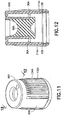
- the specimen collection cap 86 includes a top surface 88 and an annular shoulder 90 depending therefrom.
- the specimen collection cap 86 may also include an annular interior wall 92 depending from the top surface 88, with the annular shoulder 90 circumferentially disposed about the annular interior wall 92 and spaced therefrom by a tube receiving portion 94.
- an elastomeric stopper or pierceable septum 96 may be disposed at least partially within the annular interior wall 92 and extending therebetween forming a sealing body within the specimen collection cap 86.
- the pierceable septum 96 is formed from a thermoplastic elastomer (TPE).
- TPE thermoplastic elastomer
- the pierceable septum 96 may be pierced by a needle cannula or probe, as is conventionally known, and may be self-sealing.
- the pierceable septum 96 may be formed through an offset flow channel 98, as is described in United States Patent Publication No. 2009/0308184 , the entire disclosure of which is hereby incorporated by reference.
- the pierceable septum 96 may include a concave receiving surface 100 adjacent the top surface 88 for directing an instrument, such as a needle cannula or a probe, to the apex 102 of the concave receiving surface 100. This allows a clinician to more easily determine proper placement of the needle cannula or probe for puncturing the pierceable septum 96.
- An opening 104 within the top surface 88 of the specimen collection cap 86 may also be dimensioned to accommodate standard clinical probes and needle cannulae for both hematology and chemistry analysis therethrough.
- the pierceable septum 96 also includes a specimen directing surface 106 for funneling a specimen into an apex 108 of the specimen collection cap 86 when the specimen collection container assembly 30, shown in FIG. 1 , is inverted for specimen withdrawal, as is described in United States Patent Publication No. 2009/0308184 .
- the annular interior wall 92 may have an inner surface 110 contacting the pierceable septum 96.
- a portion of the inner surface 110 of the annular interior wall 92 may include a septum restraining portion 112 for preventing the inadvertent advancement of the pierceable septum 96 through the specimen collection cap 86 when pressure is applied to the pierceable septum 96 by a needle cannula or probe.
- the septum restraining portion 112 extends at least partially into the pierecable septum 96 for creating a physical restraint therebetween.
- the annular shoulder 90 of the specimen collection cap 86 has an inner surface 114 having a first protrusion 116 extending from the inner surface 114 into the tube receiving portion 94, and a second protrusion 118 extending from the inner surface 114 into the tube receiving portion 94.
- the first protrusion 116 is spaced apart from the second protrusion 118, such as laterally offset therefrom along a portion of the inner surface 114 of the annular shoulder 90.
- the first protrusion 116 and the second protrusion 118 may extend annularly into the tube receiving portion 94.
- the annular shoulder 90 is positioned over the exterior surface 54 of the sidewall 42 of the inner tube 32 and the outer surface 74 of the sidewall 64 of the outer tube 34.
- the pierceable septum 96 contacts and forms a barrier seal 122 with a portion of the interior 44 of the inner tube 32, thereby sealing the interior 44 from the external atmosphere.
- the funnel 46, and portions of the open top end 38 of the inner tube 32 and the portions of the open top end 60 of the outer tube 34 are received within the tube receiving portion 94.
- the first protrusion 116 and the second protrusion 118 form a first recess 120 therebetween for accommodating the annular ring 52 of the inner tube 32 therein, thereby forming a first seal 124 between the specimen collection cap 86 and the inner tube 32.
- the specimen collection cap 86 may also include a third protrusion 126 extending from the inner surface 114 of the annular shoulder 90 into the tube receiving portion 94.
- the third protrusion 126 may extend annularly into the tube receiving portion 94 and may be provided adjacent a bottom end 128 of the annular shoulder 90.
- the third protrusion 126 may engage a portion of the outer surface 74 of the sidewall 64 of the outer tube 34 forming a second seal 130.
- the barrier seal 122 formed between the pierceable septum 96 and the interior 44 of the inner tube 32 maintains the interior 44 in a sterile condition prior to receipt of a specimen therein.
- the barrier seal 122 also maintains the condition of the specimen present within the inner tube 32 after recapping or re-sealing of the pierceable septum 96.
- the first seal 124 and the second seal 130 form a tortuous path between the external atmosphere and the barrier seal 122 further enhancing the overall sealing system of the specimen collection container assembly 30, shown in FIG. 1 .
- the first seal 124 and the second seal 130 maintain the funnel 46 in a sterile condition prior to use.
- the annular shoulder 90 of the specimen collection cap 86 may include a plurality of ribs 132 extending along a portion of an exterior surface 134 of the annular shoulder 90. These ribs 132 may be used to help identify the intended contents of the inner tube 32, additives and/or amounts of additives present within the inner tube 32, and/or the intended testing procedure to be performed on the contents of the inner tube 32.
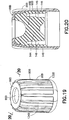
- an alternative specimen collection cap 86A is shown.
- the specimen collection cap 86A is adapted for use with the inner tube 32 and/or the outer tube 34 as described herein, and is substantially similar to the specimen collection cap 86, with several alternatives.
- a sealing band 138 is disposed annularly about an interior surface 114A of an annular shoulder 90A and extends into a tube receiving portion 94A.
- the sealing band 138 forms a hermetic seal 136 with a portion of the outer surface 74 of the outer tube 34.
- the sealing band 138 is deformable against an annular ring 76 extending from the outer surface 74 of the outer tube 34, as shown in FIG. 7 , to form the hermetic seal 136.
- the annular shoulder 90A of the specimen collection cap 86A may include a strengthening member 140 adjacent the sealing band 138 for providing additional rigidity to the specimen collection cap 86A during engagement with the inner tube 32 and/or the outer tube 34.
- a seal 142 is formed by the interaction of the hermetic seal 136 and the interaction of a first protrusion 116A extending from the inner surface 114A of the annular shoulder 90A into the tube receiving portion 94A and the annular ring 52 of the inner tube 32.
- the seal 142 and the hermetic seal 136 form a tortuous path between the external atmosphere and the barrier seal 122A further enhancing the overall sealing system of the specimen collection container assembly 30, shown in FIG. 1 .
- the engagement of the sealing band 138 and the annular ring 76 extending from the outer surface 74 of the outer tube 34 produces an audible and/or tactile indication that the specimen collection cap 86A and the outer tube 34 with the inner tube 32 disposed therein are sealingly engaged.
- the annular ring 76 may include a resistance protrusion and the sealing band 138 may include a corresponding resistance recess for accommodating the resistance protrusion therein.
- the annular shoulder 90A of the specimen collection cap 86A may include a plurality of alternative ribs 132A extending along a portion of an exterior surface 134A of the annular shoulder 90A. These ribs 132A may be used to help identify the intended contents of the inner tube 32, additives and/or amounts of additives present within the inner tube 32, and/or the intended testing procedure to be performed on the contents of the inner tube 32.
- the specimen collection cap 86A is also suitable for use with inner tube 32 having dual funnels 46A, 46B.
- the dual funnels 46A, 46B are each received within the tube receiving portion 94A, as described herein.
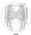
- the specimen collection cap 86B is adapted for use with the inner tube 32 and/or the outer tube 34 as described herein, and is substantially similar to the specimen collection cap 86, with several alternatives.
- the specimen collection cap 86B includes a top surface 88B having an annular shoulder 90B depending therefrom and at least partially surrounding the pierceable septum 96B.
- the pierceable septum 96B includes a base portion 144 and an outer portion 146 circumferentially disposed about the base portion 144 and defining a tube receiving portion 148 therebetween.
- the funnel 46 such as dual funnels 46A, 46B
- the tube receiving portion 148 may be dimensioned such that a spacing gap 152 is present on either side of the funnels 46A, 46B when the inner tube 32 is engaged with the specimen collection cap 86B.
- the spacing gap 152 reduces contact between the funnels 46A, 46B and the pierceable septum 96B during assembly of the specimen collection cap 86B and the inner tube 32. This may be particularly advantageous for preventing or minimizing pull-away of the pierceable septum 96B during disengagement of the specimen collection cap 86B and the inner tube 32.
- a bottom end 150 of the outer portion 146 of the pierceable septum 96B may include a tapered surface 154 for guiding the open top end 38, particularly the funnels 46A, 46B into the tube receiving portion 148 of the pierceable septum 96B.
- the pierceable septum 96B may contact and form a barrier seal 122 with a portion of the interior 44 of the inner tube 32, thereby sealing the interior 44 from the external atmosphere, as described herein.
- the pierceable septum 96B may also form a perimeter seal 156 between a portion of the outer portion 146 and the annular ring 52 of the inner tube 32.
- an upper tip 160 of the funnels 46A, 46B may contact an uppermost region 162 of the tube receiving portion 148 forming a tertiary seal 164 therebetween.
- the tertiary seal 164 and the perimeter seal 156 form a tortuous path between the external atmosphere and the barrier seal 122 further enhancing the overall sealing system of a specimen collection container assembly 30B, shown in FIG. 18 .
- an inner surface 114B of the annular shoulder 90B may include a septum restraining portion 112B for preventing the inadvertent advancement of the pierceable septum 96B through the specimen collection cap 86B when pressure is applied to the pierceable septum 96B by a needle cannula or probe.
- the septum restraining portion 112B extends at least partially into the pierceable septum 96B for creating a physical restraint therebetween.
- the pierceable septum 96B may include a restraining portion 170 for bearing against an inner surface 172 of the top surface 88B for preventing inadvertent disengagement of the specimen collection cap 86B.
- the annular shoulder 90B of the specimen collection cap 86B may include a plurality of alternative ribs 132B extending along a portion of an exterior surface 134B of the annular shoulder 90B. These ribs 132B may be used to help identify the intended contents of the inner tube 32, additives and/or amounts of additives present within the inner tube 32, and/or the intended testing procedure to be performed on the contents of the inner tube 32.
Landscapes
- Health & Medical Sciences (AREA)
- Chemical & Material Sciences (AREA)
- Analytical Chemistry (AREA)
- General Health & Medical Sciences (AREA)
- Hematology (AREA)
- Clinical Laboratory Science (AREA)
- Chemical Kinetics & Catalysis (AREA)
- Sampling And Sample Adjustment (AREA)
- Investigating Or Analysing Biological Materials (AREA)
- Measurement Of The Respiration, Hearing Ability, Form, And Blood Characteristics Of Living Organisms (AREA)
- Medical Preparation Storing Or Oral Administration Devices (AREA)
Applications Claiming Priority (5)
| Application Number | Priority Date | Filing Date | Title |
|---|---|---|---|
| US41958710P | 2010-12-03 | 2010-12-03 | |
| US13/295,235 US8460620B2 (en) | 2010-12-03 | 2011-11-14 | Specimen collection container assembly |
| EP11790822.8A EP2646158B1 (fr) | 2010-12-03 | 2011-11-15 | Assemblée pour tubes prélèvement aux essaies |
| PCT/US2011/060781 WO2012074738A1 (fr) | 2010-12-03 | 2011-11-15 | Ensemble récipient de collecte d'échantillons |
| EP17207073.2A EP3320974B1 (fr) | 2010-12-03 | 2011-11-15 | Ensemble récipient de collecte d'échantillons |
Related Parent Applications (2)
| Application Number | Title | Priority Date | Filing Date |
|---|---|---|---|
| EP17207073.2A Division EP3320974B1 (fr) | 2010-12-03 | 2011-11-15 | Ensemble récipient de collecte d'échantillons |
| EP11790822.8A Division EP2646158B1 (fr) | 2010-12-03 | 2011-11-15 | Assemblée pour tubes prélèvement aux essaies |
Publications (1)
| Publication Number | Publication Date |
|---|---|
| EP3871775A1 true EP3871775A1 (fr) | 2021-09-01 |
Family
ID=46162419
Family Applications (3)
| Application Number | Title | Priority Date | Filing Date |
|---|---|---|---|
| EP17207073.2A Active EP3320974B1 (fr) | 2010-12-03 | 2011-11-15 | Ensemble récipient de collecte d'échantillons |
| EP21166535.1A Pending EP3871775A1 (fr) | 2010-12-03 | 2011-11-15 | Ensemble récipient de collecte d'échantillons |
| EP11790822.8A Active EP2646158B1 (fr) | 2010-12-03 | 2011-11-15 | Assemblée pour tubes prélèvement aux essaies |
Family Applications Before (1)
| Application Number | Title | Priority Date | Filing Date |
|---|---|---|---|
| EP17207073.2A Active EP3320974B1 (fr) | 2010-12-03 | 2011-11-15 | Ensemble récipient de collecte d'échantillons |
Family Applications After (1)
| Application Number | Title | Priority Date | Filing Date |
|---|---|---|---|
| EP11790822.8A Active EP2646158B1 (fr) | 2010-12-03 | 2011-11-15 | Assemblée pour tubes prélèvement aux essaies |
Country Status (10)
| Country | Link |
|---|---|
| US (3) | US8460620B2 (fr) |
| EP (3) | EP3320974B1 (fr) |
| JP (3) | JP5670583B2 (fr) |
| CN (1) | CN103237602B (fr) |
| AU (1) | AU2011337010B2 (fr) |
| BR (1) | BR112013013251B1 (fr) |
| CA (1) | CA2818606C (fr) |
| ES (2) | ES2866982T3 (fr) |
| MX (1) | MX356294B (fr) |
| WO (1) | WO2012074738A1 (fr) |
Families Citing this family (33)
| Publication number | Priority date | Publication date | Assignee | Title |
|---|---|---|---|---|
| US8460620B2 (en) | 2010-12-03 | 2013-06-11 | Becton, Dickinson And Company | Specimen collection container assembly |
| WO2012177656A2 (fr) | 2011-06-19 | 2012-12-27 | Abogen, Inc. | Dispositifs, solutions et procédés de recueillement d'échantillons |
| US10500589B2 (en) * | 2013-03-01 | 2019-12-10 | Siemens Healthcare Diagnostics Inc. | Self aligning wedge container with anti-evaporation tube |
| AU2013202778A1 (en) | 2013-03-14 | 2014-10-02 | Gen-Probe Incorporated | Systems, methods, and apparatuses for performing automated reagent-based assays |
| AU2013202805B2 (en) | 2013-03-14 | 2015-07-16 | Gen-Probe Incorporated | System and method for extending the capabilities of a diagnostic analyzer |
| CN103284731B (zh) * | 2013-06-04 | 2015-01-07 | 威海鸿宇医疗器械有限公司 | 避光采血管 |
| USD754361S1 (en) * | 2013-09-06 | 2016-04-19 | Theranos, Inc. | Sample container |
| AT514833B1 (de) | 2013-10-11 | 2015-07-15 | Greiner Bio One Gmbh | Abnahmebaugruppe, insbesondere für Blutproben |
| US10245380B2 (en) | 2013-12-27 | 2019-04-02 | William Beaumont Hospital | Container closure, container assembly and method for utilizing the same |
| EP3134210A4 (fr) * | 2014-04-25 | 2017-06-28 | Siemens Healthcare Diagnostics Inc. | Unité de prélèvement d'échantillon |
| WO2015187849A2 (fr) | 2014-06-04 | 2015-12-10 | Lucigen Corporation | Prélèvement d'échantillons et dispositifs d'analyse |
| US12038434B2 (en) | 2015-02-09 | 2024-07-16 | DNA Genotek, Inc. | Devices, solutions and methods for sample collection related applications, analysis and diagnosis |
| JP6820865B2 (ja) | 2015-04-29 | 2021-01-27 | ペルキネルマー ヘルス サイエンシーズ, インコーポレイテッド | 試料収集および送達装置 |
| CN106466645A (zh) * | 2015-08-21 | 2017-03-01 | 无锡市凯顺医疗器械制造有限公司 | 一种试管 |
| ITUB20153258A1 (it) * | 2015-08-27 | 2017-02-27 | Copan Italia Spa | Dispositivo per il prelievo, il trasferimento e la conservazione di campioni di materiale biologico e/o chimico |
| JP6958601B2 (ja) * | 2015-12-03 | 2021-11-02 | ニプロ株式会社 | 二重管 |
| USD843008S1 (en) | 2016-01-15 | 2019-03-12 | Biotix, Inc. | Fluid handling tube with cap |
| US20190015830A1 (en) * | 2016-01-15 | 2019-01-17 | Biotix, Inc. | Cap and fluid handling tube components and assemblies |
| EP3414195B1 (fr) * | 2016-02-08 | 2024-11-06 | Nolato Treff AG Degersheim | Flacon et procédé de transport de flacons |
| USD803395S1 (en) * | 2016-05-10 | 2017-11-21 | Peter Equere | Male urinary incontinence protection sheath |
| US9999888B2 (en) * | 2016-05-19 | 2018-06-19 | Integrated Lab Solutions, Inc. | Specimen container for urine and other liquids |
| WO2017210515A1 (fr) | 2016-06-03 | 2017-12-07 | Advanced Instruments, Llc | Bouchon pour coupelle d'échantillon d'osmométrie |
| USD865212S1 (en) * | 2016-08-15 | 2019-10-29 | Kobe Bio Robotix Co., Ltd | Sample storage |
| US11305286B2 (en) | 2017-05-02 | 2022-04-19 | Greiner Bio-One Gmbh | Collection assembly or test tube for a small amount of a body fluid, comprising an extender element |
| WO2018208863A1 (fr) * | 2017-05-08 | 2018-11-15 | Claudia Santamaria | Dispositif de protection d'un récipient interne |
| CN111194400B (zh) * | 2017-11-06 | 2022-02-11 | 卡尔巴科特公司 | 量热计和用于量热计的样品容器 |
| CN210982483U (zh) * | 2018-04-24 | 2020-07-10 | 深圳市帝迈生物技术有限公司 | 一种血样自动混匀装置及血细胞分析设备 |
| CN210401441U (zh) * | 2018-04-24 | 2020-04-24 | 深圳市帝迈生物技术有限公司 | 全自动进样血细胞分析测量装置及末梢血试管 |
| CN109738656B (zh) * | 2019-01-29 | 2022-02-08 | 河北艾欧路生物科技有限责任公司 | 一种脑脊液尿总蛋白测定试剂盒及试剂制备方法 |
| CN111772646B (zh) * | 2020-08-11 | 2022-01-28 | 无锡市第五人民医院 | 低样本容量取样器 |
| KR102458602B1 (ko) * | 2021-06-05 | 2022-10-25 | (주)바이온라이프사이언스 | 검체 보관용 용기 덮개 |
| CA3223370A1 (fr) * | 2021-06-29 | 2023-01-05 | Anthony V. Torris | Recipient d'echantillon pour prelevement sanguin capillaire |
| USD1082034S1 (en) * | 2021-10-28 | 2025-07-01 | Bionlifescience, Inc. | Container for specimen storage |
Citations (5)
| Publication number | Priority date | Publication date | Assignee | Title |
|---|---|---|---|---|
| GB2183159A (en) * | 1985-11-19 | 1987-06-03 | Sarstedt Kunststoff | Blood collecting vessel |
| EP0627197A2 (fr) * | 1993-05-12 | 1994-12-07 | Becton, Dickinson and Company | Dispositif collecteur |
| EP0901821A2 (fr) * | 1997-09-12 | 1999-03-17 | Becton, Dickinson and Company | Dispositif avec récipient de prélèvement |
| US20030213312A1 (en) * | 2002-05-17 | 2003-11-20 | Bayer Corporation | Serum transfer cup |
| WO2009111622A2 (fr) * | 2008-03-05 | 2009-09-11 | Becton, Dickinson And Company | Bouchon perforable comoulé et son procédé de fabrication |
Family Cites Families (158)
| Publication number | Priority date | Publication date | Assignee | Title |
|---|---|---|---|---|
| US2393578A (en) | 1942-01-09 | 1946-01-22 | Sterling Drug Inc | Closure |
| US2594621A (en) | 1950-08-03 | 1952-04-29 | George W Derrick | Blood obtaining instrument |
| US2698272A (en) | 1950-09-29 | 1954-12-28 | Gillon Company Inc | Method of forming needle-penetrable stoppers for containers |
| US2998726A (en) | 1959-03-13 | 1961-09-05 | Dwain R Madden | Tank sampler |
| DE1187954B (de) | 1962-02-18 | 1965-02-25 | Paul Buschle | Patronen-Fuellfederhalter |
| US3136440A (en) * | 1963-06-25 | 1964-06-09 | Becton Dickinson Co | Self sealing pierceable stopper for sealed containers |
| US3297184A (en) | 1963-11-05 | 1967-01-10 | B D Lab Inc | Cap for culture tubes |
| FR1520693A (fr) | 1967-03-01 | 1968-04-12 | Oreal | Nouveau dispositif de bouchage pour flacons ou récipients analogues |
| DE1566542A1 (de) | 1967-11-29 | 1971-02-18 | Wimmer Pharma Gummi Gmbh | Durchstechbarer Verschluss fuer Medizinflaschen |
| US3630191A (en) | 1969-02-27 | 1971-12-28 | Gilford Instr Labor Inc | Apparatus and method for filling capillary tubing with fluids |
| BE759374A (fr) | 1970-06-08 | 1971-04-30 | Ims Ltd | Emballage pour medicament |
| JPS549119B1 (fr) | 1970-09-16 | 1979-04-21 | ||
| US3807955A (en) * | 1971-04-15 | 1974-04-30 | Becton Dickinson Co | Serum/plasma isolator cup |
| JPS51122982A (en) * | 1974-12-23 | 1976-10-27 | Becton Dickinson Co | Small blood sampling unit |
| US4024857A (en) | 1974-12-23 | 1977-05-24 | Becton, Dickinson And Company | Micro blood collection device |
| GB1562900A (en) * | 1975-09-24 | 1980-03-19 | Aes Scient Ltd | Preparation of blood plasma and serum samples |
| US4111326A (en) | 1976-03-04 | 1978-09-05 | Becton, Dickinson And Company | Closure for air evacuated container |
| US4156570A (en) | 1977-04-18 | 1979-05-29 | Robert A. Levine | Apparatus and method for measuring white blood cell and platelet concentrations in blood |
| US4163500A (en) | 1978-01-23 | 1979-08-07 | Siemens Aktiengesellschaft | Bottle seal |
| US4201209A (en) | 1978-05-24 | 1980-05-06 | Leveen Harry H | Molded hypodermic plunger with integral shaft and elastomeric head |
| US4215700A (en) * | 1978-08-25 | 1980-08-05 | Sherwood Medical Industries Inc. | Blood collection device |
| US4227620A (en) | 1979-02-28 | 1980-10-14 | Becton, Dickinson And Company | Specimen collecting tube |
| US4308232A (en) | 1979-07-09 | 1981-12-29 | Sherwood Medical Industries Inc. | Anticoagulant stopper coating |
| US4381275A (en) | 1981-01-30 | 1983-04-26 | Trade Finance International | Stabilized core injection molding of plastic |
| US4411163A (en) | 1981-07-27 | 1983-10-25 | American Hospital Supply Corporation | Ventable sample collection device |
| US4397318A (en) * | 1981-08-10 | 1983-08-09 | Becton Dickinson And Company | Blood collector for microcollection container |
| JPS5886173A (ja) | 1981-11-16 | 1983-05-23 | 東洋製罐株式会社 | 輸液用容器の栓及びその製造方法 |
| US4803031A (en) | 1982-06-03 | 1989-02-07 | Anchor Hocking Corporation | Method and apparatus for molding a closure cap |
| US4508676A (en) | 1982-07-29 | 1985-04-02 | Sorensen Jens Ole | Core stabilization by sequential injections |
| US4635807A (en) | 1983-03-17 | 1987-01-13 | Schering Corporation | Stopper for sterile fluid containers |
| US4724028A (en) | 1983-04-15 | 1988-02-09 | Baxter Travenol Laboratories | Method of manufacturing disc-shaped rubber articles, such as injection sites |
| SE437348B (sv) | 1983-07-29 | 1985-02-25 | Pharmacia Ab | Forslutningsanordning for fluidumtet tillslutning av en oppning hos en fluidumbehallare eller fluidumledning |
| US4558947A (en) | 1983-11-07 | 1985-12-17 | Wardlaw Stephen C | Method and apparatus for measuring blood constituent counts |
| USD285115S (en) | 1983-12-05 | 1986-08-12 | Terumo Medical Corporation | Collector for capillary blood |
| US4576185A (en) | 1983-12-05 | 1986-03-18 | Terumo Medical Corporation | Collection device for capillary blood |
| JPS60124902U (ja) * | 1984-01-31 | 1985-08-23 | テルモ株式会社 | 微量採血器具 |
| US4620549A (en) * | 1985-01-25 | 1986-11-04 | Becton, Dickinson And Company | Blood collection assembly |
| JPS61247459A (ja) | 1985-04-25 | 1986-11-04 | テルモ株式会社 | 医療容器用栓体 |
| EP0204486B1 (fr) | 1985-05-28 | 1990-10-17 | Daikyo Gomu Seiko Ltd. | Bouchon en laminé résine/caoutchouc et sa fabrication |
| US4690153A (en) | 1985-11-29 | 1987-09-01 | Becton, Dickinson And Company | Flow inducing means for small volume containers |
| JPH0452685Y2 (fr) * | 1986-06-24 | 1992-12-10 | ||
| US5019243A (en) | 1987-04-03 | 1991-05-28 | Mcewen James A | Apparatus for collecting blood |
| US4791938A (en) | 1987-11-16 | 1988-12-20 | Nanci Van Valkenburg | Capillary blood collector and method |
| US4869384A (en) | 1988-01-12 | 1989-09-26 | International Medication Systems Limited | Package for toxic and dangerous drugs |
| US4893636A (en) | 1988-03-09 | 1990-01-16 | Sherwood Medical Company | Medical container stopper |
| US5275299A (en) | 1988-04-15 | 1994-01-04 | C. A. Greiner & Sohne Gesellschaft Mbh | Closure device for an in particular evacuable cylindrical housing |
| DE3818238A1 (de) | 1988-05-28 | 1989-11-30 | Eppendorf Geraetebau Netheler | Verfahren zur fluessigkeitsentnahme aus grossvolumigen, tiefen gefaessen und vorrichtung zur durchfuehrung des verfahrens durch ansauggefaesse mit kurzen saugstuecken als ansaughilfe |
| USD321456S (en) | 1988-11-21 | 1991-11-12 | Dart Industries, Inc. | Cover for a food storage container or the like |
| US4967919A (en) | 1988-11-23 | 1990-11-06 | Sherwood Medical Company | Blood collection tube safety cap |
| US5103836A (en) * | 1990-02-28 | 1992-04-14 | Epitope, Inc. | Oral collection device and kit for immunoassay |
| JPH0620764B2 (ja) | 1989-10-23 | 1994-03-23 | 株式会社ニッショー | バイアル用ゴム栓の製造方法 |
| US5277874A (en) * | 1990-02-12 | 1994-01-11 | Vasta Gloria J | Mold apparatus for thermally processing a rimmed, sealed, food-filled, plastic container |
| USD325170S (en) | 1990-04-11 | 1992-04-07 | Frantz Dale A | Container lid with spout |
| US5060812A (en) | 1990-09-06 | 1991-10-29 | International Medication Systems, Limited | Medication container stopper which can be punctured by nozzle of a hypodermic syringe |
| USD330660S (en) | 1990-12-06 | 1992-11-03 | Dart Industries, Inc. | Casserole dish cover |
| US5268148A (en) * | 1990-12-18 | 1993-12-07 | Saliva Diagnostic Systems, Inc. | Saliva sampling device and sample adequacy system |
| JPH0774772B2 (ja) | 1990-12-31 | 1995-08-09 | エイ. レビン ロバート | 血液サンプリング組立体、ターゲット細胞の採取方法およびターゲット成分の採取方法 |
| USD334710S (en) | 1991-03-28 | 1993-04-13 | Dart Industries Inc. | Container cover |
| JPH04347141A (ja) | 1991-05-23 | 1992-12-02 | Nissho Corp | 微量血液採取装置 |
| CA2067695C (fr) * | 1991-06-06 | 1997-07-08 | James A. Burns | Assemblage de tube de microcollecte de sang |
| US5279606A (en) | 1991-08-28 | 1994-01-18 | Habley Medical Technology Corporation | Non-reactive composite sealing barrier |
| US5215102A (en) | 1991-10-25 | 1993-06-01 | La Mina Ltd. | Capillary blood antigen testing apparatus |
| US5286453A (en) | 1992-04-02 | 1994-02-15 | Pope Carolyn M | Device for dispensing a biological fluid from a sealed vacuum tube |
| US5232109A (en) | 1992-06-02 | 1993-08-03 | Sterling Winthrop Inc. | Double-seal stopper for parenteral bottle |
| US5379907A (en) | 1993-03-03 | 1995-01-10 | Sterling Winthrop Inc. | Stopper for medication container |
| AU5756094A (en) | 1993-03-31 | 1994-10-06 | Becton Dickinson & Company | Stopper for small diameter blood collection tube |
| CA2094317C (fr) | 1993-04-19 | 2003-01-07 | Victor Daykin | Systeme de collecte de specimens biologiques |
| US5632396A (en) | 1993-05-06 | 1997-05-27 | Becton, Dickinson And Company | Combination stopper-shield closure |
| US5494170A (en) | 1993-05-06 | 1996-02-27 | Becton Dickinson And Company | Combination stopper-shield closure |
| US6939514B1 (en) | 1993-05-14 | 2005-09-06 | Helena Laboratories Corporation | Method and apparatus for dispensing and distributing biological sample |
| USD356643S (en) | 1993-05-27 | 1995-03-21 | Becton Dickinson And Company | Microcollection tube |
| USD357985S (en) | 1993-05-27 | 1995-05-02 | Becton Dickinson And Company | Microcollection tube |
| US5484566A (en) | 1994-03-07 | 1996-01-16 | Wheaton Inc. | Method of manufacture of a partially laminated rubber closure |
| US5527513A (en) | 1994-04-08 | 1996-06-18 | Becton Dickinson And Company | Collection assembly |
| DK0688652T3 (da) | 1994-06-06 | 2000-10-23 | Husky Injection Molding | Sprøjtestøbefremgangsmåde med modstående indløb |
| JPH0843959A (ja) | 1994-07-29 | 1996-02-16 | Fuji Photo Film Co Ltd | 写真焼付装置用照射光源装置 |
| US5458113A (en) | 1994-08-12 | 1995-10-17 | Becton Dickinson And Company | Collection assembly |
| US5647939A (en) | 1994-12-05 | 1997-07-15 | Integrated Liner Technologies, Inc. | Method of bonding a cured elastomer to plastic and metal surfaces |
| JP3634438B2 (ja) * | 1995-04-21 | 2005-03-30 | 積水化学工業株式会社 | 真空採液管 |
| US5634474A (en) | 1995-04-28 | 1997-06-03 | Becton, Dickinson And Company | Blood collection assembly including clot-accelerating glass insert |
| US5711875A (en) | 1995-11-30 | 1998-01-27 | Becton Dickinson And Company | Cell strainer cap |
| US5716683A (en) | 1996-01-30 | 1998-02-10 | Becton, Dickinson And Company | Blood collection tube assembly |
| US5714125A (en) | 1996-03-07 | 1998-02-03 | Medical Safety Products, Inc. | Device for collecting a blood sample from a plastic segment tube |
| US6727101B1 (en) | 1996-03-07 | 2004-04-27 | Baxter International Inc. | Device for removing a blood sample from a plastic segment tube |
| US5785925A (en) | 1996-08-29 | 1998-07-28 | Saigene Corporation | Centrifuge tube phase separation plug |
| DE19647673C2 (de) | 1996-11-19 | 2000-08-24 | Sarstedt Ag & Co | Probengefäß zur Blutabnahme |
| US5902276A (en) | 1996-11-26 | 1999-05-11 | Liebel-Flarsheim Company | Two-shot molded plunger |
| US6071454A (en) | 1997-01-22 | 2000-06-06 | Chisso Corporation | Method for producing a composite molded article of thermoplastic resins |
| US6720044B2 (en) | 1997-02-20 | 2004-04-13 | Pharmacia Ab | Polyolefinic closures comprising penetrable plugs and annular channels |
| US5954104A (en) | 1997-02-28 | 1999-09-21 | Abbott Laboratories | Container cap assembly having an enclosed penetrator |
| US5889584A (en) | 1997-03-10 | 1999-03-30 | Robert A. Levine | Assembly for rapid measurement of cell layers |
| US5888184A (en) | 1997-03-10 | 1999-03-30 | Robert A. Levine | Method for rapid measurement of cell layers |
| USD397295S (en) | 1997-03-17 | 1998-08-25 | Paige Shelton-Ferrell | Dosage indicator |
| US5942191A (en) * | 1997-07-14 | 1999-08-24 | Becton, Dickinson And Company | Body fluid collection vessel having reduced capacity |
| US20020156439A1 (en) | 1997-09-12 | 2002-10-24 | Michael J. Iskra | Collection container assembly |
| JP3872893B2 (ja) * | 1997-12-19 | 2007-01-24 | 積水化学工業株式会社 | 真空検体採取管 |
| US6019751A (en) | 1998-01-20 | 2000-02-01 | Bracco Research Usa | Universal connector and a medical container |
| US6165402A (en) | 1998-01-30 | 2000-12-26 | Abbott Laboratories | Method for making a stopper |
| US6080366A (en) | 1998-03-02 | 2000-06-27 | Becton, Dickinson And Company | Disposable blood tube holder |
| US6752965B2 (en) | 1998-03-06 | 2004-06-22 | Abner Levy | Self resealing elastomeric closure |
| US6030582A (en) | 1998-03-06 | 2000-02-29 | Levy; Abner | Self-resealing, puncturable container cap |
| US6221655B1 (en) | 1998-08-01 | 2001-04-24 | Cytosignal | Spin filter assembly for isolation and analysis |
| US6562300B2 (en) | 1998-08-28 | 2003-05-13 | Becton, Dickinson And Company | Collection assembly |
| JP3142521B2 (ja) | 1998-11-04 | 2001-03-07 | 大成プラス株式会社 | 針刺し止栓とその製造方法 |
| US6077235A (en) | 1999-02-23 | 2000-06-20 | Becton, Dickinson And Company | Blood collection assembly and method therefor |
| US6716396B1 (en) | 1999-05-14 | 2004-04-06 | Gen-Probe Incorporated | Penetrable cap |
| US20010020607A1 (en) | 1999-06-25 | 2001-09-13 | Renzo Chiarin | Assembly of a protected stopper and a test tube, said stopper being used for blood sample collecting or biological liquids handling test tubes |
| US6426049B1 (en) | 1999-07-09 | 2002-07-30 | Becton, Dickinson And Company | Collection assembly |
| USD445908S1 (en) | 1999-08-06 | 2001-07-31 | Becton, Dickinson And Company | Stackable tube assembly |
| USD425625S (en) | 1999-08-06 | 2000-05-23 | Becton, Dickinson And Company | Specimen sampling tube |
| DE60015254T2 (de) | 1999-08-18 | 2006-02-02 | Becton, Dickinson And Co. | Verschluss bestehend aus einem Stopfen und einer Schutzkappe |
| US6358476B1 (en) | 1999-09-23 | 2002-03-19 | Sharon A. Innamorato | Microcollection tube assembly |
| US6221307B1 (en) * | 1999-11-10 | 2001-04-24 | Becton Dickinson And Company | Collection container assembly |
| DE19962664C2 (de) | 1999-12-23 | 2003-01-30 | Helvoet Pharma | Verschlußvorrichtung für einen Unterdruck-Probensammelbehälter |
| US20030133844A1 (en) | 2000-02-25 | 2003-07-17 | Conway Hugh T. | Microcollection tube assembly |
| US20030039717A1 (en) | 2000-05-01 | 2003-02-27 | Hwang C. Robin | Injection molding of thermoplastic parts |
| US6695817B1 (en) | 2000-07-11 | 2004-02-24 | Icu Medical, Inc. | Medical valve with positive flow characteristics |
| US6354452B1 (en) | 2000-07-25 | 2002-03-12 | Becton, Dickinson And Company | Collection container assembly |
| US20020020416A1 (en) | 2000-08-11 | 2002-02-21 | David Namey | Two-shot injection molded nasal/oral mask |
| US6551267B1 (en) | 2000-10-18 | 2003-04-22 | Becton, Dickinson And Company | Medical article having blood-contacting surface |
| CN100386441C (zh) | 2000-11-08 | 2008-05-07 | 贝克顿迪肯森公司 | 收集和稳定生物样品的装置、抑制体外基因诱导的方法和制备全血样品的方法 |
| USD489005S1 (en) | 2001-02-28 | 2004-04-27 | Tri State Distribution, Inc. | Bottle cap |
| ATE422965T2 (de) | 2001-03-09 | 2009-03-15 | Gen Probe Inc | Verfahren zum entnehmen von flüssigkeit aus einem behälter mit durchdringbarem verschluss |
| DE10127823C1 (de) | 2001-06-07 | 2002-08-22 | West Pharm Serv Drug Res Ltd | Verschluss für eine Medikamentenflasche sowie Verfahren zu dessen Herstellung |
| US20030028154A1 (en) | 2001-07-31 | 2003-02-06 | Milton Ross | Polymer hypodermic needle and process for producing same design and process for making all-plastic molded-in-one piece hypodermic needle |
| US6686204B2 (en) | 2001-08-27 | 2004-02-03 | Becton, Dickinson & Company | Collection device |
| DE10144892B4 (de) | 2001-09-12 | 2005-09-08 | Disetronic Licensing Ag | Mehrschichtiger Kunststoffkörper |
| US7022289B1 (en) | 2001-10-10 | 2006-04-04 | The United States Of America As Represented By The Secretary Of The Army | Chemical and biological sampling device and kit and method of use thereof |
| EP1346716A4 (fr) | 2001-11-09 | 2010-10-20 | Taisei Plas Co Ltd | Obturateur permettant d'arreter une fuite resultant du percage par une aiguille et procede de fabrication dudit obturateur |
| USD470051S1 (en) | 2002-01-03 | 2003-02-11 | Owens-Illinois Closure Inc. | Container closure |
| US7028858B2 (en) | 2002-02-19 | 2006-04-18 | Stull Technologies, | Quick-twist pop-off closure |
| WO2003095974A2 (fr) | 2002-05-07 | 2003-11-20 | Becton, Dickinson And Company | Ensemble de collecte |
| JP4496407B2 (ja) | 2002-05-13 | 2010-07-07 | ベクトン・ディキンソン・アンド・カンパニー | プロテアーゼ阻害剤試料採取システム |
| ITVI20020131A1 (it) | 2002-06-17 | 2003-12-17 | Vacutest Kima Srl | Tappo con protezione per provette |
| WO2004000661A2 (fr) | 2002-06-25 | 2003-12-31 | Stull Technologies | Capsule a vis inviolable |
| USD481801S1 (en) | 2002-09-20 | 2003-11-04 | Becton, Dickinson And Company | Cap assembly for a roller bottle |
| USD479997S1 (en) | 2002-09-25 | 2003-09-30 | Societe Des Produits Nestle S.A. | Jar cover |
| BE1015362A6 (nl) | 2002-10-14 | 2005-02-01 | Boutech Nv | Werkwijze en inrichting voor het vervaardigen van plunjers voor medische spuiten, plunjers hierdoor verkregen, alsmede spuit voor medische doeleinden. |
| USD490707S1 (en) | 2002-10-15 | 2004-06-01 | Marc J. Mataya | Prescription bottle cap |
| PT1421906E (pt) * | 2002-11-20 | 2006-05-31 | Sarstedt Ag & Co | Recipiente de colecta de urina e acessorios |
| US7574789B2 (en) * | 2003-02-03 | 2009-08-18 | Becton, Dickinson And Company | Container assembly and method for making assembly |
| USD481948S1 (en) | 2003-03-10 | 2003-11-11 | Owens-Illinois Closure Inc. | Squeeze-and-turn child resistant closure |
| USD481946S1 (en) | 2003-03-31 | 2003-11-11 | Brian Gittler | Medicament dosage indicator |
| GB0315953D0 (en) | 2003-07-08 | 2003-08-13 | Glaxosmithkline Biolog Sa | Process |
| WO2005011495A1 (fr) | 2003-07-18 | 2005-02-10 | Sekisui Chemical Co., Ltd. | Recipient ferme hermetiquement et recipient collecteur de substance d'essai sous vide |
| US20050065454A1 (en) * | 2003-09-22 | 2005-03-24 | Becton, Dickinson And Company | Non-evacuated blood collection tube |
| US20050090766A1 (en) | 2003-10-24 | 2005-04-28 | Renzo Montanari | Tube for blood collecting with a vacuum method |
| JP2005221485A (ja) * | 2004-02-09 | 2005-08-18 | Sekisui Chem Co Ltd | 試料収納具 |
| US20060036231A1 (en) | 2004-05-27 | 2006-02-16 | Conard William A | Injection port and method of making the same |
| CN1989409A (zh) | 2004-05-27 | 2007-06-27 | 荣研化学株式会社 | 用于采出生物试样的工具和用于采出生物试样的方法 |
| DE102004044288A1 (de) | 2004-09-10 | 2006-04-06 | Haindl, Hans, Dr.med. | Vorrichtung zur Verbindung eines rohrförmigen Teils, insbesondere einer Kanüle, mit dem Inneren einer Flasche oder dergleichen |
| CA2517940A1 (fr) | 2004-09-24 | 2006-03-24 | Ems-Chemie Ag | Methode de moulage par injection de pieces en plastique |
| USD563785S1 (en) | 2006-04-13 | 2008-03-11 | The Quaker Oats Company | Container cover |
| WO2008031036A1 (fr) * | 2006-09-08 | 2008-03-13 | Becton, Dickinson And Company | Contenant d'échantillon pourvu d'un indicateur de remplissage physique |
| US7909197B2 (en) | 2007-05-07 | 2011-03-22 | Whirlpool Corporation | High volume docking seal for bulk liquid dispensing cartridge |
| CA2717894C (fr) * | 2008-03-05 | 2014-05-27 | Becton, Dickinson And Company | Ensemble recipient et dispositif de collecte a action capillaire |
| USD607340S1 (en) | 2008-04-18 | 2010-01-05 | Henkel Ag & Co. Kgaa | Jar |
| US8460620B2 (en) * | 2010-12-03 | 2013-06-11 | Becton, Dickinson And Company | Specimen collection container assembly |
-
2011
- 2011-11-14 US US13/295,235 patent/US8460620B2/en active Active
- 2011-11-15 EP EP17207073.2A patent/EP3320974B1/fr active Active
- 2011-11-15 ES ES17207073T patent/ES2866982T3/es active Active
- 2011-11-15 CN CN201180058102.3A patent/CN103237602B/zh active Active
- 2011-11-15 EP EP21166535.1A patent/EP3871775A1/fr active Pending
- 2011-11-15 WO PCT/US2011/060781 patent/WO2012074738A1/fr not_active Ceased
- 2011-11-15 CA CA2818606A patent/CA2818606C/fr active Active
- 2011-11-15 JP JP2013542025A patent/JP5670583B2/ja active Active
- 2011-11-15 ES ES11790822.8T patent/ES2663624T3/es active Active
- 2011-11-15 AU AU2011337010A patent/AU2011337010B2/en active Active
- 2011-11-15 BR BR112013013251-5A patent/BR112013013251B1/pt active IP Right Grant
- 2011-11-15 EP EP11790822.8A patent/EP2646158B1/fr active Active
- 2011-11-15 MX MX2013005491A patent/MX356294B/es active IP Right Grant
-
2013
- 2013-05-06 US US13/887,680 patent/US9399218B2/en active Active
-
2014
- 2014-12-17 JP JP2014255510A patent/JP2015083985A/ja active Pending
-
2016
- 2016-06-15 US US15/183,196 patent/US9962704B2/en active Active
- 2016-11-25 JP JP2016229099A patent/JP6271685B2/ja active Active
Patent Citations (6)
| Publication number | Priority date | Publication date | Assignee | Title |
|---|---|---|---|---|
| GB2183159A (en) * | 1985-11-19 | 1987-06-03 | Sarstedt Kunststoff | Blood collecting vessel |
| EP0627197A2 (fr) * | 1993-05-12 | 1994-12-07 | Becton, Dickinson and Company | Dispositif collecteur |
| EP0901821A2 (fr) * | 1997-09-12 | 1999-03-17 | Becton, Dickinson and Company | Dispositif avec récipient de prélèvement |
| US20030213312A1 (en) * | 2002-05-17 | 2003-11-20 | Bayer Corporation | Serum transfer cup |
| WO2009111622A2 (fr) * | 2008-03-05 | 2009-09-11 | Becton, Dickinson And Company | Bouchon perforable comoulé et son procédé de fabrication |
| US20090308184A1 (en) | 2008-03-05 | 2009-12-17 | Becton, Dickinson And Company | Co-Molded Pierceable Stopper and Method for Making the Same |
Also Published As
| Publication number | Publication date |
|---|---|
| AU2011337010A1 (en) | 2013-06-06 |
| MX2013005491A (es) | 2014-11-21 |
| US20160296931A1 (en) | 2016-10-13 |
| CN103237602A (zh) | 2013-08-07 |
| JP6271685B2 (ja) | 2018-01-31 |
| JP5670583B2 (ja) | 2015-02-18 |
| JP2014502357A (ja) | 2014-01-30 |
| EP3320974A1 (fr) | 2018-05-16 |
| US20130251605A1 (en) | 2013-09-26 |
| BR112013013251A2 (pt) | 2016-09-13 |
| WO2012074738A1 (fr) | 2012-06-07 |
| EP2646158A1 (fr) | 2013-10-09 |
| US8460620B2 (en) | 2013-06-11 |
| US9962704B2 (en) | 2018-05-08 |
| US9399218B2 (en) | 2016-07-26 |
| AU2011337010B2 (en) | 2014-09-11 |
| CN103237602B (zh) | 2015-09-16 |
| US20120141341A1 (en) | 2012-06-07 |
| EP2646158B1 (fr) | 2018-01-03 |
| ES2866982T3 (es) | 2021-10-20 |
| ES2663624T3 (es) | 2018-04-16 |
| CA2818606C (fr) | 2015-06-09 |
| BR112013013251B1 (pt) | 2020-11-24 |
| EP3320974B1 (fr) | 2021-04-07 |
| JP2015083985A (ja) | 2015-04-30 |
| MX356294B (es) | 2018-05-22 |
| CA2818606A1 (fr) | 2012-06-07 |
| JP2017067787A (ja) | 2017-04-06 |
Similar Documents
| Publication | Publication Date | Title |
|---|---|---|
| EP2646158B1 (fr) | Assemblée pour tubes prélèvement aux essaies | |
| AU2012203335B2 (en) | Capillary action collection device and container assembly | |
| US6426049B1 (en) | Collection assembly | |
| CN101678931B (zh) | 用于体液容器的密封帽和血液采集装置 | |
| EP4301239B1 (fr) | Récipient de collecte de petit volume | |
| AU2014265050B2 (en) | Specimen collection container assembly |
Legal Events
| Date | Code | Title | Description |
|---|---|---|---|
| PUAI | Public reference made under article 153(3) epc to a published international application that has entered the european phase |
Free format text: ORIGINAL CODE: 0009012 |
|
| STAA | Information on the status of an ep patent application or granted ep patent |
Free format text: STATUS: THE APPLICATION HAS BEEN PUBLISHED |
|
| AC | Divisional application: reference to earlier application |
Ref document number: 3320974 Country of ref document: EP Kind code of ref document: P Ref document number: 2646158 Country of ref document: EP Kind code of ref document: P |
|
| AK | Designated contracting states |
Kind code of ref document: A1 Designated state(s): AL AT BE BG CH CY CZ DE DK EE ES FI FR GB GR HR HU IE IS IT LI LT LU LV MC MK MT NL NO PL PT RO RS SE SI SK SM TR |
|
| STAA | Information on the status of an ep patent application or granted ep patent |
Free format text: STATUS: REQUEST FOR EXAMINATION WAS MADE |
|
| 17P | Request for examination filed |
Effective date: 20220224 |
|
| RBV | Designated contracting states (corrected) |
Designated state(s): AL AT BE BG CH CY CZ DE DK EE ES FI FR GB GR HR HU IE IS IT LI LT LU LV MC MK MT NL NO PL PT RO RS SE SI SK SM TR |
|
| STAA | Information on the status of an ep patent application or granted ep patent |
Free format text: STATUS: EXAMINATION IS IN PROGRESS |
|
| 17Q | First examination report despatched |
Effective date: 20230605 |