EP3871886A1 - Appareil d'enregistrement et programme pour appareil d'enregistrement - Google Patents
Appareil d'enregistrement et programme pour appareil d'enregistrement Download PDFInfo
- Publication number
- EP3871886A1 EP3871886A1 EP19890799.0A EP19890799A EP3871886A1 EP 3871886 A1 EP3871886 A1 EP 3871886A1 EP 19890799 A EP19890799 A EP 19890799A EP 3871886 A1 EP3871886 A1 EP 3871886A1
- Authority
- EP
- European Patent Office
- Prior art keywords
- correction
- areas
- area
- main area
- main
- Prior art date
- Legal status (The legal status is an assumption and is not a legal conclusion. Google has not performed a legal analysis and makes no representation as to the accuracy of the status listed.)
- Granted
Links
Images






Classifications
-
- B—PERFORMING OPERATIONS; TRANSPORTING
- B41—PRINTING; LINING MACHINES; TYPEWRITERS; STAMPS
- B41J—TYPEWRITERS; SELECTIVE PRINTING MECHANISMS, i.e. MECHANISMS PRINTING OTHERWISE THAN FROM A FORME; CORRECTION OF TYPOGRAPHICAL ERRORS
- B41J2/00—Typewriters or selective printing mechanisms characterised by the printing or marking process for which they are designed
- B41J2/005—Typewriters or selective printing mechanisms characterised by the printing or marking process for which they are designed characterised by bringing liquid or particles selectively into contact with a printing material
- B41J2/01—Ink jet
- B41J2/21—Ink jet for multi-colour printing
- B41J2/2132—Print quality control characterised by dot disposition, e.g. for reducing white stripes or banding
-
- B—PERFORMING OPERATIONS; TRANSPORTING
- B41—PRINTING; LINING MACHINES; TYPEWRITERS; STAMPS
- B41J—TYPEWRITERS; SELECTIVE PRINTING MECHANISMS, i.e. MECHANISMS PRINTING OTHERWISE THAN FROM A FORME; CORRECTION OF TYPOGRAPHICAL ERRORS
- B41J2/00—Typewriters or selective printing mechanisms characterised by the printing or marking process for which they are designed
- B41J2/005—Typewriters or selective printing mechanisms characterised by the printing or marking process for which they are designed characterised by bringing liquid or particles selectively into contact with a printing material
- B41J2/01—Ink jet
- B41J2/015—Ink jet characterised by the jet generation process
- B41J2/04—Ink jet characterised by the jet generation process generating single droplets or particles on demand
- B41J2/045—Ink jet characterised by the jet generation process generating single droplets or particles on demand by pressure, e.g. electromechanical transducers
- B41J2/04501—Control methods or devices therefor, e.g. driver circuits, control circuits
- B41J2/04505—Control methods or devices therefor, e.g. driver circuits, control circuits aiming at correcting alignment
-
- B—PERFORMING OPERATIONS; TRANSPORTING
- B41—PRINTING; LINING MACHINES; TYPEWRITERS; STAMPS
- B41J—TYPEWRITERS; SELECTIVE PRINTING MECHANISMS, i.e. MECHANISMS PRINTING OTHERWISE THAN FROM A FORME; CORRECTION OF TYPOGRAPHICAL ERRORS
- B41J2/00—Typewriters or selective printing mechanisms characterised by the printing or marking process for which they are designed
- B41J2/005—Typewriters or selective printing mechanisms characterised by the printing or marking process for which they are designed characterised by bringing liquid or particles selectively into contact with a printing material
- B41J2/01—Ink jet
- B41J2/015—Ink jet characterised by the jet generation process
- B41J2/04—Ink jet characterised by the jet generation process generating single droplets or particles on demand
- B41J2/045—Ink jet characterised by the jet generation process generating single droplets or particles on demand by pressure, e.g. electromechanical transducers
- B41J2/04501—Control methods or devices therefor, e.g. driver circuits, control circuits
- B41J2/04508—Control methods or devices therefor, e.g. driver circuits, control circuits aiming at correcting other parameters
-
- B—PERFORMING OPERATIONS; TRANSPORTING
- B41—PRINTING; LINING MACHINES; TYPEWRITERS; STAMPS
- B41J—TYPEWRITERS; SELECTIVE PRINTING MECHANISMS, i.e. MECHANISMS PRINTING OTHERWISE THAN FROM A FORME; CORRECTION OF TYPOGRAPHICAL ERRORS
- B41J2/00—Typewriters or selective printing mechanisms characterised by the printing or marking process for which they are designed
- B41J2/005—Typewriters or selective printing mechanisms characterised by the printing or marking process for which they are designed characterised by bringing liquid or particles selectively into contact with a printing material
- B41J2/01—Ink jet
- B41J2/015—Ink jet characterised by the jet generation process
- B41J2/04—Ink jet characterised by the jet generation process generating single droplets or particles on demand
- B41J2/045—Ink jet characterised by the jet generation process generating single droplets or particles on demand by pressure, e.g. electromechanical transducers
- B41J2/04501—Control methods or devices therefor, e.g. driver circuits, control circuits
- B41J2/0456—Control methods or devices therefor, e.g. driver circuits, control circuits detecting drop size, volume or weight
-
- B—PERFORMING OPERATIONS; TRANSPORTING
- B41—PRINTING; LINING MACHINES; TYPEWRITERS; STAMPS
- B41J—TYPEWRITERS; SELECTIVE PRINTING MECHANISMS, i.e. MECHANISMS PRINTING OTHERWISE THAN FROM A FORME; CORRECTION OF TYPOGRAPHICAL ERRORS
- B41J2/00—Typewriters or selective printing mechanisms characterised by the printing or marking process for which they are designed
- B41J2/005—Typewriters or selective printing mechanisms characterised by the printing or marking process for which they are designed characterised by bringing liquid or particles selectively into contact with a printing material
- B41J2/01—Ink jet
- B41J2/015—Ink jet characterised by the jet generation process
- B41J2/04—Ink jet characterised by the jet generation process generating single droplets or particles on demand
- B41J2/045—Ink jet characterised by the jet generation process generating single droplets or particles on demand by pressure, e.g. electromechanical transducers
- B41J2/04501—Control methods or devices therefor, e.g. driver circuits, control circuits
- B41J2/04581—Control methods or devices therefor, e.g. driver circuits, control circuits controlling heads based on piezoelectric elements
-
- B—PERFORMING OPERATIONS; TRANSPORTING
- B41—PRINTING; LINING MACHINES; TYPEWRITERS; STAMPS
- B41J—TYPEWRITERS; SELECTIVE PRINTING MECHANISMS, i.e. MECHANISMS PRINTING OTHERWISE THAN FROM A FORME; CORRECTION OF TYPOGRAPHICAL ERRORS
- B41J2/00—Typewriters or selective printing mechanisms characterised by the printing or marking process for which they are designed
- B41J2/005—Typewriters or selective printing mechanisms characterised by the printing or marking process for which they are designed characterised by bringing liquid or particles selectively into contact with a printing material
- B41J2/01—Ink jet
- B41J2/015—Ink jet characterised by the jet generation process
- B41J2/04—Ink jet characterised by the jet generation process generating single droplets or particles on demand
- B41J2/045—Ink jet characterised by the jet generation process generating single droplets or particles on demand by pressure, e.g. electromechanical transducers
- B41J2/04501—Control methods or devices therefor, e.g. driver circuits, control circuits
- B41J2/04588—Control methods or devices therefor, e.g. driver circuits, control circuits using a specific waveform
-
- B—PERFORMING OPERATIONS; TRANSPORTING
- B41—PRINTING; LINING MACHINES; TYPEWRITERS; STAMPS
- B41J—TYPEWRITERS; SELECTIVE PRINTING MECHANISMS, i.e. MECHANISMS PRINTING OTHERWISE THAN FROM A FORME; CORRECTION OF TYPOGRAPHICAL ERRORS
- B41J2/00—Typewriters or selective printing mechanisms characterised by the printing or marking process for which they are designed
- B41J2/005—Typewriters or selective printing mechanisms characterised by the printing or marking process for which they are designed characterised by bringing liquid or particles selectively into contact with a printing material
- B41J2/01—Ink jet
- B41J2/015—Ink jet characterised by the jet generation process
- B41J2/04—Ink jet characterised by the jet generation process generating single droplets or particles on demand
- B41J2/045—Ink jet characterised by the jet generation process generating single droplets or particles on demand by pressure, e.g. electromechanical transducers
- B41J2/04501—Control methods or devices therefor, e.g. driver circuits, control circuits
- B41J2/04593—Dot-size modulation by changing the size of the drop
-
- B—PERFORMING OPERATIONS; TRANSPORTING
- B41—PRINTING; LINING MACHINES; TYPEWRITERS; STAMPS
- B41J—TYPEWRITERS; SELECTIVE PRINTING MECHANISMS, i.e. MECHANISMS PRINTING OTHERWISE THAN FROM A FORME; CORRECTION OF TYPOGRAPHICAL ERRORS
- B41J2/00—Typewriters or selective printing mechanisms characterised by the printing or marking process for which they are designed
- B41J2/005—Typewriters or selective printing mechanisms characterised by the printing or marking process for which they are designed characterised by bringing liquid or particles selectively into contact with a printing material
- B41J2/01—Ink jet
- B41J2/015—Ink jet characterised by the jet generation process
- B41J2/04—Ink jet characterised by the jet generation process generating single droplets or particles on demand
- B41J2/045—Ink jet characterised by the jet generation process generating single droplets or particles on demand by pressure, e.g. electromechanical transducers
- B41J2/04501—Control methods or devices therefor, e.g. driver circuits, control circuits
- B41J2/04595—Dot-size modulation by changing the number of drops per dot
-
- B—PERFORMING OPERATIONS; TRANSPORTING
- B41—PRINTING; LINING MACHINES; TYPEWRITERS; STAMPS
- B41J—TYPEWRITERS; SELECTIVE PRINTING MECHANISMS, i.e. MECHANISMS PRINTING OTHERWISE THAN FROM A FORME; CORRECTION OF TYPOGRAPHICAL ERRORS
- B41J2/00—Typewriters or selective printing mechanisms characterised by the printing or marking process for which they are designed
- B41J2/005—Typewriters or selective printing mechanisms characterised by the printing or marking process for which they are designed characterised by bringing liquid or particles selectively into contact with a printing material
- B41J2/01—Ink jet
- B41J2/135—Nozzles
- B41J2/14—Structure thereof only for on-demand ink jet heads
- B41J2/14201—Structure of print heads with piezoelectric elements
- B41J2/14233—Structure of print heads with piezoelectric elements of film type, deformed by bending and disposed on a diaphragm
-
- B—PERFORMING OPERATIONS; TRANSPORTING
- B41—PRINTING; LINING MACHINES; TYPEWRITERS; STAMPS
- B41J—TYPEWRITERS; SELECTIVE PRINTING MECHANISMS, i.e. MECHANISMS PRINTING OTHERWISE THAN FROM A FORME; CORRECTION OF TYPOGRAPHICAL ERRORS
- B41J2/00—Typewriters or selective printing mechanisms characterised by the printing or marking process for which they are designed
- B41J2/005—Typewriters or selective printing mechanisms characterised by the printing or marking process for which they are designed characterised by bringing liquid or particles selectively into contact with a printing material
- B41J2/01—Ink jet
- B41J2/135—Nozzles
- B41J2/145—Arrangement thereof
- B41J2/155—Arrangement thereof for line printing
-
- B—PERFORMING OPERATIONS; TRANSPORTING
- B41—PRINTING; LINING MACHINES; TYPEWRITERS; STAMPS
- B41J—TYPEWRITERS; SELECTIVE PRINTING MECHANISMS, i.e. MECHANISMS PRINTING OTHERWISE THAN FROM A FORME; CORRECTION OF TYPOGRAPHICAL ERRORS
- B41J2/00—Typewriters or selective printing mechanisms characterised by the printing or marking process for which they are designed
- B41J2/005—Typewriters or selective printing mechanisms characterised by the printing or marking process for which they are designed characterised by bringing liquid or particles selectively into contact with a printing material
- B41J2/01—Ink jet
- B41J2/21—Ink jet for multi-colour printing
- B41J2/2132—Print quality control characterised by dot disposition, e.g. for reducing white stripes or banding
- B41J2/2146—Print quality control characterised by dot disposition, e.g. for reducing white stripes or banding for line print heads
-
- G—PHYSICS
- G06—COMPUTING OR CALCULATING; COUNTING
- G06K—GRAPHICAL DATA READING; PRESENTATION OF DATA; RECORD CARRIERS; HANDLING RECORD CARRIERS
- G06K15/00—Arrangements for producing a permanent visual presentation of the output data, e.g. computer output printers
- G06K15/02—Arrangements for producing a permanent visual presentation of the output data, e.g. computer output printers using printers
- G06K15/027—Test patterns and calibration
-
- B—PERFORMING OPERATIONS; TRANSPORTING
- B41—PRINTING; LINING MACHINES; TYPEWRITERS; STAMPS
- B41J—TYPEWRITERS; SELECTIVE PRINTING MECHANISMS, i.e. MECHANISMS PRINTING OTHERWISE THAN FROM A FORME; CORRECTION OF TYPOGRAPHICAL ERRORS
- B41J2/00—Typewriters or selective printing mechanisms characterised by the printing or marking process for which they are designed
- B41J2/005—Typewriters or selective printing mechanisms characterised by the printing or marking process for which they are designed characterised by bringing liquid or particles selectively into contact with a printing material
- B41J2/01—Ink jet
- B41J2/135—Nozzles
- B41J2/14—Structure thereof only for on-demand ink jet heads
- B41J2/14201—Structure of print heads with piezoelectric elements
- B41J2002/14306—Flow passage between manifold and chamber
Definitions
- the present disclosure relates to a recording apparatus and a program for the recording apparatus.
- a recording apparatus having a plurality of recording elements for individually forming a plurality of dots configuring an image on a recording medium.
- a recording apparatus for example, there can be mentioned an inkjet head printer and thermal head printer.
- an ejection element including a nozzle ejecting ink is the recording element.
- a thermal head a heating part giving heat to a thermal paper or ribbon is the recording element.
- Patent Literature 1 the plurality of recording elements are divided into a plurality of blocks (areas) for every predetermined number of elements, and the driving conditions of the recording elements are corrected for each block.
- Patent Literature 2 in consideration of the occurrence of unintended uneven print darkness at the boundaries between the blocks when correcting the driving conditions for each block, proposes to form the boundaries between the blocks in intertwined shapes to thereby lower the visibility of the differences of darkness.
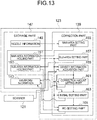
- a recording apparatus includes a head and a control part which controls the head.
- the head includes a facing surface which faces a recording medium and includes a plurality of recording elements which are mutually different in positions in a predetermined direction along the facing surface and individually form a plurality of dots configuring an image on the recording medium.
- the control part includes a correction part which corrects signal information prescribing driving signals to be individually input to the plurality of recording elements.
- the correction part includes a main area information holding part, sub-area information holding part, initial setting part, and re-setting part.
- the main area information holding part holds information prescribing a plurality of main areas obtained by dividing at least a portion of the facing surface into a plurality of areas in the predetermined direction.
- Each main area includes two or more recording elements belonging to it.
- the sub-area information holding part holds information prescribing a plurality of sub-areas obtained by dividing a main area into a plurality of areas in the predetermined direction for at least one of the plurality of main areas.
- Each sub-area includes two or more recording elements belonging to it.
- the initial setting part designates settings relating to correction including presence of any corrections in units of the main areas.
- the re-setting part maintains or redesignates the settings relating to correction which are designated with respect to the first main area in units of sub-areas .
- the re-setting part redesignates a setting for a sub-area in the first main area which adjoins the second main area to obtain a correction amount between the correction amount of its original setting and the correction amount of the second main area.
- a program for a recording apparatus is a program making a computer connected to the head function as the control part.
- FIG. 1A is a schematic side view of a recording apparatus of a color inkjet printer 1 (below, sometimes simply referred to as a "printer") including liquid ejection heads 2 (below, sometimes simply referred to as "heads") according to an embodiment of the present disclosure.
- FIG. 1B is a schematic plan view of the printer 1.
- the printer 1 makes a recording medium of printing paper P move relative to the heads 2 by conveying the printing paper P from a paper feed roller 80A to a collection roller 80B.
- the paper feed roller 80A and collection roller 80B and the various types of rollers which will be explained later configure a movement part 85 which makes the printing paper P and the head 2 relatively move with respect to each other.
- the control device 88 controls the heads 2 based on images, text, and other data of printing data etc. to make the heads 2 eject liquid toward the printing paper P and make liquid droplets land onto the printing paper P to thereby perform printing or other recording on the printing paper P.
- the heads 2 are fixed with respect to the printer 1, so the printer 1 becomes a so-called "line printer”.
- a so-called “serial printer” which alternately performs an operation of moving the heads 2 so that they reciprocally move in a direction intersecting the conveyance direction of the printing paper P, for example, an almost perpendicular direction, and eject the liquid droplets in the middle of the movement and conveyance of the printing paper P.
- each frame 70 is provided with not shown five holes.
- Five heads 2 are respectively mounted in the hole portions.
- the five heads 2 mounted on one frame 70 configure one head group 72.
- the printer 1 has four head groups 72, so 20 heads 2 in total are mounted.
- Each head 2 mounted on a frame 70 is designed so that the portion ejecting the liquid faces the printing paper P.
- a distance between the head 2 and the printing paper P is made for example about 0.5 to 20 mm.
- the 20 heads 2 may be directly linked with the control device 88 or may be connected through a distribution part distributing the printing data interposed between the two.
- the control device 88 may send the printing data to one distribution part, and the one distribution part may distribute the printing data to the 20 heads 2.
- the control device 88 may distribute the printed data to four distribution parts corresponding to the four head groups 72, and each distribution part may distribute the printing data to the five heads 2 in the corresponding head group 72.
- the heads 2 have elongated shapes in directions from the front side toward the deep portion in FIG. 1A and in the vertical direction in FIG. 1B .
- three heads 2 are arranged along a direction intersecting the conveyance direction of the printing paper P, for example, an almost perpendicular direction, and the other two heads 2 are arranged one by one between each two heads 2 among the three heads 2 at positions offset along the conveyance direction.
- the heads 2 are arranged in a zigzag manner.
- the heads 2 are arranged so that the ranges which can be printed by the heads 2 are linked in a width direction of the printing paper P, that is, the direction intersecting the conveyance direction of the printing paper P, or so that the ends overlap, therefore printing without a clearance in the width direction of the printing paper P becomes possible.
- the four head groups 72 are arranged along the conveyance direction of the printing paper P.
- Each head 2 is supplied with a liquid, for example, ink, from a not shown liquid supply tank.
- the heads 2 belonging to one head group 72 are supplied with ink having the same color.
- Inks of four colors can be printed with by the four head groups 72.
- the colors of the ink ejected from the head groups 72 are for example magenta (M), yellow (Y), cyan (C) , and black (K) . If such inks is printed by controlling of the control device 88, a color image can be printed.
- the number of heads 2 mounted in the printer 1 may be one as well so far as the printing is carried out by one color in a range where printing by one head 2 is possible.
- the number of the heads 2 included in the head groups 72 and the number of the head groups 72 can be suitably changed according to the object for printing or the printing conditions. For example, in order to perform further multi-color printing, the number of the head groups 72 may be increased as well. Further, if a plurality of head groups 72 performing printing in the same color are arranged and the printing is alternately carried out in the conveyance direction, even if the heads 2 having the same performances are used, the conveyance speed can be made faster. Due to this, the printing area per time can be made larger. Further, a plurality of head groups 72 performing printing in the same color may be prepared and arranged offset in the direction intersecting with the conveyance direction to thereby raise the resolution in the width direction of the printing paper P.
- printing may be carried out by the heads 2 by a coating agent or other liquid uniformly or by patterning in order to treat the surface of the printing paper P.
- a coating agent for example, when using as the recording medium one into which the liquid has a hard time impregnating, use can be made of an agent forming a liquid receiving layer so that the liquid is easily fixed. Otherwise, as the coating agent, when use is made of a recording medium into which the liquid is easily impregnated, use can be made of an agent forming a liquid permeation suppression layer so as to prevent a liquid from bleeding too much or prevent the liquid from mixing with another liquid which impacts the vicinity too much.
- the coating agent may be uniformly coated by a coating machine 76 controlled by the control device 88 other than the printing by the heads 2 as well.
- the printer 1 performs printing on the recording medium of the printing paper P.
- the printing paper P is in a state wound around the paper feed roller 80A.
- the printing paper P sent out from the paper feed roller 80A passes the lower side of the heads 2 mounted in the frame 70, then passes between the two conveyance rollers 82C, and is finally collected by the collection roller 80B.
- the printing paper P is conveyed at a constant velocity and is printed by the heads 2.
- the printing paper P sent out from the paper feed roller 80A passes between two guide rollers 82A and then passes under the coating machine 76.
- the coating machine 76 coats the coating agent explained above on the printing paper P.
- the printing paper P enters into a head chamber 74 accommodating the frames 70 in which the heads 2 are mounted.
- the head chamber 74 is linked with the external portion in portions such as parts where the printing paper P enters and exits.
- the head chamber 74 is substantially a space isolated from the external portion.
- the head chamber 74 is controlled in control factors such as temperature, humidity, atmospheric pressure, etc. by the control device 88 or the like.
- the control device 88 is controlled in control factors such as temperature, humidity, atmospheric pressure, etc.
- the printing paper P is conveyed over the guide rollers 82B.
- the five guide rollers 82B are arranged so as to project at the centers toward the direction in which the frames 70 are arranged when viewed from the side. Due to this, the printing paper P conveyed over the five guide rollers 82B becomes arc shaped when viewed from the side. Therefore, by applying tensile force to the printing paper P, the printing paper P between each two guide rollers 82B is stretched so as to become planar shaped.
- one frame 70 is arranged between the two guide rollers 82B. The frames 70 are changed little by little in the set angles so as to become parallel to the printing paper P which is conveyed under them.
- the printing paper P which exits the head chamber 74 passes between the two conveyance rollers 82C, passes through the interior of a drying machine 78, passes between the two guide rollers 82D, and is collected by the collection roller 80B.
- the conveyance rate of the printing paper P is made for example 100 m/min.
- Each roller may be controlled by the control device 88 or may be manually operated by a human worker.
- the dryings may be carried out in order by a plurality of drying methods or the drying may be carried out by using a plurality of drying methods together. As the drying method used at that time, for example, there are blowing of hot air, emission of infrared rays, contact with a heated roller, and the like.
- infrared rays when infrared rays are emitted, infrared rays in a special frequency range may be emitted so as to reduce damage to the printing paper P while making the drying faster.
- the time of transfer of heat may be made longer as well by conveying the printing paper P along the cylindrical surface of the roller.
- the range where the paper is conveyed along the cylindrical surface of the roller is preferably a 1/4 turn of the cylindrical surface of the roller. Further, preferably, it is made a 1/2 turn or more of the cylindrical surface of the roller.
- a UV light source may be arranged as well.
- the UV light source may be arranged between each two frames 70 as well.
- the printer 1 may be provided with a cleaning part cleaning the heads 2 as well.
- the cleaning part for example performs wiping or cleaning by capping. Wiping for example wipes the surface of the portion to which the liquid is ejected, for example, the facing surface 2a (explained later), by a wiper having flexibility to thereby remove the liquid deposited on the surface.
- the cleaning by capping is for example carried out in the following way. First, a cap is placed so as to cover the portion to which the liquid is ejected, for example the facing surface 2a (this will be referred to as "capping") to thereby form a space which is substantially sealed by the facing surface 2a and the cap.
- the recording medium may be a rolled textile or the like as well other than the printing paper P. Further, in place of direct conveyance of the printing paper P, the printer 1 may directly run a conveyance belt and place the recording medium on the conveyance belt to convey the same. When performing conveyance in this way, a sheet, cut textile, wood, tile, and the like can be used as the recording media as well. Further, wiring patterns etc. of an electronic apparatus may be printed by ejecting a liquid containing conductive particles from the heads 2 as well. Furthermore, it is possible to eject a predetermined amount of liquid chemical agent or liquid containing a chemical from the heads 2 toward a reaction vessel or the like to cause a reaction and the like to prepare a chemical or pharmaceutical.
- the control device 88 may control the parts in the printer 1 in accordance with the states of the parts in the printer 1 which are seen from the information from the sensors. For example, in a case where the temperature of the heads 2, the temperature of the liquid in the liquid supply tank for supplying the liquid to the heads 2, the pressure applied to the heads 2 by the liquid in the liquid supply tank, and the like exert an influence upon the ejection characteristics of the liquid ejected, that is, the ejection amount, ejection speed, and the like, the driving signal for ejecting the liquid may be changed in accordance with those information as well.
- FIG. 2A is a plan view showing the facing surface 2a in a head 2 which faces the recording medium.
- FIG. 2B is an enlarged view of a region IIb in FIG. 2A .
- an orthogonal coordinate system comprised of a D1 axis, D2 axis, D3 axis, etc. is attached.
- the D1 axis is defined to be parallel to a direction of relative movement of the head 2 and the recording medium.
- the relationships between positive/negative of the D1 axis and the advancing direction of the recording medium relative to the head 2 do not particularly matter in the explanation of the present embodiment.
- the D2 axis is defined so as to be parallel to the facing surface 2a and the recording medium and perpendicular to the D1 axis.
- the D3 axis is defined so as to be perpendicular to the facing surface 2a and the recording medium.
- the -D3 side (front side on the drawing sheets in FIG. 2A and FIG. 2B ) is made a direction from the head 2 toward the recording medium. In the head 2, any direction may be used as “above” or “below”. For convenience, sometimes use will be made of terms such as the "lower surface” using the +D3 side as above.
- the facing surface 2a is provided with a plurality of nozzles 3 ejecting ink droplets.
- the plurality of nozzles 3 are arranged while making their positions in the D2 direction different from each other. Accordingly, by relatively moving the head 2 and the recording medium in the D1 direction by the movement part 85 while ejecting the ink droplets from the plurality of nozzles 3, any two-dimensional image may be formed.
- the plurality of nozzles 3 are arranged in a plurality of rows (eight rows in the example shown) . That is, a plurality of nozzle rows 5A to 5H (hereinafter, sometimes A to H will be omitted) are configured by the plurality of nozzles 3. Each nozzle 3 corresponds to one dot on the recording medium. Note that, in FIG. 2A , the nozzle rows 5 are shown by straight lines since the nozzles 3 are very small relative to the facing surface 2a. Further, in the enlarged view of FIG. 2B , the nozzles 3 are drawn larger than the actual ones (drawn larger relative to the pitch).
- the plurality of nozzle rows 5 are for example substantially parallel to each other. Further, they have equal lengths to each other. In the example shown, the nozzle rows 5 are inclined relative to the D2 direction. In FIG. 2A and FIG. 2B , a D5 axis which is substantially parallel to the nozzle rows 5 and a D4 axis which is perpendicular to the D5 axis are attached.
- the inclination angle ⁇ 1 of the nozzle rows 5 relative to the D2 axis may be suitably set. Note that, such an inclination need not be provided either.
- the sizes of the intervals among the plurality of nozzle rows 5 are not equal.
- the plurality of intervals are made the same size for every other row.
- Such a configuration is for example caused for convenience of arrangement of the channels inside the heads 2.
- the sizes of the plurality of intervals may be made equal as well.
- each nozzle row 5 a relatively large number of nozzles 3 are provided.
- the number of the nozzles 3 in each nozzle row 5 is at least larger than the number of the nozzle rows 5 (number of rows) .
- the number of the nozzles 3 in each nozzle row 5 may be suitably set. Giving one example, it is 500 to 1000.
- each nozzle row 5 the plurality of nozzles 3 are linearly arranged. Further, in each nozzle row 5, the pitch of the plurality of nozzles 3 is constant in the D5 (D2) direction. Further, the pitch is the same among the plurality of nozzle rows 5. However, for example, in each nozzle row 5, the plurality of nozzles 3 may be offset (varied) from the positions of constant pitch on the line by a relatively very small amount (for example an amount smaller than the pitch) in the direction of extension of the line or a direction crossing the line. Further, such an offset may be different among the plurality of nozzle rows 5 as well.
- FIG. 3 is a schematic view for explaining the relationships among the plurality of nozzle rows 5. Note that, the nozzles 3 in the nozzle row 5C, unlike the other nozzles 3, are indicated by black circles. However, this is only for easier explanation.
- the nozzles 3 in the plurality of nozzle rows 5 are projected in the D1 direction (direction of relative movement of the head 2 and the recording medium) onto a line L1 which is parallel to the D2 direction, the plurality of nozzles 3 are arranged in a sequence by which the nozzles 3 in the same nozzle row 5 are not successive.
- the nozzles 3 in the plurality of nozzle rows 5 are arranged on the line L1 in the constant orders assigned to the plurality of nozzle rows 5. That is, in a range NP including the same number of positions DP of the nozzles 3 on the line L1 as the number of the nozzle rows 5, one each of the nozzles 3 in the nozzle rows 5 are included.
- the sequence of the nozzle rows 5 within the range NP is the same among the plurality of ranges NP. However, it is also possible to make the sequence of the nozzle rows 5 in the positions DP on the line L1 not constant.
- the pitch of the positions DP is for example constant. However, the pitch of the positions DP may fluctuate by a very small amount (amount smaller than the pitch) as well.
- the dot density on the line L1 becomes “n” times the dot density in each nozzle row 5.
- the dot density may be suitably set.
- the dot density in the D2 direction in each nozzle row 5 is 100 dpi to 200 dpi while the dot density in the D2 direction realized by the eight nozzle rows 5 is 800 dpi to 1600 dpi.
- nozzle columns 6 which substantially linearly extend in directions intersecting the D5 axis are configured by the plurality of nozzles 3.
- the above two types of arrangement orders may be different from each other as well.
- the linear shaped nozzle columns 6 need not be configured either.
- FIG. 4 is a schematic cross-sectional view showing a portion of a head 2 in an enlarged manner. Note that, the lower part on the drawing sheet in FIG. 4 is the side facing the recording medium (-D3 side).
- the head 2 is a piezo type head giving pressure to the ink by mechanical distortion of piezoelectric elements.
- the head 2 has a plurality of ejection elements 11 individually provided for the nozzles 3.
- FIG. 4 shows one ejection element 11.
- the orientations and number of the ejection elements 11 in each row may be suitably set together with design of the route of a common channel 19 which will be explained later and the like.
- the ejection elements 11 may have the same orientations as each other or may alternately have inverse orientations.
- one row of the ejection elements 11 may be provided with respect to one nozzle row 5, or two rows of the ejection elements 11 may be provided at the two sides of one nozzle row 5 in inverse orientations to each other.
- Two rows of ejection elements 11 corresponding to two mutually adjoining nozzle rows 5 may be configured as if they were one row by alternate arrangement of each of the ejection elements 11 in the two rows.
- the head 2 from another viewpoint, has channel members 13 forming spaces for storing the ink and actuators 15 which give pressure to the ink stored in the channel members 13.
- the plurality of ejection elements 11 are configured by the channel members 13 and actuators 15.
- a plurality of individual channels 17 (one is shown in FIG. 4 ) and a common channel 19 communicated with the plurality of individual channels 17 are formed.
- the individual channel 17 is provided for each ejection element 11, and the common channel 19 is provided common to the plurality of ejection elements 11.
- Each individual channel 17 has the already explained nozzle 3, a partial channel 21 having a bottom surface 21a in which the nozzle 3 opens, a pressurizing chamber 23 communicated with the partial channel 21, and a communication path 25 communicating the pressurizing chamber 23 and the common channel 19 with each other.
- the plurality of individual channels 17 and common channel 19 are filled with ink.
- the ink is sent out from the pressurizing chamber 23 to the partial channel 21 and ink droplets are ejected from the nozzle 3. Further, the pressurizing chamber 23 is refilled with ink from the common channel 19 through the communication path 25.
- the cross-sectional shapes or planar shapes of the plurality of individual channels 17 and common channel 19 may be suitably set.
- the configurations of the plurality of individual channels 17 (orientations when viewed on a plane are excluded) are for example substantially the same as each other. However, the inclination of the partial channel 21 and other parts may be different from each other as well.
- the pressurizing chamber 23 is for example formed to a constant thickness in the D3 direction. Further, when viewed on a plane, it is made substantially diamond shaped or elliptical or the like. An end part of the pressurizing chamber 23 in the plane direction is communicated with the partial channel 21, and the end part on the opposite side is communicated with the communication path 25. A portion of the communication path 25 is made a constricted portion smaller in cross-sectional area perpendicular to the direction of flow than the areas of the common channel 19 and pressurizing chamber 23.
- the partial channel 21 extends from the bottom surface (surface on the -D3 side) of the pressurizing chamber 23 to the facing surface 2a side.
- the shape of the cross-section (cross-section perpendicular to the D3 axis) of the partial channel 21 may be suitably set. Although not particularly shown, for example, it is circular or rectangular. Further, the cross-sectional shape (including dimensions) may be constant over the length (substantially the D3 direction) of the partial channel 21 or may change. In the example shown, it somewhat changes.
- the partial channel 21 may extend parallel to the D3 axis or may extend with a suitable inclination relative to the D3 axis.
- the nozzle 3 opens at the bottom surface 21a of the partial channel 21 with a smaller area than the bottom surface 21a.
- the shape of the nozzle 3 may be suitably set.
- the nozzle 3 is circular when viewed on a plane and becomes smaller in diameter the more to the facing surface 2a side. That is, the shape of the nozzle 3 is substantially a truncated cone shape.
- the nozzle 3 may be configured so that a portion on the front end side (-D3 side) increases in diameter the more to the front end side as well.
- the common channel 19 for example extends along the facing surface 2a below the pressurizing chamber 23. Although not particularly shown, for example, the common channel 19 is configured so as to branch in a manifold manner.
- the branched portions for example extend along the nozzle rows 5. In a case where the nozzle columns 6 are configured etc., the above branched portions may extend along the nozzle columns 6 in place of the nozzle rows 5 as well.
- the channel member 13 is for example configured by a plurality of plates 27A to 27J (below, sometimes A to J will be omitted) stacked on each other.
- the plates 27 via holes and/or recessed portions configuring the plurality of individual channels 17 and common channel 19 are formed.
- the thicknesses and stacked number of the plurality of plates 27 may be suitably set in accordance with the shapes etc. of the plurality of individual channels 17 and common channel 19.
- the plurality of plates 27 may be formed by suitable materials. For example, they are formed by metal, resin, ceramic, or silicon.
- the plate 27 which is positioned closest to the -D3 side among the plurality of plates 27 will be sometimes referred to as the "nozzle plate 27A".
- the nozzle plate 27A for example configures the facing surface 2a by its lower surface and configures the bottom surface 21a of the partial channel 21 by its upper surface.
- the nozzles 3 are configured by holes penetrating through the nozzle plate 27A in its thickness direction.
- the actuator 15 is for example configured by a unimorph type piezoelectric element which displaces in a flexural mode.
- the actuator 15 has a vibration plate 29, common electrode 31, piezoelectric body 33, and a plurality of individual electrodes 35 stacked in order from the pressurizing chamber 23 side.
- the vibration plate 29, common electrode 31, and piezoelectric body 33 are for example provided common to the plurality of pressurizing chambers 23 (plurality of ejection elements 11) so as to cover the plurality of pressurizing chambers 23.
- an individual electrode 35 is provided for each pressurizing chamber 23 (ejection element 11) .
- a part corresponding to one ejection element 11 will be sometimes referred to as a "pressurization element 37".
- the configurations of the plurality of pressurization elements 37 (orientations when viewed on a plane are excluded) are the same as each other.
- the vibration plate 29, closes the upper surface opening of each pressurizing chamber 23 by superposition on the upper surface of the channel member 13.
- the pressurizing chamber 23 may be closed in the upper surface opening by the plate 27 and the vibration plate 29 superimposed on it.
- plate 27 may be grasped as a portion of the vibration plate, and the pressurizing chamber 23 may be grasped as being closed by the vibration plate.
- the piezoelectric body 33 has the thickness direction (D3 direction) as its polarization direction. Accordingly, for example, when voltage is supplied to the common electrode 31 and individual electrodes 35 and an electric field is made act with respect to the piezoelectric body 33 in the polarization direction, the piezoelectric body 33 contracts in the plane (in the plane perpendicular to the D3 axis) . By this contraction, the vibration plate 29 flexes so as to project to the pressurizing chamber 23 side. As a result, the volume of the pressurizing chamber 23 changes .
- the common electrode 31 extends over the plurality of pressurizing chambers 23 as already explained and is given a constant potential (for example a reference potential).
- Each individual electrode 35 includes an individual electrode body 35a positioned on the pressurizing chamber 23 and a lead-out electrode 35b led out from that individual electrode body 35a.
- the shape and size of the individual electrode body 35a are substantially equal to the pressurizing chamber 23.
- the vibration plate 29, common electrode 31, piezoelectric body 33, and individual electrodes 35 may be formed by suitable materials .
- the vibration plate 29 is formed by ceramic, silicon oxide, or silicon nitride.
- the common electrode 31 and individual electrodes 35 are for example formed by platinum or palladium.
- the piezoelectric body 33 is for example formed by PZT (lead zirconate titanate) or another ceramic.
- the actuator 15 for example, although not particularly shown, is connected with a flexible printed circuit board (FPC) which is arranged facing the actuator 15. Specifically, the lead-out electrodes 35b are connected, and the common electrode 31 is connected through a not shown via conductor or the like. Further, the control device 88, for example, gives a constant potential to the common electrode 31 and individually inputs driving signals to the plurality of individual electrodes 35 through a not shown driving IC (integrated circuit) mounted in the FPC.
- FPC flexible printed circuit board
- the driving signals are supplied in a constant cycle synchronized with the conveyance speed of the printing paper P.
- the waveform of the driving signals may be made waveforms of various known types.
- a driving signal for so-called pull-push will be explained.
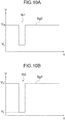
- FIG. 10A is a schematic view showing an example of the waveform of a driving signal Sg1.
- an abscissa shows the time "t”
- an ordinate shows a potential V of the driving signal Sg1.
- the driving signal Sg1 (from another viewpoint, the individual electrode 35) is rendered a potential higher than the common electrode 31 (below, referred to as a "high potential V H ") . Further, whenever an ejection request is issued, the potential of the individual electrode 35 is rendered a lower potential than the high potential V H (below, called a "low potentials V L ”) and then rendered the high potential V H again at a predetermined timing.
- the low potential V L may be suitably set. For example, it is the same potential as that of the common electrode 31.
- the actuator 15 Before the ejection request, the actuator 15 is shaped flexing to the pressurizing chamber 23 side due to the driving signal Sg1 being rendered the high potential V H .
- the actuator 15 returns (begins to return) to the original (flat) shape, therefore the volume of the pressurizing chamber 23 increases. In turn, a negative pressure is given to the liquid in the pressurizing chamber 23. This being so, the liquid in the pressurizing chamber 23 begins to vibrate by a natural vibration period. Next, the volume of the pressurizing chamber 23 becomes the maximum and the pressure becomes substantially zero. Further, the volume of the pressurizing chamber 23 begins to decrease and the pressure becomes higher.
- the actuator 15 By the driving signal Sg1 being rendered the low potential V L and then becoming the high potential V H , the actuator 15 begins to flex to the pressurizing chamber 23 side again. The vibration which was applied first and the vibration which was applied next overlap, therefore a larger pressure is applied to the liquid. This pressure is propagated in the partial channel 21 and thereby makes the nozzle 3 eject the liquid.
- the pulse width in actuality is made a value of about 0.5 AL to 1.5 AL since there are other factors to be considered as well such as ejected liquid droplets being gathered into one. Further, the ejection amount can be reduced by the pulse width being controlled to a value out of AL, therefore the pulse width is made a value out of the AL in order to reduce the ejection amount.
- the darkness intended in the image (including text as well) formed on the recording medium may be realized by a suitable method.
- it may be realized by the sizes of the dots on the recording medium, may be realized by a change of the number of dots per constant area (rough/fine) , or these may be combined.
- the sizes of the dots may be adjusted by the size of one liquid droplet, may be adjusted by the number of the liquid droplets deposited onto one position, or these may be combined.
- the intended darkness may be realized by the size of the liquid droplets ejected from the nozzles 3 adjusted according to the potential difference between the high potential V H and the low potential V L of the driving signal Sg1 or the like, may be realized by change of the number of the liquid droplets adjusted according to the wave number included in the driving signal Sg1 corresponding to one time' s worth of ejection request, may be realized by change of the number of the ejection elements 11 performing the ejection operation per constant area, or these may be combined.
- the ejection characteristics vary among the plurality of ejection elements 11. For example, even if formation of dots having the same size on the recording medium is intended, a difference arises in sizes of the dots among the plurality of ejection elements 11. As the reason for that, for example, there can be mentioned manufacturing tolerances of the nozzles 3, differences of the positions of the individual channels 17 relative to the common channel 19, and variations of potentials of the driving signals Sg1. Further, such differences of features of the dots for example appear as unintended uneven print darkness.
- the correction amount must be calculated and the correction amount must be stored for each ejection element 11, therefore the processing load increases, and/or the amount of the memory used increases.
- the facing surface 2a of the head 2 is divided into a plurality of areas in a predetermined direction (D2 direction in the example shown) to set a plurality of main areas 101. Further, settings relating to correction are designated in units of the main areas 101. By doing this, the processing load is lightened and/or the amount of the memory used can be reduced.
- the settings relating to correction mean for example settings of presence of any corrections and settings of the correction amounts.
- "designating the settings relating to correction” may be for example storing information showing presence of any corrections and correction amounts (for example, values of variables showing presence of any corrections and correction amounts) in the storage part.
- the later explained “maintaining and redesignating the settings” may be for example maintaining or update of such information stored in the storage part.
- settings of presence of any corrections may be grasped as settings of whether the correction amount is to be made 0 and may be included in the concept of settings of the correction amounts.
- the explanation of the present embodiment is predicated on differentiation of the settings of presence of any corrections and the settings of the correction amounts. However, sometimes the two will not be differentiated.
- correction is not carried out or the correction amount is 0, in both cases, in the computer or the like, processing which is different from the processing in the case where correction is carried out may be carried out or the same processing as the processing in the case where correction is carried out but where the value of the variable corresponding to the correction amount is made 0 may be carried out.
- the settings relating to correction in units of the main areas 101 there can be mentioned a mode of designating settings relating to the mutually same corrections for the plurality of ejection elements 11 included in each main area 101.
- a mode of setting for a main area 101 a ratio between the ejection elements 11 to be corrected and the ejection elements 11 not to be corrected in the plurality of ejection elements 11 in the main area 101 and assigning presence of any corrections to the plurality of ejection elements 11 based on this ratio.
- the ratio explained above is not a parameter able to be individually set for the plurality of ejection elements 11, therefore setting a ratio may be said to be designating settings relating to corrections in units of the main areas 101. Further, from another viewpoint, setting a ratio is not setting presence of any corrections for the plurality of ejection elements 11 in accordance with the individual characteristics of the plurality of ejection elements 11, therefore it may be said to be designating settings relating to corrections in units of the main areas 101. The same is true for the settings relating to corrections in units of sub-areas 103 which will be explained later.
- FIG. 5A and FIG. 5B are graphs explaining the difference of darkness which occurs in a case of designating settings relating to corrections in units of the main areas 101.
- the abscissas show the positions in the D2 (D5) direction.
- N is an integer of 1 or more main areas 101 is plotted.
- the ordinates show density values.
- the density values are for example OD (optical density) values.
- the density value is corrected so as to raise the density value in the N-th main area 101 having the lowest density value. Due to this, the difference dOD2 between the minimum value and the maximum value of the density values becomes smaller than the difference dOD1 of density values in FIG. 5A . That is, the unintended darkness is reduced.
- a main area 101 having a relatively low density value was made higher in density value.
- a main area 101 having a relatively high density value may be corrected lower the density value as well.
- basically the former will be explained as an example.
- the explanation of the present embodiment may be employed by reading the high and low values reversely, so the explanation will be omitted.
- FIG. 6 is a view similar to FIG. 5A and FIG. 5B for explaining a method of reducing differences of darkness at the boundaries among the main areas 101 explained above.
- At least one (two in the example shown) of the main areas 101 which are different from each other in settings relating to corrections and adjoin each other is divided into a plurality of sub-areas 103 (103A and 103B) . Further, maintaining or redesignating the settings relating to corrections designated for the main area 101 is carried out in units of the sub-areas 103.
- the maintaining or redesignating the settings relating to corrections in units of the sub-areas 103 is carried out so that the correction amounts of darkness of two main areas 101 which adjoin each other become closer to each other near the boundary of the two. Due to this, the difference of darkness at the boundary of mutually adjoining main areas 101 is reduced, therefore the probability that the difference of darkness will be visually perceived as a stripe can be lowered. Further, since the settings relating to corrections are designated in units of the sub-areas 103, an increase of the processing load and increase of the amount of the memory used are suppressed.
- the N+1-th main area 101 was set for no correction ( FIG. 5B ).
- the sub-area 103 adjacent to the N-th main area 101 is redesignated in settings relating to corrections so that its correction amount becomes a value between the correction amount of the original settings (zero) and the correction amount of the N-th main area 101 (not limited to exactly the middle, the same is true for the following explanation).
- all sub-areas 103 in the N+1-th main area 101 are redesignated in settings relating to corrections so that the correction amounts become closer to the correction amount of the N-th main area 101 the closer the sub-area 103 to the N-th main area 101.
- the N-th main area 101 was set so that the correction was to be carried out ( FIG. 5B ) .
- the sub-area 103A in the N-th main area 101 which adjoins the N+1 main area 101 is redesignated in settings so that its correction amount becomes an amount between the correction amount of the original settings and the correction amount of the N+1-th main area (in more detail, the correction amount after the redesignation in the sub-area 103 adjoining the N-th main area 101) .
- the remaining sub-area 103B is maintained in the original settings relating to corrections.
- the settings relating to corrections are redesignated so that the density value of the N+1-th main area 101 which generated the minimum value of the density value in FIG. 5B becomes larger.
- the secondary effect arises that a difference dOD3 between the minimum value and the maximum value of the density values in FIG. 6 becomes smaller than the difference dOD2 in FIG. 5B .
- FIG. 7 to FIG. 9 are schematic views showing examples of patterns of settings relating to corrections of the sub-areas. These views show the three N-th to N+2-th main areas 101. Hatchings attached to the main areas 101 or sub-areas 103 show settings relating to corrections. Specifically, no hatching shows no correction while denser hatchings show larger correction amounts.
- the numerical values (%) in the figures will be explained in detail later, but here they should be understand as follows.
- "0%" in the upper rows shows that correction is not carried out.
- "100%” in the upper rows shows the correction amounts (not zero) which are set first for the main areas 101. Note that, as already explained, in the present embodiment, these correction amounts are the same as each other among the plurality of main areas 101 for which settings of carrying out corrections were designated.
- the numerical values in the upper rows which exceed 0% and are less than 100% show the ratios of the correction amounts in settings which are redesignated for the sub-areas 103 relative to the above 100% of correction amount.
- the numerical values in the lower rows are values obtained by subtracting the numerical values in the upper rows from 100%.
- the settings relating to corrections first designated in units of main areas 101 will be referred to as the "initial settings”.
- the main areas 101 which are set so be corrected in the initial settings will be sometimes referred to as the "correction areas 101A" .
- the main areas 101 which are set so as not to be corrected in the initial settings will be sometimes referred to as the "non-correction areas 101B".
- the example in FIG. 7 corresponds to the example shown in FIG. 6 .
- the N-th main area 101 is a correction area 101A
- the N+1-th and N+2-th main areas 101 are non-correction areas 101B.
- the left side of the N-th main area 101 on the page there is no main area 101 or there is a correction area 101A.
- the right side of the N+2-th main area 101 on the page there is no main area 101 or there is a non-correction area 101B.
- the sub-areas 103 adjoining the N+1-th main area 101, the sub-areas 103A adjoining the N+1-th main area 101 are redesignated in settings relating to corrections so that the correction amounts become smaller (become closer to the correction amount of the N+1-th main area 101).
- the initial settings are maintained.
- a correction area 101A may also be maintained in initial settings without being redesignated in settings relating to corrections for the sub-areas 103.
- a non-correction area 101B (N+1) for which the settings relating to corrections are redesignated the part of the sub-areas 103 on the other non-correction area 101B (N+2) side may be maintained in the initial settings (no corrections) without redesignation of the settings relating to corrections. The same is true for the other examples of patterns which will be explained later.
- examples of patterns inverted left and right from FIG. 7 may also be generated.
- the left and right inverted patterns may be handled as different patterns as well.
- the N-th and N+2-th main areas 101 are non-correction areas 101B and the N+1-th main area 101 between the two is a correction area 101A.
- the N-th main area 101 on the page there is no main area 101 or there is a non-correction area 101B.
- the right side of the N+2-th main area 101 on the page there is no main area 101 or there is a non-correction area 101B.
- the settings relating to corrections are redesignated. Further, in the N-th main area 101, the settings relating to corrections are redesignated by a pattern inverted left and right from the pattern of the N+1-th main area 101 in FIG. 7 .
- the sub-areas 103A adjoining the non-correction areas 101B are redesignated in settings relating to corrections so that the correction amounts become smaller (so as to approach the correction amounts of the non-correction areas 101B) .
- the non-correction areas 101B adjoin the N+1-th main area 101 at the two sides, therefore the settings relating to corrections are redesignated in the sub-areas 103A at the two sides, and the initial settings are maintained in the sub-area 103C which remains at the center.
- the N-th and N+2-th main areas 101 are correction areas 101A and the N+1-th main area 101 between the two is a non-correction area 101B.
- the N-th main area 101 on the page there is no main area 101 or there is a correction area 101A.
- the right side of the N+2-th main area 101 on the page there is no main area 101 or there is a correction area 101A.
- the sub-areas 103A adjoining the non-correction area 101B (N+1-th main area 101) are redesignated in settings relating to corrections so that the correction amounts become smaller (so as to approach the correction amount of the N+1-th main area 101).
- non-correction areas 101B an area like the N+1-th main area 101 in FIG. 7 for which the settings relating to corrections are redesignated so that the correction amounts of the sub-areas 103 gradually become larger from one side (the other non-correction area 101B side) toward the other side (the correction area 101A side) will be sometimes referred to as a "first diffusion area 101D" .
- a non-correction area 101B like the N+1-th main area 101 in FIG. 9 in which the correction amounts of the sub-areas 103 gradually become larger from the center side toward the two sides (sides of the correction areas 101A) will be sometimes referred to as a "second diffusion area 101E".
- a non-correction area 101B like the N+2-th main area 101 in FIG. 7 for which the initial settings are maintained will be sometimes referred to as a "true non-correction area 101F”.
- this non-correction area 101B is defined as a first diffusion area 101D when only one side adjoins a correction area 101A and is defined as a second diffusion area 101E when adjoining correction areas 101A at the two sides.
- one sub-area 103A adjoining the non-correction area 101B is redesignated in settings relating to corrections so that the correction amount becomes smaller. Further, in this correction area 101A, one sub-area 103A is redesignated in settings relating to corrections when only one side adjoins a non-correction area 101B, while two sub-areas 103A are redesignated in settings relating to corrections when two sides adjoin non-correction areas 101B. Further, the remaining sub-areas 103 (103B or 103C) are maintained in the initial settings.
- main areas 101 other than those described above are maintained in the initial settings.
- the "main areas 101 other than those explained above” are specifically a correction area 101A adjoining correction areas 101A at its two sides (sometimes there is no main area 101 on one side) and a non-correction area 101B (true non-correction area 101F) adjoining non-correction areas 101B at its two sides (sometimes there is no main area 101 on one side).
- Examples of patterns generated by the method of redesignation of settings relating to corrections explained above are generated in cases other than FIG. 7 to FIG. 9 as well.
- a pattern where not first diffusion areas 101D, but second diffusion areas 101E are positioned on the two sides of the N+1-th main area 101 in FIG. 8 may be generated as well.
- these can be deduced from the explanations up to here, therefore illustration is omitted.
- the main areas 101 may be suitably set with respect to the facing surface 2a of the head 2 (in more detail, the region where the nozzles 3 are arranged).
- the direction dividing the facing surface 2a into a plurality of main areas 101 may be the D2 direction as shown in FIG. 2 (the direction perpendicular to the direction in which the recording medium and the head relatively move) or may be another direction (for example the D5 direction, D1 direction, or D4 direction) unlike FIG. 2 .
- the facing surface 2a may be divided into a plurality of areas in the both of the D5 direction and D4 direction or otherwise divided two-dimensionally. Further, it is also possible to form the boundaries of the main areas 101 in intertwined shapes.
- the sizes of the main areas 101 may be suitably set as well.
- the sizes of the plurality of main areas 101 may be the same as each other or may be different from each other.
- the main areas 101 other than the main areas 101 at the two ends are given mutually the same sizes.
- the main areas 101 at the two ends are made smaller than the other main areas 101.
- the end parts are parts which easily become abnormal regions concerning the ejection characteristics of the nozzles 3 and the like. Therefore, if the main areas 101 in the end parts are made smaller, it becomes easier to adjust the densities by a high precision.
- all main areas 101 may have mutually the same sizes as well.
- the specific sizes of the main areas 101 may also be suitably set. For example, if the number of the nozzles 3 included in a main area 101 is large, the effects (lightening of the processing load and the like) due to designation of the settings relating to corrections in units of the main areas 101 are improved. On the other hand, if the number of the nozzles 3 included in a main area 101 is small, for example, the accuracy of the correction is improved. Accordingly, the sizes of the main areas 101 may be suitably set by comparing and considering the two. When explaining one example, the number of the nozzles 3 included in one main area 101 or the number of the positions DP in FIG. 3 is 100 to 500. Further, when explaining one example from another viewpoint, the number of the plurality of main areas 101 (number of areas the facing surface 2a of the head 2 is divided into) is 10 to 40.
- the arrangement of the nozzles 3 and the arrangement of the pressurization elements 37 do not always coincide. Accordingly, for example, in the vicinity of the boundary of two main areas 101, in one ejection element 11, sometimes the nozzle 3 will be positioned in one main area 101 and the pressurization element 37 will overlap another main area 101 in a plane perspective. In such a case, any position may be used as the reference for determining to which main area 101 the ejection element 11 belongs. From another viewpoint, the main areas 101 may be set by using the nozzles 3 as the standard or may be set by using the pressurization elements 37 as the standard.
- the main areas 101 are set so as to include relatively many ejection elements 11, so no matter what position in an ejection element 11 is used as the standard, the influence of the difference of the position used as the standard exerted upon the darkness is limited.
- the relationships between the ejection elements 11 and the main areas 101 will be explained using the nozzles 3 as the standard. The same is true for the sub-areas 103 which will be explained later.
- the sub-areas 103 may be suitably set with respect to the main areas 101.
- the direction in which a main area 101 is divided into a plurality of sub-areas 103 is basically the same direction as the direction in which the facing surface 2a of the head 2 is divided into a plurality of main areas 101 (direction of arrangement of the main areas 101) .
- the direction of dividing a main area 101 into a plurality of sub-areas 103 is the direction intersecting (for example perpendicular to) the boundaries between the main areas 101.
- the main area 101 may be divided into a plurality of areas even in the direction intersecting (for example perpendicular to) the former direction to thereby configure the sub-areas 103.
- the sizes of the sub-areas 103 may be suitably set.
- the sizes of the plurality of sub-areas 103 may be mutually the same or may be mutually different.
- the non-correction areas 101B (first diffusion area 101D and second diffusion area 101E) adjoining a correction area 101A are divided into pluralities of sub-areas 103A having mutually the same sizes.
- the numbers (sizes) of these sub-areas 103A are for example the same between the first diffusion area 101D and the second diffusion area 101E.
- the numbers of the sub-areas 103 in these diffusion areas are for example three or more and are made five in the example shown. However, they may be made two, four, or six or more as well.
- a correction area 101A (for example the "N-th" in FIG. 7 ) adjoining a non-correction area 101B (diffusion area) only at one side is divided into sub-areas 103A and 103B which are different in sizes from each other.
- this correction area 101A is divided with a number of sub-areas (here, two) which is smaller than the number of areas the diffusion areas 101 (101D and 101E) are divided into.
- the sub-area 103A adjoining the non-correction area 101B is for example made smaller than the sub-area 103B on the opposite side to this.
- the size of the above sub-area 103A is the same as the size of the sub-area 103A which is obtained by equally dividing the diffusion areas (101D and 101E).
- a correction area 101A (N+1-th) adjoining non-correction areas 101B (diffusion areas) at its two sides is divided into the sub-areas 103A and 103C having mutually different sizes.
- this correction area 101A is divided into a number of sub-areas (here, three) which is smaller than the numbers of sub-areas the diffusion areas (101D and 101E) are divided into.
- the sub-areas 103A which adjoin the non-correction areas 101B are for example made smaller than the sub-area 103C at the center side.
- the sizes of these sub-areas 103A are the same as the sizes of the sub-areas 103A which are obtained by equally dividing the diffusion areas (101D and 101E).
- the sub-areas 103A, 103B, and 103C are sub-areas 103 which are different in sizes from each other.
- the sub-areas 103B and 103C may be handled as sets of two or more sub-areas 103A as well.
- the correction method designated in the initial settings for a correction area 101A for raising the density value may be made a suitable one.
- the correction method may be selected from among the methods which have been already explained as the methods for realizing the intended darkness. That is, the diameters of the dots on the recording medium may be made larger or the number of dots per constant area may be made larger.
- the method of making the dot diameters larger may be one making one liquid droplet larger, may be one making the number of liquid droplets deposited upon one spot larger, or may be one combining these.
- the correction method may be one making the liquid droplets ejected from the nozzles 3 larger by making the potential difference between the high potential V H and the low potential V L of the driving signal Sg larger or the like or may be one increasing the number of the liquid droplets by making the number of waves included in the driving signal Sg1 corresponding to one ejection request larger, may be realized by change of the number per constant area of the ejection elements 11 performing the ejection operation, or may be one combining these.
- the method of realizing the intended darkness and the correction method of darkness may be different from each other or may be the same as each other.
- the method of changing the number of the waves included in the driving signal Sg1 corresponding to one ejection request and/or the method of changing the number of the ejection elements 11 performing the ejection operation per constant area may be employed as the method for realizing the intended darkness, while the method of making the potential difference of the driving signal Sg1 larger may be employed as the correction method.
- such a mode will be taken as an example.
- FIG. 10A and FIG. 10B are schematic views for explaining the correction method designated in the initial settings for the correction area 101A for raising the density value in the present embodiment.
- FIG. 10A is as already explained, and FIG. 10B is a view similar to FIG. 10A .
- FIG. 10A shows a waveform W1 before the correction of the driving signal Sg1.
- FIG. 10B shows a waveform W2 after correction of the driving signal Sg1.
- the potential difference between the high potential V H ' and the low potential V L ' in the waveform W2 after the correction becomes larger compared with the potential difference between the high potential V H and the low potential V L in the waveform W1 before the correction. Accordingly, by inputting the driving signal Sg1 having the waveform W2 after the correction to an ejection element 11 in place of the driving signal Sg1 having the waveform W1 before the correction, the liquid droplets can be made larger, therefore the density can be made higher (corrected) .
- the density value of the correction area 101A increases (is corrected) relative to the density value of the non-correction area 101B.
- the degree of increase of the potential difference the correction amount can be adjusted. Note that, at the time of increasing the potential difference, any of the high potential V H and the low potential V L may be adjusted or both may be adjusted.
- the correction amount in the initial settings may be suitably set.
- a predetermined test image is printed on the recording medium by the printer 1.
- the waveform of the driving signal Sg1 utilized at this time is for example only the waveform W1 before the correction.
- a main area 101 to be made a correction area 101A and its correction amount may be determined based on the unintended variation of density values in this image.
- the relationships between the unintended variation of density values and the judgment criteria for determining which main area 101 is to be made a correction area 101A and the relationships between the variation of darkness and the correction amount may be suitably set.
- the information of density values in the test image may be for example acquired for each dot (for every ejection element 11) or may be acquired for each region in which a plurality of dots are formed.
- a correction area 101A from among a plurality of main areas 101, use may be made of suitable information of density values of each main area 101.
- suitable information of density values of each main area 101 For example, use may be made of a mean value, median value, most frequent value, maximum value, and/or minimum value.
- various statistical values relating to the density values in each main area 101 as explained before may be used for the plurality of main areas 101.
- use may be also made of the information of the density values of all ejection elements 11 (for example standard deviations of all ejection elements 11) regardless of which main area 101 they belong to.
- the correction method in settings which are redesignated for sub-areas 103 in a non-correction area 101B or correction area 101A also may be made a suitable one.
- This correction in the same way as the correction method in the initial settings, may be selected from among various methods which have been already explained as the method for realizing the intended darkness.
- a correction which is carried out with a smaller correction amount relative to the correction amount in the initial settings may be for example a correction making the value of a parameter made to increase in the correction in the initial settings smaller than the initial settings or may be a correction making the value of a parameter different from the parameter made to increase in the correction in the initial settings smaller.
- the former there can be mentioned a method of increasing the potential difference of the driving signal by a correction amount in accordance with the unintended darkness in the correction in the initial settings while increasing the potential difference by a correction amount smaller than the above correction amount in the correction in the re-setting.
- the initial settings are settings where the driving signal Sg1 having the waveform W1 before the correction shown in FIG. 10A is input to all ejection elements 11 in a non-correction area 101B, while the driving signal Sg1 having the waveform W2 after the correction shown in FIG. 10B is input to all ejection elements 11 in a correction area 101A.
- a ratio of the ejection elements 11 receiving as input the driving signal Sg1 having the waveform W2 to all ejection elements 11 in the sub-area 103 is suitably set within a range of more than 0%, but less than 100%.
- the ratios (%) in the upper rows show the ratios of the ejection elements 11 receiving as input the driving signals Sg1 having the waveforms W2 after the correction.
- the ratios (%) in the lower rows show the ratios of the ejection elements 11 receiving as input the driving signals Sg1 having the waveforms W1 before the correction.
- the ratio shown in the upper row is 100%, and the ratio shown in the lower row is 0%.
- the ratio shown in the upper row is 0%, and the ratio shown in the lower row is 100%.
- the changes of the ratios explained above in the plurality of sub-areas 103A may be suitably set.
- a case where the ratio changes with a substantially constant rate of change (10% to 15%) relative to the positions of the plurality of sub-areas 103A is illustrated.
- the ratio of input of the driving signal Sg1 having the waveform W2 after the correction is made 15%, 30%, 45%, 55%, 70%, and 85% in order from the true non-correction area 101F side to the sub-area 103B (or 103C) side in the correction area 101A for which the initial settings are maintained.
- the ratio of input of the driving signal Sg1 having the waveform W2 after the correction is made 45%, 55%, 70%, and 85% in order from the center side to the two sides.
- the ratio of the ejection elements 11 receiving as input the driving signal Sg1 having the waveform W2 after the correction in each sub-area 103 and/or the difference of the ratios between mutually adjoining sub-areas 103 may be for example set in advance by a manufacturer of the printer 1, may be able to be set by the printer 1 according to a predetermined algorithm, and/or may be able to be set by the user of the printer 1. From another viewpoint, the above ratio and/or difference of the ratios may be fixed or may be variable.
- FIG. 11 is a block diagram schematically showing a hardware configuration according to a control system of the printer 1.
- the printer 1 has a head 2, a scanner 121, and a control part 123 controlling them.
- the scanner 121 may be grasped as an external apparatus of the printer 1 as well.
- the head 2 is as already explained with reference to FIG. 1 etc. However, here, the body portion of the head 2 minus a not shown driving IC for inputting the driving signal to the actuator 15 is treated as the head 2.
- the scanner 121 for example reads an image printed on the recording medium (for example printing paper P) by the printer 1 and generates image data. Due to this, the control part 123 can acquire information relating to the darkness of the image printed by the printer 1. Based on the acquired information relating to the darkness, the control part 123, for example, determines the judgment standard for designating a correction area 101A from among the plurality of main areas 101 and/or the correction amount in the initial settings.
- the control part 123 is a concept including not only the control device 88 explained with reference to FIG. 1 , but also a not shown driving IC for inputting the driving signal to the actuator 15.
- the roles of the control device 88 and driving IC may be suitably set, therefore they are conceptually considered inclusively in this way.
- the control part 123 for example, has a CPU (central processing unit) 125, ROM (read only memory) 127, RAM (random access memory) 129, and external storage device 131. They may be grasped as the computer 124.
- the CPU 125 runs the program stored in the ROM and/or external storage device 131 whereby the various types of functional parts which will be explained later are constructed.
- FIG. 11 as the program, a program 133 stored in the external storage device 133 is illustrated.
- the program 133 may include only parts relating to the correction of darkness in the present embodiment or may include parts relating to the fundamental operation of the printer 1 in addition to the parts relating to the correction. Further, the program 133 may be stored in the external storage device 131 from an initial stage (stage of distribution of the hardware of the printer 1) or may be one stored by the user in the external storage device 131 after sale of the printer 1.
- FIG. 12 is a functional block diagram relating to the control system of the printer 1.
- control part 123 various types of functional parts are constructed by the CPU 125 running the program.
- various types of functional parts an identification part 137, correction part 139, and signal generation part 141 are shown.
- the image data 135 is data (printing data) of an image (including one consisting of texts) to be printed by the printer 1.
- the identification part 137 determines various parameters relating to the driving signals Sg1 input to the ejection elements 11 linked with timing synchronized with the conveyance speed of the recording medium (printing paper P) . For example, for ejection elements 11 forming dots in a region where the density becomes relatively high in the image, the number of waves included in the driving signal Sg1 according to one ejection request is set relatively large or the ratio of the ejection elements 11 ejecting the liquid droplets in the predetermined number of ejection elements 11 corresponding to the region is set relatively high. Due to this, the intended darkness based on the image data 135 is realized.
- the correction part 139 performs the correction of darkness explained hitherto.
- the waveform information 143 prescribing the waveform of the driving signal Sg1 is corrected (updated).
- the waveform information 143 is a portion of the signal information prescribing the driving signal Sg1.
- the waveform information 143 for example includes the values of various parameters (values such as high potential V H and low potential V L ) prescribing the waveform W1 before correction and the waveform W2 after correction and information identifying which of the waveforms W1 and W2 is to be utilized.
- the waveform information 143 may include information of the ratio of the ejection elements 11 for which the waveform W2 is to be utilized in each sub-area 103 and/or the difference of the ratios between the sub-areas 103 which adjoin each other.
- the identification part 137 realizes the intended darkness by adjustment of the number of waves included in the driving signal Sg1 and/or density of the dots, while the correction part 139 performs the correction by changing the waveform W1 included in the driving signal Sg1 to the correction-use waveform W2. Accordingly, the values of the parameters determined by the identification part 137 are not changed by the correction part 139. In other words, a route from the image data 135 to the signal generation part 141 and a route from the correction part 139 to the signal generation part 141 become different. However, as already explained, the values of the parameters determined in the identification part 137 may be changed by the correction part 139 as well. Further, in the example explained in the present embodiment, the identification part 137 may determine a specific waveform W1 from two or more types of waveforms W1, and the waveform W2 after the correction may be one set based on that specific waveform W1.
- the signal generation part 141 generates the driving signal Sg1 based on the values of the parameters set in the identification part 137 and the waveform information 143 (that is, signal information prescribing the driving signal Sg1) and outputs the result to the head 2.
- FIG. 13 is a functional block diagram showing details of the parts relating to the correction part 139 among the various functional parts in the control part 123.
- the control part 123 has a storage part 147.
- the storage part 147 may be realized by any or all of the ROM 127, RAM 129, and external storage device 131. As indicated by the dotted lines, portions of the storage part 147 (main area information holding part 151 and sub-area information holding part 153) may be grasped as portions of the correction part 139.
- the storage part 147 holds nozzle information 149 which is input in advance by the manufacturer of the printer 1 etc.
- the nozzle information 149 for example includes information identifying the positions of the plurality of nozzles 3 on the facing surface 2a.
- the main area setting part 155 in the correction part 139 generates the main area information prescribing the plurality of main areas 101 based on the nozzle information 149 and makes the main area information holding part 151 in the storage part 147 store the same.
- the main area information for example includes relative position relationships (for example order of arrangement) of the plurality of main areas 101 and information identifying the ejection elements 11 belonging to each main area 101.
- the main areas 101 are conceptually regions obtained by dividing the facing surface 2a of the head 2 into a plurality of areas in a predetermined direction.
- information that directly embodies this concept is not necessarily required.
- the main area information need not include information of coordinates of the boundaries between the main areas 101 on the facing surface 2a.
- the main area setting part 155 generated the main area information based on the nozzle information 149.
- the main area information may be included in the program 133 from the start as well. That is, the main area setting part 155 need not be provided either.
- the sub-area setting part 157 in the correction part 139 generates sub-area information prescribing the plurality of sub-areas 103 based on the main area information held by the main area information holding part 151 and makes the sub-area information holding part 153 in the storage part 147 store the same.
- the sub-area setting part 157 may generate the sub-area information for all main areas 101 or may generate the sub-area information only for the main areas 101 which were determined by a functional part which will be explained later to need redesignation of settings relating to corrections in units of sub-areas 103.
- the sub-area information for example includes relative positional relationships (for example order of arrangement) of the plurality of sub-areas 103 in each main area 101 and information identifying the ejection elements 11 belonging to each sub-area 103. Note that, in the same way as the main area information, the sub-area information need not include information that directly embodies the concept of the sub-areas 103 (for example coordinates of the boundaries of the sub-areas 103).
- the sub-area setting part 157 generated the sub-area information based on the main area information.
- the sub-area information may be included in the program 133 from the start as well. That is, the sub-area setting part 157 need not be provided either.
- the density information acquisition part 159 in the correction part 139 acquires and processes information relating to error according to the density values of the plurality of ejection elements 11. Specifically, for example, the density information acquisition part 159 acquires already explained image data from the scanner 121 reading the test image. Next, the density information acquisition part 159 acquires information relating to the error of the density values (unintended darkness) from the acquired image data and processes the same. In the acquisition and/or processing of this information, the main area information (and nozzle information 149) held by the main area information holding part 151 may be utilized as well.
- the correction amount setting part 161 in the correction part 139 determines the correction amount for correcting the unintended darkness based on the information relating to the density from the density information acquisition part 159. Specifically, in the present embodiment, the value of at least one of the high potential V H ' and the low potential V L ' prescribing the potential difference of the correction-use waveform W2 included in the waveform information 143 is set in accordance with the information relating to the density. In the setting of this correction amount, the main area information (and nozzle information 149) held by the main area information holding part 151 may also be utilized.
- the initial setting part 163 in the correction part 139 designates the settings relating to corrections in units of the main areas 101 (performs initial setting). Specifically, in the present embodiment, the initial setting part 163 sets presence of any corrections with respect to each main area 101. In other words, the initial setting part 163 groups the plurality of main areas 101 into correction areas 101A and non-correction areas 101B. In this grouping, for example, the main area information held by the main area information holding part 151 and the information acquired and processed by the density information acquisition part 159 may be utilized.
- the settings relating to corrections for the main areas 101 are for example used for generation and/or update of the information which is included in the waveform information 143 and identify which waveform between the waveform W1 before correction and the waveform W2 after correction is to be utilized.
- the initial setting part 163 only sets presence of any correction. Therefore the initial setting part 163 does not use the information relating to the correction amount set by the correction amount setting part 161. However, as indicated by a broken line arrow, the information relating to the correction amount may be utilized as well. For example, the initial setting part 163 may assign the two or more types of correction amounts (which are not zero) set by the correction amount setting part 161 for the plurality of main areas 101 in units of the main areas 101 as well.
- the re-setting part 165 in the correction part 139 maintains or redesignates the settings relating to corrections in units of the sub-areas 103.
- redesignation of the settings relating to corrections in units of the sub-areas 103 are carried out only with respect to the sub-areas 103 needing redesignation.
- processing the same as redesignation may be carried out with respect to all sub-areas 103 and the initial settings may be maintained in part of the sub-areas 103 as a result.
- the settings relating to corrections for example, the main area information held by the main area information holding part 151, the information of the results of grouping by the initial setting part 163, and the sub-area information held by the sub-area information holding part 153 may be utilized.
- the settings relating to corrections for the sub-areas 103 are for example used for generation and/or update of the information which is included in the waveform information 143 and is relate to the ratio of the ejection elements 11 for which the waveform W2 after correction is utilized.
- FIG. 14 is a flow chart showing an example of the procedure of the processing for correction relating to darkness which is executed by the control part 123. This processing is executed before printing and corresponds to the operation of the correction part 139.
- control part 123 acquires and processes the information about error relating to the density values of the plurality of ejection elements 11. This processing corresponds to the operation of the density information acquisition part 159.
- step ST2 based on the information relating to the density which is acquired and processed at step ST1, the control part 123 sets information prescribing the waveform W2 for correction of the driving signal Sg1. This processing corresponds to the operation of the correction amount setting part 161.
- control part 123 determines the ejection elements 11 for which the corrections are carried out based on the information relating to density which is acquired and processed at step ST1. This processing corresponds to the operations of the initial setting part 163 and the re-setting part 165.
- steps ST2 and ST3 may be reversed. Further, the conceptual general flow of processing is as explained above, but when viewed in detail, the orders of some steps may be partially switched as well.
- FIG. 15 is a flow chart showing an example of details of step ST1 in FIG. 14 .
- the control part 123 acquires information relating to the density for all nozzles 3.
- the already explained image data of the test image from the scanner 121 and the nozzle information 149 may be utilized.
- the head 2 sometimes includes dummy nozzles not ejecting any liquid droplets. Such dummy nozzles contribute to reduction of variation of the ejection characteristics due to the ejection elements 11 not adjoining each other in the end parts of the head 2.
- all nozzles 3 the dummy nozzles explained above are excluded. In the other processing as well, dummy nozzles may be excluded in the same way.
- control part 123 combines the density information of the individual nozzles 3 obtained at step ST11 for each main area 101 and defines the result as the information for each main area 101.
- the main area information held by the main area information holding part 151 may be utilized.
- the control part 123 calculates a representative value of the density values of each main area 101 from the density information of each main area 101 obtained at step ST12.
- the "representative value” is for example a mean value, a median value, or the most frequent value for all nozzles 3 belonging to each main area. In more detail, use may be made of the mean value. Use may be also made of a value found by a specific calculation method considering standard deviation etc. (that is, variation of densities).
- the control part 123 corrects the representative values found at step ST13 for the main areas 101 at the two ends among the plurality of main areas 101.
- the main areas 101 at the two ends sometimes show abnormal values concerning the density values. Therefore, by correction of the representative values of the density values of the main areas 101 at the two ends, the accuracy of various processing which will be explained later can be improved.
- the reason for detection of abnormal density values for example, there can be mentioned the increase of the reflection light from the recording medium on the dots positioned at the end parts of the image since there are no dots at the peripheries at the time when the image is read by the scanner 121. Further, there can be mentioned correction for such a phenomenon being carried out in the scanner 121 on the image data.
- FIG. 16 is a flow chart showing an example of details of step ST2 in FIG. 14 .
- the control part 123 identifies the maximum values and minimum values of the density values in the plurality of main areas 101 from the density values for each main area 101.
- the "density value for each main area 101" referred to here is the representative value of the density values for each main area 101 found in the processing in FIG. 15 . The same is true for the density values of the other main areas 101 in the explanation of the present chart. However, at any step in the present chart, the maximum value and minimum value of the density values for each nozzle 3 may be suitably utilized as well.
- control part 123 calculates the difference between the minimum value and the maximum value of the density values (representative values) found at step ST21.
- the control part 123 refers to data linking (or being capable of identifying linkage of) the correction amount of the driving signal Sg1 and amounts of actual changes of darkness (correction amounts, change amounts).
- This data is for example obtained by experiments etc. in advance and is included in the program 133.
- this data is for example held by linking various values of potential difference of the waveform W2 (or the high potential V H ' and/or low potential V L ') and actual density values in a case where the driving signals Sg1 are generated with the use of those various values.
- the control part 123 searches through the data referred to at step ST23 and identifies the correction amount of the driving signal Sg1 making the difference between the maximum value and the minimum value found at step ST22 be reduced to about 50% (for example 40% to 60%). Reduction to about 50% is prescribed since, as will be understood from FIG. 5B , if a correction amount greatly reducing the difference between the minimum value and the maximum value, the difference of the density values indicated by the arrow y1 will become larger and conversely if a correction amount where the reduction of the difference between the minimum value and the maximum value is too small, the effects of correction are reduced.
- the identification of the correction amount of the driving signal Sg1 may be one selecting one from among a plurality of types of correction amounts recorded in the data in advance or may be one calculating the correction amount by interpolation of the above plurality of types of correction amounts.
- the control part 123 Based on the correction amount of the driving signal Sg1 identified at step ST24, the control part 123 generates information prescribing the waveform W2 for correction (for example the value of the high potential V H ' and the low potential V L ') .
- this operation for example, may be update of the information relating to the waveform W2 included in the waveform information 143.
- FIG. 17 is a flow chart showing an example of details of step ST3 in FIG. 14 .
- the control part 123 calculates a representative value of the density values of all main areas 101 from the density information of all main areas 101.
- the density values used for calculation of the representative value may be the density values of the nozzles 3 at step ST11 or may be the representative values for each main area 101 at step ST13.
- the representative value is for example the mean value, median value, or the most frequent value. The mean value may be used. Use may be also made of a value found by a specific calculation method considering standard deviations and the like (that is the variation of densities) .
- the control part 123 sets a threshold value (judgment standard) for when grouping the plurality of main areas 101 into the correction areas 101A and the non-correction areas 101B. If the representative value of the density values of each main area 101 is lower than this threshold value, that main area 101 is grouped as a correction area 101A.
- this threshold value for example, the representative value calculated at step ST31 may be used as it is, or a value obtained by applying predetermined processing to the representative value may be used.
- a value obtained by subtracting a predetermined constant from the mean value used as the representative value may be used as the threshold value.
- the ratio of increase of the correction amount in a non-correction area 101B is larger than the ratio of subtraction of the correction amount in a correction area 101A. Accordingly, by setting a value smaller than the mean value as the threshold value, the probability that the image will end up becoming darker as a whole can be lowered.
- the specific value of the constant to be subtracted from the mean value may be included in advance in the program 133, may be set based on the information of densities obtained at step ST11, or may be set by the user.
- the value of this constant may be made for example, in terms of the density value (OD value), 0.001 to 0.010. For example, it may be made 0.006.
- Steps ST33 to ST39 show the procedure for grouping the plurality of main areas 101 into the correction areas 101A, first diffusion areas 101D, second diffusion areas 101E, and true non-correction areas 101F based on the threshold value etc. set at step ST32.
- the threshold value etc. set at step ST32.
- strictness of the procedure of processing is ignored.
- step ST33 the control part 123 judges whether the representative value of the density values of each main area 101 is lower than the threshold value set at step ST32. Further, when judging yes, the control part 123 proceeds to step ST34 and groups that main area 101 as a correction area 101A. Steps ST33 and ST34 correspond to the operation in the initial setting part 163. When judging no at step ST33, the control part 123 proceeds to step ST35.
- step ST35 the control part 123 judges whether correction areas 101A are positioned next to the two sides of a main area 101 which was not grouped as a correction area 101A at step ST33. Further, when judged yes, the control part 123 proceeds to step ST36 and groups that main area 101 as a second diffusion area 101E. Steps ST35 and ST36 correspond to the operation of the re-setting part 165. When judged no at step ST35, the control part 123 proceeds to step ST37.
- step ST35 (and ST37 which will be explained later) is for judging whether a non-correction area 101B adjoins correction areas 101A, therefore is predicated on all main areas 101 being judged if they are correction areas 101A and set by steps ST33 and ST34.
- steps ST33 and ST34 strict illustration concerning this point is omitted.
- step ST37 the control part 123 judges whether a main area 101 which was not grouped as a second diffusion area 101E at step ST35 adjoins a correction area 101A. Further, when judged yes, the control part 123 proceeds to step ST38 and groups that main area 101 as a first diffusion area 101D. Steps ST37 and ST38 correspond to the operation of the re-setting part 165. When judged no at step ST37, the control part 123 proceeds to step ST39.
- the control part 123 sets a main area 101 which has not been grouped into any of a correction area 101A, second diffusion area 101E, and first diffusion area 101D in the steps up to here as a true non-correction area 101F. Note that, in the processing of the computer, the settings of the main areas 101 which were judged as no at step ST33 and were grouped as non-correction areas 101B may be maintained as they are as well (the processing need not be carried out at step ST39 either).
- the control part 123 sets the presence of any corrections (which of the waveforms W1 and W2 is used) and the like for the plurality of nozzles 3. Specifically, for example, for each ejection element 11, the control part 123 judges to which of the correction area 101A, first diffusion area 101D, second diffusion area 101E, and true non-correction area 101F the main area 101 or sub-area 103 to which that ejection element 11 belongs is grouped.
- control part 123 generates or updates the information which is included in the waveform information 143 and which identifies which of the waveforms W1 and W2 the waveform of the driving signal Sg1 input to each ejection element 11 is.
- the settings relating to corrections may be designated for each ejection element 11 (the values of the parameters prescribing the settings may be held in the waveform information 143 for each ejection element 11) based on the settings in units of the main areas 101 or units of the sub-areas 103.
- FIG. 18 is a flow chart showing a portion of the modification in FIG. 17 .
- the ratio of the ejection elements 11 to which the driving signal Sg1 having the waveform W2 after correction is input in each sub-area 103 and/or the difference of the ratios between the mutually adjoining sub-areas 103 may be fixed or may be variable.
- a mode where the control part 123 sets the ratio and/or difference of the ratios explained above is illustrated.
- control part 123 sets the above ratio and/or difference of the ratios (step ST41) after step ST39 and before step ST40.
- the re-setting part 165 generates and/or updates the information of the above in each sub-area 103 and/or the difference of the ratios between the mutually adjoining sub-areas 103, which is included in the waveform information 143.
- the algorithm at this time may be made a suitable one.
- the amount of change of density of the sub-area 103 is estimated by (density according to waveform W2 - density according to waveform W1) x above ratio.
- the ratio explained above may be reversely calculated so that the estimated amount of change of the density becomes a target value or falls into a permissible range.
- the target value or permissible range may be suitably set. For example, it may be obtained by multiplying the density difference found at step ST22 by a predetermined proportion.
- the printer 1 has the head 2 and the control part 123 which controls the head 2.
- the head 2 has the facing surface 2a and the plurality of recording elements (ejection elements 11).
- the facing surface 2a faces the recording medium (printing paper P).
- the plurality of ejection elements 11 are different from each other in positions in a predetermined direction (D2 direction) along the facing surface 2a and individually form the plurality of dots configuring the image on the recording medium.
- the control part 123 has the correction part 139 which corrects the signal information (for example waveform information 143) prescribing the driving signals Sg1 individually input to the plurality of ejection elements 11.
- the correction part 139 has the main area information holding part 151, sub-area information holding part 153, initial setting part 163, and re-setting part 165.
- the main area information holding part 151 holds the information prescribing the plurality of main areas 101 which are obtained by dividing at least a portion in the facing surface 2a of the head 1 into a plurality of areas in the D2 direction and to each of which two or more ejection elements 11 belong.
- the sub-area information holding part 153 holds, for at least one of the plurality of main areas 101, the information prescribing the plurality of sub-areas 103 which are obtained by dividing the main area 101 into a plurality of areas in the D2 direction and to each of which two or more ejection elements 11 belong.
- the initial setting part 163 designates the settings relating to corrections including the presence of any corrections in units of the main areas 101.
- the re-setting part 165 maintains or redesignates the settings relating to corrections designated with respect to the first main area in units of the sub-areas 103. Further, the re-setting part 165 redesignates the settings so as to obtain a correction amount between the correction amount by the original settings and the correction amount of the second main area with respect to the sub-area 103A in the first main area adjoining the second main area.
- the program 133 is a program for a recording apparatus making the computer 124 connected to the head 2 function as the control part 123.
- the head 2 and control part 123 have the above configurations.
- the processing load is lightened and/or the amount of the memory used is reduced.
- the difference of the correction amounts between the main areas 101 is reduced in units of the sub-areas 103, therefore the probability of increase of the difference of the density values among the main areas 101 can be lowered, therefore the image quality is improved. Since the difference of the correction amounts is reduced by designation of the settings relating to corrections in units of the sub-areas 103, the increase of processing load and/or increase of the amount of the memory used is suppressed.
- the initial setting part 163 designates settings by which mutually the same first corrections (corrections using the waveform W2 in place of the waveform W1 in the present embodiment) are performed for all ejection elements 11 in a second main area (for example the N-th main area 101 in FIG. 7 ) with respect to the second main area.
- the re-setting part 165 increases the ratio of the number of the ejection elements 11 for which the first corrections explained before are carried out in the sub-area 103 in the first main area (for example the N+1-th main area 101 in FIG. 7 ) which is the closest to the second main area side.
- the correspondence between the operation amounts (change of the ratio) and the control amounts (actual change amounts of darkness) is clear. Accordingly, the difference of darkness can be reduced with a high accuracy.
- the above first correction changes the waveform W1 in the driving signal Sg1 where the correction is not carried out to the correction-use waveform W2.
- the waveforms of the driving signal Sg1 may be the two types of the waveform before correction and waveform for correction. Accordingly, a large number of types of waveforms need not be prepared, so the processing load is lightened and/or the amount of the memory used is reduced.
- the re-setting part 165 may be able to change the amount of increase when increasing the ratio of the number of the ejection elements 11 for which the above first correction is carried out.
- the above ratio match manufacturing tolerances or aging for example, the probability that the densities in the diffusion areas 101 (101D and 101E) will become too high (or too low) is lowered.
- the initial setting part 163 assigns any of the two types of settings of non-correction and correction to the plurality of main areas 101.
- One of a first main area and a second main area explained above (for example the N+1-th main area 101 in FIG. 7 ) is a non-correction area 101B to which the setting of non-correction is assigned.
- the other of the first main area and second main area (for example the N-th main area 101 in FIG. 7 ) is a correction area 101A to which the setting of correction is assigned.
- a first main area is an area where correction is not carried out in the initial settings. Therefore, when the ratio by which the first correction to be carried out in the second main area explained above is carried out in the first main area is increased, the first correction is not one carried out in place of the other correction. Accordingly, the relationship between the change (operation amount) of the ratio and the actual change amount (control amount) of darkness is clear. Further, the change of the operation amount easily appears in the control amount.
- the number of the sub-areas 103 in a first main area is three or more.
- the re-setting part 165 maintains or redesignates the settings which are designated with respect to the first main area so that the closer a sub-area 103 to the second main area, the closer the correction amount of darkness becomes to the correction amount of darkness in the second main area (see the first diffusion area 101D or second diffusion area 101E).
- all sub-areas 103 in a first main area (for example the N+1-th main area 101 in FIG. 7 ) have the same sizes as each other.
- the processing or recording of information with respect to the plurality of sub-areas 103 can be made common.
- the processing load is lightened and/or the amount of the memory used can be reduced.
- the re-setting part 165 maintains or redesignates the settings relating to corrections designated with respect to a second main area (for example the N-th main area 101 in FIG. 7 ) in units of the sub-areas 103. Further, for the sub-area 103A in the second main area which adjoins a first main area (for example the N+1-th main area 101 in FIG. 7 ), the re-setting part 165 redesignates the settings for acquiring a correction amount (see the ratio 85% of the waveform W2 in FIG. 7 ) between the correction amount (see the ratio 100% of the waveform W2 in FIG. 7 ) by the original settings and the correction amount (see the ratio 70% of the waveform W2 in FIG. 7 ) according to the redesignation in the sub-area 103 in the first main area adjoining the second main area.
- a correction amount see the ratio 85% of the waveform W2 in FIG. 7
- the correction amount see the ratio 100% of the waveform W2 in FIG. 7
- the original settings see the ratio 70% of the
- the plurality of sub-areas 103 are provided not only in a first main area, but also in a second main area, it is easy to increase the number of the sub-areas 103. As a result, the effect of reducing the difference of the density values becomes easier to obtain.
- the sub-areas 103 need not be provided in a second main area either. In this case, for example, the processing concerning the sub-areas 103 is completed in only the first main area. As a result, the processing load is lightened, and/or the amount of the memory used can be reduced.
- the number of the sub-areas 103 in a second main area is smaller than the number of the sub-areas 103 in a first main area (for example the N+1-th main area 101 in FIG. 7 ) .
- the correction amount of density values is gradually changed, whereby the difference of the density values can be reduced.
- the second main area by making the number of the sub-areas 103 smaller, the processing load is lightened, and/or the amount of the memory used can be reduced.
- the printer 1 is one example of a recording apparatus.
- the ejection element 11 is one example of a recording element.
- the waveform information 143 (for example the values of the high potential V H and low potential V L of the driving signal Sg1 etc.) is one example of the signal information prescribing the driving signal.
- the recording apparatus is not limited to an inkjet printer.
- it may be a thermal printer which gives heat to a thermal paper or ribbon as well.
- the plurality of recording elements are a plurality of heating parts which are arranged so as to give heat to the thermal paper or ribbon.
- the heating part for example has a heat generator layer, a common electrode positioned on the heat generator layer, and individual electrodes which are positioned on the heat generator layer and face the common electrode.
- the driving signal is input to the individual electrodes.
- the correction method in the present disclosure need not be carried out with respect to all recording elements provided in the head.
- a recording element positioned at an end part of the head is different in ejection characteristics from the other recording elements and a certain trend can be seen in the difference. That is, sometimes there is a unique region in the head.
- the region where the plurality of recording elements are arranged excluding such a unique region may be divided into a plurality of main areas as well. Further, for the unique region, a different algorithm from the designation of the settings relating to corrections in the main areas may be used to designate the settings relating to corrections.
- first diffusion area 101D and a second diffusion area 101E each having three or more sub-areas 103 gradually changing in correction amount by the re-setting.
- Such diffusion areas need not be provided either. That is, as in the N-th main area 101 in FIG. 7 , only one sub-area for which the setting of correction is redesignated need be provided in the main area as well.
- a non-correction area was deemed to be a diffusion area, but a correction area may be deemed to be a diffusion area as well.
- the threshold value of correction was set based on the mean value of densities (step ST32), and the plurality of main areas were grouped as correction areas and non-correction areas by comparing this threshold value of correction and the mean value of densities of each main area (step ST33). In such grouping, variation of densities may be considered as well.
- the deviation value of density of each main area is calculated by using this mean value.
- the deviation value which becomes the threshold value of correction is suitably set within a range less than 50.
- step ST33 it is judged whether the deviation value of each main area is lower than the deviation value as the threshold value of correction, and a main area with a lower value is identified as a correction area (step ST34) .
- a main area having a higher deviation value than the threshold value of correction set in a range exceeding 50 is identified as the correction area.
Landscapes
- Engineering & Computer Science (AREA)
- Quality & Reliability (AREA)
- General Engineering & Computer Science (AREA)
- Physics & Mathematics (AREA)
- General Physics & Mathematics (AREA)
- Theoretical Computer Science (AREA)
- Ink Jet (AREA)
- Particle Formation And Scattering Control In Inkjet Printers (AREA)
Applications Claiming Priority (2)
| Application Number | Priority Date | Filing Date | Title |
|---|---|---|---|
| JP2018223354 | 2018-11-29 | ||
| PCT/JP2019/045248 WO2020110827A1 (fr) | 2018-11-29 | 2019-11-19 | Appareil d'enregistrement et programme pour appareil d'enregistrement |
Publications (3)
| Publication Number | Publication Date |
|---|---|
| EP3871886A1 true EP3871886A1 (fr) | 2021-09-01 |
| EP3871886A4 EP3871886A4 (fr) | 2021-12-22 |
| EP3871886B1 EP3871886B1 (fr) | 2023-04-26 |
Family
ID=70852937
Family Applications (1)
| Application Number | Title | Priority Date | Filing Date |
|---|---|---|---|
| EP19890799.0A Active EP3871886B1 (fr) | 2018-11-29 | 2019-11-19 | Appareil d'enregistrement et programme pour appareil d'enregistrement |
Country Status (4)
| Country | Link |
|---|---|
| US (1) | US11648779B2 (fr) |
| EP (1) | EP3871886B1 (fr) |
| JP (1) | JP6837601B2 (fr) |
| WO (1) | WO2020110827A1 (fr) |
Family Cites Families (20)
| Publication number | Priority date | Publication date | Assignee | Title |
|---|---|---|---|---|
| JP2605934B2 (ja) * | 1990-07-31 | 1997-04-30 | 松下電器産業株式会社 | 熱記録装置 |
| JPH04133741A (ja) | 1990-09-27 | 1992-05-07 | Canon Inc | 画像形成装置 |
| JP3154845B2 (ja) * | 1992-12-04 | 2001-04-09 | 松下電器産業株式会社 | サーマル階調記録装置 |
| US6893103B2 (en) * | 2000-10-17 | 2005-05-17 | Seiko Epson Corporation | Ink jet recording apparatus and manufacturing method for functional liquid applied substrate |
| JP5193422B2 (ja) * | 2005-12-15 | 2013-05-08 | 理想科学工業株式会社 | 画像記録装置の記録濃度調整方法 |
| JP2008060922A (ja) * | 2006-08-31 | 2008-03-13 | Seiko Epson Corp | 測定濃度値修正方法、印刷方法、補正値算出方法、及び、印刷装置の製造方法 |
| CA2671448C (fr) * | 2006-11-30 | 2014-01-21 | Hewlett-Packard Development Company, L.P. | Dispositif d'ejection de fluide avec des circuits a verrouillage de signal de donnees |
| US7722145B2 (en) * | 2006-12-28 | 2010-05-25 | Toshiba Tec Kabushiki Kaisha | Ink jet head driving apparatus and ink jet head driving method |
| JP2010227762A (ja) * | 2009-03-26 | 2010-10-14 | Seiko Epson Corp | 液滴吐出装置、薄膜形成方法 |
| JP5480765B2 (ja) | 2010-09-24 | 2014-04-23 | 理想科学工業株式会社 | ライン型インクジェットプリンタの色別インク吐出量調整装置 |
| JP5824828B2 (ja) | 2011-03-11 | 2015-12-02 | 株式会社リコー | 画像形成装置、画像補正方法および画像補正プログラム |
| US9296238B2 (en) * | 2013-01-28 | 2016-03-29 | Hewlett-Packard Development Company, L.P. | Methods of printing calibration patterns, calibration methods, and printers |
| JP2015020365A (ja) * | 2013-07-19 | 2015-02-02 | キヤノンファインテック株式会社 | 記録装置および補正方法 |
| JP6005616B2 (ja) * | 2013-09-30 | 2016-10-12 | 富士フイルム株式会社 | インクジェットヘッドの補正方法及びインクジェット記録装置 |
| CN108025550B (zh) * | 2015-09-17 | 2020-01-07 | 柯尼卡美能达株式会社 | 喷墨记录装置以及喷墨记录装置的排墨调整方法 |
| JP6590707B2 (ja) * | 2016-01-15 | 2019-10-16 | 東芝テック株式会社 | 補正データ設定装置及びインクジェットヘッド |
| JP2018047625A (ja) * | 2016-09-21 | 2018-03-29 | セイコーエプソン株式会社 | 液体噴射装置及び駆動信号決定方法 |
| JP6878818B2 (ja) * | 2016-10-07 | 2021-06-02 | 株式会社リコー | インクジェット装置及びインクジェット装置の濃度調整方法 |
| JP6972929B2 (ja) * | 2017-11-01 | 2021-11-24 | コニカミノルタ株式会社 | インクジェット記録装置及びインクジェット記録装置の濃度補正方法 |
| JP7574555B2 (ja) * | 2020-07-06 | 2024-10-29 | ブラザー工業株式会社 | 印刷装置及び印刷方法 |
-
2019
- 2019-11-19 WO PCT/JP2019/045248 patent/WO2020110827A1/fr not_active Ceased
- 2019-11-19 JP JP2020513358A patent/JP6837601B2/ja active Active
- 2019-11-19 US US17/297,844 patent/US11648779B2/en active Active
- 2019-11-19 EP EP19890799.0A patent/EP3871886B1/fr active Active
Also Published As
| Publication number | Publication date |
|---|---|
| JPWO2020110827A1 (ja) | 2021-02-15 |
| WO2020110827A1 (fr) | 2020-06-04 |
| JP6837601B2 (ja) | 2021-03-03 |
| US11648779B2 (en) | 2023-05-16 |
| EP3871886B1 (fr) | 2023-04-26 |
| US20220009229A1 (en) | 2022-01-13 |
| EP3871886A4 (fr) | 2021-12-22 |
Similar Documents
| Publication | Publication Date | Title |
|---|---|---|
| EP2631076B1 (fr) | Imprimante à jet d'encre et méthode d'impression d'image | |
| US7784921B2 (en) | Liquid ejection head and image forming apparatus | |
| US8038245B2 (en) | Ink jet printer, method of controlling an ink jet printer, and computer program product for an ink jet printer | |
| US7744198B2 (en) | Inkjet head printing device | |
| US20070200885A1 (en) | Ink-jet recording apparatus | |
| US7497543B2 (en) | Liquid ejection apparatus and ejection abnormality factor extraction method | |
| US7300125B2 (en) | Inkjet head printing device | |
| US11491789B2 (en) | Liquid ejection head and recording apparatus | |
| US7591520B2 (en) | Ink jet printer and method for determining pulse width | |
| EP3871886B1 (fr) | Appareil d'enregistrement et programme pour appareil d'enregistrement | |
| US7401896B2 (en) | Liquid droplet ejection head, liquid droplet ejection apparatus and image recording method | |
| EP3674086B1 (fr) | Tête d'éjection de liquide et dispositif d'enregistrement | |
| US20050219287A1 (en) | Liquid droplet ejection apparatus and image forming apparatus | |
| US7537321B2 (en) | Droplet discharge head and manufacturing method thereof | |
| US20050068373A1 (en) | Liquid filling method, droplet discharging apparatus, and inkjet recording apparatus | |
| JP7137506B2 (ja) | 液体吐出ヘッド及び記録装置 | |
| JP5510368B2 (ja) | 液体吐出装置 | |
| US7364278B2 (en) | Inkjet recording apparatus | |
| JP2007055194A (ja) | 液体吐出ヘッド及び画像形成装置 |
Legal Events
| Date | Code | Title | Description |
|---|---|---|---|
| STAA | Information on the status of an ep patent application or granted ep patent |
Free format text: STATUS: THE INTERNATIONAL PUBLICATION HAS BEEN MADE |
|
| PUAI | Public reference made under article 153(3) epc to a published international application that has entered the european phase |
Free format text: ORIGINAL CODE: 0009012 |
|
| STAA | Information on the status of an ep patent application or granted ep patent |
Free format text: STATUS: REQUEST FOR EXAMINATION WAS MADE |
|
| 17P | Request for examination filed |
Effective date: 20210527 |
|
| AK | Designated contracting states |
Kind code of ref document: A1 Designated state(s): AL AT BE BG CH CY CZ DE DK EE ES FI FR GB GR HR HU IE IS IT LI LT LU LV MC MK MT NL NO PL PT RO RS SE SI SK SM TR |
|
| A4 | Supplementary search report drawn up and despatched |
Effective date: 20211119 |
|
| RIC1 | Information provided on ipc code assigned before grant |
Ipc: G06K 15/02 20060101ALI20211115BHEP Ipc: B41J 2/21 20060101ALI20211115BHEP Ipc: B41J 2/155 20060101ALI20211115BHEP Ipc: B41J 2/045 20060101ALI20211115BHEP Ipc: B41J 2/355 20060101ALI20211115BHEP Ipc: B41J 2/14 20060101ALI20211115BHEP Ipc: B41J 2/01 20060101AFI20211115BHEP |
|
| DAV | Request for validation of the european patent (deleted) | ||
| DAX | Request for extension of the european patent (deleted) | ||
| GRAP | Despatch of communication of intention to grant a patent |
Free format text: ORIGINAL CODE: EPIDOSNIGR1 |
|
| STAA | Information on the status of an ep patent application or granted ep patent |
Free format text: STATUS: GRANT OF PATENT IS INTENDED |
|
| INTG | Intention to grant announced |
Effective date: 20221114 |
|
| GRAS | Grant fee paid |
Free format text: ORIGINAL CODE: EPIDOSNIGR3 |
|
| GRAA | (expected) grant |
Free format text: ORIGINAL CODE: 0009210 |
|
| STAA | Information on the status of an ep patent application or granted ep patent |
Free format text: STATUS: THE PATENT HAS BEEN GRANTED |
|
| AK | Designated contracting states |
Kind code of ref document: B1 Designated state(s): AL AT BE BG CH CY CZ DE DK EE ES FI FR GB GR HR HU IE IS IT LI LT LU LV MC MK MT NL NO PL PT RO RS SE SI SK SM TR |
|
| REG | Reference to a national code |
Ref country code: GB Ref legal event code: FG4D |
|
| REG | Reference to a national code |
Ref country code: CH Ref legal event code: EP |
|
| REG | Reference to a national code |
Ref country code: DE Ref legal event code: R096 Ref document number: 602019028189 Country of ref document: DE |
|
| REG | Reference to a national code |
Ref country code: AT Ref legal event code: REF Ref document number: 1562551 Country of ref document: AT Kind code of ref document: T Effective date: 20230515 |
|
| REG | Reference to a national code |
Ref country code: IE Ref legal event code: FG4D |
|
| P01 | Opt-out of the competence of the unified patent court (upc) registered |
Effective date: 20230505 |
|
| REG | Reference to a national code |
Ref country code: LT Ref legal event code: MG9D |
|
| REG | Reference to a national code |
Ref country code: NL Ref legal event code: MP Effective date: 20230426 |
|
| REG | Reference to a national code |
Ref country code: AT Ref legal event code: MK05 Ref document number: 1562551 Country of ref document: AT Kind code of ref document: T Effective date: 20230426 |
|
| PG25 | Lapsed in a contracting state [announced via postgrant information from national office to epo] |
Ref country code: NL Free format text: LAPSE BECAUSE OF FAILURE TO SUBMIT A TRANSLATION OF THE DESCRIPTION OR TO PAY THE FEE WITHIN THE PRESCRIBED TIME-LIMIT Effective date: 20230426 |
|
| PG25 | Lapsed in a contracting state [announced via postgrant information from national office to epo] |
Ref country code: SE Free format text: LAPSE BECAUSE OF FAILURE TO SUBMIT A TRANSLATION OF THE DESCRIPTION OR TO PAY THE FEE WITHIN THE PRESCRIBED TIME-LIMIT Effective date: 20230426 Ref country code: PT Free format text: LAPSE BECAUSE OF FAILURE TO SUBMIT A TRANSLATION OF THE DESCRIPTION OR TO PAY THE FEE WITHIN THE PRESCRIBED TIME-LIMIT Effective date: 20230828 Ref country code: NO Free format text: LAPSE BECAUSE OF FAILURE TO SUBMIT A TRANSLATION OF THE DESCRIPTION OR TO PAY THE FEE WITHIN THE PRESCRIBED TIME-LIMIT Effective date: 20230726 Ref country code: ES Free format text: LAPSE BECAUSE OF FAILURE TO SUBMIT A TRANSLATION OF THE DESCRIPTION OR TO PAY THE FEE WITHIN THE PRESCRIBED TIME-LIMIT Effective date: 20230426 Ref country code: AT Free format text: LAPSE BECAUSE OF FAILURE TO SUBMIT A TRANSLATION OF THE DESCRIPTION OR TO PAY THE FEE WITHIN THE PRESCRIBED TIME-LIMIT Effective date: 20230426 |
|
| PG25 | Lapsed in a contracting state [announced via postgrant information from national office to epo] |
Ref country code: RS Free format text: LAPSE BECAUSE OF FAILURE TO SUBMIT A TRANSLATION OF THE DESCRIPTION OR TO PAY THE FEE WITHIN THE PRESCRIBED TIME-LIMIT Effective date: 20230426 Ref country code: PL Free format text: LAPSE BECAUSE OF FAILURE TO SUBMIT A TRANSLATION OF THE DESCRIPTION OR TO PAY THE FEE WITHIN THE PRESCRIBED TIME-LIMIT Effective date: 20230426 Ref country code: LV Free format text: LAPSE BECAUSE OF FAILURE TO SUBMIT A TRANSLATION OF THE DESCRIPTION OR TO PAY THE FEE WITHIN THE PRESCRIBED TIME-LIMIT Effective date: 20230426 Ref country code: LT Free format text: LAPSE BECAUSE OF FAILURE TO SUBMIT A TRANSLATION OF THE DESCRIPTION OR TO PAY THE FEE WITHIN THE PRESCRIBED TIME-LIMIT Effective date: 20230426 Ref country code: IS Free format text: LAPSE BECAUSE OF FAILURE TO SUBMIT A TRANSLATION OF THE DESCRIPTION OR TO PAY THE FEE WITHIN THE PRESCRIBED TIME-LIMIT Effective date: 20230826 Ref country code: HR Free format text: LAPSE BECAUSE OF FAILURE TO SUBMIT A TRANSLATION OF THE DESCRIPTION OR TO PAY THE FEE WITHIN THE PRESCRIBED TIME-LIMIT Effective date: 20230426 Ref country code: GR Free format text: LAPSE BECAUSE OF FAILURE TO SUBMIT A TRANSLATION OF THE DESCRIPTION OR TO PAY THE FEE WITHIN THE PRESCRIBED TIME-LIMIT Effective date: 20230727 |
|
| PG25 | Lapsed in a contracting state [announced via postgrant information from national office to epo] |
Ref country code: FI Free format text: LAPSE BECAUSE OF FAILURE TO SUBMIT A TRANSLATION OF THE DESCRIPTION OR TO PAY THE FEE WITHIN THE PRESCRIBED TIME-LIMIT Effective date: 20230426 |
|
| PG25 | Lapsed in a contracting state [announced via postgrant information from national office to epo] |
Ref country code: SK Free format text: LAPSE BECAUSE OF FAILURE TO SUBMIT A TRANSLATION OF THE DESCRIPTION OR TO PAY THE FEE WITHIN THE PRESCRIBED TIME-LIMIT Effective date: 20230426 |
|
| REG | Reference to a national code |
Ref country code: DE Ref legal event code: R097 Ref document number: 602019028189 Country of ref document: DE |
|
| PG25 | Lapsed in a contracting state [announced via postgrant information from national office to epo] |
Ref country code: SM Free format text: LAPSE BECAUSE OF FAILURE TO SUBMIT A TRANSLATION OF THE DESCRIPTION OR TO PAY THE FEE WITHIN THE PRESCRIBED TIME-LIMIT Effective date: 20230426 Ref country code: SK Free format text: LAPSE BECAUSE OF FAILURE TO SUBMIT A TRANSLATION OF THE DESCRIPTION OR TO PAY THE FEE WITHIN THE PRESCRIBED TIME-LIMIT Effective date: 20230426 Ref country code: RO Free format text: LAPSE BECAUSE OF FAILURE TO SUBMIT A TRANSLATION OF THE DESCRIPTION OR TO PAY THE FEE WITHIN THE PRESCRIBED TIME-LIMIT Effective date: 20230426 Ref country code: EE Free format text: LAPSE BECAUSE OF FAILURE TO SUBMIT A TRANSLATION OF THE DESCRIPTION OR TO PAY THE FEE WITHIN THE PRESCRIBED TIME-LIMIT Effective date: 20230426 Ref country code: DK Free format text: LAPSE BECAUSE OF FAILURE TO SUBMIT A TRANSLATION OF THE DESCRIPTION OR TO PAY THE FEE WITHIN THE PRESCRIBED TIME-LIMIT Effective date: 20230426 Ref country code: CZ Free format text: LAPSE BECAUSE OF FAILURE TO SUBMIT A TRANSLATION OF THE DESCRIPTION OR TO PAY THE FEE WITHIN THE PRESCRIBED TIME-LIMIT Effective date: 20230426 |
|
| PLBE | No opposition filed within time limit |
Free format text: ORIGINAL CODE: 0009261 |
|
| STAA | Information on the status of an ep patent application or granted ep patent |
Free format text: STATUS: NO OPPOSITION FILED WITHIN TIME LIMIT |
|
| 26N | No opposition filed |
Effective date: 20240129 |
|
| PG25 | Lapsed in a contracting state [announced via postgrant information from national office to epo] |
Ref country code: SI Free format text: LAPSE BECAUSE OF FAILURE TO SUBMIT A TRANSLATION OF THE DESCRIPTION OR TO PAY THE FEE WITHIN THE PRESCRIBED TIME-LIMIT Effective date: 20230426 |
|
| PG25 | Lapsed in a contracting state [announced via postgrant information from national office to epo] |
Ref country code: SI Free format text: LAPSE BECAUSE OF FAILURE TO SUBMIT A TRANSLATION OF THE DESCRIPTION OR TO PAY THE FEE WITHIN THE PRESCRIBED TIME-LIMIT Effective date: 20230426 Ref country code: IT Free format text: LAPSE BECAUSE OF FAILURE TO SUBMIT A TRANSLATION OF THE DESCRIPTION OR TO PAY THE FEE WITHIN THE PRESCRIBED TIME-LIMIT Effective date: 20230426 |
|
| REG | Reference to a national code |
Ref country code: CH Ref legal event code: PL |
|
| PG25 | Lapsed in a contracting state [announced via postgrant information from national office to epo] |
Ref country code: MC Free format text: LAPSE BECAUSE OF FAILURE TO SUBMIT A TRANSLATION OF THE DESCRIPTION OR TO PAY THE FEE WITHIN THE PRESCRIBED TIME-LIMIT Effective date: 20230426 |
|
| PG25 | Lapsed in a contracting state [announced via postgrant information from national office to epo] |
Ref country code: LU Free format text: LAPSE BECAUSE OF NON-PAYMENT OF DUE FEES Effective date: 20231119 |
|
| PG25 | Lapsed in a contracting state [announced via postgrant information from national office to epo] |
Ref country code: CH Free format text: LAPSE BECAUSE OF NON-PAYMENT OF DUE FEES Effective date: 20231130 |
|
| PG25 | Lapsed in a contracting state [announced via postgrant information from national office to epo] |
Ref country code: MC Free format text: LAPSE BECAUSE OF FAILURE TO SUBMIT A TRANSLATION OF THE DESCRIPTION OR TO PAY THE FEE WITHIN THE PRESCRIBED TIME-LIMIT Effective date: 20230426 Ref country code: LU Free format text: LAPSE BECAUSE OF NON-PAYMENT OF DUE FEES Effective date: 20231119 Ref country code: CH Free format text: LAPSE BECAUSE OF NON-PAYMENT OF DUE FEES Effective date: 20231130 |
|
| REG | Reference to a national code |
Ref country code: BE Ref legal event code: MM Effective date: 20231130 |
|
| REG | Reference to a national code |
Ref country code: IE Ref legal event code: MM4A |
|
| PG25 | Lapsed in a contracting state [announced via postgrant information from national office to epo] |
Ref country code: IE Free format text: LAPSE BECAUSE OF NON-PAYMENT OF DUE FEES Effective date: 20231119 |
|
| PG25 | Lapsed in a contracting state [announced via postgrant information from national office to epo] |
Ref country code: BE Free format text: LAPSE BECAUSE OF NON-PAYMENT OF DUE FEES Effective date: 20231130 |
|
| PG25 | Lapsed in a contracting state [announced via postgrant information from national office to epo] |
Ref country code: IE Free format text: LAPSE BECAUSE OF NON-PAYMENT OF DUE FEES Effective date: 20231119 Ref country code: BE Free format text: LAPSE BECAUSE OF NON-PAYMENT OF DUE FEES Effective date: 20231130 |
|
| PG25 | Lapsed in a contracting state [announced via postgrant information from national office to epo] |
Ref country code: BG Free format text: LAPSE BECAUSE OF FAILURE TO SUBMIT A TRANSLATION OF THE DESCRIPTION OR TO PAY THE FEE WITHIN THE PRESCRIBED TIME-LIMIT Effective date: 20230426 |
|
| PG25 | Lapsed in a contracting state [announced via postgrant information from national office to epo] |
Ref country code: BG Free format text: LAPSE BECAUSE OF FAILURE TO SUBMIT A TRANSLATION OF THE DESCRIPTION OR TO PAY THE FEE WITHIN THE PRESCRIBED TIME-LIMIT Effective date: 20230426 |
|
| PG25 | Lapsed in a contracting state [announced via postgrant information from national office to epo] |
Ref country code: CY Free format text: LAPSE BECAUSE OF FAILURE TO SUBMIT A TRANSLATION OF THE DESCRIPTION OR TO PAY THE FEE WITHIN THE PRESCRIBED TIME-LIMIT; INVALID AB INITIO Effective date: 20191119 |
|
| PG25 | Lapsed in a contracting state [announced via postgrant information from national office to epo] |
Ref country code: HU Free format text: LAPSE BECAUSE OF FAILURE TO SUBMIT A TRANSLATION OF THE DESCRIPTION OR TO PAY THE FEE WITHIN THE PRESCRIBED TIME-LIMIT; INVALID AB INITIO Effective date: 20191119 |
|
| PGFP | Annual fee paid to national office [announced via postgrant information from national office to epo] |
Ref country code: FR Payment date: 20250930 Year of fee payment: 7 |
|
| PG25 | Lapsed in a contracting state [announced via postgrant information from national office to epo] |
Ref country code: TR Free format text: LAPSE BECAUSE OF FAILURE TO SUBMIT A TRANSLATION OF THE DESCRIPTION OR TO PAY THE FEE WITHIN THE PRESCRIBED TIME-LIMIT Effective date: 20230426 |
|
| PGFP | Annual fee paid to national office [announced via postgrant information from national office to epo] |
Ref country code: DE Payment date: 20250930 Year of fee payment: 7 |
|
| PGFP | Annual fee paid to national office [announced via postgrant information from national office to epo] |
Ref country code: GB Payment date: 20251001 Year of fee payment: 7 |