EP3871970B1 - Récipient - Google Patents
Récipient Download PDFInfo
- Publication number
- EP3871970B1 EP3871970B1 EP20159261.5A EP20159261A EP3871970B1 EP 3871970 B1 EP3871970 B1 EP 3871970B1 EP 20159261 A EP20159261 A EP 20159261A EP 3871970 B1 EP3871970 B1 EP 3871970B1
- Authority
- EP
- European Patent Office
- Prior art keywords
- azimuth thrusters
- tug boat
- azimuth
- centre plane
- thrusters
- Prior art date
- Legal status (The legal status is an assumption and is not a legal conclusion. Google has not performed a legal analysis and makes no representation as to the accuracy of the status listed.)
- Active
Links
Images

Classifications
-
- B—PERFORMING OPERATIONS; TRANSPORTING
- B63—SHIPS OR OTHER WATERBORNE VESSELS; RELATED EQUIPMENT
- B63H—MARINE PROPULSION OR STEERING
- B63H5/00—Arrangements on vessels of propulsion elements directly acting on water
- B63H5/07—Arrangements on vessels of propulsion elements directly acting on water of propellers
- B63H5/125—Arrangements on vessels of propulsion elements directly acting on water of propellers movably mounted with respect to hull, e.g. adjustable in direction, e.g. podded azimuthing thrusters
-
- B—PERFORMING OPERATIONS; TRANSPORTING
- B63—SHIPS OR OTHER WATERBORNE VESSELS; RELATED EQUIPMENT
- B63B—SHIPS OR OTHER WATERBORNE VESSELS; EQUIPMENT FOR SHIPPING
- B63B3/00—Hulls characterised by their structure or component parts
- B63B3/14—Hull parts
- B63B3/38—Keels
-
- B—PERFORMING OPERATIONS; TRANSPORTING
- B63—SHIPS OR OTHER WATERBORNE VESSELS; RELATED EQUIPMENT
- B63B—SHIPS OR OTHER WATERBORNE VESSELS; EQUIPMENT FOR SHIPPING
- B63B35/00—Vessels or similar floating structures specially adapted for specific purposes and not otherwise provided for
- B63B35/66—Tugs
-
- B—PERFORMING OPERATIONS; TRANSPORTING
- B63—SHIPS OR OTHER WATERBORNE VESSELS; RELATED EQUIPMENT
- B63H—MARINE PROPULSION OR STEERING
- B63H21/00—Use of propulsion power plant or units on vessels
- B63H21/12—Use of propulsion power plant or units on vessels the vessels being motor-driven
- B63H21/14—Use of propulsion power plant or units on vessels the vessels being motor-driven relating to internal-combustion engines
-
- B—PERFORMING OPERATIONS; TRANSPORTING
- B63—SHIPS OR OTHER WATERBORNE VESSELS; RELATED EQUIPMENT
- B63H—MARINE PROPULSION OR STEERING
- B63H25/00—Steering; Slowing-down otherwise than by use of propulsive elements; Dynamic anchoring, i.e. positioning vessels by means of main or auxiliary propulsive elements
- B63H25/02—Initiating means for steering, for slowing down, otherwise than by use of propulsive elements, or for dynamic anchoring
-
- B—PERFORMING OPERATIONS; TRANSPORTING
- B63—SHIPS OR OTHER WATERBORNE VESSELS; RELATED EQUIPMENT
- B63H—MARINE PROPULSION OR STEERING
- B63H5/00—Arrangements on vessels of propulsion elements directly acting on water
- B63H5/07—Arrangements on vessels of propulsion elements directly acting on water of propellers
- B63H5/08—Arrangements on vessels of propulsion elements directly acting on water of propellers of more than one propeller
-
- B—PERFORMING OPERATIONS; TRANSPORTING
- B63—SHIPS OR OTHER WATERBORNE VESSELS; RELATED EQUIPMENT
- B63H—MARINE PROPULSION OR STEERING
- B63H5/00—Arrangements on vessels of propulsion elements directly acting on water
- B63H5/07—Arrangements on vessels of propulsion elements directly acting on water of propellers
- B63H5/125—Arrangements on vessels of propulsion elements directly acting on water of propellers movably mounted with respect to hull, e.g. adjustable in direction, e.g. podded azimuthing thrusters
- B63H2005/1254—Podded azimuthing thrusters, i.e. podded thruster units arranged inboard for rotation about vertical axis
-
- B—PERFORMING OPERATIONS; TRANSPORTING
- B63—SHIPS OR OTHER WATERBORNE VESSELS; RELATED EQUIPMENT
- B63H—MARINE PROPULSION OR STEERING
- B63H5/00—Arrangements on vessels of propulsion elements directly acting on water
- B63H5/07—Arrangements on vessels of propulsion elements directly acting on water of propellers
- B63H5/125—Arrangements on vessels of propulsion elements directly acting on water of propellers movably mounted with respect to hull, e.g. adjustable in direction, e.g. podded azimuthing thrusters
- B63H2005/1254—Podded azimuthing thrusters, i.e. podded thruster units arranged inboard for rotation about vertical axis
- B63H2005/1256—Podded azimuthing thrusters, i.e. podded thruster units arranged inboard for rotation about vertical axis with mechanical power transmission to propellers
-
- B—PERFORMING OPERATIONS; TRANSPORTING
- B63—SHIPS OR OTHER WATERBORNE VESSELS; RELATED EQUIPMENT
- B63H—MARINE PROPULSION OR STEERING
- B63H25/00—Steering; Slowing-down otherwise than by use of propulsive elements; Dynamic anchoring, i.e. positioning vessels by means of main or auxiliary propulsive elements
- B63H25/02—Initiating means for steering, for slowing down, otherwise than by use of propulsive elements, or for dynamic anchoring
- B63H2025/026—Initiating means for steering, for slowing down, otherwise than by use of propulsive elements, or for dynamic anchoring using multi-axis control levers, or the like, e.g. joysticks, wherein at least one degree of freedom is employed for steering, slowing down, or dynamic anchoring
Definitions
- the present invention relates to a tug boat comprising a hull including a bow and a stern and having a length-to-beam ratio which is smaller than 5:1, wherein the hull has a vertical centre plane extending in a direction from the bow to the stern.
- Such a vessel is known, for example in the form of a tug boat of which the length-to-beam ratio is about 3:1.
- a typical known tug boat has two azimuth thrusters for propelling and manoeuvring the tug boat, which azimuth thrusters are located at either side of the centre plane.
- the azimuth thrusters are drivably coupled to respective diesel engines and can be operated by a helmsman, for example by means of respective joysticks.
- WO 2016/023080 is related to a marine craft for surface level operation which comprises a body, at least one propulsion drive coupled to the body and a controller carried by the body and configured to control operation of the at least one propulsion drive.
- the marine craft further comprises a wireless transceiver communicably coupled to the controller to facilitate wireless communication between the controller and a remote computing device and at least one coupler to removably couple the craft to a vessel, wherein the marine craft is configured for unmanned surface level operation to couple to the vessel and decouple from the vessel under control of the controller.
- US 4,580,517 is related to a semisubmersible vessel which comprises an operating platform carried by columns from two parallel hulls, each hull forming a closed unit defined by a deck and side and bottom plating, each hull further carrying propulsion means including a number of 360° rotatable thruster propellers mounted in housings projecting from the hulls,
- US 3,750,607 is related to a shallow-draft boat that is operated by omni-directional thruster means lying below the flat hull, which is stabilized and protected by one or more skegs.
- the boat has a high beam-to-length ratio, a low depth-to-length ratio, and a low depth-to-beam ratio.
- Its hull is double-ended and symmetric along both the longitudinal axis and the transverse axis, and the hull has a fully developable surface enabling construction from flat plates without compound curving.
- CN 103 482 037 is related to a small-sized tugboat which belongs to the technical field of tugboats and comprises a tugboat body, a mooring rope, a stern roller, a shark jaw, a large tow, a superstructure, an anchor windlass, anchors, bow propellers, a left propeller, a middle propeller, a right propeller and cushion tires.
- the tugboat body is formed by welding steel plates
- the stern of the tugboat body is provided with the cylindrical stern roller
- the superstructure is arranged on the upper surface of the main deck of the tugboat body
- the anchor windlass is arranged in front of the superstructure
- the anchors are arranged on the anchor windlass in a suspension mode through anchor chains
- the large tow is arranged behind the superstructure
- the shark jaw is arranged between the large tow and the stern roller
- the midpoints of the large tow, the stern roller and the shark jaw form a straight line
- the bottom of a bow is provided with the bow propeller
- the bottom of the stern is provided with the left propeller
- the periphery of the tugboat is provided with the cushion tires.
- US 3,934,531 is related to an elongated flat bottom, vertical side cargo unit vessel with a specially configured high-speed bow featuring a forwardly cantilevered horizontal bottom panel of full hull width, predetermined projecting length and vertical thickness controlling bow wave of the hull, with a multi-skeged upsloped stern bottom.
- a plurality of detachably connected power module vessels and a single control module vessel arranged abreast are detachably connected to each other and to the stern.
- torpedo-shaped drive units of the power module vessels support upright housings thereon projecting above water level and pass through flotation collars which provide flotation and stability for the power module vessels as independent craft when detached from the cargo unit vessel.
- An object of the invention is to provide a highly manoeuvrable vessel.
- a row of at least four azimuth thrusters extends in transverse direction of the hull.
- the same number of azimuth thrusters will be located at both sides of the centre plane.
- the relatively wide beam provides the possibility to apply a plurality of azimuth thrusters at each side of the centre plane.
- an increasing number of azimuth thrusters may have decreasing propeller diameters of the individual azimuth thrusters. Consequently, the total height of the series of azimuth thrusters can be kept relatively small.
- relatively small azimuth thrusters also provides the opportunity to apply relatively small cooperating prime movers.
- An advantage of relatively small azimuth thrusters and prime movers is that their response time is relatively short, which leads to improved manoeuvrability of the vessel.
- azimuth thrusters are aligned in transverse direction of the centre plane.
- Distances between centrelines of the propellers of each two neighbouring azimuth thrusters may be the same in order to achieve a symmetric arrangement.
- the distance between centrelines of the propellers of the neighbouring azimuth thrusters which are located at either side of the central plane, i.e. the two azimuth thrusters which are located closest to the central plane, may be different from the distance between the centrelines of the propellers of each two neighbouring azimuth thrusters at each side of the centre plane.
- the propellers of the at least two azimuth thrusters have different diameters.
- the propeller of one of the at least two azimuth thrusters which is located at a larger distance from the centre plane than the other one of the at least two azimuth thrusters may have a larger diameter than the propeller of the other one of the at least two azimuth thrusters.
- the azimuth thrusters may be located at the bow or at the stern.
- At least one of the prime movers is an internal combustion engine.
- the internal combustion engine is a diesel engine having a maximum speed above 1000 rpm. Such a diesel engine may be known as a high-speed diesel engine. If the desired power per individual azimuth thruster is relatively large such that a low-speed diesel engine must be applied, it is according to the present invention preferred to apply a higher number of relatively small azimuth thrusters including high-speed diesel engines instead of applying a smaller number of relatively large azimuth thrusters including low-speed diesel engines.
- the at least two azimuth thrusters and their prime movers may be functionally coupled to a common controller for operating the at least two azimuth thrusters simultaneously.
- the common controller may be a joystick such that an operator can operate two joysticks, one for simultaneously controlling the at least two azimuth thrusters including their prime movers at one side of the centre plane and one for simultaneously controlling the at least two azimuth thrusters including their prime movers at the other side of the centre plane.
- a skeg is mounted to a lower side of the hull, which skeg extends in longitudinal direction of the hull, for example from the bow to about halfway the hull.
- the tug boat has at least two skegs which may have a relatively small height, which reduces draught of the tug boat, improves seakeeping behaviour and facilitates easy docking. Furthermore, at least two skegs improve course stability and manoeuvrability and allows relatively large steering forces during escorting a large vessel.
- the skeg may be located at a horizontal position between axes of rotation of the respective propellers of the at least two azimuth thrusters as seen in a direction from the stern to the bow.
- the maximum height of the skeg may be smaller than the diameter or 1.5 times the diameter of each of the propellers of the respective azimuth thrusters, or even smaller than 80% thereof.
- Figs. 1-3 show an embodiment of a vessel according to the invention.
- the vessel is a tug boat 1, which has a hull 2 including a bow 3 and a stern 4.
- a tug boat 1 is typically used as an escort tug, anchor handling tug, salvage tug, oil recovery vessel, safety stand-by vessel or as ship handling tug near offshore terminals and FPSOs (Floating Production Storage and Offloading vessels).
- the tug boat 1 may be used for assisting large ships which are much larger than the tug boat 1.
- the tug boat 1 may be connected to the large ship by a towing cable for towing the large ship in a specific direction or the tug boat 1 is manoeuvred against the large ship in order to be able to push it in a certain direction.
- the hull 2 of the tug boat 1 as shown in Figs. 1-3 has a length of about 50 m and a beam of about 16 m, hence a length-to-beam ratio of about 3.
- the hull 2 has a vertical centre plane CP which extends in a direction from the bow 3 to the stern 4, see Figs. 2 and 3 .
- a central skeg 5 is mounted to a lower side of the hull 2. The central skeg 5 extends in longitudinal direction of the hull 2 from the bow 3 to about halfway the hull 2 at the centre plane CP.
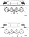
- the tug boat 1 is provided with a series of four azimuth thrusters 6, which are arranged in an aligned row that extends in transverse direction of the centre plane CP.
- the azimuth thrusters 6 have respective propellers 6a which are located below the hull 2, in this case at the stern 4. In an alternative embodiment the azimuth thrusters 6 may be located at the bow 3 or elsewhere in between.
- azimuth thruster for propelling a vessel
- ASD azimuth-stern-drive
- the entire propulsion unit can turn in the horizontal plane and thrust can be produced in any desired direction.
- two azimuth thrusters 6 are located next to each other in transverse direction of the centre plane CP and the azimuth thrusters 6 are drivably coupled to respective prime movers in the form of high-speed diesel engines 7 via respective propeller shafts 8.
- the high-speed diesel engines 7 are located within the hull 2 below a deck 9. The high-speed diesel engines 7 provide a fast response when increased thrust is desired.
- Fig. 3 shows that the propellers 6a of the outer two azimuth thrusters 6 have larger diameters than the propellers 6a of the inner two azimuth thrusters 6.
- the pair of azimuth thrusters 6 and their prime movers 7 at one side of the centre plane CP can be operated simultaneously by a first joystick and the pair of azimuth thrusters 6 and their prime movers 7 at the other side of the centre plane CP can be operated simultaneously by a second joystick.
- Fig. 4 shows an alternative embodiment, which distinguishes from the embodiment as shown in Fig. 3 in that two skegs 5a, 5b are mounted to a lower side of the hull 2.
- the skegs 5 extend in longitudinal direction of the hull 2 from the bow 3 to about halfway the hull 2 at a distance from the centre plane CP.
- each of the skegs 5a, 5b is located at a horizontal position between axes of rotation of the propellers 6a of the neighbouring azimuth thrusters 6. Due to the application of two skegs 5a, 5b their dimensions in vertical direction are relatively small, which creates a relatively small draught.
- the combination of at least two relatively small azimuth thrusters 6 and at least one skeg 5a, 5b at each side of the centre plane CP allows a small draught and facilitates docking, for example.
- the height of each of the skegs 5a, 5b may vary along its longitudinal direction. The maximum height may be smaller than the diameter or 1.5 times the diameter of each of the propellers 6a.
Landscapes
- Chemical & Material Sciences (AREA)
- Engineering & Computer Science (AREA)
- Combustion & Propulsion (AREA)
- Mechanical Engineering (AREA)
- Ocean & Marine Engineering (AREA)
- Toys (AREA)
- Structures Of Non-Positive Displacement Pumps (AREA)
- Earth Drilling (AREA)
- Glass Compositions (AREA)
- Closures For Containers (AREA)
Claims (11)
- Remorqueur (1) comprenant une coque (2) comportant une proue (3) et une poupe (4) et ayant un rapport longueur/faisceau qui est inférieur à 5:1, dans lequel la coque (2) a un plan central (CP) vertical s'étendant dans une direction allant de la proue (3) à la poupe (4), dans lequel le remorqueur (1) a au moins deux propulseurs azimutaux (6) comportant des propulseurs (6a) respectifs, lesquels propulseurs azimutaux (6) sont situés l'un à côté de l'autre dans une direction transversale du plan central (CP) et dans lequel chaque propulseur azimutal (6) est couplé par entraînement à son propre moteur d'entraînement (7),dans lequel les au moins deux propulseurs azimutaux (6) se trouvent de chaque côté du plan central (CP), ce qui représente au moins quatre propulseurs azimutaux au total,dans lequel au moins l'un des moteurs d'entraînement est un moteur diesel (7) qui a une vitesse maximale supérieure à 1 000 tr/min.
- Remorqueur (1) selon la revendication 1, dans lequel les propulseurs azimutaux (6) sont alignés dans la direction transversale du plan central (CP).
- Remorqueur (1) selon la revendication 1 ou 2, dans lequel des distances entre des lignes centrales des propulseurs (6a) de chaque paire de propulseurs azimutaux (6) voisins sont identiques.
- Remorqueur (1) selon l'une quelconque des revendications précédentes, dans lequel les propulseurs (6a) des au moins deux propulseurs azimutaux (6) ont des diamètres différents.
- Remorqueur (1) selon la revendication 4, dans lequel le propulseur (6a) de l'un des au moins deux propulseurs azimutaux (6) qui est situé à une distance plus grande par rapport au plan central (CP) que l'autre des au moins deux propulseurs azimutaux (6) a un diamètre plus important que celui du propulseur (6a) de l'autre des au moins deux propulseurs azimutaux (6).
- Remorqueur (1) selon l'une quelconque des revendications précédentes, dans lequel les propulseurs azimutaux (6) sont situés à la proue (3) ou à la poupe (4).
- Remorqueur (1) selon l'une quelconque des revendications précédentes, dans lequel les au moins deux propulseurs azimutaux (6) et leurs moteurs d'entraînement (7) sont couplés fonctionnellement à un dispositif de commande commun pour faire fonctionner les au moins deux propulseurs azimutaux (6) simultanément.
- Remorqueur (1) selon la revendication 7, dans lequel le dispositif de commande commun est un levier de commande de sorte qu'un opérateur puisse utiliser deux leviers de commande, un pour commander simultanément les au moins deux propulseurs azimutaux, y compris leurs moteurs d'entraînement, sur un côté du plan central et un pour commander simultanément les au moins deux propulseurs azimutaux, y compris leurs moteurs d'entraînement, sur l'autre côté du plan central.
- Remorqueur (1) selon l'une quelconque des revendications précédentes, dans lequel sur chaque côté du plan central (CP), une plaque de protection (5a, 5b) est montée sur un côté inférieur de la coque (2), laquelle plaque de protection (5a, 5b) s'étend dans une direction longitudinale de la coque (2).
- Remorqueur (1) selon la revendication 9, dans lequel la plaque de protection (5a, 5b) est située à une position horizontale entre des axes de rotation des propulseurs (6a) respectifs des au moins deux propulseurs azimutaux (6) telle que vue dans une direction allant de la poupe (4) à la proue (3).
- Remorqueur (1) selon la revendication 9 ou 10, dans lequel la hauteur maximale de la plaque de protection (5a, 5b) est inférieure au diamètre ou représente 1,5 fois le diamètre de chacun des propulseurs (6a) des propulseurs azimutaux (6) respectifs.
Priority Applications (7)
| Application Number | Priority Date | Filing Date | Title |
|---|---|---|---|
| ES20159261T ES2991674T3 (es) | 2020-02-25 | 2020-02-25 | Una embarcación |
| EP20159261.5A EP3871970B1 (fr) | 2020-02-25 | 2020-02-25 | Récipient |
| PCT/EP2021/054099 WO2021170493A1 (fr) | 2020-02-25 | 2021-02-19 | Vaisseau |
| US17/904,733 US20230070348A1 (en) | 2020-02-25 | 2021-02-19 | A vessel |
| AU2021226803A AU2021226803B2 (en) | 2020-02-25 | 2021-02-19 | A vessel |
| CN202180015832.9A CN115135575A (zh) | 2020-02-25 | 2021-02-19 | 船 |
| CA3168219A CA3168219A1 (fr) | 2020-02-25 | 2021-02-19 | Vaisseau |
Applications Claiming Priority (1)
| Application Number | Priority Date | Filing Date | Title |
|---|---|---|---|
| EP20159261.5A EP3871970B1 (fr) | 2020-02-25 | 2020-02-25 | Récipient |
Publications (3)
| Publication Number | Publication Date |
|---|---|
| EP3871970A1 EP3871970A1 (fr) | 2021-09-01 |
| EP3871970C0 EP3871970C0 (fr) | 2024-10-09 |
| EP3871970B1 true EP3871970B1 (fr) | 2024-10-09 |
Family
ID=69845812
Family Applications (1)
| Application Number | Title | Priority Date | Filing Date |
|---|---|---|---|
| EP20159261.5A Active EP3871970B1 (fr) | 2020-02-25 | 2020-02-25 | Récipient |
Country Status (7)
| Country | Link |
|---|---|
| US (1) | US20230070348A1 (fr) |
| EP (1) | EP3871970B1 (fr) |
| CN (1) | CN115135575A (fr) |
| AU (1) | AU2021226803B2 (fr) |
| CA (1) | CA3168219A1 (fr) |
| ES (1) | ES2991674T3 (fr) |
| WO (1) | WO2021170493A1 (fr) |
Families Citing this family (1)
| Publication number | Priority date | Publication date | Assignee | Title |
|---|---|---|---|---|
| CN114212220A (zh) * | 2021-12-07 | 2022-03-22 | 广州大学 | 一种水下检测装置及其控制方法 |
Family Cites Families (12)
| Publication number | Priority date | Publication date | Assignee | Title |
|---|---|---|---|---|
| FR585270A (fr) * | 1923-07-06 | 1925-02-24 | Appareil de propulsion pour navires | |
| US3750607A (en) * | 1971-06-23 | 1973-08-07 | D Seymour | Shallow-draft boat |
| US3934531A (en) * | 1974-07-18 | 1976-01-27 | Allen Rudolph A | Ocean going cargo transport system |
| SE8301196L (sv) * | 1983-03-04 | 1984-09-05 | Goetaverken Arendal Ab | Anordning vid farkoster med parallella skrov |
| JP5648826B2 (ja) * | 2010-02-22 | 2015-01-07 | 独立行政法人海上技術安全研究所 | 二軸船尾双胴型船舶 |
| JP2011235740A (ja) * | 2010-05-10 | 2011-11-24 | Kayseven Co Ltd | 船舶 |
| CN103482037A (zh) * | 2013-09-23 | 2014-01-01 | 浙江海洋学院 | 一种小型拖船 |
| RU2549739C1 (ru) * | 2013-11-06 | 2015-04-27 | Федеральное государственное унитарное предприятие "Крыловский государственный научный центр" | Ледокольное судно для работы преимущественно в мелководных замерзающих акваториях |
| KR20160128337A (ko) * | 2014-02-13 | 2016-11-07 | 롤스-로이스 마린 에이에스 | 주 및 이차 추진 디바이스들에 의해 제공되는 선박 추진과 관련된 개선 사항들 |
| US10132366B1 (en) * | 2014-06-06 | 2018-11-20 | Logan Clutch Corporation | Clutch assembly and system |
| WO2016023080A1 (fr) * | 2014-08-12 | 2016-02-18 | Frozen Motion Pte Ltd | Embarcation destinée à la réalisation d'opérations en surface |
| CN109334886A (zh) * | 2018-09-26 | 2019-02-15 | 蚌埠市神舟机械有限公司 | 一种高性能全回转港作拖轮 |
-
2020
- 2020-02-25 ES ES20159261T patent/ES2991674T3/es active Active
- 2020-02-25 EP EP20159261.5A patent/EP3871970B1/fr active Active
-
2021
- 2021-02-19 AU AU2021226803A patent/AU2021226803B2/en active Active
- 2021-02-19 CA CA3168219A patent/CA3168219A1/fr active Pending
- 2021-02-19 WO PCT/EP2021/054099 patent/WO2021170493A1/fr not_active Ceased
- 2021-02-19 CN CN202180015832.9A patent/CN115135575A/zh active Pending
- 2021-02-19 US US17/904,733 patent/US20230070348A1/en active Pending
Also Published As
| Publication number | Publication date |
|---|---|
| AU2021226803A1 (en) | 2022-09-15 |
| CN115135575A (zh) | 2022-09-30 |
| EP3871970C0 (fr) | 2024-10-09 |
| WO2021170493A1 (fr) | 2021-09-02 |
| CA3168219A1 (fr) | 2021-09-02 |
| ES2991674T3 (es) | 2024-12-04 |
| US20230070348A1 (en) | 2023-03-09 |
| AU2021226803B2 (en) | 2026-04-09 |
| EP3871970A1 (fr) | 2021-09-01 |
Similar Documents
| Publication | Publication Date | Title |
|---|---|---|
| US3934531A (en) | Ocean going cargo transport system | |
| EP3523194B1 (fr) | Remorqueur équipé d'unités de propulsion azimutales | |
| CN103381877A (zh) | 改进的拖船船体及包括该改进船体的拖船 | |
| US8844459B2 (en) | Tug-barge offshore cargo transport | |
| CN201505385U (zh) | 一种中舵桨港作消防船 | |
| US20020134290A1 (en) | Landing craft with fixed and retractable azimuthing drives | |
| EP2371701A1 (fr) | Navire de type remorqueur avec commande de tracteur d'azimut | |
| EP2704946B1 (fr) | Bateau de remorquage | |
| KR100249423B1 (ko) | 선박 도킹선 | |
| EP3871970B1 (fr) | Récipient | |
| US7434523B2 (en) | Speedboat hull design | |
| CN101214847A (zh) | 中小型船舶水垫抗沉系统 | |
| EP2193989A1 (fr) | Navire ayant des oeuvres fortes de section hexagonale pour deplacer une barge | |
| NL1012591C2 (nl) | Sleepboot. | |
| RU217176U1 (ru) | Корпус судна-буксира | |
| RU222507U1 (ru) | Корпус судна-буксира | |
| EP2250078A2 (fr) | Embarcation marine | |
| RU2142894C1 (ru) | Устройство для активного управления судном | |
| EP4613625A1 (fr) | Navire | |
| CN119773908B (zh) | 一种三开体船型 | |
| WO2006049483A1 (fr) | Remorqueur a appareillages de traction capable d'effectuer une rotation de 360 degres | |
| US12208867B2 (en) | Maritime apparatus | |
| RU2321520C1 (ru) | Мореходное ледокольно-транспортное судно и движительно-рулевое устройство для него | |
| WO2025151133A2 (fr) | Navire-centrale doté d'un pont à frottement faisant l'interface avec un navire submersible | |
| House | Ship Handling: Equipment |
Legal Events
| Date | Code | Title | Description |
|---|---|---|---|
| PUAI | Public reference made under article 153(3) epc to a published international application that has entered the european phase |
Free format text: ORIGINAL CODE: 0009012 |
|
| STAA | Information on the status of an ep patent application or granted ep patent |
Free format text: STATUS: THE APPLICATION HAS BEEN PUBLISHED |
|
| AK | Designated contracting states |
Kind code of ref document: A1 Designated state(s): AL AT BE BG CH CY CZ DE DK EE ES FI FR GB GR HR HU IE IS IT LI LT LU LV MC MK MT NL NO PL PT RO RS SE SI SK SM TR |
|
| STAA | Information on the status of an ep patent application or granted ep patent |
Free format text: STATUS: REQUEST FOR EXAMINATION WAS MADE |
|
| 17P | Request for examination filed |
Effective date: 20220211 |
|
| RBV | Designated contracting states (corrected) |
Designated state(s): AL AT BE BG CH CY CZ DE DK EE ES FI FR GB GR HR HU IE IS IT LI LT LU LV MC MK MT NL NO PL PT RO RS SE SI SK SM TR |
|
| P01 | Opt-out of the competence of the unified patent court (upc) registered |
Effective date: 20230517 |
|
| STAA | Information on the status of an ep patent application or granted ep patent |
Free format text: STATUS: EXAMINATION IS IN PROGRESS |
|
| 17Q | First examination report despatched |
Effective date: 20230828 |
|
| GRAP | Despatch of communication of intention to grant a patent |
Free format text: ORIGINAL CODE: EPIDOSNIGR1 |
|
| STAA | Information on the status of an ep patent application or granted ep patent |
Free format text: STATUS: GRANT OF PATENT IS INTENDED |
|
| INTG | Intention to grant announced |
Effective date: 20240506 |
|
| GRAS | Grant fee paid |
Free format text: ORIGINAL CODE: EPIDOSNIGR3 |
|
| GRAA | (expected) grant |
Free format text: ORIGINAL CODE: 0009210 |
|
| STAA | Information on the status of an ep patent application or granted ep patent |
Free format text: STATUS: THE PATENT HAS BEEN GRANTED |
|
| AK | Designated contracting states |
Kind code of ref document: B1 Designated state(s): AL AT BE BG CH CY CZ DE DK EE ES FI FR GB GR HR HU IE IS IT LI LT LU LV MC MK MT NL NO PL PT RO RS SE SI SK SM TR |
|
| REG | Reference to a national code |
Ref country code: CH Ref legal event code: EP |
|
| REG | Reference to a national code |
Ref country code: DE Ref legal event code: R096 Ref document number: 602020038892 Country of ref document: DE |
|
| REG | Reference to a national code |
Ref country code: IE Ref legal event code: FG4D |
|
| REG | Reference to a national code |
Ref country code: ES Ref legal event code: FG2A Ref document number: 2991674 Country of ref document: ES Kind code of ref document: T3 Effective date: 20241204 |
|
| U01 | Request for unitary effect filed |
Effective date: 20241025 |
|
| P04 | Withdrawal of opt-out of the competence of the unified patent court (upc) registered |
Free format text: CASE NUMBER: APP_62748/2024 Effective date: 20241125 |
|
| U07 | Unitary effect registered |
Designated state(s): AT BE BG DE DK EE FI FR IT LT LU LV MT NL PT RO SE SI Effective date: 20241128 |
|
| U20 | Renewal fee for the european patent with unitary effect paid |
Year of fee payment: 6 Effective date: 20250227 |
|
| PG25 | Lapsed in a contracting state [announced via postgrant information from national office to epo] |
Ref country code: IS Free format text: LAPSE BECAUSE OF FAILURE TO SUBMIT A TRANSLATION OF THE DESCRIPTION OR TO PAY THE FEE WITHIN THE PRESCRIBED TIME-LIMIT Effective date: 20250209 Ref country code: HR Free format text: LAPSE BECAUSE OF FAILURE TO SUBMIT A TRANSLATION OF THE DESCRIPTION OR TO PAY THE FEE WITHIN THE PRESCRIBED TIME-LIMIT Effective date: 20241009 |
|
| PG25 | Lapsed in a contracting state [announced via postgrant information from national office to epo] |
Ref country code: GR Free format text: LAPSE BECAUSE OF FAILURE TO SUBMIT A TRANSLATION OF THE DESCRIPTION OR TO PAY THE FEE WITHIN THE PRESCRIBED TIME-LIMIT Effective date: 20250110 |
|
| PG25 | Lapsed in a contracting state [announced via postgrant information from national office to epo] |
Ref country code: PL Free format text: LAPSE BECAUSE OF FAILURE TO SUBMIT A TRANSLATION OF THE DESCRIPTION OR TO PAY THE FEE WITHIN THE PRESCRIBED TIME-LIMIT Effective date: 20241009 |
|
| PG25 | Lapsed in a contracting state [announced via postgrant information from national office to epo] |
Ref country code: RS Free format text: LAPSE BECAUSE OF FAILURE TO SUBMIT A TRANSLATION OF THE DESCRIPTION OR TO PAY THE FEE WITHIN THE PRESCRIBED TIME-LIMIT Effective date: 20250109 |
|
| PG25 | Lapsed in a contracting state [announced via postgrant information from national office to epo] |
Ref country code: SM Free format text: LAPSE BECAUSE OF FAILURE TO SUBMIT A TRANSLATION OF THE DESCRIPTION OR TO PAY THE FEE WITHIN THE PRESCRIBED TIME-LIMIT Effective date: 20241009 |
|
| PG25 | Lapsed in a contracting state [announced via postgrant information from national office to epo] |
Ref country code: SK Free format text: LAPSE BECAUSE OF FAILURE TO SUBMIT A TRANSLATION OF THE DESCRIPTION OR TO PAY THE FEE WITHIN THE PRESCRIBED TIME-LIMIT Effective date: 20241009 |
|
| PG25 | Lapsed in a contracting state [announced via postgrant information from national office to epo] |
Ref country code: CZ Free format text: LAPSE BECAUSE OF FAILURE TO SUBMIT A TRANSLATION OF THE DESCRIPTION OR TO PAY THE FEE WITHIN THE PRESCRIBED TIME-LIMIT Effective date: 20241009 |
|
| PLBE | No opposition filed within time limit |
Free format text: ORIGINAL CODE: 0009261 |
|
| STAA | Information on the status of an ep patent application or granted ep patent |
Free format text: STATUS: NO OPPOSITION FILED WITHIN TIME LIMIT |
|
| PG25 | Lapsed in a contracting state [announced via postgrant information from national office to epo] |
Ref country code: MC Free format text: LAPSE BECAUSE OF FAILURE TO SUBMIT A TRANSLATION OF THE DESCRIPTION OR TO PAY THE FEE WITHIN THE PRESCRIBED TIME-LIMIT Effective date: 20241009 |
|
| 26N | No opposition filed |
Effective date: 20250710 |
|
| REG | Reference to a national code |
Ref country code: CH Ref legal event code: PL |
|
| PG25 | Lapsed in a contracting state [announced via postgrant information from national office to epo] |
Ref country code: CH Free format text: LAPSE BECAUSE OF NON-PAYMENT OF DUE FEES Effective date: 20250228 |
|
| PG25 | Lapsed in a contracting state [announced via postgrant information from national office to epo] |
Ref country code: IE Free format text: LAPSE BECAUSE OF NON-PAYMENT OF DUE FEES Effective date: 20250225 |
|
| U20 | Renewal fee for the european patent with unitary effect paid |
Year of fee payment: 7 Effective date: 20260227 |
|
| PGFP | Annual fee paid to national office [announced via postgrant information from national office to epo] |
Ref country code: GB Payment date: 20260227 Year of fee payment: 7 |
|
| PGFP | Annual fee paid to national office [announced via postgrant information from national office to epo] |
Ref country code: ES Payment date: 20260302 Year of fee payment: 7 |
|
| PGFP | Annual fee paid to national office [announced via postgrant information from national office to epo] |
Ref country code: NO Payment date: 20260227 Year of fee payment: 7 |
|
| PGFP | Annual fee paid to national office [announced via postgrant information from national office to epo] |
Ref country code: TR Payment date: 20260206 Year of fee payment: 7 |