EP3872010A1 - Verkapselter förderer - Google Patents
Verkapselter förderer Download PDFInfo
- Publication number
- EP3872010A1 EP3872010A1 EP19877376.4A EP19877376A EP3872010A1 EP 3872010 A1 EP3872010 A1 EP 3872010A1 EP 19877376 A EP19877376 A EP 19877376A EP 3872010 A1 EP3872010 A1 EP 3872010A1
- Authority
- EP
- European Patent Office
- Prior art keywords
- conveyor
- bottom plate
- enclosed
- enclosed conveyor
- enclosure
- Prior art date
- Legal status (The legal status is an assumption and is not a legal conclusion. Google has not performed a legal analysis and makes no representation as to the accuracy of the status listed.)
- Withdrawn
Links
- 239000013590 bulk material Substances 0.000 abstract description 26
- 238000009826 distribution Methods 0.000 abstract description 4
- 239000000463 material Substances 0.000 abstract description 3
- 238000009825 accumulation Methods 0.000 description 3
- 230000003247 decreasing effect Effects 0.000 description 3
- 238000005265 energy consumption Methods 0.000 description 3
- 239000011248 coating agent Substances 0.000 description 2
- 238000000576 coating method Methods 0.000 description 2
- 238000010348 incorporation Methods 0.000 description 2
- 238000004519 manufacturing process Methods 0.000 description 2
- 238000000034 method Methods 0.000 description 2
- 230000002787 reinforcement Effects 0.000 description 2
- 229910001335 Galvanized steel Inorganic materials 0.000 description 1
- 239000004698 Polyethylene Substances 0.000 description 1
- 229910000831 Steel Inorganic materials 0.000 description 1
- 230000002411 adverse Effects 0.000 description 1
- 230000008878 coupling Effects 0.000 description 1
- 238000010168 coupling process Methods 0.000 description 1
- 238000005859 coupling reaction Methods 0.000 description 1
- 239000008397 galvanized steel Substances 0.000 description 1
- 230000003647 oxidation Effects 0.000 description 1
- 238000007254 oxidation reaction Methods 0.000 description 1
- 238000010422 painting Methods 0.000 description 1
- 230000037361 pathway Effects 0.000 description 1
- 239000008188 pellet Substances 0.000 description 1
- -1 polyethylene Polymers 0.000 description 1
- 229920000573 polyethylene Polymers 0.000 description 1
- 230000002028 premature Effects 0.000 description 1
- 238000003825 pressing Methods 0.000 description 1
- 238000007789 sealing Methods 0.000 description 1
- 229910000679 solder Inorganic materials 0.000 description 1
- 238000005476 soldering Methods 0.000 description 1
- 239000010959 steel Substances 0.000 description 1
- 230000007704 transition Effects 0.000 description 1
Images




Classifications
-
- B—PERFORMING OPERATIONS; TRANSPORTING
- B65—CONVEYING; PACKING; STORING; HANDLING THIN OR FILAMENTARY MATERIAL
- B65G—TRANSPORT OR STORAGE DEVICES, e.g. CONVEYORS FOR LOADING OR TIPPING, SHOP CONVEYOR SYSTEMS OR PNEUMATIC TUBE CONVEYORS
- B65G15/00—Conveyors having endless load-conveying surfaces, i.e. belts and like continuous members, to which tractive effort is transmitted by means other than endless driving elements of similar configuration
- B65G15/08—Conveyors having endless load-conveying surfaces, i.e. belts and like continuous members, to which tractive effort is transmitted by means other than endless driving elements of similar configuration the load-carrying surface being formed by a concave or tubular belt, e.g. a belt forming a trough
-
- B—PERFORMING OPERATIONS; TRANSPORTING
- B65—CONVEYING; PACKING; STORING; HANDLING THIN OR FILAMENTARY MATERIAL
- B65G—TRANSPORT OR STORAGE DEVICES, e.g. CONVEYORS FOR LOADING OR TIPPING, SHOP CONVEYOR SYSTEMS OR PNEUMATIC TUBE CONVEYORS
- B65G15/00—Conveyors having endless load-conveying surfaces, i.e. belts and like continuous members, to which tractive effort is transmitted by means other than endless driving elements of similar configuration
- B65G15/60—Arrangements for supporting or guiding belts, e.g. by fluid jets
-
- B—PERFORMING OPERATIONS; TRANSPORTING
- B65—CONVEYING; PACKING; STORING; HANDLING THIN OR FILAMENTARY MATERIAL
- B65G—TRANSPORT OR STORAGE DEVICES, e.g. CONVEYORS FOR LOADING OR TIPPING, SHOP CONVEYOR SYSTEMS OR PNEUMATIC TUBE CONVEYORS
- B65G21/00—Supporting or protective framework or housings for endless load-carriers or traction elements of belt or chain conveyors
- B65G21/08—Protective roofs or arch supports therefor
-
- F—MECHANICAL ENGINEERING; LIGHTING; HEATING; WEAPONS; BLASTING
- F16—ENGINEERING ELEMENTS AND UNITS; GENERAL MEASURES FOR PRODUCING AND MAINTAINING EFFECTIVE FUNCTIONING OF MACHINES OR INSTALLATIONS; THERMAL INSULATION IN GENERAL
- F16C—SHAFTS; FLEXIBLE SHAFTS; ELEMENTS OR CRANKSHAFT MECHANISMS; ROTARY BODIES OTHER THAN GEARING ELEMENTS; BEARINGS
- F16C29/00—Bearings for parts moving only linearly
- F16C29/02—Sliding-contact bearings
- F16C29/025—Hydrostatic or aerostatic
-
- B—PERFORMING OPERATIONS; TRANSPORTING
- B65—CONVEYING; PACKING; STORING; HANDLING THIN OR FILAMENTARY MATERIAL
- B65G—TRANSPORT OR STORAGE DEVICES, e.g. CONVEYORS FOR LOADING OR TIPPING, SHOP CONVEYOR SYSTEMS OR PNEUMATIC TUBE CONVEYORS
- B65G2207/00—Indexing codes relating to constructional details, configuration and additional features of a handling device, e.g. Conveyors
- B65G2207/48—Wear protection or indication features
Definitions
- the present invention refers to an enclosed conveyor for bulk material comprising an enclosure having on its interior a roller capable of supporting a transport portion of a conveyor belt and an air support system capable of supporting a return portion of said conveyor belt.
- a transport portion of the enclosed conveyor, portion where the bulk material is kept and transported until the final destination, is supported by a plurality of set of rollers, or by plurality of spool-like rollers, and the return portion of the conveyor belt, portion that does not have bulk material to be transported, is supported by the bottom plate of the enclosure, with said return portion disposed over an inner surface of the bottom plate.
- said bottom plate comprises a low-friction polymeric material coating, as, for example, ultra-high-molecular-weight (UHMW) polyethylene, disposed over the inner surface facing the interior of the enclosure.
- UHMW ultra-high-molecular-weight
- JPH10218327 In order to solve the inconveniences of the conventional enclosed conveyor, there are already alternate enclosed conveyors present in the state of the art, as, for example, the conveyor of the patentary document JPH10218327 , where the conveyor belt is supported by an air film, in order to dramatically decrease the friction between said conveyor belt and the components that support both the transport portion and the return portion of said conveyor belt.
- JPH10218327 also comprises, only in the module destined to feed the bulk material to be transported, a set of rollers mounted on the side walls of the enclosure of the alternate enclosed conveyor, which is responsible for dampening the fall of such bulk material during the feeding and, consequently, for avoiding damages to the air film generation system.
- the conveyor belt is supported by an air film coming from holes cooperating with air ducts located below the conveyor belt, both in the transport portion and the return portion.
- the alternate enclosed conveyor of the state of the art that uses an air film to support the conveyor belt in the transport portion and the return portion has inconveniences when the bulk material distribution is unequal along the length of said conveyor belt.
- the bulk material is being accumulated in higher quantity in some points of the conveyor belt, generating higher pressure in such points.
- the transport portion of the conveyor belt makes contact with the surface where said transport portion moves on, increasing the friction coefficient between the conveyor belt and the bottom surface of the conveyor, causing the potency of the traction engine to increase.
- the contact of the conveyor belt on the surface where the transport portion moves on might cause a premature wear of said conveyor belt on the points where there is a higher accumulation of bulk material.
- the present invention proposes an enclosed conveyor that comprises an enclosure formed by a plurality of side walls disposed on a bottom plate and having a cover disposed over said side walls, with said bottom plate having an inner surface facing the interior of the enclosure and an outer surface facing the exterior of the enclosure.
- the proposed enclosed conveyor comprises at least a horizontal roller disposed on the interior of the enclosure and mounted on the side walls of said enclosure and a conveyor belt that comprises a transport portion disposed over said roller and a return portion disposed over the bottom plate.
- the enclosed conveyor of the present invention is characterized by comprising at least one air duct disposed on the outer surface of the bottom plate, with said bottom plate having a plurality of holes longitudinally disposed along the bottom plate, in order to enable an airflow between the interior of said air duct and the interior of the enclosure.
- the proposed enclosed conveyor comprises a plurality of air ducts, with each air duct having a linkage opening and a linkage duct cooperating with the linkage openings of consecutive air ducts.
- the proposed enclosed conveyor comprises a distinctive configuration if compared with the conventional enclosed conveyor and with the alternate enclosed conveyor, with the transport portion of the conveyor belt supported by at least a horizontal roller and the return portion of said conveyor belt supported by an air film, where said air film is formed between the inner surface of the bottom plate and the return portion.
- the return portion of the conveyor belt of the proposed enclosed conveyor is supported by an air film.
- the friction between the inner surface of the bottom plate and the return portion of the conveyor belt is dramatically decreased compared to the configuration used by the conventional enclosed conveyor. Therefore, it is possible to use a traction engine with lower potency, as there is no more potency requirement demanded by the friction force existing in the return portion of the conveyor belt of the conventional enclosed conveyor. Furthermore, the possibility for the conveyor belt to slip due to the lower potency to start the traction engine of the proposed enclosed conveyor compared to the engine of the conventional enclosed conveyor is reduced. By using a traction engine with lower potency, the energy consumption of the proposed enclosed conveyor, as well as the diameter of the traction pulleys and the pre-tension load needed to turn the conveyor belt on, are also decreased.
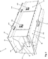
- An enclosed conveyor (10) for bulk material (100) as proposed by the present invention is comprised by a plurality of interconnectable modules in its extremities by screwed unions, in order to enable a length adjustment for said enclosed conveyor (10) by the quantity of modules according to the desired application.
- the modules of the enclosed conveyor (10) might have different lengths, but present the same components and, therefore, the quantity of modules represented in each incorporation of the present description will be better described according to each embodiment presented.
- the enclosed conveyor (10) of the present invention comprises an enclosure (20) formed by a plurality of side walls (21,22) disposed on the bottom plate (23) and have a cover (24) disposed over said side walls (21, 22), with said bottom plate (23) having an inner surface (231) facing the interior of the enclosure (20) and an outer surface (232) facing the exterior of the enclosure (20).
- the enclosed conveyor (10) comprises two side walls (21, 22).
- a first side wall (21) is mounted at one of the sides of the bottom plate (23), while a second side wall (22) is disposed at the opposite side of said bottom plate (23).
- the side walls (21, 22) are mounted at the lower plate (23) by a screwed union.
- the cover (24) a component already belonging to the state of the art, is also screwed on the side walls (21, 22).
- the bottom plate (23) and the cover (24) are comprised by metallic plates in both documents of the state of the art and of the embodiment presented in the present invention.
- the bulk material (100) is transported inside the enclosure (20) of the enclosed conveyor (10) and the inner surface (231) of the bottom plate (23) faces the interior of said enclosure (20), while the outer surface (232) of such bottom plate (23) faces the exterior of the enclosure (20).
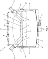
- the proposed enclosed conveyor also comprises at least a horizontal roller (43) disposed in the interior of the enclosure (20) and mounted on the side walls (21, 22) of said enclosure (20) and a conveyor belt (30) that comprises a transport portion (31) disposed over the horizontal roller (43) and a return portion (32) disposed over the bottom plate (23), as it can be seen in Figure 5 .
- the described quantity of the horizontal roller (43) refers to a transversal section of the enclosed conveyor (10) and that the quantity of horizontal rollers (43) to be used along the longitudinal extension of said enclosed conveyor (10) must be defined according to the convenience and need, in order enable the transport portion (31) of the conveyor belt (30) to be duly supported by said horizontal rollers (43) during the transportation of the bulk material (100).
- the transport portion (31) of the conveyor belt (30) is the portion disposed over the horizontal rollers (43) of the enclosed conveyor (10), where the bulk material (100) is deposited while it is being transported.
- the return portion (32) of the conveyor belt (30) returns from one of the extremities modules already described in the state of the art and then becomes disposed over the bottom plate (23) along the entire longitudinal extension of the enclosed conveyor (10), until arriving at the opposite extremity module, also already described in the state of the art, when it is then directed again over the horizontal rollers (43).
- the return portion (32) of the conveyor belt (30) is supported over the inner surface (231) of the bottom plate (23) when the enclosed conveyor (10) is not working.
- the transport portion (31) of the conveyor belt (30) is disposed over a set of rollers (40) mounted inside the enclosure (20), with said set of rollers (40) being comprised by the horizontal roller (43) and a plurality of inclined rollers (41, 42) mounted on the side walls (21, 22).
- each represented module of the enclosed conveyor (10) has two sets of rollers (40), with each set of rollers (40) comprising two inclined rollers (41, 42) and one horizontal roller (43).
- a first inclined roller (41) is mounted on the first side wall (21), a second inclined roller (42) is mounted on the second side wall (22), and the horizontal roller (43) has an extremity mounted on the first wall side (21) and another extremity mounted on the second side wall (22).
- the inclined rollers (41, 42) are comprised by a cylindrical body (411, 421) having a shaft (412, 422) coupled at one extremity, while the horizontal roller (43) is comprised by a cylindrical body (433) having shafts (431, 432) coupled at each extremity.
- the shaft (412) of the first inclined roller (41) passes through the first side wall (21) and cooperates with a first outer bearing (413) mounted on said first side wall (21) and outside the enclosure (20) of the enclosed conveyor (10).
- the shaft (422) of the second inclined roller (42) passes through the second side wall (22) and cooperates with a second outer bearing (423) mounted on said second side wall (22) and outside the enclosure (20) of the enclosed conveyor (10).
- one of the shafts (431) of the horizontal roller (43) passes through the first side wall (21) and cooperates with a third outer bearing (434) mounted on said first side wall (21) and outside the enclosure (20) of the enclosed conveyor (10), while the other shaft (432) of the horizontal roller (43) passes through the second side wall (22) and cooperates with a fourth outer bearing (435) mounted on said second side wall (22) and outside the enclosure (20) of the enclosed conveyor (10).
- the bearings (413, 423, 434, 435) of the rollers of the proposed enclosed conveyor (10) are mounted outside the enclosure (20) of said enclosed conveyor (10), however, in a non-represented embodiment, said bearings (413, 423, 434, 435) might be mounted inside said enclosure (20).
- the enclosed conveyor (10) comprises spool-like rollers, already previously described in the state of the art document, replacing the set of rollers (40) to support the transport portion (31) of the conveyor belt (30).
- the enclosed conveyor (10) of the present invention is characterized by comprising at least one air duct (50) disposed on the outer surface (232) of the bottom plate (23) of said enclosed conveyor (10), with said bottom plate (23) having a plurality of holes (233) longitudinally disposed along said bottom plate (23) in order to enable an airflow between the interior of said air duct (50) and the interior of the enclosure (20), as it can be better seen in Figure 6 .
- the holes (233) are longitudinally disposed along the enclosed conveyor (10) at a central region of the bottom plate (23).
- the air duct (50) is also disposed at a central region of the outer surface (232) of the bottom plate (23), in order to cause the holes (233) of said bottom plate (23) to be disposed into the width delimitations of said air duct (50).
- the air duct (50) is comprised by a metallic plate with a U-shaped transversal section and is disposed on the outer surface (232) of the bottom plate (23) by a screwed union, with said air duct (50) being closed in both extremities.
- the air duct (50) can be soldered on the outer surface (232) of the bottom plate (23). Notice that the air duct (50) needs to be mounted on the same region where the holes (233) of the bottom plate (23) are disposed.
- the air duct (50) is composed by a closed rectangular section.
- both the bottom plate (23) and the air duct (50) surface that makes contact with the outer surface (232) of said bottom plate (23) need to present cooperating holes between themselves in order to enable the airflow passage indisde said air duct (50) to the interior of the enclosure (20).
- the air duct (50) comprises an air opening (51), where an airflow-generating source, such as, for example, a fan, can be coupled to, in order to generate an airflow along the entire extension of said air duct (5) capable to be directed to the interior of the enclosure (20) of the enclosed conveyor (10) through the holes (233) of the bottom plate (23).
- an airflow-generating source such as, for example, a fan
- the air opening (51) of the air duct (50) is comprised by a component separated from said air duct (50); however, said air opening (51) can be comprised by at least one opening disposed on any region of said air duct (50).
- the quantity of air openings (51) and airflow-generating sources needs to be sized according to the desired function parameters for the enclosed conveyor (10).
- a person skilled in the art must be able to calculate the needed airflow demand for the correct function of the enclosed conveyor (10), in order to cause the return portion (32) of the conveyor belt (30) to be duly supported.
- a fan actuated by a 2hp engine might be used for each air opening (51) in an interval of every 30 meters.
- the return portion (32) of the conveyor belt (30) of the proposed enclosed conveyor (10) is supported by an air film.
- the fritcion between the inner surface (231) of the bottom plate (23) and the return portion (32) of the conveyor belt (30) is dramatically decreased compared to the configuration used by the conventional enclosed conveyor.
- the configuration used in the proposed enclosed conveyor (10) is possible to manufacture said enclosed conveyor (10) at a longer length compared to the conventional enclosed conveyor, as the length restriction was caused by the need for using a large traction engine with large energy consumption, traction pulleys with large diameter, and very high pre-tension loads to overcome the friction force along the entire contact area between the return portion of the conveyor belt and the UHMW-coated inner surface of the bottom plate of said conventional enclosed conveyor.
- the enclosed conveyor (10) comprises a plurality of air ducts (50), with each air duct (50) having at least one linkage opening (52) and one linkage duct (60) cooperating with the linkage openings (52) of consecutive air ducts (50). Therefore, more than one air duct (50) might be used along the longitudinal extension of the enclosed conveyor (10), with said air ducts (50) being interconnected by the linkage ducts (60).
- the linkage ducts (60) might be screwed at the linkage openings (52) of the air ducts (50)
- each module of the enclosed conveyor (10) comprises one air duct (50) mounted at the outer surface (232) of the respective bottom plate (23).
- the holes (233) on the bottom plate (23) of each module of the enclosed conveyor (10) cooperate with the respective air duct (50) mounted on said module, in order to enable the airflow coming from the interconnected air ducts (5) to be directed to the interior of the enclosure (10).
- the air ducts (50) are individually mounted for each module of the enclosed conveyor (10).
- the linkage ducts (60) cooperate to interconnect the air ducts (50) of consecutive modules.
- the linkage duct (60) is mounted at the linkage opening (52) of the air duct (50) of a module of the enclosed conveyor (10) and at the linkage opening (52) of the air duct (50) of the immediate neighboring module.
- the mounting of consecutive modules is facilitated, as each module can be already previously pre-mounted with the respective air duct (50), with only the mounting of the linkage ducts (60) remaining to interconnect said air ducts (50).
- the module coupling and the sealing of possible air escapes from the system comprised by the air ducts (50) and by the linkage ducts (60) are facilitated.
- the air ducts (50) comprise a linkage opening (52) in each extremity in order to facilitate the mounting of the linkage ducts (60). Furthermore, one pair of linkage ducts (60) is used to perform the interconnection among the consecutive air ducts (50) in order to facilitate the airflow transition among said air ducts (50). Notice that the air ducts (50) disposed in the intermediate modules of the extremities of the enclosed conveyor (10) might only have one linkage opening (52) at one extremity or one linkage opening (52) in each extremity, with the linkage opening (52) that is not connected to a linkage duct (60) being closed by a screwed cover (53).
- one of the linkage openings (52) of the air ducts (50) might be used as an air opening (51), as, for example, the linkage openings (52) with the covers (53).
- both the air ducts (50) and the linkage ducts (60) are manufactured with a galvanized steel plate.
- the air ducts (50) might be mounted at the outer surface (232) of the bottom plates (23) and the linkage ducts (60) might be mounted at the linkage openings (52) of said air ducts (50) by a screwed union, without needing to solder the cited components.
- the process of mounting the enclosed conveyor (10) is facilitated, as there is no need for painting the air ducts (50) and the linkage ducts (52), either to protect said ducts (50, 60) against bad weather or against the oxidation from the soldering process.
- the enclosed conveyor (10) might comprise a plurality of inner beams (71, 72, 73), mounted on the side walls (21, 22) and inside the enclosure (20) of the enclosed conveyor (10), and a plurality of lateral reinforcements (25) mounted on the side walls (21, 22) and outside said enclosure (20), in order to ensure a structural stability of said enclosed conveyor (10). Therefore, it is ensured that the enclosure (20) will not undergo deformations or buckling by the application of loads inherent to transporting the bulk material (100). Both the inner beams (71, 72, 73) and the lateral reinforcements (25) might be screwed or soldered at the side walls (21, 22).
Landscapes
- Engineering & Computer Science (AREA)
- Mechanical Engineering (AREA)
- General Engineering & Computer Science (AREA)
- Structure Of Belt Conveyors (AREA)
Applications Claiming Priority (2)
| Application Number | Priority Date | Filing Date | Title |
|---|---|---|---|
| BR102018071790-1A BR102018071790A2 (pt) | 2018-10-23 | 2018-10-23 | transportador enclausurado |
| PCT/BR2019/000032 WO2020082142A1 (pt) | 2018-10-23 | 2019-10-22 | Transportador enclausurado |
Publications (2)
| Publication Number | Publication Date |
|---|---|
| EP3872010A1 true EP3872010A1 (de) | 2021-09-01 |
| EP3872010A4 EP3872010A4 (de) | 2022-07-27 |
Family
ID=70330251
Family Applications (1)
| Application Number | Title | Priority Date | Filing Date |
|---|---|---|---|
| EP19877376.4A Withdrawn EP3872010A4 (de) | 2018-10-23 | 2019-10-22 | Verkapselter förderer |
Country Status (4)
| Country | Link |
|---|---|
| US (1) | US20210380345A1 (de) |
| EP (1) | EP3872010A4 (de) |
| BR (1) | BR102018071790A2 (de) |
| WO (1) | WO2020082142A1 (de) |
Families Citing this family (2)
| Publication number | Priority date | Publication date | Assignee | Title |
|---|---|---|---|---|
| US11758834B2 (en) | 2019-07-29 | 2023-09-19 | KSi Conveyor, Inc. | Method for mixing a stream of particulate material by inducing backflow within an inclined belt conveyor |
| BR102020015783A2 (pt) * | 2020-08-03 | 2022-02-15 | Tmsa - Tecnologia Em Movimentação S.A. | Transportador enclausurado |
Family Cites Families (11)
| Publication number | Priority date | Publication date | Assignee | Title |
|---|---|---|---|---|
| US2249588A (en) * | 1940-03-07 | 1941-07-15 | George A Waddle | Conveyer |
| US3809211A (en) * | 1971-12-14 | 1974-05-07 | B Padilla | Conveyor system |
| DE2509469C3 (de) * | 1975-03-05 | 1980-06-04 | The Motch & Merryweather Machinery Co., Hayward, Calif. (V.St.A.) | Pneumatische Förderanlage |
| US4451182A (en) * | 1978-10-02 | 1984-05-29 | Precision Metal Fabricators, Inc. | Air transport system |
| JPH10218327A (ja) | 1997-02-07 | 1998-08-18 | Ishikawajima Harima Heavy Ind Co Ltd | 空気浮上式ローラレスベルトコンベヤ |
| JP3333713B2 (ja) * | 1997-06-18 | 2002-10-15 | 住友重機械工業株式会社 | 空気浮上式コンベヤの清掃装置 |
| US6044965C1 (en) | 1998-02-18 | 2013-03-05 | Philip G Clark | Troughing idlers for belt conveyors |
| JP4580075B2 (ja) * | 2000-08-15 | 2010-11-10 | Ihi運搬機械株式会社 | 空気浮上式ベルトコンベヤの伸縮部構造 |
| JP3571001B2 (ja) * | 2001-03-15 | 2004-09-29 | 川崎重工業株式会社 | 空気浮上式ベルトコンベヤのトラフ接続構造 |
| US8225926B1 (en) * | 2011-02-18 | 2012-07-24 | Enduro Systems, Inc. | Troughing side idler for belt conveyors |
| US11180320B2 (en) * | 2018-03-15 | 2021-11-23 | TMSA—Tecnologia em Movimentaçâo S.A. | Enclosed conveyor |
-
2018
- 2018-10-23 BR BR102018071790-1A patent/BR102018071790A2/pt not_active Application Discontinuation
-
2019
- 2019-10-22 WO PCT/BR2019/000032 patent/WO2020082142A1/pt not_active Ceased
- 2019-10-22 EP EP19877376.4A patent/EP3872010A4/de not_active Withdrawn
- 2019-10-22 US US17/288,107 patent/US20210380345A1/en not_active Abandoned
Also Published As
| Publication number | Publication date |
|---|---|
| WO2020082142A1 (pt) | 2020-04-30 |
| EP3872010A4 (de) | 2022-07-27 |
| US20210380345A1 (en) | 2021-12-09 |
| BR102018071790A2 (pt) | 2020-05-05 |
Similar Documents
| Publication | Publication Date | Title |
|---|---|---|
| EP3872010A1 (de) | Verkapselter förderer | |
| US11180320B2 (en) | Enclosed conveyor | |
| US7571803B2 (en) | Bearing unit for a conveying installation for the transport of goods by way of a conveyor belt | |
| EP4190726A1 (de) | Geschlossener förderer | |
| US6102195A (en) | Belt conveyor | |
| US20090026046A1 (en) | Conveying Installation for the Transport of Goods | |
| US20110226591A1 (en) | Vertical pipe conveyor | |
| US6491156B1 (en) | Fluid plenum conveyor trough and method for fabricating and joining the same | |
| JP7323776B2 (ja) | ベルトコンベア乗継装置 | |
| RU2405728C1 (ru) | Винтовой конвейер | |
| JP7432147B2 (ja) | ベルトコンベアの搬送方法 | |
| US20100230251A1 (en) | Barrier Seal | |
| JP3059624B2 (ja) | コンベア用ダイバータ | |
| SU963912A1 (ru) | Лента дл наклонного конвейера | |
| JP4675495B2 (ja) | 空気浮上式ベルトコンベア装置 | |
| JPH09169418A (ja) | 上下分離型空気浮上式ベルトコンベア | |
| JP3836737B2 (ja) | 空気浮上式ベルトコンベヤ | |
| JP3461810B2 (ja) | ベルトコンベア | |
| CN210048060U (zh) | 联动式自动调偏托辊支架 | |
| JP2001048330A (ja) | 空気浮上式ベルトコンベア装置 | |
| CN118683908B (zh) | 一种抗静电耐腐蚀型输送带 | |
| CN205675746U (zh) | 用于翻车机的卸料给料装置及翻车机 | |
| CN221026142U (zh) | 防滚落在线称重装置 | |
| US771641A (en) | Straw-stacker. | |
| KR102519857B1 (ko) | 벨트 컨베이어용 스커팅 장치 및 이를 포함하는 벨트 컨베이어 |
Legal Events
| Date | Code | Title | Description |
|---|---|---|---|
| STAA | Information on the status of an ep patent application or granted ep patent |
Free format text: STATUS: THE INTERNATIONAL PUBLICATION HAS BEEN MADE |
|
| PUAI | Public reference made under article 153(3) epc to a published international application that has entered the european phase |
Free format text: ORIGINAL CODE: 0009012 |
|
| STAA | Information on the status of an ep patent application or granted ep patent |
Free format text: STATUS: REQUEST FOR EXAMINATION WAS MADE |
|
| 17P | Request for examination filed |
Effective date: 20210525 |
|
| AK | Designated contracting states |
Kind code of ref document: A1 Designated state(s): AL AT BE BG CH CY CZ DE DK EE ES FI FR GB GR HR HU IE IS IT LI LT LU LV MC MK MT NL NO PL PT RO RS SE SI SK SM TR |
|
| DAV | Request for validation of the european patent (deleted) | ||
| DAX | Request for extension of the european patent (deleted) | ||
| A4 | Supplementary search report drawn up and despatched |
Effective date: 20220628 |
|
| RIC1 | Information provided on ipc code assigned before grant |
Ipc: B65G 21/08 20060101ALI20220622BHEP Ipc: B65G 15/60 20060101ALI20220622BHEP Ipc: B65G 51/03 20060101ALI20220622BHEP Ipc: B65G 19/14 20060101ALI20220622BHEP Ipc: B65G 15/08 20060101ALI20220622BHEP Ipc: B65G 15/06 20060101AFI20220622BHEP |
|
| STAA | Information on the status of an ep patent application or granted ep patent |
Free format text: STATUS: THE APPLICATION IS DEEMED TO BE WITHDRAWN |
|
| 18D | Application deemed to be withdrawn |
Effective date: 20230126 |