EP3872507B1 - Système de gestion de batterie, procédé de gestion de batterie, bloc-batterie et véhicule électrique - Google Patents
Système de gestion de batterie, procédé de gestion de batterie, bloc-batterie et véhicule électrique Download PDFInfo
- Publication number
- EP3872507B1 EP3872507B1 EP20758685.0A EP20758685A EP3872507B1 EP 3872507 B1 EP3872507 B1 EP 3872507B1 EP 20758685 A EP20758685 A EP 20758685A EP 3872507 B1 EP3872507 B1 EP 3872507B1
- Authority
- EP
- European Patent Office
- Prior art keywords
- ocv
- battery
- soc
- value
- estimate
- Prior art date
- Legal status (The legal status is an assumption and is not a legal conclusion. Google has not performed a legal analysis and makes no representation as to the accuracy of the status listed.)
- Active
Links
Images


Classifications
-
- G—PHYSICS
- G01—MEASURING; TESTING
- G01R—MEASURING ELECTRIC VARIABLES; MEASURING MAGNETIC VARIABLES
- G01R31/00—Arrangements for testing electric properties; Arrangements for locating electric faults; Arrangements for electrical testing characterised by what is being tested not provided for elsewhere
- G01R31/36—Arrangements for testing, measuring or monitoring the electrical condition of accumulators or electric batteries, e.g. capacity or state of charge [SoC]
- G01R31/382—Arrangements for monitoring battery or accumulator variables, e.g. SoC
-
- G—PHYSICS
- G01—MEASURING; TESTING
- G01R—MEASURING ELECTRIC VARIABLES; MEASURING MAGNETIC VARIABLES
- G01R31/00—Arrangements for testing electric properties; Arrangements for locating electric faults; Arrangements for electrical testing characterised by what is being tested not provided for elsewhere
- G01R31/36—Arrangements for testing, measuring or monitoring the electrical condition of accumulators or electric batteries, e.g. capacity or state of charge [SoC]
- G01R31/382—Arrangements for monitoring battery or accumulator variables, e.g. SoC
- G01R31/3835—Arrangements for monitoring battery or accumulator variables, e.g. SoC involving only voltage measurements
-
- G—PHYSICS
- G01—MEASURING; TESTING
- G01R—MEASURING ELECTRIC VARIABLES; MEASURING MAGNETIC VARIABLES
- G01R31/00—Arrangements for testing electric properties; Arrangements for locating electric faults; Arrangements for electrical testing characterised by what is being tested not provided for elsewhere
- G01R31/36—Arrangements for testing, measuring or monitoring the electrical condition of accumulators or electric batteries, e.g. capacity or state of charge [SoC]
- G01R31/367—Software therefor, e.g. for battery testing using modelling or look-up tables
-
- G—PHYSICS
- G01—MEASURING; TESTING
- G01K—MEASURING TEMPERATURE; MEASURING QUANTITY OF HEAT; THERMALLY-SENSITIVE ELEMENTS NOT OTHERWISE PROVIDED FOR
- G01K7/00—Measuring temperature based on the use of electric or magnetic elements directly sensitive to heat ; Power supply therefor, e.g. using thermoelectric elements
- G01K7/16—Measuring temperature based on the use of electric or magnetic elements directly sensitive to heat ; Power supply therefor, e.g. using thermoelectric elements using resistive elements
- G01K7/22—Measuring temperature based on the use of electric or magnetic elements directly sensitive to heat ; Power supply therefor, e.g. using thermoelectric elements using resistive elements the element being a non-linear resistance, e.g. thermistor
-
- G—PHYSICS
- G01—MEASURING; TESTING
- G01R—MEASURING ELECTRIC VARIABLES; MEASURING MAGNETIC VARIABLES
- G01R31/00—Arrangements for testing electric properties; Arrangements for locating electric faults; Arrangements for electrical testing characterised by what is being tested not provided for elsewhere
- G01R31/36—Arrangements for testing, measuring or monitoring the electrical condition of accumulators or electric batteries, e.g. capacity or state of charge [SoC]
-
- G—PHYSICS
- G01—MEASURING; TESTING
- G01R—MEASURING ELECTRIC VARIABLES; MEASURING MAGNETIC VARIABLES
- G01R31/00—Arrangements for testing electric properties; Arrangements for locating electric faults; Arrangements for electrical testing characterised by what is being tested not provided for elsewhere
- G01R31/36—Arrangements for testing, measuring or monitoring the electrical condition of accumulators or electric batteries, e.g. capacity or state of charge [SoC]
- G01R31/3644—Constructional arrangements
- G01R31/3648—Constructional arrangements comprising digital calculation means, e.g. for performing an algorithm
-
- G—PHYSICS
- G01—MEASURING; TESTING
- G01R—MEASURING ELECTRIC VARIABLES; MEASURING MAGNETIC VARIABLES
- G01R31/00—Arrangements for testing electric properties; Arrangements for locating electric faults; Arrangements for electrical testing characterised by what is being tested not provided for elsewhere
- G01R31/36—Arrangements for testing, measuring or monitoring the electrical condition of accumulators or electric batteries, e.g. capacity or state of charge [SoC]
- G01R31/396—Acquisition or processing of data for testing or for monitoring individual cells or groups of cells within a battery
-
- H—ELECTRICITY
- H01—ELECTRIC ELEMENTS
- H01M—PROCESSES OR MEANS, e.g. BATTERIES, FOR THE DIRECT CONVERSION OF CHEMICAL ENERGY INTO ELECTRICAL ENERGY
- H01M10/00—Secondary cells; Manufacture thereof
- H01M10/42—Methods or arrangements for servicing or maintenance of secondary cells or secondary half-cells
-
- H—ELECTRICITY
- H01—ELECTRIC ELEMENTS
- H01M—PROCESSES OR MEANS, e.g. BATTERIES, FOR THE DIRECT CONVERSION OF CHEMICAL ENERGY INTO ELECTRICAL ENERGY
- H01M10/00—Secondary cells; Manufacture thereof
- H01M10/42—Methods or arrangements for servicing or maintenance of secondary cells or secondary half-cells
- H01M10/425—Structural combination with electronic components, e.g. electronic circuits integrated to the outside of the casing
-
- H—ELECTRICITY
- H01—ELECTRIC ELEMENTS
- H01M—PROCESSES OR MEANS, e.g. BATTERIES, FOR THE DIRECT CONVERSION OF CHEMICAL ENERGY INTO ELECTRICAL ENERGY
- H01M10/00—Secondary cells; Manufacture thereof
- H01M10/42—Methods or arrangements for servicing or maintenance of secondary cells or secondary half-cells
- H01M10/48—Accumulators combined with arrangements for measuring, testing or indicating the condition of cells, e.g. the level or density of the electrolyte
-
- H—ELECTRICITY
- H01—ELECTRIC ELEMENTS
- H01M—PROCESSES OR MEANS, e.g. BATTERIES, FOR THE DIRECT CONVERSION OF CHEMICAL ENERGY INTO ELECTRICAL ENERGY
- H01M10/00—Secondary cells; Manufacture thereof
- H01M10/42—Methods or arrangements for servicing or maintenance of secondary cells or secondary half-cells
- H01M10/48—Accumulators combined with arrangements for measuring, testing or indicating the condition of cells, e.g. the level or density of the electrolyte
- H01M10/482—Accumulators combined with arrangements for measuring, testing or indicating the condition of cells, e.g. the level or density of the electrolyte for several batteries or cells simultaneously or sequentially
-
- H—ELECTRICITY
- H01—ELECTRIC ELEMENTS
- H01M—PROCESSES OR MEANS, e.g. BATTERIES, FOR THE DIRECT CONVERSION OF CHEMICAL ENERGY INTO ELECTRICAL ENERGY
- H01M10/00—Secondary cells; Manufacture thereof
- H01M10/42—Methods or arrangements for servicing or maintenance of secondary cells or secondary half-cells
- H01M10/48—Accumulators combined with arrangements for measuring, testing or indicating the condition of cells, e.g. the level or density of the electrolyte
- H01M10/486—Accumulators combined with arrangements for measuring, testing or indicating the condition of cells, e.g. the level or density of the electrolyte for measuring temperature
-
- G—PHYSICS
- G01—MEASURING; TESTING
- G01R—MEASURING ELECTRIC VARIABLES; MEASURING MAGNETIC VARIABLES
- G01R31/00—Arrangements for testing electric properties; Arrangements for locating electric faults; Arrangements for electrical testing characterised by what is being tested not provided for elsewhere
- G01R31/36—Arrangements for testing, measuring or monitoring the electrical condition of accumulators or electric batteries, e.g. capacity or state of charge [SoC]
- G01R31/374—Arrangements for testing, measuring or monitoring the electrical condition of accumulators or electric batteries, e.g. capacity or state of charge [SoC] with means for correcting the measurement for temperature or ageing
-
- G—PHYSICS
- G01—MEASURING; TESTING
- G01R—MEASURING ELECTRIC VARIABLES; MEASURING MAGNETIC VARIABLES
- G01R31/00—Arrangements for testing electric properties; Arrangements for locating electric faults; Arrangements for electrical testing characterised by what is being tested not provided for elsewhere
- G01R31/36—Arrangements for testing, measuring or monitoring the electrical condition of accumulators or electric batteries, e.g. capacity or state of charge [SoC]
- G01R31/382—Arrangements for monitoring battery or accumulator variables, e.g. SoC
- G01R31/3842—Arrangements for monitoring battery or accumulator variables, e.g. SoC combining voltage and current measurements
-
- H—ELECTRICITY
- H01—ELECTRIC ELEMENTS
- H01M—PROCESSES OR MEANS, e.g. BATTERIES, FOR THE DIRECT CONVERSION OF CHEMICAL ENERGY INTO ELECTRICAL ENERGY
- H01M10/00—Secondary cells; Manufacture thereof
- H01M10/42—Methods or arrangements for servicing or maintenance of secondary cells or secondary half-cells
- H01M10/425—Structural combination with electronic components, e.g. electronic circuits integrated to the outside of the casing
- H01M2010/4271—Battery management systems including electronic circuits, e.g. control of current or voltage to keep battery in healthy state, cell balancing
-
- H—ELECTRICITY
- H01—ELECTRIC ELEMENTS
- H01M—PROCESSES OR MEANS, e.g. BATTERIES, FOR THE DIRECT CONVERSION OF CHEMICAL ENERGY INTO ELECTRICAL ENERGY
- H01M2220/00—Batteries for particular applications
- H01M2220/20—Batteries in motive systems, e.g. vehicle, ship, plane
-
- Y—GENERAL TAGGING OF NEW TECHNOLOGICAL DEVELOPMENTS; GENERAL TAGGING OF CROSS-SECTIONAL TECHNOLOGIES SPANNING OVER SEVERAL SECTIONS OF THE IPC; TECHNICAL SUBJECTS COVERED BY FORMER USPC CROSS-REFERENCE ART COLLECTIONS [XRACs] AND DIGESTS
- Y02—TECHNOLOGIES OR APPLICATIONS FOR MITIGATION OR ADAPTATION AGAINST CLIMATE CHANGE
- Y02E—REDUCTION OF GREENHOUSE GAS [GHG] EMISSIONS, RELATED TO ENERGY GENERATION, TRANSMISSION OR DISTRIBUTION
- Y02E60/00—Enabling technologies; Technologies with a potential or indirect contribution to GHG emissions mitigation
- Y02E60/10—Energy storage using batteries
Definitions
- the present disclosure relates to battery state of charge (SOC) estimation using an extended Kalman filter.
- SOC State of Charge
- the SOC is a parameter indicating a relative ratio of the remaining capacity to the maximum capacity indicating electrical energy stored in the battery when the battery is fully charged, and may be expressed as 0 to 1 or 0% to 100%. For example, when the maximum capacity and the remaining capacity of the battery are 1000Ah (ampere-hour) and 750Ah respectively, the SOC of the battery is 0.75 (or 75%).
- Ampere counting an equivalent circuit model and the extended Kalman filter are typically used to estimate the SOC of the battery.
- the ampere counting is the technique that estimates the SOC of the battery based on a cumulative current value corresponding to the current flowing through the battery accumulated over time.
- the equivalent circuit model is designed to model the connection relationship between electrical components to simulate the electrochemical properties of the battery.
- the ampere counting may have a discrepancy between the SOC estimated by ampere counting and the actual SOC. Additionally, it is very difficult to design the equivalent circuit model for sufficiently simulating the nonlinear characteristic of the battery associated with a rapid change in open circuit voltage (OCV) within a predetermined range in which the SOC is close to the full discharge state.
- OCV open circuit voltage
- the extended Kalman filter is the mathematically combined technique of the ampere counting and the equivalent circuit model to make up for the drawback of each of the ampere counting and the equivalent circuit model.
- the present disclosure is designed to solve the above-described problem, and therefore the present disclosure is directed to providing a battery management system, a battery management method, a battery pack and an electric vehicle in which in estimating (updating) the SOC of the battery in each cycle using the extended Kalman filter, open circuit voltage (OCV) information is determined based on the results of comparison between the temporary estimate indicating the SOC in the current cycle and the reference range strongly showing the nonlinear characteristic, then a definitive estimate indicating the SOC in the current cycle is determined based on the OCV information.
- OCV open circuit voltage
- the present disclosure is further directed to providing a battery management system, a battery management method and a battery pack in which the SOC of the battery is estimated with higher reliability by adjusting the maximum value of the reference range based on the maximum capacity associated with the degradation level of the battery.
- a battery management system includes a sensing unit configured to generate battery information indicating a current, a voltage and a temperature of a battery, and a control unit configured to estimate a state of charge (SOC) of the battery using an extended Kalman filter based on the battery information.
- the control unit is configured to determine a temporary estimate for a SOC in a current cycle using a time update process of the extended Kalman filter based on a previous estimate and the battery information.
- the previous estimate indicates a SOC in a previous cycle.
- the control unit is configured to determine open circuit voltage (OCV) information based on the temporary estimate.
- OCV open circuit voltage
- the control unit is configured to determine a definitive estimate indicating the SOC in the current cycle using a measurement update process of the extended Kalman filter based on the temporary estimate, the OCV information and the battery information.
- the OCV information may include a first OCV factor value.
- the control unit may be configured to determine the first OCV factor value to be equal to a predetermined first slope control value when the temporary estimate is outside of a reference range.
- the control unit may be configured to determine the first OCV factor value to be equal to a second slope control value when the temporary estimate is within the reference range.
- the second slope control value is smaller than the first slope control value.
- the control unit may be configured to determine a maximum value of the reference range based on a maximum capacity of the battery.
- the control unit may be configured to increase the maximum value of the reference range as a difference between a design capacity of the battery and the maximum capacity increases.
- the OCV information may include a second OCV factor value.
- the control unit may be configured to determine the second OCV factor value to be equal to a first OCV corresponding to the temporary estimate from a data table defining a correspondence relationship between the SOC and the OCV of the battery when the temporary estimate is outside of the reference range.
- the control unit may be configured to determine the second OCV factor value to be equal to a second OCV corresponding to a maximum value of the reference range when the temporary estimate is within the reference range.
- the maximum value of the reference range is equal to or larger than a predetermined reference value.
- a battery pack according to another aspect of the present disclosure includes the battery management system.
- An electric vehicle includes the battery pack.
- a battery management method may be executable by the battery management system.
- the battery management method includes collecting battery information indicating a current, a voltage and a temperature of the battery, determining a temporary estimate for a SOC in a current cycle using a time update process of an extended Kalman filter based on a previous estimate indicating a SOC in a previous cycle and the battery information, determining OCV information based on the temporary estimate, and determining a definitive estimate indicating the SOC in the current cycle using a measurement update process of the extended Kalman filter based on the temporary estimate, the OCV information and the battery information.
- Determining the OCV information may determining a first OCV factor value to be equal to a predetermined first slope control value when the temporary estimate is outside of a reference range, and determining the first OCV factor value to be equal to a second slope control value when the temporary estimate is within the reference range, the second slope control value being smaller than the first slope control value.
- the OCV information may include the first OCV factor value.
- Determining the OCV information may include determining a second OCV factor value to be equal to an OCV corresponding to the temporary estimate from a data table defining a correspondence relationship between the SOC and the OCV of the battery when the temporary estimate is outside of a reference range, and determining the second OCV factor value to be equal to a threshold voltage associated with the reference range when the temporary estimate is within the reference range.
- the OCV information may include the second OCV factor value.
- open circuit voltage (OCV) information in estimating (updating) the SOC of the battery in each cycle using the extended Kalman filter, open circuit voltage (OCV) information may be determined based on the results of comparison between the temporary estimate indicating the SOC in the current cycle and the reference range strongly showing the nonlinear characteristic, and a definitive estimate indicating the SOC in the current cycle may be determined based on the OCV information. Accordingly, it is possible to reduce the adverse influence of a rapid change in OCV due to the nonlinear characteristic of the battery on the accuracy of battery SOC estimation.
- control unit refers to a processing unit of at least one function or operation, and this may be implemented by either hardware or software or a combination of hardware and software.
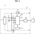
- FIG. 1 is an exemplary diagram of a configuration of an electric vehicle according to the present disclosure
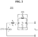
- FIG. 2 is an exemplary diagram of a circuit configuration of an equivalent circuit model of a battery
- FIG. 3 is an exemplary diagram of an open circuit voltage (OCV)-state of charge (SOC) curve of the battery.
- OCV open circuit voltage
- SOC state of charge
- a battery pack 10 is configured to supply electrical energy required for an electricity powered device such as an electric vehicle 1, and includes a battery 20, a switch 30 and a battery management system 100.
- the battery 20 includes at least one battery cell.
- Each battery cell may be, for example, a lithium ion cell.
- the type of the battery cell is not limited to the lithium ion cell, and may include, without limitation, any type that can be recharged repeatedly.
- Each battery cell included in the battery 20 is electrically connected to other battery cell in series or in parallel.
- the switch 30 is installed on a current path for charging and discharging the battery 20.
- a control terminal of the switch 30 is provided to be electrically connected to a control unit 120.
- the switch 30 is controlled to be turned on and off according to the duty cycle of a switching signal SS outputted by the control unit 120, in response to the switching signal SS being applied to the control terminal.
- the switch 30 may be turned on, and when the switching signal SS is low-level, the switch 30 may be turned off.
- the current flowing through the current path is controlled by turning on and off the switch 30.
- the battery management system 100 is provided to be electrically connected to the battery 20 to periodically determine the SOC of the battery 20.
- the battery management system 100 includes a sensing unit 110, the control unit 120, a memory unit 130 and a communication unit 140.
- the sensing unit 110 is configured to periodically generate battery information indicating the voltage, current and temperature of the battery 20 during charging/discharging of the battery 20.
- the sensing unit 110 includes a current sensor 111, a voltage sensor 112 and a temperature sensor 113.
- the current sensor 111 is provided to be electrically connected to the charge/discharge path of the battery 20.
- the current sensor 111 is configured to output a signal SI indicating the magnitude and direction of the current flowing through the battery 20 to the control unit 120.
- a shunt resistor and/or a hall effect device may be used as the current sensor 111.
- the voltage sensor 112 is provided to be electrically connected to positive and negative terminals of the battery 20.
- the voltage sensor 112 is configured to detect the voltage across the positive and negative terminals of the battery 20, and output a signal SV indicating the detected voltage to the control unit 120.
- the temperature sensor 113 is configured to detect the temperature of an area within a predetermined distance from the battery 20, and output a signal ST indicating the detected temperature to the control unit 120.
- a thermistor having the negative temperature coefficient may be used as the temperature sensor 113.
- the control unit 120 is operably coupled to the sensing unit 110, the memory unit 130, the communication unit 140 and the switch 30.
- the control unit 120 may be implemented in hardware using at least one of application specific integrated circuits (ASICs), digital signal processors (DSPs), digital signal processing devices (DSPDs), programmable logic devices (PLDs), field programmable gate arrays (FPGAs), microprocessors and electrical units for performing other functions.
- ASICs application specific integrated circuits
- DSPs digital signal processors
- DSPDs digital signal processing devices
- PLDs programmable logic devices
- FPGAs field programmable gate arrays
- microprocessors microprocessors and electrical units for performing other functions.
- the control unit 120 is configured to periodically receive the signal SI, the signal SV and the signal ST outputted by the sensing unit 110 as the battery information.
- the control unit 120 may determine a current value, a voltage value and a temperature value from the signal SI, the signal SV and the signal ST respectively using an analog-to-digital converter (ADC) included in the control unit 120, and store them in the memory unit 130.
- ADC analog-to-digital converter
- the memory unit 130 is operably coupled to the control unit 120.
- the memory unit 130 may store programs and data necessary to perform the steps described below.
- the memory unit 130 may include, for example, at least one type of storage medium of flash memory type, hard disk type, Solid State Disk (SSD) type, Silicon Disk Drive (SDD) type, multimedia card micro type, random access memory (RAM), static random access memory (SRAM), read-only memory (ROM), electrically erasable programmable read-only memory (EEPROM) and programmable read-only memory (PROM).
- the communication unit 140 may be coupled to an external device 2 to enable communication.
- the external device 2 may be an Electronic Control Unit (ECU) of the vehicle 1.
- the communication unit 140 may receive a command message from the external device 2, and provide the received command message to the control unit 120.
- the command message may be a message requesting the activation of a specific function (e.g., SOC estimation, control of ON/OFF of the switch 30) of the battery management system 100.
- the communication unit 140 may send a notification message from the control unit 120 to the external device 2.
- the notification message may be a message for notifying the result (e.g., an estimate of SOC) of the function performed by the control unit 120 to the external device 2.
- the communication unit 140 may communicate with the external device 2 via a wired network such as a local area network (LAN), a controller area network (CAN) and a daisy chain and/or a short range wireless network, for example, Bluetooth, Zigbee and WiFi.
- a wired network such as a local area network (LAN), a controller area network (CAN) and a daisy chain and/or a short range wireless network, for example, Bluetooth, Zigbee and WiFi.
- the control unit 120 is configured to determine the maximum capacity or the state of health (SOH) of the battery 20.
- the maximum capacity indicates the maximum amount of charges that can be stored in the battery 20, and may be referred to as 'full charge capacity'.
- Equation 1 Q ref denotes reference capacity
- SOC 1 denotes SOC estimated at the time point t 1
- SOC 2 denotes SOC estimated at the time point t 2
- ⁇ SOC denotes a difference between SOC 1 and SOC 2
- it denotes a current value indicating the current detected at a time point t between the time point t 1 and the time point t2
- ⁇ C denotes the cumulative current value for a period of time from the time point t 1 to the time point t2
- Q est denotes an estimate of maximum capacity at the time point t2
- SOH new denotes an estimate of SOH at the time point t2.
- Q ref is a preset value indicating the maximum capacity when the SOH of the battery 20 is 1.
- Q ref may be referred to as 'design capacity', and may be pre-stored in the memory unit 130.
- control unit 120 may be configured to determine the SOH or the maximum capacity of the battery 20 using Equation 1 only when ⁇ SOC is equal to or larger than a predetermined value (e.g., 0.5).
- control unit 120 may be configured to determine the maximum capacity of the battery 20 using Equation 1.
- the control unit 120 may calculate an estimate of SOC of the battery 20 in the current cycle using the ampere counting (see Equation 2) based on the current value of the battery information.
- SOC k + 1 SOC e k + i k + 1 ⁇ t Q est
- Equation 2 ⁇ t denotes the time length per cycle.
- K is a time index that increases by 1 each time ⁇ t passes away, and indicates the number of cycles from the time point at which a predetermined event occurred to the current time point.
- the event may be, for example, the start of charging and discharging of the battery 20 of which voltage is stabilized.
- the battery 20 of which voltage is stabilized may be the battery 20 on no-load condition in which the current does not flow through the battery 20 and the voltage of the battery 20 is uniformly maintained.
- SOC e [0] may be determined from a data table defining a correspondence relationship between OCV and SOC of the battery 20 (see the OCV-SOC curve shown in FIG. 3 ) using the OCV of the battery 20 at the time point when the event occurred as an index.
- the data table is stored in the memory unit 130.
- Equation 2 i[k+1] denotes the current detected in the current cycle, and SOC e [k] denotes the SOC determined in the previous cycle by the extended Kalman filter. SOC[k+1] is a value indicating the SOC in the current cycle calculated using the ampere counting. In Equation 2, i[k+1] may be replaced with i[k].
- the extended Kalman filter is an algorithm for periodically updating the SOC of the battery 20, by additionally using the equivalent circuit model 200 of the battery 20 together with the ampere counting represented by Equation 2.
- the equivalent circuit model 200 includes an OCV source 210, an ohm resistor R 1 and a resistor-capacitor (RC) pair 220.
- the OCV source 210 simulates the OCV that is the voltage between the positive and negative electrodes of the battery 20 electrochemically stabilized for a long term.
- the OCV outputted by the OCV source 210 may be preset by SOC and temperature through experimentation.
- the ohm resistor R 1 is associated with IR drop V 1 of the battery 20.
- the IR drop refers to an instantaneous change in voltage across the battery 20 when the battery 20 is switched from the no-load condition to the charging/discharging condition or from the charging/discharging condition to the no-load condition.
- the voltage of the battery 20 measured at the time point when the battery 20 on no-load condition starts charging is higher than the OCV.
- the voltage of the battery 20 measured at the time point when the battery 20 on no-load condition starts discharging is lower than the OCV.
- the resistance value of the ohm resistor R 1 may be also preset by SOC and temperature through experimentation.
- the RC pair 220 outputs overpotential (also known as 'polarization voltage') V 2 occurred by an electric double layer of the battery 20, etc., and includes a resistor R 2 and a capacitor C 2 connected in parallel.
- the overpotential V 2 may be referred to as 'polarization voltage'.
- the time constant of the RC pair 220 is the multiplication of the resistance value of the resistor R 2 by the capacitance of the capacitor C2, and may be preset by SOC and temperature through experimentation.
- V ecm is an output voltage of the equivalent circuit model 200, and equals the sum of the OCV from the OCV source 210, the IR drop V 1 across the ohm resistor R 1 and the overpotential V 2 across the RC pair 220.
- the overpotential in the current cycle may be defined as the following Equation 3.
- V 2 k + 1 V 2 k e ⁇ ⁇ t ⁇ k + 1 + R 2 k + 1 i k + 1 1 ⁇ e ⁇ ⁇ t ⁇ k + 1
- Equation 3 R 2 [k+1] denotes the resistance value of the resistor R 2 in the current cycle, ⁇ [k+1] denotes the time constant of the RC pair 220 in the current cycle, V2[k] denotes the overpotential in the previous cycle, and V 2 [k+1] denotes the overpotential in the current cycle.
- i[k+1] may be replaced with i[k].
- the overpotential V2[0] at the time point when the event occurred may be 0 V(volt).
- Equation 4 is a first state equation associated with the time update process of the extended Kalman filter, and is derived from a combination of Equation 2 and Equation 3.
- Equation 4 indicates a value estimated by time updates. Additionally, the superscripted symbol - indicates a value before correction by measurement updates described below.
- SOC[k+1] of Equation 4 is an estimate temporarily indicating the SOC in the current cycle, and may be referred to as 'temporary estimate'.
- SOC e [k] of Equation 4 is a definitive estimate indicating the SOC in the previous cycle, and may be referred to as 'previous estimate'.
- Equation 5 is a second state equation associated with the time update process of the extended Kalman filter.
- Equation 5 Pk denotes an error covariance matrix corrected in the previous cycle, Q k denotes a process noise covariance matrix in the previous cycle, T denotes a transpose operator, and P - k+1 denotes an error covariance matrix in the current cycle.
- P 0 [ 1 0 ; 0 1 ].
- W1 k is first process noise, and is associated with reliability of the ampere counting.
- W1 k is a predetermined positive number indicating inaccuracy of the cumulative current value calculated using the ampere counting.
- W2k is second process noise, and is associated with reliability of the equivalent circuit model 200.
- W2k is a predetermined positive number indicating inaccuracy of the parameters associated with the equivalent circuit model 200.
- the control unit 120 may determine OCV information based on the temporary estimate SOC[k+1].
- the OCV information includes at least one of a first OCV factor value and a second OCV factor value.
- the first OCV factor value and the second OCV factor value will be each described in more detail below.
- the control unit 120 When the time update process using Equation 4 and Equation 5 is completed, the control unit 120 performs a measurement update process.
- Equation 6 is a first observation equation associated with the measurement update process of the extended Kalman filter.
- K k+1 denotes a Kalman gain in the current cycle.
- R is a measurement noise covariance matrix, and has preset components.
- H k+1 is a system matrix.
- the component in the first row and the first column of H k+1 indicates change trend in OCV of the battery 20 according to the data table defining the OCV-SOC curve shown in FIG. 3 in estimating the SOC of the battery 20 in the current cycle.
- n of H k+1 is a preset positive integer (e.g., 1).
- the change trend in OCV may indicate an OCV range of interest corresponding to a SOC range of interest having the temporary estimate SOC[k+1] as the middle value.
- An OCV corresponding to the minimum value of the SOC range of interest may be equal to the minimum value of the OCV range of interest.
- An OCV corresponding to the maximum value of the SOC range of interest may be equal to the maximum value of the OCV range of interest.
- u denotes the first OCV factor value, and is a positive number for adjusting the SOC range of interest required to set the change trend in OCV. Accordingly, the OCV range of interest corresponding to the SOC range of interest is adjusted by adjusting u.
- the SOC range of interest is a difference between SOC[k+1]+0.01u and SOC[k+1]-0.01u, i.e., 0.02u.
- the OCV range of interest is a difference between f 1 (SOC[k+1]+0.01u) and f 1 (SOC[k+1]-0.01u).
- f 1 SOC[k+1]+0.01u
- f 1 SOC[k+1]-0.01u
- the control unit 120 may adjust the first OCV factor value u based on the results of comparison between the temporary estimate SOC[k+1] and the reference range.
- the reference range (see FIG. 3 ) is a SOC range in which the nonlinear characteristic is above a predetermined level, and may be set through experimentation.
- the minimum value of the reference range may be 0% indicating fully discharged state.
- the maximum value (SOC R in FIG. 3 ) of the reference range indicates the boundary between an area in which the nonlinear characteristic is exhibited and the remaining area.
- the control unit 120 may determine the maximum value SOC R of the reference range based on the maximum capacity Q est of the battery. In detail, as a difference between the design capacity Q ref and the maximum capacity Q est increases (i.e., as the battery 20 degrades), the control unit 120 may increase the maximum value SOC R of the reference range. It is because as the battery 20 degrades, the internal electrochemical state of the battery 20 becomes unstable and the area in which the nonlinear characteristic is exhibited may expand. For example, when a difference between the design capacity Q ref and the maximum capacity Q est is less than a predetermined reference difference value, the predetermined reference value (e.g., 5%) may be determined as the maximum value SOC R of the reference range.
- the predetermined reference value e.g., 5%
- the reference value may indicate the SOC at the boundary between the area in which the nonlinear characteristic of the battery 20 is exhibited and the remaining area when the battery 20 is at Beginning Of Life.
- the difference between the design capacity Q ref and the maximum capacity Q est is equal to or larger than the reference difference value
- the sum of (i) the difference between the design capacity Q ref and the maximum capacity Q est multiplied by a predetermined scaling coefficient and (ii) the reference value may be determined as the maximum value SOC R of the reference range.
- the maximum value SOC R of the reference range may be fixed to be equal to the reference value irrespective of the maximum capacity Q est .
- the control unit 120 may determine the first OCV factor value u to be equal to a predetermined first slope control value.
- the control unit 120 may determine the first OCV factor value u to be equal to a predetermined second slope control value.
- the second slope control value may be smaller than the first slope control value.
- the first slope control value may be 1 that is equal to n
- the second slope control value may be 0.5 that is smaller than n.
- the first slope control value and the second slope control value may be preset based on experimental results.
- the OCV range of interest when the first OCV factor value u is equal to the second slope control value is narrower than the OCV range of interest when the first OCV factor value u is equal to the first slope control value. Accordingly, when the temporary estimate SOC[k+1] is within the reference range, changes in OCV of the battery 20 strongly showing the nonlinear characteristic may be precisely reflected on H k+1 .
- the first OCV factor value u may be a constant (e.g., equal to n) irrespective of the temporary estimate SOC[k+1].
- Equation 7 is a second observation equation associated with the measurement update process of the extended Kalman filter.
- SOC[k+1] and V 2 [k+1] obtained from Equation 4 are each corrected by Equation 7.
- x ⁇ k + 1 SOC e k + 1
- V 2 e k + 1 x ⁇ k + 1 ⁇ + K k + 1 z k + 1 ⁇ ⁇ 1 SOC k + 1 + V 1 k + 1 + V 2 k + 1
- Equation 7 z k+1 denotes the voltage of the battery 20 measured in the current cycle, V 1 [k+1] denotes the voltage across the ohm resistor R 1 in the current cycle, and may equal the multiplication of any one of i[k+1] and i[k] by R 1 [k+1].
- R 1 [k+1] is the resistance value of the ohm resistor R 1 in the current cycle.
- the control unit 120 may determine R 1 [k+1] based on the temperature value of the battery information.
- the memory unit 130 records a first lookup table defining a correspondence relationship between the temperature value and the resistance value of the ohm resistor R 1 .
- the control unit 120 may obtain the resistance value mapped to the temperature value in the current cycle as R 1 [k+1] from the first lookup table using the temperature value in the current cycle as an index.
- f 1 (SOC[k+1]) denotes the second OCV factor value.
- the control unit 120 may determine the OCV corresponding to the temporary estimate SOC[k+1] as the second OCV factor value from the data table (see FIG. 3 ).
- f 1 (SOC[k+1]) indicates an estimate of OCV in the current cycle.
- the control unit 120 may determine the OCV (V R in FIG. 2 ) corresponding to the maximum value SOC R of the reference range as the second OCV factor value from the data table (see FIG. 3 ).
- control unit 120 sets i[k+1](or i[k]) of Equation 4 to be equal to the current value and z k+1 of Equation 7 to be equal to the voltage value of the battery information. Accordingly, the control unit 120 may obtain SOC e [k+1] by correcting the temporary estimate SOC[k+1] using Equation 7.
- SOC e [k+1] is a value determined as an estimate for SOC of the battery 20 in the current cycle, and may be referred to as 'definitive estimate'.
- V 2e [k+1] is the result of correcting V 2 [k+1] of Equation 4 by Equation 7.
- SOC e [k+1] is used for SOC e [k] of Equation 4 in the next cycle.
- Equation 8 is a third observation equation associated with the measurement update process of the extended Kalman filter.
- P k + 1 E ⁇ K k + 1 H k + 1 P k + 1 ⁇
- Equation 8 E denotes the unit matrix.
- P - k+1 obtained from Equation 5 is corrected to Pk+i by Equation 8.
- the control unit 120 updates the definitive estimate indicating the SOC of the battery 20 in each cycle by performing each calculation step of Equations 4 to 8 at least once each time the time index k increases by 1.
- the control unit 120 determines R 2 [k+1] and ⁇ [k+1] of Equation 4 based on the temperature value and the SOC determined in the previous cycle.
- the memory unit 130 may record a second lookup table defining a correspondence relationship between the SOC, the temperature value and the resistance value of the resistor R 2 .
- the control unit 120 may obtain the resistance value mapped to the temperature value and the SOC determined in the previous cycle as R 2 [k+1] of Equation 4 from the second lookup table using the temperature value and the SOC determined in the previous cycle as an index.
- the memory unit 130 may record a third lookup table defining a correspondence relationship between the SOC, the temperature value and the time constant.
- the control unit 120 may obtain the time constant mapped to the temperature value and the SOC determined in the previous cycle as ⁇ [k+1] of Equation 4 from the third lookup table using the temperature value and the SOC determined in the previous cycle as an index.
- the control unit 120 may selectively output the switching signal SS.
- the control unit 120 may regulate the duty cycle of the switching signal SS below a predetermined reference duty cycle (e.g., 0.2).
- a predetermined reference duty cycle e.g. 0.
- FIG. 4 is an exemplary flowchart showing a battery management method that may be performed by the battery management system of FIG. 1 .
- the method of FIG. 4 may be periodically performed from the time point at which the event occurred.
- the method of FIG. 4 may end when charging/discharging the battery 20 is stopped.
- step S410 the control unit 120 collects battery information indicating the current, voltage and temperature of the battery 20 from the sensing unit 110.
- step S420 the control unit 120 determines a temporary estimate SOC[k+1] for the SOC in the current cycle using the time update process of the extended Kalman filter based on the previous estimate SOC e [k] indicating the SOC in the previous cycle and the battery information (see Equations 4 and 5).
- step S430 the control unit 120 determines OCV information based on the temporary estimate SOC[k+1].
- step S440 the control unit 120 determines a definitive estimate SOC e [k+1] indicating the SOC in the current cycle using the measurement update process of the extended Kalman filter based on the temporary estimate SOC[k+1], the OCV information and the battery information (see Equations 6 to 8).
- step S450 the control unit 120 transmits a notification message indicating the definitive estimate SOC e [k+1] to the external device 2 through the communication unit 140.
- FIG. 5 is an exemplary flowchart showing a method of determining the first OCV factor value as the OCV information according to an embodiment of the present disclosure.
- the method of FIG. 5 corresponds sub-steps of the step S430 of FIG. 4 .
- step S500 the control unit 120 determines the maximum value SOC R of the reference range based on the maximum capacity Q est of the battery 20.
- the minimum value of the reference range may be 0%.
- the step S500 is not essential, and may be omitted from the method of FIG. 5 .
- step S510 the control unit 120 determines whether the temporary estimate SOC[k+1] is within the reference range. That is, the control unit 120 determines whether the temporary estimate SOC[k+1] is equal to or less than the maximum value SOC R of the reference range.
- step S520 is performed.
- step S530 is performed.
- step S520 the control unit 120 determines the first OCV factor value (u in Equation 6) to be equal to the predetermined first slope control value.
- step S530 the control unit 120 determines the first OCV factor value to be equal to the predetermined second slope control value.
- the second slope control value is smaller than the first slope control value.
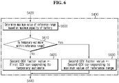
- FIG. 6 is an exemplary flowchart showing a method of determining the second OCV factor value as the OCV information according to another embodiment of the present disclosure.
- the method of FIG. 6 corresponds to sub-steps of the step S430 of FIG 4 .
- step S600 the control unit 120 determines the maximum value SOC R of the reference range based on the maximum capacity Q est of the battery 20.
- the minimum value of the reference range may be 0%.
- the step S600 is not essential, and may be omitted from the method of FIG. 6 .
- step S610 the control unit 120 determines whether the temporary estimate SOC[k+1] is within the reference range. That is, the control unit 120 determines whether the temporary estimate SOC[k+1] is equal to or less than the maximum value SOC R of the reference range.
- step S620 is performed.
- step S630 is performed.
Landscapes
- Physics & Mathematics (AREA)
- General Physics & Mathematics (AREA)
- Engineering & Computer Science (AREA)
- Manufacturing & Machinery (AREA)
- Chemical & Material Sciences (AREA)
- Chemical Kinetics & Catalysis (AREA)
- Electrochemistry (AREA)
- General Chemical & Material Sciences (AREA)
- Microelectronics & Electronic Packaging (AREA)
- Nonlinear Science (AREA)
- Secondary Cells (AREA)
Claims (12)
- Système de gestion de batterie comprenant :une unité de détection configurée pour générer des informations de batterie indiquant une intensité, une tension et une température d'une batterie ; etune unité de commande configurée pour estimer un état de charge, SOC, de la batterie en utilisant un filtre de Kalman étendu sur la base des informations de batterie,dans lequel le système de gestion de batterie est caractérisé en ce que l'unité de commande est configurée pour :déterminer une estimation provisoire d'un SOC dans un cycle courant en utilisant un processus de mise à jour temporelle du filtre de Kalman étendu sur la base d'une estimation précédente et des informations de batterie, dans lequel l'estimation précédente indique un SOC dans un cycle précédent,déterminer des informations de tension en circuit ouvert, OCV, sur la base de l'estimation provisoire, etdéterminer une estimation définitive indiquant le SOC dans le cycle courant en utilisant un processus de mise à jour de mesure du filtre de Kalman étendu sur la base de l'estimation provisoire, des informations OCV et des informations de batterie.
- Système de gestion de batterie selon la revendication 1, dans lequel les informations OCV incluent une première valeur de facteur OCV, et
l'unité de commande est configurée pour déterminer que la première valeur de facteur OCV est égale à une première valeur de commande de pente prédéterminée lorsque l'estimation provisoire est à l'extérieur d'une plage de référence. - Système de gestion de batterie selon la revendication 2, dans lequel l'unité de commande est configurée pour déterminer que la première valeur de facteur OCV est égale à une seconde valeur de commande de pente lorsque l'estimation provisoire est à l'intérieur de la plage de référence, la seconde valeur de commande de pente étant inférieure à la première valeur de commande de pente.
- Système de gestion de batterie selon la revendication 3, dans lequel l'unité de commande est configurée pour déterminer une valeur maximale de la plage de référence sur la base d'une capacité maximale de la batterie.
- Système de gestion de batterie selon la revendication 4, dans lequel l'unité de commande est configurée pour augmenter la valeur maximale de la plage de référence au fur et à mesure de l'augmentation d'une différence entre une capacité nominale de la batterie et la capacité maximale.
- Système de gestion de batterie selon la revendication 1, dans lequel les informations OCV incluent une seconde valeur de facteur OCV, et
l'unité de commande est configurée pour déterminer que la seconde valeur de facteur OCV est égale à une première OCV correspondant à l'estimation provisoire à partir d'une table de données définissant une relation de correspondance entre le SOC et l'OCV de la batterie lorsque l'estimation provisoire est à l'extérieur de la plage de référence. - Système de gestion de batterie selon la revendication 6, dans lequel l'unité de commande est configurée pour déterminer que la seconde valeur de facteur OCV est égale à une seconde OCV correspondant à une valeur maximale de la plage de référence lorsque l'estimation provisoire est à l'intérieur de la plage de référence, et dans lequel la valeur maximale de la plage de référence est supérieure ou égale à une valeur de référence prédéterminée.
- Bloc-batterie comprenant le système de gestion de batterie selon l'une quelconque des revendications 1 à 7.
- Véhicule électrique comprenant le bloc-batterie selon la revendication 8.
- Procédé de gestion de batterie exécutable par le système de gestion de batterie selon l'une quelconque des revendications 1 à 7, le procédé de gestion de batterie comprenant :la collecte d'informations de batterie indiquant une intensité, une tension et une température de la batterie ;dans lequel le procédé de gestion de batterie est caractérisé par :la détermination d'une estimation provisoire d'un état de charge, SOC, dans un cycle courant en utilisant un processus de mise à jour temporelle d'un filtre de Kalman étendu sur la base d'une estimation précédente indiquant un SOC dans un cycle précédent et des informations de batterie ;la détermination d'informations de tension en circuit ouvert, OCV, sur la base de l'estimation provisoire ; etla détermination d'une estimation définitive indiquant le SOC dans le cycle courant en utilisant un processus de mise à jour de mesure du filtre de Kalman étendu sur la base de l'estimation provisoire, des informations OCV et des informations de batterie.
- Procédé de gestion de batterie selon la revendication 10, dans lequel la détermination des informations OCV comprend :la détermination que la première valeur de facteur OCV est égale à une première valeur de commande de pente prédéterminée lorsque l'estimation provisoire est à l'extérieur d'une plage de référence ; etla détermination que la première valeur de facteur OCV est égale à une seconde valeur de commande de pente lorsque l'estimation provisoire est à l'intérieur de la plage de référence, la seconde valeur de commande de pente étant inférieure à la première valeur de commande de pente, etdans lequel les informations OCV incluent la première valeur de facteur OCV.
- Procédé de gestion de batterie selon la revendication 10, dans lequel la détermination des informations OCV comprend :la détermination qu'une seconde valeur de facteur OCV est égale à une OCV correspondant à l'estimation provisoire à partir d'une table de données définissant une relation de correspondance entre le SOC et l'OCV de la batterie lorsque l'estimation provisoire est à l'extérieur d'une plage de référence ; etla détermination que la seconde valeur de facteur OCV est égale à une tension de seuil associée à la plage de référence lorsque l'estimation provisoire est à l'intérieur de la plage de référence, etdans lequel les informations OCV incluent la seconde valeur de facteur OCV.
Applications Claiming Priority (3)
| Application Number | Priority Date | Filing Date | Title |
|---|---|---|---|
| KR20190021448 | 2019-02-22 | ||
| KR1020200013286A KR102757388B1 (ko) | 2019-02-22 | 2020-02-04 | 배터리 관리 시스템, 배터리 관리 방법, 배터리 팩 및 전기 차량 |
| PCT/KR2020/001773 WO2020171442A1 (fr) | 2019-02-22 | 2020-02-07 | Système de gestion de batterie, procédé de gestion de batterie, bloc-batterie et véhicule électrique |
Publications (3)
| Publication Number | Publication Date |
|---|---|
| EP3872507A1 EP3872507A1 (fr) | 2021-09-01 |
| EP3872507A4 EP3872507A4 (fr) | 2021-12-15 |
| EP3872507B1 true EP3872507B1 (fr) | 2022-05-11 |
Family
ID=72144351
Family Applications (1)
| Application Number | Title | Priority Date | Filing Date |
|---|---|---|---|
| EP20758685.0A Active EP3872507B1 (fr) | 2019-02-22 | 2020-02-07 | Système de gestion de batterie, procédé de gestion de batterie, bloc-batterie et véhicule électrique |
Country Status (2)
| Country | Link |
|---|---|
| EP (1) | EP3872507B1 (fr) |
| WO (1) | WO2020171442A1 (fr) |
Families Citing this family (1)
| Publication number | Priority date | Publication date | Assignee | Title |
|---|---|---|---|---|
| EP4068559A1 (fr) | 2021-03-29 | 2022-10-05 | Goodrich Lighting Systems GmbH & Co. KG | Module d'alimentation électrique d'urgence d'un avion |
Family Cites Families (6)
| Publication number | Priority date | Publication date | Assignee | Title |
|---|---|---|---|---|
| DE10056969A1 (de) * | 2000-11-17 | 2002-05-23 | Bosch Gmbh Robert | Verfahren und Anordnung zur Bestimmung des Ladezustandes einer Batterie |
| KR100793616B1 (ko) * | 2005-06-13 | 2008-01-10 | 주식회사 엘지화학 | 배터리 잔존량 추정 장치 및 방법 |
| JP4830382B2 (ja) * | 2005-07-19 | 2011-12-07 | 日産自動車株式会社 | 二次電池の充電率推定装置 |
| JP4923462B2 (ja) * | 2005-07-25 | 2012-04-25 | 日産自動車株式会社 | 二次電池の充電率推定装置 |
| JP5393619B2 (ja) * | 2010-08-26 | 2014-01-22 | カルソニックカンセイ株式会社 | バッテリの充電率推定装置 |
| US9244129B2 (en) * | 2013-01-29 | 2016-01-26 | Mitsubishi Electronic Research Laboratories, Inc. | Method for estimating a state of charge of batteries |
-
2020
- 2020-02-07 WO PCT/KR2020/001773 patent/WO2020171442A1/fr not_active Ceased
- 2020-02-07 EP EP20758685.0A patent/EP3872507B1/fr active Active
Also Published As
| Publication number | Publication date |
|---|---|
| EP3872507A4 (fr) | 2021-12-15 |
| EP3872507A1 (fr) | 2021-09-01 |
| WO2020171442A1 (fr) | 2020-08-27 |
Similar Documents
| Publication | Publication Date | Title |
|---|---|---|
| US11567137B2 (en) | Battery management system, battery management method, battery pack and electric vehicle | |
| EP3828568B1 (fr) | Appareil de gestion de batterie, procédé de gestion de batterie et batterie | |
| US12122262B2 (en) | Battery management system, battery pack, electric vehicle, and battery management method | |
| EP3828567B1 (fr) | Dispositif de gestion de batterie, procédé de gestion de batterie et bloc-batterie | |
| JP6844090B2 (ja) | バッテリーのための等価回路モデルのパラメータを推定する方法及びバッテリー管理システム | |
| CN110741267B (zh) | 估计用于电池的等效电路模型的参数的方法和电池管理系统 | |
| EP3805768B1 (fr) | Appareil de gestion de batterie, procédé de gestion de batterie et bloc-batterie | |
| EP3872507B1 (fr) | Système de gestion de batterie, procédé de gestion de batterie, bloc-batterie et véhicule électrique | |
| KR102646373B1 (ko) | 배터리 관리 시스템, 배터리 관리 방법 및 배터리 팩 |
Legal Events
| Date | Code | Title | Description |
|---|---|---|---|
| STAA | Information on the status of an ep patent application or granted ep patent |
Free format text: STATUS: THE INTERNATIONAL PUBLICATION HAS BEEN MADE |
|
| PUAI | Public reference made under article 153(3) epc to a published international application that has entered the european phase |
Free format text: ORIGINAL CODE: 0009012 |
|
| STAA | Information on the status of an ep patent application or granted ep patent |
Free format text: STATUS: REQUEST FOR EXAMINATION WAS MADE |
|
| 17P | Request for examination filed |
Effective date: 20210525 |
|
| AK | Designated contracting states |
Kind code of ref document: A1 Designated state(s): AL AT BE BG CH CY CZ DE DK EE ES FI FR GB GR HR HU IE IS IT LI LT LU LV MC MK MT NL NO PL PT RO RS SE SI SK SM TR |
|
| A4 | Supplementary search report drawn up and despatched |
Effective date: 20211112 |
|
| RIC1 | Information provided on ipc code assigned before grant |
Ipc: H01M 10/42 20060101ALI20211108BHEP Ipc: G01R 31/367 20190101ALI20211108BHEP Ipc: G01R 31/396 20190101ALI20211108BHEP Ipc: G01R 31/3835 20190101AFI20211108BHEP |
|
| GRAP | Despatch of communication of intention to grant a patent |
Free format text: ORIGINAL CODE: EPIDOSNIGR1 |
|
| STAA | Information on the status of an ep patent application or granted ep patent |
Free format text: STATUS: GRANT OF PATENT IS INTENDED |
|
| RIC1 | Information provided on ipc code assigned before grant |
Ipc: H01M 10/48 20060101ALI20220118BHEP Ipc: H01M 10/42 20060101ALI20220118BHEP Ipc: G01R 31/367 20190101ALI20220118BHEP Ipc: G01R 31/396 20190101ALI20220118BHEP Ipc: G01R 31/3835 20190101AFI20220118BHEP |
|
| DAV | Request for validation of the european patent (deleted) | ||
| DAX | Request for extension of the european patent (deleted) | ||
| INTG | Intention to grant announced |
Effective date: 20220208 |
|
| RAP3 | Party data changed (applicant data changed or rights of an application transferred) |
Owner name: LG ENERGY SOLUTION, LTD. |
|
| GRAS | Grant fee paid |
Free format text: ORIGINAL CODE: EPIDOSNIGR3 |
|
| GRAA | (expected) grant |
Free format text: ORIGINAL CODE: 0009210 |
|
| STAA | Information on the status of an ep patent application or granted ep patent |
Free format text: STATUS: THE PATENT HAS BEEN GRANTED |
|
| AK | Designated contracting states |
Kind code of ref document: B1 Designated state(s): AL AT BE BG CH CY CZ DE DK EE ES FI FR GB GR HR HU IE IS IT LI LT LU LV MC MK MT NL NO PL PT RO RS SE SI SK SM TR |
|
| REG | Reference to a national code |
Ref country code: GB Ref legal event code: FG4D |
|
| REG | Reference to a national code |
Ref country code: CH Ref legal event code: EP |
|
| REG | Reference to a national code |
Ref country code: AT Ref legal event code: REF Ref document number: 1491867 Country of ref document: AT Kind code of ref document: T Effective date: 20220515 |
|
| REG | Reference to a national code |
Ref country code: DE Ref legal event code: R096 Ref document number: 602020003183 Country of ref document: DE |
|
| REG | Reference to a national code |
Ref country code: IE Ref legal event code: FG4D |
|
| REG | Reference to a national code |
Ref country code: SE Ref legal event code: TRGR |
|
| REG | Reference to a national code |
Ref country code: LT Ref legal event code: MG9D |
|
| REG | Reference to a national code |
Ref country code: NL Ref legal event code: MP Effective date: 20220511 |
|
| REG | Reference to a national code |
Ref country code: AT Ref legal event code: MK05 Ref document number: 1491867 Country of ref document: AT Kind code of ref document: T Effective date: 20220511 |
|
| PG25 | Lapsed in a contracting state [announced via postgrant information from national office to epo] |
Ref country code: PT Free format text: LAPSE BECAUSE OF FAILURE TO SUBMIT A TRANSLATION OF THE DESCRIPTION OR TO PAY THE FEE WITHIN THE PRESCRIBED TIME-LIMIT Effective date: 20220912 Ref country code: NO Free format text: LAPSE BECAUSE OF FAILURE TO SUBMIT A TRANSLATION OF THE DESCRIPTION OR TO PAY THE FEE WITHIN THE PRESCRIBED TIME-LIMIT Effective date: 20220811 Ref country code: NL Free format text: LAPSE BECAUSE OF FAILURE TO SUBMIT A TRANSLATION OF THE DESCRIPTION OR TO PAY THE FEE WITHIN THE PRESCRIBED TIME-LIMIT Effective date: 20220511 Ref country code: LT Free format text: LAPSE BECAUSE OF FAILURE TO SUBMIT A TRANSLATION OF THE DESCRIPTION OR TO PAY THE FEE WITHIN THE PRESCRIBED TIME-LIMIT Effective date: 20220511 Ref country code: HR Free format text: LAPSE BECAUSE OF FAILURE TO SUBMIT A TRANSLATION OF THE DESCRIPTION OR TO PAY THE FEE WITHIN THE PRESCRIBED TIME-LIMIT Effective date: 20220511 Ref country code: GR Free format text: LAPSE BECAUSE OF FAILURE TO SUBMIT A TRANSLATION OF THE DESCRIPTION OR TO PAY THE FEE WITHIN THE PRESCRIBED TIME-LIMIT Effective date: 20220812 Ref country code: FI Free format text: LAPSE BECAUSE OF FAILURE TO SUBMIT A TRANSLATION OF THE DESCRIPTION OR TO PAY THE FEE WITHIN THE PRESCRIBED TIME-LIMIT Effective date: 20220511 Ref country code: BG Free format text: LAPSE BECAUSE OF FAILURE TO SUBMIT A TRANSLATION OF THE DESCRIPTION OR TO PAY THE FEE WITHIN THE PRESCRIBED TIME-LIMIT Effective date: 20220811 Ref country code: AT Free format text: LAPSE BECAUSE OF FAILURE TO SUBMIT A TRANSLATION OF THE DESCRIPTION OR TO PAY THE FEE WITHIN THE PRESCRIBED TIME-LIMIT Effective date: 20220511 |
|
| PG25 | Lapsed in a contracting state [announced via postgrant information from national office to epo] |
Ref country code: RS Free format text: LAPSE BECAUSE OF FAILURE TO SUBMIT A TRANSLATION OF THE DESCRIPTION OR TO PAY THE FEE WITHIN THE PRESCRIBED TIME-LIMIT Effective date: 20220511 Ref country code: PL Free format text: LAPSE BECAUSE OF FAILURE TO SUBMIT A TRANSLATION OF THE DESCRIPTION OR TO PAY THE FEE WITHIN THE PRESCRIBED TIME-LIMIT Effective date: 20220511 Ref country code: LV Free format text: LAPSE BECAUSE OF FAILURE TO SUBMIT A TRANSLATION OF THE DESCRIPTION OR TO PAY THE FEE WITHIN THE PRESCRIBED TIME-LIMIT Effective date: 20220511 Ref country code: IS Free format text: LAPSE BECAUSE OF FAILURE TO SUBMIT A TRANSLATION OF THE DESCRIPTION OR TO PAY THE FEE WITHIN THE PRESCRIBED TIME-LIMIT Effective date: 20220911 |
|
| PG25 | Lapsed in a contracting state [announced via postgrant information from national office to epo] |
Ref country code: SM Free format text: LAPSE BECAUSE OF FAILURE TO SUBMIT A TRANSLATION OF THE DESCRIPTION OR TO PAY THE FEE WITHIN THE PRESCRIBED TIME-LIMIT Effective date: 20220511 Ref country code: SK Free format text: LAPSE BECAUSE OF FAILURE TO SUBMIT A TRANSLATION OF THE DESCRIPTION OR TO PAY THE FEE WITHIN THE PRESCRIBED TIME-LIMIT Effective date: 20220511 Ref country code: RO Free format text: LAPSE BECAUSE OF FAILURE TO SUBMIT A TRANSLATION OF THE DESCRIPTION OR TO PAY THE FEE WITHIN THE PRESCRIBED TIME-LIMIT Effective date: 20220511 Ref country code: ES Free format text: LAPSE BECAUSE OF FAILURE TO SUBMIT A TRANSLATION OF THE DESCRIPTION OR TO PAY THE FEE WITHIN THE PRESCRIBED TIME-LIMIT Effective date: 20220511 Ref country code: EE Free format text: LAPSE BECAUSE OF FAILURE TO SUBMIT A TRANSLATION OF THE DESCRIPTION OR TO PAY THE FEE WITHIN THE PRESCRIBED TIME-LIMIT Effective date: 20220511 Ref country code: DK Free format text: LAPSE BECAUSE OF FAILURE TO SUBMIT A TRANSLATION OF THE DESCRIPTION OR TO PAY THE FEE WITHIN THE PRESCRIBED TIME-LIMIT Effective date: 20220511 Ref country code: CZ Free format text: LAPSE BECAUSE OF FAILURE TO SUBMIT A TRANSLATION OF THE DESCRIPTION OR TO PAY THE FEE WITHIN THE PRESCRIBED TIME-LIMIT Effective date: 20220511 |
|
| REG | Reference to a national code |
Ref country code: DE Ref legal event code: R097 Ref document number: 602020003183 Country of ref document: DE |
|
| PLBE | No opposition filed within time limit |
Free format text: ORIGINAL CODE: 0009261 |
|
| STAA | Information on the status of an ep patent application or granted ep patent |
Free format text: STATUS: NO OPPOSITION FILED WITHIN TIME LIMIT |
|
| PG25 | Lapsed in a contracting state [announced via postgrant information from national office to epo] |
Ref country code: AL Free format text: LAPSE BECAUSE OF FAILURE TO SUBMIT A TRANSLATION OF THE DESCRIPTION OR TO PAY THE FEE WITHIN THE PRESCRIBED TIME-LIMIT Effective date: 20220511 |
|
| 26N | No opposition filed |
Effective date: 20230214 |
|
| P01 | Opt-out of the competence of the unified patent court (upc) registered |
Effective date: 20230512 |
|
| PG25 | Lapsed in a contracting state [announced via postgrant information from national office to epo] |
Ref country code: MC Free format text: LAPSE BECAUSE OF FAILURE TO SUBMIT A TRANSLATION OF THE DESCRIPTION OR TO PAY THE FEE WITHIN THE PRESCRIBED TIME-LIMIT Effective date: 20220511 |
|
| REG | Reference to a national code |
Ref country code: CH Ref legal event code: PL |
|
| REG | Reference to a national code |
Ref country code: BE Ref legal event code: MM Effective date: 20230228 |
|
| PG25 | Lapsed in a contracting state [announced via postgrant information from national office to epo] |
Ref country code: LU Free format text: LAPSE BECAUSE OF NON-PAYMENT OF DUE FEES Effective date: 20230207 Ref country code: LI Free format text: LAPSE BECAUSE OF NON-PAYMENT OF DUE FEES Effective date: 20230228 Ref country code: CH Free format text: LAPSE BECAUSE OF NON-PAYMENT OF DUE FEES Effective date: 20230228 |
|
| REG | Reference to a national code |
Ref country code: IE Ref legal event code: MM4A |
|
| PG25 | Lapsed in a contracting state [announced via postgrant information from national office to epo] |
Ref country code: IT Free format text: LAPSE BECAUSE OF FAILURE TO SUBMIT A TRANSLATION OF THE DESCRIPTION OR TO PAY THE FEE WITHIN THE PRESCRIBED TIME-LIMIT Effective date: 20220511 Ref country code: IE Free format text: LAPSE BECAUSE OF NON-PAYMENT OF DUE FEES Effective date: 20230207 |
|
| PG25 | Lapsed in a contracting state [announced via postgrant information from national office to epo] |
Ref country code: BE Free format text: LAPSE BECAUSE OF NON-PAYMENT OF DUE FEES Effective date: 20230228 |
|
| PG25 | Lapsed in a contracting state [announced via postgrant information from national office to epo] |
Ref country code: BG Free format text: LAPSE BECAUSE OF FAILURE TO SUBMIT A TRANSLATION OF THE DESCRIPTION OR TO PAY THE FEE WITHIN THE PRESCRIBED TIME-LIMIT Effective date: 20220511 |
|
| PG25 | Lapsed in a contracting state [announced via postgrant information from national office to epo] |
Ref country code: BG Free format text: LAPSE BECAUSE OF FAILURE TO SUBMIT A TRANSLATION OF THE DESCRIPTION OR TO PAY THE FEE WITHIN THE PRESCRIBED TIME-LIMIT Effective date: 20220511 |
|
| PG25 | Lapsed in a contracting state [announced via postgrant information from national office to epo] |
Ref country code: CY Free format text: LAPSE BECAUSE OF FAILURE TO SUBMIT A TRANSLATION OF THE DESCRIPTION OR TO PAY THE FEE WITHIN THE PRESCRIBED TIME-LIMIT; INVALID AB INITIO Effective date: 20200207 |
|
| PG25 | Lapsed in a contracting state [announced via postgrant information from national office to epo] |
Ref country code: HU Free format text: LAPSE BECAUSE OF FAILURE TO SUBMIT A TRANSLATION OF THE DESCRIPTION OR TO PAY THE FEE WITHIN THE PRESCRIBED TIME-LIMIT; INVALID AB INITIO Effective date: 20200207 |
|
| PG25 | Lapsed in a contracting state [announced via postgrant information from national office to epo] |
Ref country code: TR Free format text: LAPSE BECAUSE OF FAILURE TO SUBMIT A TRANSLATION OF THE DESCRIPTION OR TO PAY THE FEE WITHIN THE PRESCRIBED TIME-LIMIT Effective date: 20220511 |
|
| PG25 | Lapsed in a contracting state [announced via postgrant information from national office to epo] |
Ref country code: SI Free format text: LAPSE BECAUSE OF FAILURE TO SUBMIT A TRANSLATION OF THE DESCRIPTION OR TO PAY THE FEE WITHIN THE PRESCRIBED TIME-LIMIT Effective date: 20220511 |
|
| PGFP | Annual fee paid to national office [announced via postgrant information from national office to epo] |
Ref country code: SE Payment date: 20260121 Year of fee payment: 7 |
|
| PGFP | Annual fee paid to national office [announced via postgrant information from national office to epo] |
Ref country code: GB Payment date: 20260122 Year of fee payment: 7 |
|
| PGFP | Annual fee paid to national office [announced via postgrant information from national office to epo] |
Ref country code: DE Payment date: 20260120 Year of fee payment: 7 |
|
| PGFP | Annual fee paid to national office [announced via postgrant information from national office to epo] |
Ref country code: FR Payment date: 20260121 Year of fee payment: 7 |