EP3872776B1 - Dispositif et procédé de distribution de produits liquides chauds et froids dans une machine de distribution - Google Patents
Dispositif et procédé de distribution de produits liquides chauds et froids dans une machine de distribution Download PDFInfo
- Publication number
- EP3872776B1 EP3872776B1 EP20382136.8A EP20382136A EP3872776B1 EP 3872776 B1 EP3872776 B1 EP 3872776B1 EP 20382136 A EP20382136 A EP 20382136A EP 3872776 B1 EP3872776 B1 EP 3872776B1
- Authority
- EP
- European Patent Office
- Prior art keywords
- dispensing
- container
- cap
- clamp
- product
- Prior art date
- Legal status (The legal status is an assumption and is not a legal conclusion. Google has not performed a legal analysis and makes no representation as to the accuracy of the status listed.)
- Active
Links
Images





Classifications
-
- G—PHYSICS
- G07—CHECKING-DEVICES
- G07F—COIN-FREED OR LIKE APPARATUS
- G07F17/00—Coin-freed apparatus for hiring articles; Coin-freed facilities or services
- G07F17/0064—Coin-freed apparatus for hiring articles; Coin-freed facilities or services for processing of food articles
- G07F17/0078—Food articles which need to be processed for dispensing in a hot or cooked condition, e.g. popcorn, nuts
-
- G—PHYSICS
- G07—CHECKING-DEVICES
- G07F—COIN-FREED OR LIKE APPARATUS
- G07F13/00—Coin-freed apparatus for controlling dispensing or fluids, semiliquids or granular material from reservoirs
- G07F13/06—Coin-freed apparatus for controlling dispensing or fluids, semiliquids or granular material from reservoirs with selective dispensing of different fluids or materials or mixtures thereof
-
- G—PHYSICS
- G07—CHECKING-DEVICES
- G07F—COIN-FREED OR LIKE APPARATUS
- G07F13/00—Coin-freed apparatus for controlling dispensing or fluids, semiliquids or granular material from reservoirs
- G07F13/10—Coin-freed apparatus for controlling dispensing or fluids, semiliquids or granular material from reservoirs with associated dispensing of containers, e.g. cups or other articles
Definitions
- the object of the invention is a device and method for dispensing hot and cold liquid products in a dispensing machine, stored in containers with a cap, the products being dispensed to the user in a vessel, such as a glass or bowl.
- vending machines that store products that must be refrigerated.
- the product is generally dispensed to the user at the temperature at which it is refrigerated, and in a container that the user has to open in order to consume it.
- a first technical problem associated with this type of vending machine is that there are certain products that are usually consumed hot, such as soups or purees, and that these machines serve at very low temperatures, resulting in a negative experience for the user.
- a second associated technical problem is that it is inconvenient for the user to have to open the product they have purchased in order to consume it, since they can stain or spill it over themselves in the process, especially in the case of liquid products.
- the state of the art discloses devices that store hot and cold products in the same machine. These devices are very large as they comprise the mechanisms necessary to keep some products cold and others hot. In addition, products that are kept warm should not be stored in the device for very long periods of time, so they must be replaced regularly if they are not consumed.
- document US5168795A describes an automatic food frying and vending system, having a refrigerated storage chamber for storing food material to be fried, and a frying chamber for frying material in cooking oil.
- the refrigerated chamber includes a stocker unit for receiving and keeping a number of packed containers, each sealed by a lid.
- a holder and a cutter are disposed on a movable table which moves in a horizontal direction, so that, when the container is transferred to the holder, the holder is positioned in the vicinity of the storage chamber, and, when the sealed lid of the container is opened, the cutter is positioned over a frying basket in the frying chamber to enable the food material to be dropped by their own weight into the frying basket simultaneously with the opening of the sealed lid.
- a guide member covers the top of a cup supported on a placement table. After filling with the cooked food, the table moves downwardly for removal of the filled cup from a takeout port.
- document US2019/0069722A1 describes an automated kitchen system, that comprises a plurality of ingredient containers, each configured to contain or store food ingredients; caps configured to close on the ingredient containers; a storage apparatus comprising compartments, each configured to store a plurality of ingredient containers, and a refrigeration mechanism, configured to cool the food ingredients in the container of the storage apparatus; transport boxes each configured to contain capped ingredient containers; a transportation apparatus configured to move the transport boxes; a cap opening apparatus configured to remove a cap from a capped container; a first transfer apparatus configured to move a capped ingredient container from a transport box to the storage apparatus, and also configured to move a capped ingredient container to a location on the cap opening apparatus.
- JPH0281198A discloses a device for dispensing hot and cold liquid products in a dispensing machine. A liquid product is heated without extracting the product from its container or opening the container and the unopened container is dispensed.
- the present invention proposes a device and method for dispensing hot and cold liquid products in a dispensing machine, which enables the previously described problems of the state of the art to be solved.
- the present invention enables products to be stored in containers provided with a cap and to be dispensed, to be heated when they are products to be served hot, to remove the cap from the container, and to serve them to the customer in a glass or bowl. This is all carried out without any contact between the product and the dispensing machine, or the selected product and other products dispensed in the machine.
- the present invention comprises a fixed structure of the dispensing machine and a dispensing area where the product is heated, the cap is removed from the container and the product is served in a bowl.
- it comprises a storage mechanism, preferably of the paternoster left type, which enables a greater number of containers to be stored compared to other devices of the state of the art.
- the storage mechanism preferably comprises at least two pairs of gears, associated with the fixed structure, and two chains, each one associated with a pair of gears, to transmit the movement. At least one storage guide is positioned between both chains, which is parallel to the ground.
- a pusher mechanism or a horizontal spiral is positioned on the storage guide, in which the containers of the dispensed products are placed, preferably secured by the cap, with the container hanging vertically from the guide. As the containers are dispensed, they are moved to one end of the storage guide either by means of the pusher or by means of the horizontal spiral.
- the device further comprises a dispensing mechanism, which collects the container of the selected product from the storage guide.
- the dispensing mechanism comprises a dispensing clamp, intended to collect the product, preferably securing it by the cap.
- the dispensing clamp moves on a first guide, which is associated with the fixed structure, from the storage mechanism to the dispensing area.
- the dispensing mechanism further comprises a heating clamp, which can move on a second guide, which is also associated with the fixed structure and perpendicular to the first guide, from a position away from the container, to the dispensing area, being intended to come into contact with the container holding the dispensing clamp.
- the dispensing mechanism comprises a heater, positioned on the face of the heating clamp that comes into contact with the product.
- This heater has the advantage that it enables the product to be dispensed to reach a high temperature in a short period of time and without the need for direct contact with the product, which is advantageous for hygiene and sanitary reasons.
- the device further comprises an uncapping mechanism, intended to remove the cap from the container once it has been heated.
- the uncapping mechanism comprises, first of all, a bent structure, associated with the fixed structure, and a mobile platform associated with said bent structure. The mobile platform can move with respect to the bent structure, from the dispensing area to a cap removal area.
- the uncapping mechanism further comprises a motor, positioned on the mobile platform, and an uncapping element, which is associated with the motor.
- the uncapping element is located over the cap of the container.
- the uncapping element rotates on itself and descends vertically, coming into contact with the cap, unscrewing and holding it once it has been removed from the container.
- the uncapping mechanism further comprises a protrusion, associated with the bent structure, and positioned in the cap removal area.
- This uncapping mechanism therefore allows the cap to be removed from the container without the need to damage the latter, preventing the liquid product from coming into contact with any element of the device.
- the device comprises a turning mechanism, associated with the first guide and with the dispensing clamp.
- the turning mechanism rotates with respect to the first guide, preferably an angle of 180°, pulling the dispensing clamp, pouring the product out of the container, which no longer has a cap.
- the device may comprise two separate container storage mechanisms, one for products to be served hot, and another for products to be served cold and can be refrigerated.
- it can be the same dispensing mechanism that collects the hot and cold products interchangeably, but in the event that the product is going to be dispensed cold, the heating clamp will not heat the container and its contents.
- the device comprises a second dispensing mechanism, a second uncapping mechanism and a second turning mechanism, responsible for dispensing, removing the cap and pouring the cold product into a glass, completely independently of the first dispensing mechanism, first uncapping mechanism and first turning mechanism, in this case responsible for products intended to be served hot.
- the invention enables liquid products to be dispensed, which may or may not be heated, directly in a bowl or glass, without the product coming into contact with any element of the device and without the user having to remove it from the container.
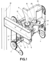
- the present invention describes a device for dispensing hot and cold liquid products in a dispensing machine, stored in containers (2) provided with a cap (1), which is shown in Figure 1 .
- the device comprises a fixed structure (18) of the dispensing machine, a storage mechanism (19), a dispensing mechanism (9), a dispensing area, where the product is heated, the cap (1) is removed from the container (2) and the product is served in a glass, an uncapping mechanism (16) and a turning mechanism (8).
- the storage mechanism (19) which can be seen in Figure 2 in a first embodiment, comprises two pairs of gears (4) associated with the fixed structure (18), and two chains (3), each one of them surrounding a pair of gears (1) and intended to transmit movement.
- the storage mechanism (19) further comprises at least one storage guide (5), attached to the two chains (3), parallel to the ground.
- a horizontal spiral is positioned on the storage guide (5) in which the containers (2) secured by the cap (1) are placed, with the container (2) hanging vertically under the storage guide (5).
- the products advance to one end of the storage guide (5) due to the horizontal spiral rotating on itself.
- a pusher is located on the storage guide (5), which performs the same function of moving the containers (2) to the end of said storage guide (5) in order to be dispensed.
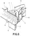
- the dispensing mechanism (9) comprises a dispensing clamp (7), which is movable by means of a first guide (6), associated with the fixed structure (18), from the storage mechanism (19) to the dispensing area, said dispensing clamp being intended to collect the container (2) from the storage mechanism (19) by the cap (1), as shown in Figure 3 .
- the dispensing mechanism (9) further comprises a heating clamp (10), which can move on a second guide (12), associated with the fixed structure (18) and perpendicular to the first guide (6), from a position away from the container (2), to the dispensing area, coming into contact with the container (2), which the dispensing clamp (7) holds by the cap (1).
- a heating clamp (10) which can move on a second guide (12), associated with the fixed structure (18) and perpendicular to the first guide (6), from a position away from the container (2), to the dispensing area, coming into contact with the container (2), which the dispensing clamp (7) holds by the cap (1).
- a heater (11) which is intended to heat the product contained in the container (2), located on the face of the heating clamp (10) that comes into contact with the container (2).
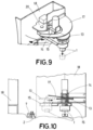
- the uncapping mechanism (16) removes the cap (1) from the container (2). Therefore, the uncapping mechanism (16) comprises a bent structure (20) associated with the fixed structure (18), a mobile platform (15), associated with the bent structure (20), and that can be moved with respect to it from the dispensing area to a cap removal area.
- the uncapping mechanism (16) further comprises a motor (14), positioned on the mobile platform (15), and an uncapping element (13), which is associated with the motor (14).
- the uncapping element (13) is located over the cap (1) of the container (2) held by the dispensing clamp (7).
- the motor (14) is started, the uncapping element (13) rotates on itself and descends vertically, coming into contact with the cap (1), unscrewing and holding it once it has been detached from the container (2).
- the mobile platform (15) moves from the dispensing area to the cap removal area.
- a protrusion (17) which is associated with the bent structure (20) that appears in Figure 9 , is positioned.
- the device comprises a turning mechanism (8), which appears in Figure 11 .
- the turning mechanism (8) is associated with the first guide (6) and with the dispensing clamp (6) and can rotate on itself. When rotating on itself, the turning mechanism (8) pulls the dispensing clamp (6) that holds the container (2) which no longer has a cap.
- the container (2) rotates on itself an angle of 180°, the liquid product being poured into, for example, a bowl or glass, to be consumed straight away by the user.
Landscapes
- Physics & Mathematics (AREA)
- General Physics & Mathematics (AREA)
- Life Sciences & Earth Sciences (AREA)
- Engineering & Computer Science (AREA)
- Food Science & Technology (AREA)
- Closures For Containers (AREA)
- Filling Of Jars Or Cans And Processes For Cleaning And Sealing Jars (AREA)
- Devices For Dispensing Beverages (AREA)
- Sealing Of Jars (AREA)
Claims (4)
- Dispositif permettant de distribuer des produits liquides chauds et froids dans une machine de distribution, stockés dans des contenants (2) munis d'un bouchon (1), qui comprend :- une structure fixe (18) de la machine de distribution,- un mécanisme de stockage (19) pour des contenants (2) associé à la structure fixe (18),- une zone de distribution où le produit est chauffé, le bouchon (1) est enlevé du contenant (2) et le produit contenu dans le contenant (2) est servi,- un mécanisme de distribution (9) comprenant :caractérisé en ce que le dispositif comprend en outre :- un premier guide (6) associé à la structure fixe,- une pince de distribution (7), qui est mobile au moyen du premier guide (6), du mécanisme de stockage (19) jusqu'à la zone de distribution, la pince de distribution (7) étant destinée à prélever le contenant (2) du mécanisme de stockage (19) au moyen du bouchon (1) et à le transporter jusqu'à la zone de distribution,- un second guide (12), associé à la structure fixe (18), perpendiculaire au premier guide (6),- une pince chauffante (10), qui est mobile au moyen du second guide (12), d'une position éloignée du contenant (2) jusqu'à la zone de distribution, destinée à venir en contact avec le contenant (2) positionné dans la pince de distribution (7),- un élément chauffant (11), situé sur une face de la pince chauffante (10), qui vient en contact avec le contenant (2), destiné à chauffer le produit stocké dans le contenant (2), et- un mécanisme de débouchage (16) associé à la structure fixe (18), destiné à enlever le bouchon (1) du contenant (2) positionné dans la pince de distribution (7) lorsque le produit a été chauffé, dans lequel le mécanisme de débouchage (16) comprend :- une structure coudée (20), associée à la structure fixe (18),- une zone d'enlèvement de bouchon, où le bouchon (1) est éjecté,- une plate-forme mobile (15), associée à la structure coudée (20), et mobile par rapport à celle-ci de la zone de distribution jusqu'à la zone d'enlèvement de bouchon,- un moteur (14), positionné sur la plate-forme mobile (15),- un élément de débouchage (13), associé au moteur (14), qui est situé au-dessus du bouchon (1) du contenant (2) lorsque la plate-forme mobile (15) est dans la zone de distribution, et qui tourne sur lui-même en descendant verticalement lorsque le moteur (14) est activé, dévissant le bouchon (1) et le maintenant lorsqu'il a été séparé du contenant (2),- une saillie (17) par rapport à la structure coudée (20), positionnée dans la zone d'enlèvement de bouchon, qui vient en contact en appuyant sur la partie supérieure de l'élément de débouchage (13), lorsque la plate-forme mobile (15) se déplace de la zone de distribution jusqu'à la zone de débouchage, le bouchon (1) étant séparé de l'élément de débouchage (13), le bouchon (1) tombant par gravité, et- un mécanisme de rotation (8), associée au premier guide (6) et à la pince de distribution (7), qui tourne par rapport au premier guide (6) en entraînant la pince de distribution (7) et le contenant (2), versant le produit contenu dans ledit contenant (2).
- Dispositif selon la revendication 1, dans lequel le mécanisme de stockage (19) comprend :- au moins deux paires d'engrenages (4), associées à la structure fixe (18),- au moins deux chaînes (3), chacune entourant une paire d'engrenages (4),- au moins un guide de stockage (5), fixé aux deux chaînes (3) et positionné horizontalement, destiné à tenir les contenants (2) assujettis par le bouchon (1) avec le contenant (2) suspendu sous le guide de stockage (5).
- Dispositif selon la revendication 1, dans lequel le mécanisme de stockage (19), le mécanisme de distribution (9), le mécanisme de débouchage (16) et le mécanisme de rotation (8) sont destinés à servir des produits chauds, et comprenant en outre un second mécanisme de stockage (19), un second mécanisme de distribution (9), un second mécanisme de débouchage (16) et un second mécanisme de rotation (8), destinés à servir des produits froids.
- Procédé permettant de distribuer des produits liquides chauds et froids, qui utilise le dispositif selon l'une quelconque des revendications 1 à 3, comprenant les étapes suivantes :- sélectionner le produit devant être distribué,- prélever le contenant (2) contenant le produit sélectionné du mécanisme de stockage (19) avec la pince de distribution (7), en le tenant par le bouchon (1),- déplacer la pince de distribution (7) à travers le premier guide (6) jusqu'à la zone de distribution,caractérisé en ce que le procédé comprend en outre les étapes consistant à :- déplacer, si le produit est servi chaud, la pince chauffante (10) à travers le second guide (12) jusqu'à ce qu'elle vienne en contact avec le contenant (2),- chauffer, si le produit est servi chaud, le produit contenu dans le contenant (2) avec l'élément chauffant (11) associé à la pince chauffante (10),- dévisser et enlever le bouchon de produit avec le mécanisme de débouchage (16),- faire tourner le mécanisme de rotation (8) qui tire la pince de distribution (7), versant le produit contenu dans le contenant (2) dans un récipient.
Priority Applications (4)
| Application Number | Priority Date | Filing Date | Title |
|---|---|---|---|
| EP20382136.8A EP3872776B1 (fr) | 2020-02-26 | 2020-02-26 | Dispositif et procédé de distribution de produits liquides chauds et froids dans une machine de distribution |
| ES20382136T ES2955797T3 (es) | 2020-02-26 | 2020-02-26 | Dispositivo y método de dispensación en máquina dispensadora de productos fluidos fríos y calientes |
| PCT/EP2021/053661 WO2021170444A1 (fr) | 2020-02-26 | 2021-02-15 | Dispositif et procédé de distribution de produits liquides chauds et froids dans une machine de distribution |
| US17/783,498 US12165459B2 (en) | 2020-02-26 | 2021-02-15 | Device and method for dispensing hot and cold liquid products in a dispensing machine |
Applications Claiming Priority (1)
| Application Number | Priority Date | Filing Date | Title |
|---|---|---|---|
| EP20382136.8A EP3872776B1 (fr) | 2020-02-26 | 2020-02-26 | Dispositif et procédé de distribution de produits liquides chauds et froids dans une machine de distribution |
Publications (3)
| Publication Number | Publication Date |
|---|---|
| EP3872776A1 EP3872776A1 (fr) | 2021-09-01 |
| EP3872776C0 EP3872776C0 (fr) | 2023-07-12 |
| EP3872776B1 true EP3872776B1 (fr) | 2023-07-12 |
Family
ID=71111380
Family Applications (1)
| Application Number | Title | Priority Date | Filing Date |
|---|---|---|---|
| EP20382136.8A Active EP3872776B1 (fr) | 2020-02-26 | 2020-02-26 | Dispositif et procédé de distribution de produits liquides chauds et froids dans une machine de distribution |
Country Status (4)
| Country | Link |
|---|---|
| US (1) | US12165459B2 (fr) |
| EP (1) | EP3872776B1 (fr) |
| ES (1) | ES2955797T3 (fr) |
| WO (1) | WO2021170444A1 (fr) |
Citations (1)
| Publication number | Priority date | Publication date | Assignee | Title |
|---|---|---|---|---|
| JPH0281198A (ja) * | 1988-09-16 | 1990-03-22 | Fuji Electric Co Ltd | 自動販売機の商品加熱方法 |
Family Cites Families (8)
| Publication number | Priority date | Publication date | Assignee | Title |
|---|---|---|---|---|
| CH664886A5 (fr) * | 1985-04-30 | 1988-04-15 | Nestle Sa | Appareil pour la confection automatique d'une boisson. |
| US5168795A (en) * | 1990-11-29 | 1992-12-08 | Higashi Hiroshima Golf Shinko Kabushiki Kaisha | Automatic food frying and vending system |
| FR2718624B1 (fr) * | 1994-04-14 | 1996-05-15 | Roger Blanc | Installation pour restauration rapide. |
| FR2733124B1 (fr) * | 1995-04-21 | 1997-08-14 | Acknin Christian | Procede de fabrication mecanisee de mets sales ou sucres a base de pate et d'ingredients contenus dans des dosettes et machine a cet effet |
| IT1308665B1 (it) * | 1999-12-03 | 2002-01-09 | Unione Di A Gubbini L | Apparecchio distributore di pizze calde. |
| US9384621B1 (en) * | 2012-07-30 | 2016-07-05 | Kil Jae Chang | Product and cup dispensing mechanisms concentrically arranged on common rotatable wheel in a sanitized vending machine |
| US11363916B2 (en) * | 2016-11-14 | 2022-06-21 | Zhengxu He | Automatic kitchen system |
| ITUA20164001A1 (it) * | 2016-05-31 | 2017-12-01 | Orbe S R L | Apparato e metodo di erogazione di una quantita' di detergente in dosi e monodosi |
-
2020
- 2020-02-26 ES ES20382136T patent/ES2955797T3/es active Active
- 2020-02-26 EP EP20382136.8A patent/EP3872776B1/fr active Active
-
2021
- 2021-02-15 US US17/783,498 patent/US12165459B2/en active Active
- 2021-02-15 WO PCT/EP2021/053661 patent/WO2021170444A1/fr not_active Ceased
Patent Citations (1)
| Publication number | Priority date | Publication date | Assignee | Title |
|---|---|---|---|---|
| JPH0281198A (ja) * | 1988-09-16 | 1990-03-22 | Fuji Electric Co Ltd | 自動販売機の商品加熱方法 |
Also Published As
| Publication number | Publication date |
|---|---|
| EP3872776C0 (fr) | 2023-07-12 |
| ES2955797T3 (es) | 2023-12-07 |
| WO2021170444A1 (fr) | 2021-09-02 |
| EP3872776A1 (fr) | 2021-09-01 |
| US12165459B2 (en) | 2024-12-10 |
| US20230005322A1 (en) | 2023-01-05 |
Similar Documents
| Publication | Publication Date | Title |
|---|---|---|
| US7051646B2 (en) | System for transferring individual coffee packages from a container to the extraction chamber of a machine for making espresso coffee | |
| US9361746B2 (en) | Automatic catering machine and method for operating it | |
| US10687655B2 (en) | Beverage brewing device for brewing and removal of different sized beverage capsules | |
| RU2620957C2 (ru) | Устройство для приготовления напитков с устранением каплеобразования | |
| US4505193A (en) | Industrial deep-fryer | |
| US5224415A (en) | Frozen food storage and dispensing system | |
| US6383542B1 (en) | method and apparatus for preparing and dispensing a combination of food products in a vending machine | |
| EP0662230A1 (fr) | Distributeur automatique d'aliments, notamment d'aliments chauds tels que pains grilles, sandwichs, pizzas et brioches | |
| WO1991012729A1 (fr) | Distributeur automatique de glaces | |
| US11523709B2 (en) | Frying unit | |
| WO2014115073A1 (fr) | Préparation automatique d'une boisson telle que du thé aux perles | |
| US3080078A (en) | Method of and apparatus for dispensing hot foods | |
| EP3872776B1 (fr) | Dispositif et procédé de distribution de produits liquides chauds et froids dans une machine de distribution | |
| US2551765A (en) | Cabinet housing several inverted containers, with a valved spout for each of said containers | |
| WO2016187539A2 (fr) | Appareil et procédé d'emballage alimentaire micro-ondable | |
| JP2005327222A (ja) | 茹でた麺を調理する保温庫内臓の麺類自動販売機 | |
| US2334654A (en) | Method of forming coated frozen confections | |
| WO2001016904A1 (fr) | Distributeurs de nourriture chaude | |
| WO2013143706A1 (fr) | Contenant pour produits alimentaires immergés dans un liquide | |
| EP1107201B1 (fr) | Machine de vente de boissons avec un arrangement amélioré pour déplacer les bec-verseurs | |
| WO2005015509A1 (fr) | Appareil de distribution automatique de produits alimentaires cuits, notamment, de pizzas chaudes | |
| US5884499A (en) | Chilled condiment dispenser | |
| NL2022514B1 (nl) | Werkwijze en inrichting voor het verpakken van vruchtvlees van een automatisch geschilde en ontkernde ananas in een houder. | |
| GB2124073A (en) | A filter lid for a fondue set and for a deep-fryer | |
| US20070108221A1 (en) | Method and Apparatus for Vending Cryogenically Frozen Dessert Particles |
Legal Events
| Date | Code | Title | Description |
|---|---|---|---|
| PUAI | Public reference made under article 153(3) epc to a published international application that has entered the european phase |
Free format text: ORIGINAL CODE: 0009012 |
|
| STAA | Information on the status of an ep patent application or granted ep patent |
Free format text: STATUS: REQUEST FOR EXAMINATION WAS MADE |
|
| 17P | Request for examination filed |
Effective date: 20210209 |
|
| AK | Designated contracting states |
Kind code of ref document: A1 Designated state(s): AL AT BE BG CH CY CZ DE DK EE ES FI FR GB GR HR HU IE IS IT LI LT LU LV MC MK MT NL NO PL PT RO RS SE SI SK SM TR |
|
| STAA | Information on the status of an ep patent application or granted ep patent |
Free format text: STATUS: EXAMINATION IS IN PROGRESS |
|
| 17Q | First examination report despatched |
Effective date: 20211220 |
|
| GRAP | Despatch of communication of intention to grant a patent |
Free format text: ORIGINAL CODE: EPIDOSNIGR1 |
|
| STAA | Information on the status of an ep patent application or granted ep patent |
Free format text: STATUS: GRANT OF PATENT IS INTENDED |
|
| INTG | Intention to grant announced |
Effective date: 20230419 |
|
| GRAS | Grant fee paid |
Free format text: ORIGINAL CODE: EPIDOSNIGR3 |
|
| GRAA | (expected) grant |
Free format text: ORIGINAL CODE: 0009210 |
|
| STAA | Information on the status of an ep patent application or granted ep patent |
Free format text: STATUS: THE PATENT HAS BEEN GRANTED |
|
| AK | Designated contracting states |
Kind code of ref document: B1 Designated state(s): AL AT BE BG CH CY CZ DE DK EE ES FI FR GB GR HR HU IE IS IT LI LT LU LV MC MK MT NL NO PL PT RO RS SE SI SK SM TR |
|
| REG | Reference to a national code |
Ref country code: CH Ref legal event code: EP |
|
| REG | Reference to a national code |
Ref country code: DE Ref legal event code: R096 Ref document number: 602020013645 Country of ref document: DE |
|
| REG | Reference to a national code |
Ref country code: IE Ref legal event code: FG4D |
|
| U01 | Request for unitary effect filed |
Effective date: 20230810 |
|
| U07 | Unitary effect registered |
Designated state(s): AT BE BG DE DK EE FI FR IT LT LU LV MT NL PT SE SI Effective date: 20230818 |
|
| REG | Reference to a national code |
Ref country code: LT Ref legal event code: MG9D |
|
| REG | Reference to a national code |
Ref country code: ES Ref legal event code: FG2A Ref document number: 2955797 Country of ref document: ES Kind code of ref document: T3 Effective date: 20231207 |
|
| PG25 | Lapsed in a contracting state [announced via postgrant information from national office to epo] |
Ref country code: GR Free format text: LAPSE BECAUSE OF FAILURE TO SUBMIT A TRANSLATION OF THE DESCRIPTION OR TO PAY THE FEE WITHIN THE PRESCRIBED TIME-LIMIT Effective date: 20231013 |
|
| PG25 | Lapsed in a contracting state [announced via postgrant information from national office to epo] |
Ref country code: IS Free format text: LAPSE BECAUSE OF FAILURE TO SUBMIT A TRANSLATION OF THE DESCRIPTION OR TO PAY THE FEE WITHIN THE PRESCRIBED TIME-LIMIT Effective date: 20231112 |
|
| PG25 | Lapsed in a contracting state [announced via postgrant information from national office to epo] |
Ref country code: RS Free format text: LAPSE BECAUSE OF FAILURE TO SUBMIT A TRANSLATION OF THE DESCRIPTION OR TO PAY THE FEE WITHIN THE PRESCRIBED TIME-LIMIT Effective date: 20230712 Ref country code: NO Free format text: LAPSE BECAUSE OF FAILURE TO SUBMIT A TRANSLATION OF THE DESCRIPTION OR TO PAY THE FEE WITHIN THE PRESCRIBED TIME-LIMIT Effective date: 20231012 Ref country code: IS Free format text: LAPSE BECAUSE OF FAILURE TO SUBMIT A TRANSLATION OF THE DESCRIPTION OR TO PAY THE FEE WITHIN THE PRESCRIBED TIME-LIMIT Effective date: 20231112 Ref country code: HR Free format text: LAPSE BECAUSE OF FAILURE TO SUBMIT A TRANSLATION OF THE DESCRIPTION OR TO PAY THE FEE WITHIN THE PRESCRIBED TIME-LIMIT Effective date: 20230712 Ref country code: GR Free format text: LAPSE BECAUSE OF FAILURE TO SUBMIT A TRANSLATION OF THE DESCRIPTION OR TO PAY THE FEE WITHIN THE PRESCRIBED TIME-LIMIT Effective date: 20231013 |
|
| U20 | Renewal fee for the european patent with unitary effect paid |
Year of fee payment: 5 Effective date: 20240102 |
|
| PG25 | Lapsed in a contracting state [announced via postgrant information from national office to epo] |
Ref country code: PL Free format text: LAPSE BECAUSE OF FAILURE TO SUBMIT A TRANSLATION OF THE DESCRIPTION OR TO PAY THE FEE WITHIN THE PRESCRIBED TIME-LIMIT Effective date: 20230712 |
|
| REG | Reference to a national code |
Ref country code: DE Ref legal event code: R097 Ref document number: 602020013645 Country of ref document: DE |
|
| PG25 | Lapsed in a contracting state [announced via postgrant information from national office to epo] |
Ref country code: SM Free format text: LAPSE BECAUSE OF FAILURE TO SUBMIT A TRANSLATION OF THE DESCRIPTION OR TO PAY THE FEE WITHIN THE PRESCRIBED TIME-LIMIT Effective date: 20230712 Ref country code: RO Free format text: LAPSE BECAUSE OF FAILURE TO SUBMIT A TRANSLATION OF THE DESCRIPTION OR TO PAY THE FEE WITHIN THE PRESCRIBED TIME-LIMIT Effective date: 20230712 Ref country code: CZ Free format text: LAPSE BECAUSE OF FAILURE TO SUBMIT A TRANSLATION OF THE DESCRIPTION OR TO PAY THE FEE WITHIN THE PRESCRIBED TIME-LIMIT Effective date: 20230712 Ref country code: SK Free format text: LAPSE BECAUSE OF FAILURE TO SUBMIT A TRANSLATION OF THE DESCRIPTION OR TO PAY THE FEE WITHIN THE PRESCRIBED TIME-LIMIT Effective date: 20230712 |
|
| PLBE | No opposition filed within time limit |
Free format text: ORIGINAL CODE: 0009261 |
|
| STAA | Information on the status of an ep patent application or granted ep patent |
Free format text: STATUS: NO OPPOSITION FILED WITHIN TIME LIMIT |
|
| 26N | No opposition filed |
Effective date: 20240415 |
|
| PG25 | Lapsed in a contracting state [announced via postgrant information from national office to epo] |
Ref country code: MC Free format text: LAPSE BECAUSE OF FAILURE TO SUBMIT A TRANSLATION OF THE DESCRIPTION OR TO PAY THE FEE WITHIN THE PRESCRIBED TIME-LIMIT Effective date: 20230712 |
|
| REG | Reference to a national code |
Ref country code: CH Ref legal event code: PL |
|
| PG25 | Lapsed in a contracting state [announced via postgrant information from national office to epo] |
Ref country code: CH Free format text: LAPSE BECAUSE OF NON-PAYMENT OF DUE FEES Effective date: 20240229 |
|
| GBPC | Gb: european patent ceased through non-payment of renewal fee |
Effective date: 20240226 |
|
| PG25 | Lapsed in a contracting state [announced via postgrant information from national office to epo] |
Ref country code: CH Free format text: LAPSE BECAUSE OF NON-PAYMENT OF DUE FEES Effective date: 20240229 |
|
| PG25 | Lapsed in a contracting state [announced via postgrant information from national office to epo] |
Ref country code: GB Free format text: LAPSE BECAUSE OF NON-PAYMENT OF DUE FEES Effective date: 20240226 |
|
| PG25 | Lapsed in a contracting state [announced via postgrant information from national office to epo] |
Ref country code: IE Free format text: LAPSE BECAUSE OF NON-PAYMENT OF DUE FEES Effective date: 20240226 |
|
| PG25 | Lapsed in a contracting state [announced via postgrant information from national office to epo] |
Ref country code: IE Free format text: LAPSE BECAUSE OF NON-PAYMENT OF DUE FEES Effective date: 20240226 Ref country code: GB Free format text: LAPSE BECAUSE OF NON-PAYMENT OF DUE FEES Effective date: 20240226 |
|
| U20 | Renewal fee for the european patent with unitary effect paid |
Year of fee payment: 6 Effective date: 20250102 |
|
| PG25 | Lapsed in a contracting state [announced via postgrant information from national office to epo] |
Ref country code: CY Free format text: LAPSE BECAUSE OF FAILURE TO SUBMIT A TRANSLATION OF THE DESCRIPTION OR TO PAY THE FEE WITHIN THE PRESCRIBED TIME-LIMIT; INVALID AB INITIO Effective date: 20200226 |
|
| PG25 | Lapsed in a contracting state [announced via postgrant information from national office to epo] |
Ref country code: HU Free format text: LAPSE BECAUSE OF FAILURE TO SUBMIT A TRANSLATION OF THE DESCRIPTION OR TO PAY THE FEE WITHIN THE PRESCRIBED TIME-LIMIT; INVALID AB INITIO Effective date: 20200226 |
|
| PG25 | Lapsed in a contracting state [announced via postgrant information from national office to epo] |
Ref country code: TR Free format text: LAPSE BECAUSE OF FAILURE TO SUBMIT A TRANSLATION OF THE DESCRIPTION OR TO PAY THE FEE WITHIN THE PRESCRIBED TIME-LIMIT Effective date: 20230712 |
|
| U20 | Renewal fee for the european patent with unitary effect paid |
Year of fee payment: 7 Effective date: 20260205 |
|
| PGFP | Annual fee paid to national office [announced via postgrant information from national office to epo] |
Ref country code: ES Payment date: 20260302 Year of fee payment: 7 |