EP3873045A1 - Estimation de spectre fm par rapport à un canal adjacent - Google Patents
Estimation de spectre fm par rapport à un canal adjacent Download PDFInfo
- Publication number
- EP3873045A1 EP3873045A1 EP21157445.4A EP21157445A EP3873045A1 EP 3873045 A1 EP3873045 A1 EP 3873045A1 EP 21157445 A EP21157445 A EP 21157445A EP 3873045 A1 EP3873045 A1 EP 3873045A1
- Authority
- EP
- European Patent Office
- Prior art keywords
- channel
- amplitude
- frequency spectrum
- level difference
- signal
- Prior art date
- Legal status (The legal status is an assumption and is not a legal conclusion. Google has not performed a legal analysis and makes no representation as to the accuracy of the status listed.)
- Withdrawn
Links
Images

Classifications
-
- H—ELECTRICITY
- H04—ELECTRIC COMMUNICATION TECHNIQUE
- H04B—TRANSMISSION
- H04B1/00—Details of transmission systems, not covered by a single one of groups H04B3/00 - H04B13/00; Details of transmission systems not characterised by the medium used for transmission
- H04B1/38—Transceivers, i.e. devices in which transmitter and receiver form a structural unit and in which at least one part is used for functions of transmitting and receiving
- H04B1/40—Circuits
- H04B1/401—Circuits for selecting or indicating operating mode
-
- H—ELECTRICITY
- H04—ELECTRIC COMMUNICATION TECHNIQUE
- H04B—TRANSMISSION
- H04B1/00—Details of transmission systems, not covered by a single one of groups H04B3/00 - H04B13/00; Details of transmission systems not characterised by the medium used for transmission
- H04B1/06—Receivers
- H04B1/10—Means associated with receiver for limiting or suppressing noise or interference
- H04B1/1027—Means associated with receiver for limiting or suppressing noise or interference assessing signal quality or detecting noise/interference for the received signal
-
- H—ELECTRICITY
- H04—ELECTRIC COMMUNICATION TECHNIQUE
- H04L—TRANSMISSION OF DIGITAL INFORMATION, e.g. TELEGRAPHIC COMMUNICATION
- H04L25/00—Baseband systems
- H04L25/02—Details ; arrangements for supplying electrical power along data transmission lines
- H04L25/03—Shaping networks in transmitter or receiver, e.g. adaptive shaping networks
- H04L25/03006—Arrangements for removing intersymbol interference
- H04L25/03821—Inter-carrier interference cancellation [ICI]
-
- H—ELECTRICITY
- H04—ELECTRIC COMMUNICATION TECHNIQUE
- H04B—TRANSMISSION
- H04B1/00—Details of transmission systems, not covered by a single one of groups H04B3/00 - H04B13/00; Details of transmission systems not characterised by the medium used for transmission
- H04B1/06—Receivers
- H04B1/10—Means associated with receiver for limiting or suppressing noise or interference
- H04B1/1027—Means associated with receiver for limiting or suppressing noise or interference assessing signal quality or detecting noise/interference for the received signal
- H04B2001/1045—Adjacent-channel interference
-
- H—ELECTRICITY
- H04—ELECTRIC COMMUNICATION TECHNIQUE
- H04B—TRANSMISSION
- H04B1/00—Details of transmission systems, not covered by a single one of groups H04B3/00 - H04B13/00; Details of transmission systems not characterised by the medium used for transmission
- H04B1/06—Receivers
- H04B1/10—Means associated with receiver for limiting or suppressing noise or interference
- H04B1/1027—Means associated with receiver for limiting or suppressing noise or interference assessing signal quality or detecting noise/interference for the received signal
- H04B2001/1054—Means associated with receiver for limiting or suppressing noise or interference assessing signal quality or detecting noise/interference for the received signal by changing bandwidth
-
- H—ELECTRICITY
- H04—ELECTRIC COMMUNICATION TECHNIQUE
- H04L—TRANSMISSION OF DIGITAL INFORMATION, e.g. TELEGRAPHIC COMMUNICATION
- H04L25/00—Baseband systems
- H04L25/02—Details ; arrangements for supplying electrical power along data transmission lines
- H04L25/0202—Channel estimation
- H04L25/022—Channel estimation of frequency response
Definitions
- aspects of various embodiments are directed to FM (frequency modulation) communications and including, for example, FM radio broadcast communications systems in which a targeted reception channel is selected for capturing data carried by the FM, in the presence of one or more possibly-interfering adjacent channels.
- FM frequency modulation
- tracking deviation is typically important for accurately receiving and capturing the information provided by the carrier frequency. To achieve this, it is often important to understand the surrounding frequency spectrum and avoid overlap and interference from other signals in the adjacent spectrum.
- an adjacent signal for example, in the common FM radio broadcast systems.
- interference often occurs from nearby broadcast radio signals (or channels) and the deviation of one of these adjacent broadcast signal may readily interfere with the other.
- the deviation or sometimes "instantaneous frequency deviation" in such systems may be sometimes referred to as the difference between the frequency of the carrier of the broadcast FM signal and its center frequency.
- this deviation has been estimated by measuring and averaging the mono-audio amplitude of the signal associated with the carrier frequency.
- Other deviation-estimation or tracking approaches may involve use of high-end commercially- available AC-DC converters, such as the QPD 25-12 Series, to pursue a more stable result but for many applications, the related expense is excessive.
- Reliability for many of these deviation-measurement detectors may depend on the correct bandwidth selection of the measured channel. For some systems, an important consideration may be to ensure that the bandwidth selection of the measured signal has no energy of its adjacent channel and that no signal capture and/or measurement of the desired channel is influenced by any signal which is outside the bandwidth selected for receiving the desired channel. For example, if too narrow of a bandwidth for the measured channel is selected, the detector would indicate low modulation for this channel. Indicating such low modulation would in turn indicate that the bandwidth can be set even narrower. Depending on the used bandwidth control algorithm, this can cause a latch up of the measurement system.
- various example embodiments are directed to issues such as those addressed above and/or as may be apparent from the following disclosure concerning detection in such frequency modulated (FM) communications contexts.
- FM frequency modulated
- a specific embodiment is directed to a method involving reception of a desired FM channel, for example, an FM broadcast channel, in the presence of another adjacent channel which may interfere.
- the method includes the step of indicating, for the desired channel, an amplitude-level difference between a measured amplitude of the desired channel and a measured amplitude of the other channel that may be a potentially interfering channel, and a selection step in which circuitry in the radio selects a way to estimate the frequency spectrum of the other channel based on whether the amplitude-level difference at least primarily (if not entirely) corresponds to: (a) an amplitude-level difference for which a frequency spectrum of the desired channel may be determined via a coarse estimate of the frequency spectrum of the other channel, or (b) another amplitude-level difference for which a frequency spectrum of the desired channel may be determined via a less coarse estimate of the frequency spectrum of the other channel.
- the method includes using, based on the selected way, an estimate of the frequency spectrum to provide data for the desired channel in the FM broadcast signal
- a specific embodiment is directed to an apparatus such as an FM receiver or FM communications system.
- the apparatus includes a signal-comparison circuit and signal processing circuitry.
- the signal-comparison circuit is to indicate, for a desired channel of an FM broadcast signal, an amplitude-level difference between a measured amplitude of a desired channel in the FM broadcast signal and a measured amplitude of another channel in the FM broadcast signal that may be a potentially interfering channel.
- the signal processing circuitry is to select a way to estimate the frequency spectrum of the other channel based on whether the amplitude-level difference at least primarily corresponds to: (a) an amplitude-level difference for which a frequency spectrum of the desired channel may be determined via a coarse estimate of the frequency spectrum of the other channel, or (b) another amplitude-level difference for which a frequency spectrum of the desired channel may be determined via a less coarse estimate of the frequency spectrum of the other channel. Based on the way which is selected, an estimate of the frequency spectrum is used to provide data for the desired channel in the FM broadcast signal.
- the spectrum of the adjacent channel is monitored and in some instances, this occurs regularly and/or continuously.
- the level difference between the wanted and unwanted channel is used to determine the reliability with which the spectrum can be estimated, and in other specific examples, an adaptive spectrum estimate is developed.
- deviation measurement is realized when only one adjacent channel is present, by reducing the likelihood of breakthrough by signal/interference from the adjacent channel by first separating the positive and negative aspects of the carrier-signal components and then using the minimum of these as the deviation.
- a method comprising: for a desired channel of a frequency modulated (FM) broadcast signal, indicating an amplitude-level difference between a measured amplitude of the desired channel and a measured amplitude of another channel that may be a potentially interfering channel; selecting a way to estimate the frequency spectrum of the other channel based on whether the amplitude-level difference at least primarily corresponds to: (a) an amplitude-level difference for which a frequency spectrum of the desired channel may be determined via a coarse estimate of the frequency spectrum of the other channel, or (b) another amplitude-level difference for which a frequency spectrum of the desired channel may be determined via a less coarse estimate of the frequency spectrum of the other channel; and based on the selected way, using an estimate of the frequency spectrum to provide data for the desired channel in the FM broadcast signal.
- FM frequency modulated
- the method may further include categorizing the amplitude-level difference as corresponding, or discerning whether the amplitude-level difference corresponds, to an amplitude-level difference for which a frequency spectrum of the desired channel may be determined via a coarse estimate of the frequency spectrum of the other channel in the FM broadcast signal, or as corresponding to another amplitude-level difference for which a frequency spectrum of the desired channel may be determined via a less coarse estimate of the frequency spectrum of the other channel in the FM broadcast signal.
- the method may further include categorizing the amplitude-level difference as corresponding to an amplitude-level difference.
- the method may further include discerning whether the amplitude-level difference corresponds, to an amplitude-level difference.
- the method may further include assessing the amplitude-level difference relative to an amplitude-level difference for which a frequency spectrum of the desired channel may be determined via a coarse estimate, or via a less coarse estimate, of the frequency spectrum of the other channel in the FM broadcast signal of the frequency spectrum of the other channel in the FM broadcast signal.
- the method may further include regularly monitoring the indication of amplitude-level difference between a measured amplitude of the desired channel in the FM broadcast signal and a measured amplitude of the other channel, and repeating the step of selecting in order to provide estimates of the frequency spectrum adaptively.
- the method may further include repeatedly: monitoring the indication of amplitude-level difference between a measured amplitude of the desired channel in the FM broadcast signal and a measured amplitude of the other channel, and performing the step of selecting.
- the steps of indicating an amplitude-level difference and of selecting a way to estimate the frequency spectrum of the other channel may be performed by circuitry of an FM receiver and the desired channel and the other channel may correspond to FM broadcast signals for which the FM receiver is configured to monitor.
- the method may further include determining the amplitude-level difference as corresponding to an amplitude-level difference for which a frequency spectrum of the desired channel may be determined via a certain type of estimate of the frequency spectrum of the other channel in the FM broadcast signal, and in response using a quasi peak-detection circuit to facilitate in providing the estimate of the frequency spectrum to provide data for the desired channel in the FM broadcast signal.
- the method may be used as part of an FM broadcast communications system having broadcasting transmitters which limit their signal content such that the generated output spectrum is limited by law.
- indicating an amplitude-level difference and selecting a way to estimate the frequency spectrum of the other channel in certain instances when the amplitude-level difference is greater than a predefined higher-level difference threshold and thereby indicating that a larger part of the spectrum is stronger than the desired channel, the frequency spectrum of the other channel may be estimated based on an indication of the amplitude level being combined with a related modulation-index property.
- the method may further include measuring or estimating signal properties corresponding with amplitude levels of the desired channel and of the adjacent channel and in response, using the signal properties to facilitate the step of selecting.
- an apparatus comprising a signal-comparison circuit and signal processing circuitry.
- the signal-comparison circuit is configured to indicate, for a desired channel of a frequency modulated (FM) broadcast signal, an amplitude-level difference between a measured amplitude of a desired channel in the FM broadcast signal and a measured amplitude of another channel in the FM broadcast signal that may be a potentially interfering channel.
- FM frequency modulated
- the signal processing circuitry is configured to select a way to estimate the frequency spectrum of the other channel based on whether the amplitude-level difference at least primarily corresponds to (a) an amplitude-level difference for which a frequency spectrum of the desired channel may be determined via a coarse estimate of the frequency spectrum of the other channel, or (b) another amplitude-level difference for which a frequency spectrum of the desired channel may be determined via a less coarse estimate of the frequency spectrum of the other channel.
- the signal processing circuitry is further configured to use an estimate of the frequency spectrum to provide data for the desired channel in the FM broadcast signal based on the selected way.
- the signal processing circuitry may use a quasi-peak-detection circuit on a demodulated FM or MPX signal to facilitate in providing the estimate of the frequency spectrum to provide data for the desired channel in the FM broadcast signal.
- the signal processing circuitry may assess whether a neighboring channel impacts or possibly interferes with the desired channel based on a current position of a signal corresponding to the neighboring channel
- the signal processing circuitry may assess whether a neighboring channel impacts or possibly interferes with the desired channel when a signal corresponding to the neighboring channel is measured as being significantly stronger, as estimated using a predetermined threshold of dissimilarity, than a signal associated with the desired channel.
- the signal processing circuitry may assess whether a neighboring channel impacts or possibly interferes with the desired channel when a signal corresponding to the neighboring channel is measured as being similar, as estimated using a predetermined threshold of similarity, as a signal associated with the desired channel.
- the apparatus may further include circuitry to determine whether the amplitude-level difference corresponds to an amplitude-level difference for which a frequency spectrum of the desired channel may be determined via a certain type of estimate of the frequency spectrum of the other channel in the FM broadcast signal.
- determining the amplitude-level difference as corresponding to an amplitude-level difference for which a frequency spectrum of the desired channel may be determined via a certain type of estimate of the frequency spectrum of the other channel in the FM broadcast signal, and in response using a quasi-peak detection circuit to facilitate providing the estimate of the frequency spectrum and to provide data for the desired channel in the FM broadcast signal.
- the apparatus may further include a signal-measurement circuit to generate signal properties, for the desired channel and/or the adjacent channel, associated with the amplitude-level difference and to use, in response, the signal properties to facilitate the selection.
- a signal-measurement circuit to generate signal properties, for the desired channel and/or the adjacent channel, associated with the amplitude-level difference and to use, in response, the signal properties to facilitate the selection.
- aspects of the present disclosure are believed to be applicable to a variety of different types of apparatuses, systems and methods involving estimation of a portion of an FM spectrum where the portion of the spectrum is relevant to a channel adjacent to a desired reception channel, such as in many types of FM communications systems in which an FM signal or channel has potential interference from one or more adjacent FM signals. While aspects of the instant disclosure may be used in connection with assessing/estimating bandwidth for receiving FM signals in a variety of communications system types, in certain example implementations aspects have been shown to be beneficial when used in the context of FM radio broadcast signals. While not necessarily so limited, various aspects may be appreciated through the following discussion of non-limiting examples which use such exemplary system-specific contexts.
- embodiments are directed to or involve an FM broadcast signal in a frequency spectrum having bandwidth used for the broadcast which is related to the spectrum of the input signal for accurately capturing the carrier signal and is also related also to the spectrum of the FM signals of one or more adjacent signals as is often the case for FM radio broadcast signal, where the FM radio signals can fluctuate a lot and rapidly and thereby put at risk the reliability of information captured from the carrier of the desired signal.
- embodiments are directed to methods involving an FM receiver or FM communications system.
- the method includes a signal-comparison which may be performed, for example, by logic and/or signal processing circuitry within receiver circuitry.
- the signal-comparison is used to indicate, for a desired channel of an FM broadcast signal, an amplitude-level difference between a measured amplitude of a desired channel in the FM broadcast signal and a measured amplitude of another channel in the FM broadcast signal that may be a potentially interfering channel.
- the receiver circuitry selects a way to estimate the frequency spectrum of the other channel based on whether the amplitude-level difference at least primarily, if not entirely, corresponds to one of two categories.
- an amplitude-level difference for which a frequency spectrum of the desired channel may be determined via a coarse estimate of the frequency spectrum of the other channel.
- another amplitude-level difference for which a frequency spectrum of the desired channel may be determined via a less coarse estimate of the frequency spectrum of the other channel. Based on which category, the way to estimate the frequency spectrum of the other channel is selected. Subsequently, this estimate is used to provide data for the desired channel in the FM broadcast signal.
- embodiments are directed to an apparatus such as an FM receiver or FM communications system.
- the apparatus includes a signal-comparison circuit and signal processing circuitry.
- the signal-comparison circuit is to indicate, for a desired FM broadcast channel, an amplitude-level difference between a measured amplitude of a desired channel in the FM broadcast signal and a measured amplitude of another channel in the FM broadcast signal that may be a potentially interfering channel.
- the signal processing circuitry is to select a way to estimate the frequency spectrum of the other channel based on whether the amplitude-level difference at least primarily corresponds to: (a) an amplitude-level difference for which a frequency spectrum of the desired channel may be determined via a coarse estimate of the frequency spectrum of the other channel, or (b) another amplitude-level difference for which a frequency spectrum of the desired channel may be determined via a less coarse estimate of the frequency spectrum of the other channel. Based on the selected way or approach, an estimate of the frequency spectrum is used to provide data for the desired channel in the FM broadcast signal.
- the spectrum of the adjacent channel is monitored multiple times for dynamically selecting the way to estimate the frequency spectrum of the other channel relative to the amplitude-level difference corresponding to one of the two categories as above. This may occur in (near) real time, and in some instances, this may occur regularly and/or continuously and/or in response to an interrupt upon certain of the RF circuitry detecting an anomaly in the RF spectrum.
- the method and circuitry process the frequency modulated (FM) broadcast signal by assessing or discerning whether, and/or categorizing, the amplitude-level difference as corresponding to an amplitude-level difference for which a frequency spectrum of the desired channel may be determined via a coarse estimate of the frequency spectrum of the other (possibly-interfering) channel in the FM broadcast signal, or as corresponding to another amplitude-level difference for which a frequency spectrum of the desired channel may be determined via a less coarse estimate of the frequency spectrum of the other (possibly-interfering) channel in the FM broadcast signal.
- FM frequency modulated
- system employing the method and/or circuitry may regularly monitor the indication of amplitude-level difference between a measured amplitude of a desired channel in the FM broadcast signal and a measured amplitude of another (possibly-interfering) channel in the FM broadcast signal, so as to repeat the step of selecting in order to provide estimates of the frequency spectrum in a manner that regularly and/or automatically adapts activity in the relevant portion of the frequency spectrum.
- another important aspect of the instant disclosure uses circuitry to determine the amplitude-level difference as corresponding to an amplitude-level difference for which a frequency spectrum of the desired channel may be determined via a certain type of estimate of the frequency spectrum of the other (possibly-interfering) channel in the FM broadcast signal.
- the circuitry uses a quasi-peak-detection circuit (on a demodulated FM or MPX signal) to facilitate in providing the estimate of the frequency spectrum to provide data for the desired channel in the FM broadcast signal.
- the likelihood that a neighboring channel impacts (possibly interferes with) the wanted channel depends on properties including, as examples, current position of the signal (e.g., a signal with low frequency content), and the spectral content of the modulated signal (e.g., as may be measured using the MPX signal).
- properties including, as examples, current position of the signal (e.g., a signal with low frequency content), and the spectral content of the modulated signal (e.g., as may be measured using the MPX signal).
- the measured channel is the channel of which the system is configured to extract information
- this wanted channel is the channel the total system wants to listen to without impact of the measured channel.
- the condition where the wanted channel is significantly stronger than the measured channel is not taken into account. This follows because in that condition the measured channel does not impact the wanted channel, so its deviation is less relevant.
- the current position may be estimated by a quasi-peak detector on the demodulated MPX signal.
- the peaks must be measured in the direction where the wanted signal is located.
- an estimate of the current position may be made.
- the amplitude is averaged (e.g., positive and negative modulation peaks are measured in the same way). As the peaks are averaged over the positive and negative side, the effects of breakthrough of the adjacent channel is reduced. The recovery time constant is fast, and the attack time can be reduced, thereby reducing the impact of the breakthrough.
- a measure of the higher frequency content in the MPX may also be used to estimate the relevant portion of the spectrum. This higher frequency content leads to more Bessel components. This is detected with very fast timing to quickly adjust to changing signal conditions. There is no compensation for the low frequency content/position in the measurement. The fast timing takes care of this.
- the spectrum of the FM signal can be estimated.
- the FM spectrum would be unlimited.
- the transmitters limit their signal content such that the generated output spectrum is limited (as may be required in some countries).
- broadcast equipment may already equipped with measures to limit the spectrum and, according to the aspects of the instant disclosure, spectrum limitation in these systems may be controlled by adjusting the MPX signal as opposed to adjusting the output spectrum.
- the spectrum based on the MPX may be estimated even in connection with such a spectrum-limiting systems. Assuming the level difference (between a measured amplitude of a desired channel in the FM broadcast signal and a measured amplitude of another possibly-interfering channel) can be determined/estimated, aspects of this disclosure may be used to estimate the likelihood of distortion of the wanted channel at a certain frequency difference from the measured channel as a result of the current modulation on the measured channel.
- the relevant spectrum may be measured more reliably for a stronger signal.
- the deviation into one direction is measured to determine its impact on that adjacent channel.
- the system automatically moves to measuring the average modulation of both upper and lower side.
- FIG. 1 is a system-level block diagram illustrating a specific example of a circuit configured in accordance with aspects of the present disclosure.
- the block diagram 100 may be applicable, for example, to an FM signal transmitted via an FM trunked communication system, a radio broadcast system or via another wireless system conveying information by FM signals, with other aspects of the radio-signal receiver now shown.
- FIG. 1 may correspond to a block diagram of FM channel receiving circuitry showing an antenna 110 and RF front-end circuit 115 including more-specific circuit stages (e.g., mixer and oscillator not shown in FIG. 1 ) for presenting the received signal to circuitry 120 having RF signal-separation and demodulation circuitry 120a and comparison circuit 120b.
- more-specific circuit stages e.g., mixer and oscillator not shown in FIG. 1
- the RF front-end circuit 115 may be implemented, e.g., in a radio-signal receiver configured to receive FM radio signals, across a relatively wide spectrum (e.g., spanning signals from one hundred to a few (or several) hundred kHz on either side of the desired channel).
- a radio-signal receiver configured to receive FM radio signals, across a relatively wide spectrum (e.g., spanning signals from one hundred to a few (or several) hundred kHz on either side of the desired channel).
- the circuitry 120a and 120b is configured (e.g., via RF filters such as bandpass filters) to provide different output signals. These different output signals include a first modulated RF signal corresponding to a desired channel, to a desired-channel processing circuit 130 which then, as appropriate for the application, may apply a limiter and discriminator for capturing the information provided by the carrier signal as may be developed further via the signal 132 (e.g., in connection with audio-information processing circuitry) as may be conventional.
- RF filters such as bandpass filters
- the circuitry 120 generates other of these different output signals, as paired signals corresponding to signal properties of the desired channel and of the other channel, from within the RF signal-separation and demodulation circuitry 120a for presentation to the comparison circuit 120b.
- these paired signals may include an indication of the measured amplitude of the desired channel in the FM broadcast signal and a measured amplitude of the other (potentially-interfering) channel in the FM broadcast signal.
- the comparison circuit 120b compares the paired signals to indicate degree of difference between the measured amplitude of the desired channel in the FM broadcast signal and the measured amplitude of the other channel in the FM broadcast signal.
- the circuitry selects a way to estimate the frequency spectrum of the other channel based on whether the amplitude-level difference at least primarily, if not entirely, corresponds to one of two categories: an amplitude-level difference for which a frequency spectrum of the desired channel may be determined via a coarse estimate of the frequency spectrum of the other channel via block 140; and another amplitude-level difference for which a frequency spectrum of the desired channel may be determined via a less coarse estimate of the frequency spectrum of the other channel via block 145. Based on which category, the frequency spectrum of the other channel is estimated accordingly by block 140 coarsely or by block 145 in a more accurate manner.
- the comparison circuit 120b may provide a signal to select which of the blocks 140 or 145 is to be used for estimating the deviation, and only one of the respective outputs from the blocks 140 and 145 is used as feedback for indicating to the desired-channel processing circuit 130 an appropriate bandwidth (e.g., upper and/or lower frequencies) to be used for limiting the bandwidth (e.g., by a limiter) in demodulating the RF signal provided by the circuitry 120.
- an appropriate bandwidth e.g., upper and/or lower frequencies
- the above-noted feedback loop may be implemented only to indicate the signal level as an indication of the measured relative strength of the two channels.
- One way of determining the level for this feedback is not to have it influenced by the selected bandwidth so that no oscillation in the loop occurs.
- this feedback signal is a relatively slow-changing signal, so it is not important so the timings of its measurement is not critical and it need not be measured only after selectivity of the coarse v. fine approach above.
- this feedback may be considered important for many applications.
- the circuit blocks 120 and 130 may be integrated as part of a single signal analyzer (e.g., signal processor) or may be implemented as distinct circuits including as examples one or more of the following types of circuits: digital-signal processors to process after the MPX signal is processed by an analog-digital converter, in analog form using FET-based amplifiers and filters; and/or using a combination of such digital-signal processing and analog-signal processing circuits.
- digital-signal processors to process after the MPX signal is processed by an analog-digital converter, in analog form using FET-based amplifiers and filters
- An example of such circuitry using a combination of digital-signal processing and analog-signal processing circuitry which may be programmed/configured to correspond to circuits as shown in FIG. 1 , is the SAF4000 Processor available from NXP B.V.
- This commercially available product may be configured to implement wideband radio receivers for the above-discussed FM signal processing including, for example, FM radio broadcast signals per standards in the USA (with 100 kHz channel spacing) and with such counterpart spacing requirements as in other countries such as Europe, China and elsewhere.
- the approach exemplified in FIG. 1 therefore detects if the desired channel is interfered with based on the spectrum of the adjacent channel. As indicated, this may be achieved by knowing how close the spectrum of the possible-interfering channel is to the desired channel by knowing the (relative) amplitude of the possible-interfering channel. In applications where the spectrum of the FM signal(s) can fluctuate a lot and rapidly, it may be helpful to estimate the (relative) amplitude of the possible-interfering channel regularly or continuously so as to provide a (near) real time or adaptive spectrum estimation. In this way, the level difference between the desired (or wanted) channel and unwanted channel determines the reliability with which the spectrum may be estimated.
- the comparison circuit 120b may provide an indication of the level difference to a weighted sum block 160 which may then implement an algorithm to combine the outputs from circuits 140 and 145 in order to provide the feedback to circuitry 130.
- this indication of the level difference may indicate if the measured signal level is significantly stronger then the level of the desired channel and/or if the measured signal is of similar strength as the desired channel.
- the condition where the wanted channel is significantly stronger than the measured channel need not be taken into account; this follows since in that condition the measured channel does not impact the wanted channel and, therefore, the corresponding deviation is less relevant.
- the current position can be easily estimated by a quasi-peak detector on the demodulated signal such as an FM radio signal sometimes referred to as MPX signal; this may be achieved, for example, by comparing with the peaks measured in the direction where the desired signal is located (e.g., relative to one or more predetermined thresholds).
- an estimate of the current position is made.
- the amplitude may be averaged, with positive and negative modulation peaks being measured in the same way.
- the recovery time constant is faster to recovery from a breakthrough faster; as there is twice the energy to attack, a faster recovery is allowed. For this same reason the attack time can be reduced which in turn reduces the impact of the breakthrough.
- a measure of the higher frequency content in the demodulated (MPX) signal is also used to estimate the spectrum.
- This higher frequency content leads to more Bessel components. This is detected with very fast timing to quickly adjust to changing signal conditions. There is no compensation for the low frequency content/position in the measurement. The fast timing address this issue.
- FIG 1 further also depicts an optional weighting-summation block 160 in connection with another method for a system or circuit to process an FM signal, also based on a step of initially examining an amplitude-level difference between a measured amplitude of the desired channel in the FM signal and a measured amplitude of another adjacent channel, possibly interfering with the desired channel.
- This approach with block 160 is used as an alternative to using only one of the respective outputs as feedback for indicating an appropriate bandwidth.
- both outputs from the blocks 140 and 145 may be processed as weighted values and summed, within block 160, to indicate an appropriate bandwidth to be used for limiting the bandwidth in demodulating the RF signal.
- block 160 may be used to select whether to use a coarse estimate algorithm or a (more accurate) less-coarse estimate algorithm of the frequency spectrum.
- the block 160 provides output data as feedback to the circuitry 130, as a weighted summation of the amplitude-level indications so as to reflect the estimated deviation, or the difference between the frequency of the carrier of the broadcast FM signal and its center frequency.
- the weighting sum may be implemented and viewed from a mathematical / logic-circuit perspective with the control input being a value in the range [0,1], where one input to the block 160 is multiplied by this control value and the other input to the block 160 is multiplied by 1-control, with the output being the sum of these two results and corresponding to the deviation estimate.
- the bandwidth is appropriately adjusted as a function of the RF spectrum for accurately and quickly processing the desired channel (via its center frequency) relative to the adjacent (possibly-interfering) channel or, as may be applicable (e.g., by replicating such illustrated signal-processing blocks), multiple adjacent (possibly-interfering) channels.
- the spectrum of the FM signal can be estimated. If the Bessel series is completed for the signal components the FM spectrum will be unlimited. However to improve the situation transmitters limit their signal content such that the generated output spectrum is limited. Laws in many countries do require this. As most countries do require such limitations, oftentimes conventional FM broadcast equipment is already equipped with measures to limit the spectrum. Spectrum limitation in these systems are controlled by adjusting the MPX signal not by adjusting the output spectrum. For that reason the spectrum may be estimated based on the MPX even when such a system is included. As the spectrum can be measured most reliably for a stronger signal, in that case the deviation into one direction is measured to determine its impact on that adjacent channel.
- the system automatically moves to measuring the average modulation of both upper and lower side.
- the degree of a possible breakthrough of the adjacent channel is not weighted as heavily as with the approach described previously for FIG. 1 (as the breakthrough would only measure a small amount compared to the modulation of the desired channel).
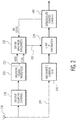
- FIG. 2 shows another specific example approach for providing bandwidth control via line 202 for processing a desired channel from an antenna 110, based in part on processing of an adjacent channel as also depicted in FIG. 1 .
- FIG. 2 shows related signal-flow of an example FM broadcast radio receiver system, also in accordance with the present disclosure and in which one or more of the disclosed embodiments (as with FIG. 1 ) may be implemented. Also as described above in connection with FIG. 1 , similar circuitry may be used such as the above-mentioned SAF4000 from NXP Semiconductors N.V.
- the circuitry of FIG. 2 may also be implemented as a chipset with an integrated software defined-radio approach capable of covering a variety of global broadcast audio standards, including AM/FM, DAB+, DRM(+) and HD
- a bandwidth control system for an FM radio signal uses the antenna 210 to pick up the FM signal at a frequency range corresponding to the spectrum inclusive of the desired FM channel and at least one channel adjacent.
- RF-filtering and amplification circuitry 215 is used to present the FM signals, which are relevant to the frequency range, to a signal-measurement/detection circuit 220.
- the relevant measured signal properties for example, including an indication of FM modulation level of the other (possibly-interfering) channel and the amount of bandwidth (or modulation index), are presented to a bandwidth (BW) control circuit 225 which is used to set the maximum bandwidth based on these measured signal properties.
- BW bandwidth
- an FM signal mixer 230 is used to down convert the received FM signal an intermediate frequency (IF) as is conventional.
- An output of the FM signal mixer 230 provides an IF signal to bandwidth selective/controlling circuitry 235 including, for example, a bandpass filtering circuit.
- bandwidth selective/controlling circuitry 235 including, for example, a bandpass filtering circuit.
- the circuitry 235 uses the maximum bandwidth as provided by the circuit 225, the circuitry 235 provides a selected bandwidth range for the IF signal to be processed by a demodulator 240.
- the demodulator 240 outputs the demodulated signal of the desired channel and is further configured to provide the RF level to the bandwidth (BW) control circuit 225 so as to drive the selection (e.g., dynamically) of whether to use the coarse deviation-estimate approach or the less-coarse deviation-estimate approach, as described above in connection with FIG. 1 .
- BW bandwidth
- the requirements on such bandwidth control systems are less strict as for the wanted channel if nobody is listening to the signal.
- the adjacent channel signal can be distorted by the wanted channel as well as another adjacent channel which may be one channel further away as long as it does not significantly impact the modulation spectrum estimation.
- the bandwidth of the wanted channel is based on the modulation of the adjacent channel.
- Any of a number of methods may be used to measure the adjacent-channel modulation where more reliable detection obviously leads to a more reliable system.
- the broadcasting spectrum is in principle not limited; however, the energy of the signal decreases with a larger distance from the carrier.
- a higher level difference means that for the same amount of measured modulation, a larger part of the spectrum is stronger than the wanted channel and thus does impact the wanted channel; and by combining level indication with modulation index, an increased level of reliability is achieved.
- level indication and modulation of the adjacent channel is the multiplication of level and the modulation values.
- the above-described approaches for estimating deviation has realized impressive results.
- One such system embodiment has been tested successfully with several types of audio (including short audio bursts, with silence in between, wide spectrum audio, etc.).
- the desired channel has been maintained as clean of interference / breakthrough due to the adjacent channel. This has been realized successfully in this clean regard even with the bandwidth, associated with the content of the adjacent channel, fluctuating, and also with: several settings of the signal level difference; testing performed on 100 kHz adjacent channel, 200 kHz adjacent channel and 300 kHz adjacent channel; and where the disturbing channel was at 100 kHz, while an even stronger channel was available at 200 kHz difference.
- exemplary aspects of the disclosure concern processing a desired channel of a frequency modulated (FM) signal based on an indication of an amplitude-level difference between a measured amplitude of a desired channel in the FM broadcast signal and a measured amplitude of another (possibly-interfering) channel. Based on such amplitude-level difference indication, an approach is selected for estimating the frequency spectrum of the other (possibly-interfering) channel in the FM broadcast signal. The selected approach may differ depending on whether the amplitude-level difference corresponds to an amplitude-level difference for which a frequency spectrum of the desired channel may be determined via a coarse estimate or via a less-coarse estimate of the frequency spectrum of the other channel.
- one or more modules are discrete logic circuits or programmable logic circuits configured and arranged for implementing these operations/activities, as may be carried out in the approaches shown and discussed in the instant disclosure.
- a programmable circuit is one or more computer circuits, including memory circuitry for storing and accessing a program to be executed as a set (or sets) of instructions (and/or to be used as configuration data to define how the programmable circuit is to perform), and an algorithm or process as described above is used by the programmable circuit to perform the related steps, functions, operations, activities, etc.
- the instructions (and/or configuration data) can be configured for implementation in logic circuitry, with the instructions (whether characterized in the form of object code, firmware or software) stored in and accessible from a memory (circuit).
Landscapes
- Engineering & Computer Science (AREA)
- Computer Networks & Wireless Communication (AREA)
- Signal Processing (AREA)
- Power Engineering (AREA)
- Circuits Of Receivers In General (AREA)
- Transmitters (AREA)
- Noise Elimination (AREA)
Applications Claiming Priority (1)
| Application Number | Priority Date | Filing Date | Title |
|---|---|---|---|
| US16/804,391 US10999102B1 (en) | 2020-02-28 | 2020-02-28 | FM spectrum estimation relative to adjacent channel |
Publications (1)
| Publication Number | Publication Date |
|---|---|
| EP3873045A1 true EP3873045A1 (fr) | 2021-09-01 |
Family
ID=74666484
Family Applications (1)
| Application Number | Title | Priority Date | Filing Date |
|---|---|---|---|
| EP21157445.4A Withdrawn EP3873045A1 (fr) | 2020-02-28 | 2021-02-16 | Estimation de spectre fm par rapport à un canal adjacent |
Country Status (2)
| Country | Link |
|---|---|
| US (1) | US10999102B1 (fr) |
| EP (1) | EP3873045A1 (fr) |
Families Citing this family (2)
| Publication number | Priority date | Publication date | Assignee | Title |
|---|---|---|---|---|
| US11277162B2 (en) * | 2020-02-28 | 2022-03-15 | Nxp B.V. | Adjacent channel suppression based on adjacent channel properties in FM radio broadcast receivers |
| US11190386B2 (en) | 2020-04-22 | 2021-11-30 | Nxp B.V. | Smart adjacent-channel indicating/scanning for FM modulation |
Citations (2)
| Publication number | Priority date | Publication date | Assignee | Title |
|---|---|---|---|---|
| US6389273B1 (en) * | 1999-08-23 | 2002-05-14 | Delphi Technologies, Inc. | Adjacent channel interference reduction in a FM receiver |
| US20100130152A1 (en) * | 2008-11-26 | 2010-05-27 | Whikehart J William | Automatic bandwidth control with high-deviation detection |
Family Cites Families (7)
| Publication number | Priority date | Publication date | Assignee | Title |
|---|---|---|---|---|
| US4969207A (en) * | 1987-03-20 | 1990-11-06 | Nippon Telegraph And Telephone Corporation | Radio receiver with reception deterioration compensation |
| US5121430C2 (en) * | 1991-02-19 | 2002-09-10 | Quad Dimension Inc | Storm alert for emergencies |
| FR2760845B1 (fr) * | 1997-03-11 | 1999-05-14 | Electricite De France | Dispositif de controle de l'emission de courants porteurs sur un reseau bt |
| US6839388B2 (en) * | 2001-01-22 | 2005-01-04 | Koninklijke Philips Electronics N.V. | System and method for providing frequency domain synchronization for single carrier signals |
| JP3711117B2 (ja) * | 2003-03-25 | 2005-10-26 | 株式会社東芝 | 無線受信装置 |
| WO2015133953A1 (fr) * | 2014-03-07 | 2015-09-11 | Telefonaktiebolaget L M Ericsson (Publ) | Procédé et agencement pour une coordination de brouillage intercellulaire |
| CN107070581B (zh) * | 2016-12-29 | 2019-10-25 | 上海华为技术有限公司 | 一种干扰消除方法以及基站 |
-
2020
- 2020-02-28 US US16/804,391 patent/US10999102B1/en not_active Expired - Fee Related
-
2021
- 2021-02-16 EP EP21157445.4A patent/EP3873045A1/fr not_active Withdrawn
Patent Citations (2)
| Publication number | Priority date | Publication date | Assignee | Title |
|---|---|---|---|---|
| US6389273B1 (en) * | 1999-08-23 | 2002-05-14 | Delphi Technologies, Inc. | Adjacent channel interference reduction in a FM receiver |
| US20100130152A1 (en) * | 2008-11-26 | 2010-05-27 | Whikehart J William | Automatic bandwidth control with high-deviation detection |
Also Published As
| Publication number | Publication date |
|---|---|
| US10999102B1 (en) | 2021-05-04 |
Similar Documents
| Publication | Publication Date | Title |
|---|---|---|
| US8027690B2 (en) | Methods and apparatus for sensing the presence of a transmission signal in a wireless channel | |
| EP1691515B1 (fr) | Controleur et procédé pour preventer reduction de la éfficacité de communication sans fil par utilisation de l'autocorrelation cyclique | |
| US7920839B2 (en) | System and method for station detection and seek in a radio receiver | |
| CN101414847B (zh) | 干扰检测器及干扰检测方法 | |
| US9166637B2 (en) | Impulse noise mitigation under out-of-band interference conditions | |
| JP4581071B2 (ja) | 零if受信機に対する適応相互変調ひずみフィルタ | |
| CN101536328A (zh) | 用于在无线信道中检测传输信号的存在的系统和方法 | |
| US8750804B2 (en) | Applying spurious interference rejection to detect incumbent users of television channels | |
| US20080118011A1 (en) | Accurate signal detection in a wireless environment | |
| EP3873045A1 (fr) | Estimation de spectre fm par rapport à un canal adjacent | |
| US9344202B2 (en) | Received signal quality indicator | |
| KR20150081666A (ko) | 저전력 엔벨로프 검출 수신기에서 간섭 신호를 검출하는 방법 및 장치 | |
| CN113534197A (zh) | 卫星定位信号的干扰检测方法及装置 | |
| US20150049875A1 (en) | Periodogram-based radio signal detection method | |
| US7349499B2 (en) | Accurate signal detection in a wireless environment | |
| EP3873047B1 (fr) | Suppression de canal adjacent basée sur les propriétés de canal adjacent dans des récepteurs de diffusion radio fm | |
| US10862519B1 (en) | Bandwidth control in radio frequency broadcast signals relative to adjacent-channel signal properties | |
| WO2016121393A1 (fr) | Circuit de détection de rapport c/n et circuit de réception de signal | |
| US10734961B2 (en) | Automatic gain controller | |
| US10608759B2 (en) | Method and sensor for detecting the presence of co-channel jamming | |
| US11190386B2 (en) | Smart adjacent-channel indicating/scanning for FM modulation | |
| EP3905534B1 (fr) | Détection de niveau rf pour le canal souhaité parmi plusieurs canaux de diffusion | |
| US8676147B1 (en) | Detection system, controller, and method of detecting a signal of interest | |
| US8139771B1 (en) | System and method for switching a mode of a receiver using block estimation | |
| JP4121410B2 (ja) | 信号検出装置およびその装置を利用可能な受信装置 |
Legal Events
| Date | Code | Title | Description |
|---|---|---|---|
| PUAI | Public reference made under article 153(3) epc to a published international application that has entered the european phase |
Free format text: ORIGINAL CODE: 0009012 |
|
| STAA | Information on the status of an ep patent application or granted ep patent |
Free format text: STATUS: THE APPLICATION HAS BEEN PUBLISHED |
|
| AK | Designated contracting states |
Kind code of ref document: A1 Designated state(s): AL AT BE BG CH CY CZ DE DK EE ES FI FR GB GR HR HU IE IS IT LI LT LU LV MC MK MT NL NO PL PT RO RS SE SI SK SM TR |
|
| STAA | Information on the status of an ep patent application or granted ep patent |
Free format text: STATUS: REQUEST FOR EXAMINATION WAS MADE |
|
| 17P | Request for examination filed |
Effective date: 20220301 |
|
| RBV | Designated contracting states (corrected) |
Designated state(s): AL AT BE BG CH CY CZ DE DK EE ES FI FR GB GR HR HU IE IS IT LI LT LU LV MC MK MT NL NO PL PT RO RS SE SI SK SM TR |
|
| STAA | Information on the status of an ep patent application or granted ep patent |
Free format text: STATUS: EXAMINATION IS IN PROGRESS |
|
| 17Q | First examination report despatched |
Effective date: 20230517 |
|
| STAA | Information on the status of an ep patent application or granted ep patent |
Free format text: STATUS: THE APPLICATION IS DEEMED TO BE WITHDRAWN |
|
| 18D | Application deemed to be withdrawn |
Effective date: 20250902 |