EP3873152B1 - Verfahren und vorrichtungen zum empfang und zum senden von downlink-steuerinformationen - Google Patents
Verfahren und vorrichtungen zum empfang und zum senden von downlink-steuerinformationen Download PDFInfo
- Publication number
- EP3873152B1 EP3873152B1 EP18939033.9A EP18939033A EP3873152B1 EP 3873152 B1 EP3873152 B1 EP 3873152B1 EP 18939033 A EP18939033 A EP 18939033A EP 3873152 B1 EP3873152 B1 EP 3873152B1
- Authority
- EP
- European Patent Office
- Prior art keywords
- sub
- bands
- access network
- network device
- terminal
- Prior art date
- Legal status (The legal status is an assumption and is not a legal conclusion. Google has not performed a legal analysis and makes no representation as to the accuracy of the status listed.)
- Active
Links
Images


Classifications
-
- H—ELECTRICITY
- H04—ELECTRIC COMMUNICATION TECHNIQUE
- H04L—TRANSMISSION OF DIGITAL INFORMATION, e.g. TELEGRAPHIC COMMUNICATION
- H04L5/00—Arrangements affording multiple use of the transmission path
- H04L5/003—Arrangements for allocating sub-channels of the transmission path
- H04L5/0053—Allocation of signalling, i.e. of overhead other than pilot signals
-
- H—ELECTRICITY
- H04—ELECTRIC COMMUNICATION TECHNIQUE
- H04L—TRANSMISSION OF DIGITAL INFORMATION, e.g. TELEGRAPHIC COMMUNICATION
- H04L27/00—Modulated-carrier systems
- H04L27/0006—Assessment of spectral gaps suitable for allocating digitally modulated signals, e.g. for carrier allocation in cognitive radio
-
- H—ELECTRICITY
- H04—ELECTRIC COMMUNICATION TECHNIQUE
- H04L—TRANSMISSION OF DIGITAL INFORMATION, e.g. TELEGRAPHIC COMMUNICATION
- H04L5/00—Arrangements affording multiple use of the transmission path
- H04L5/0001—Arrangements for dividing the transmission path
- H04L5/0003—Two-dimensional division
- H04L5/0005—Time-frequency
- H04L5/0007—Time-frequency the frequencies being orthogonal, e.g. OFDM(A) or DMT
- H04L5/001—Time-frequency the frequencies being orthogonal, e.g. OFDM(A) or DMT the frequencies being arranged in component carriers
-
- H—ELECTRICITY
- H04—ELECTRIC COMMUNICATION TECHNIQUE
- H04W—WIRELESS COMMUNICATION NETWORKS
- H04W72/00—Local resource management
- H04W72/04—Wireless resource allocation
- H04W72/044—Wireless resource allocation based on the type of the allocated resource
- H04W72/0453—Resources in frequency domain, e.g. a carrier in FDMA
-
- H—ELECTRICITY
- H04—ELECTRIC COMMUNICATION TECHNIQUE
- H04W—WIRELESS COMMUNICATION NETWORKS
- H04W72/00—Local resource management
- H04W72/20—Control channels or signalling for resource management
-
- H—ELECTRICITY
- H04—ELECTRIC COMMUNICATION TECHNIQUE
- H04W—WIRELESS COMMUNICATION NETWORKS
- H04W72/00—Local resource management
- H04W72/20—Control channels or signalling for resource management
- H04W72/23—Control channels or signalling for resource management in the downlink direction of a wireless link, i.e. towards a terminal
-
- H—ELECTRICITY
- H04—ELECTRIC COMMUNICATION TECHNIQUE
- H04W—WIRELESS COMMUNICATION NETWORKS
- H04W74/00—Wireless channel access
- H04W74/08—Non-scheduled access, e.g. ALOHA
- H04W74/0808—Non-scheduled access, e.g. ALOHA using carrier sensing, e.g. carrier sense multiple access [CSMA]
-
- Y—GENERAL TAGGING OF NEW TECHNOLOGICAL DEVELOPMENTS; GENERAL TAGGING OF CROSS-SECTIONAL TECHNOLOGIES SPANNING OVER SEVERAL SECTIONS OF THE IPC; TECHNICAL SUBJECTS COVERED BY FORMER USPC CROSS-REFERENCE ART COLLECTIONS [XRACs] AND DIGESTS
- Y02—TECHNOLOGIES OR APPLICATIONS FOR MITIGATION OR ADAPTATION AGAINST CLIMATE CHANGE
- Y02D—CLIMATE CHANGE MITIGATION TECHNOLOGIES IN INFORMATION AND COMMUNICATION TECHNOLOGIES [ICT], I.E. INFORMATION AND COMMUNICATION TECHNOLOGIES AIMING AT THE REDUCTION OF THEIR OWN ENERGY USE
- Y02D30/00—Reducing energy consumption in communication networks
- Y02D30/70—Reducing energy consumption in communication networks in wireless communication networks
Definitions
- the present disclosure relates to the field of communications, and more particularly, to a Downlink Control Information (DCI) receiving method, a DCI transmitting method, a terminal and an access network device.
- DCI Downlink Control Information
- the terminal may monitor a Physical Downlink Control Channel (PDCCH) transmitted by the base station on the activated BWP and blindly detect the DCI. Then, the terminal may receive the downlink data transmitted by the base station on Physical Downlink Shared Channel (PDSCH) according to the received DCI, or transmit the uplink data to the base station through Physical Uplink Shared Channel (PUSCH) according to the received DCI.
- PDCCH Physical Downlink Control Channel
- PUSCH Physical Uplink Shared Channel
- NR-U 5G New Radio Unlicensed
- LBT Listen Before Talk
- US 2018/0279289 A1 describes a system and a method for signalling of resource allocation for one or more numerologies.
- US 2020/0112484 A1 describes techniques related to improved methods, systems, devices, and apparatuses that support subband usage dependent downlink signals and channels.
- the described techniques are provided for identifying a bandwidth part (BWP) configuration for a user equipment (UE), where the BWP configuration indicates a set of frequency resources of a shared radio frequency (RF) spectrum band.
- BWP bandwidth part
- UE user equipment
- the embodiments of the application provide a downlink control information receiving method, a DCI transmitting method, a terminal and an access network device.
- the invention is set out in the appended set of claims.
- the access network device By dividing one BWP into m sub-bands, after performing LBT on the m sub-bands, the access network device firstly transmits the target sequence on the n sub-bands on which the LBT is successful, and then transmits the DCI. After the target sequence is monitored, the terminal monitors the DCI on all or part of the m sub-bands, thereby effectively reducing the search times and power consumption of the terminal on the PDCCH, and avoiding unnecessary power and battery consumption of the terminal.
- FIG. 1 is a schematic diagram illustrating a mobile communication system not being part of the invention.
- the mobile communication system may include an access network device 110 and a terminal 120.
- the access network device 110 is deployed in an access network.
- the access network in the 5G NR system may be referred to as NG-RAN (New Generation-Radio Access Network).
- the access network device 110 and the terminal 120 communicate with each other via a certain type of air interface technology, for example, may communicate with each other via cellular technology.
- the access network device 110 is a device deployed in the access network to provide wireless communication function for the terminal 120.
- the access network device 110 may include various forms of macro base stations, micro base stations, relay stations, access points, and the like.
- the names of devices having base station functions may vary, for example, in the 5G NR system, referred to as gNodeB or gNB. With the evolution of communication technologies, the name "base station" may change.
- a base station For convenience of description, in the present embodiments of the present disclosure, the above-described devices for providing a wireless communication function for the terminal 120 are collectively referred to as a base station.
- the number of terminal 120 is typically plural, and one or more terminals 120 may be distributed within a cell managed by each access network device 110.
- the terminal 120 may include various types of handheld devices, vehicle-mounted devices, wearable devices, computing devices, that having wireless communication functions, or other processing devices connected to a wireless modem, as well as various forms of User Equipment (UE), Mobile Station (MS), Terminal Device, and the like.
- UE User Equipment
- MS Mobile Station
- Terminal Device and the like.
- the above-mentioned devices are collectively referred to as a terminal.
- the "5G NR system" in the embodiments of the present disclosure may also be referred to as a 5G system or an NR system, and the meaning thereof will be understood by the person skilled in the art.
- the technical solution described in the embodiments of the present disclosure may be applicable to the 5G NR system, may also be applicable to a subsequent evolution system of the 5G NR system.
- the access network device 110 and the terminal 120 may communicate with each other by utilizing an unlicensed spectrum. That is, the access network device 110 and the terminal 120 may be the access network device 110 and the terminal 120 in a scenario of the NR-U independent networking.
- FIG. 2 illustrates a flowchart of a method for receiving the DCI according to an exemplary embodiment of the present disclosure.
- the method may be applied to the communication system illustrated in FIG. 1 , the method includes the following steps.
- the access network device transmits BWP configuration information to the terminal.
- the access network device sends a Radio Resource Control (RRC) message to the terminal, and the RRC message carries the BWP configuration information.
- RRC Radio Resource Control
- the terminal determines the target BWP located in the unlicensed spectrum according to the BWP configuration information.
- the terminal also determines the m sub-bands according to the BWP configuration information.
- the division information for the m sub-bands is carried in the BWP configuration information, or the division information for the m sub-bands is predefined by the communication protocol, or the division information for the m sub-bands is transmitted by the access network device through other control information.
- the access network device Since the m sub-bands are unlicensed spectrum, the access network device needs to perform LBT on the m sub-bands respectively to determine whether each of the m sub-bands is occupied.
- the n target sub-bands are all sub-bands on which the LBT is successful among the m sub-bands.
- the n target sub-bands are sub-bands for transmitting downlink DCI, and the n target sub-bands are all or part of the sub-bands on which the LBT is successful.
- the access network device transmits a target sequence on the n target sub-bands.
- the target sequence may be a pseudo-random sequence that occupies relatively few time-frequency resources. For example, the target sequence occupies only one symbol in the time domain.
- the time domain position for transmitting the target sequence is pre-determined by the communication protocol. For example, when there needs the transmission, the transmission is performed on the first symbol of each sub-frame.
- the terminal monitors the target sequence on the m sub-bands respectively.
- the terminal monitors the target sequence on each of the m sub-bands respectively, and determines several sub-bands on which the target sequence is successfully monitored.
- the access network device transmits DCI to the terminal on the n target sub-bands.
- the access network device by dividing the BWP into m sub-bands, after performing LBT on the m sub-bands, the access network device firstly transmits a target sequence on n sub-bands on which LBT is successful, and then transmits DCI on the n sub-bands on which LBT is successful. After the target sequence is monitored, the terminal monitors the DCI on all or part of the m sub-bands, thereby effectively reducing the search times and the search power consumption of the terminal on the PDCCH, and avoiding unnecessary power and battery consumption of the terminal.
- the target sequence has different meanings.
- the target sequence is used to trigger the terminal to receive DCI in the PDCCH.
- the target sequence is used to identify the sub-bands on which LBT is successful, i.e., the available sub-bands.
- the target sequence is used to identify the sub-bands on which the DCI is transmitted.
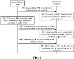
- FIG. 4 illustrates a flowchart of a method for receiving the DCI according to another exemplary embodiment of the present disclosure.
- the method may be applied to the communication system illustrated in FIG. 1 , the method includes the following steps.
- the access network device transmits BWP configuration information to the terminal.
- the BWP configuration information is used for configuring the target BWP which is located in the unlicensed spectrum and includes m sub-bands.
- the target BWP is one BWP, and the target BWP may be an uplink BWP and/or a downlink BWP.
- the target BWP is a BWP belonging to the unlicensed spectrum.
- the target BWP includes m sub-bands, and m is a positive integer greater than 1.
- m is 2, 3, 4, 5, 6, 8, etc.
- the m sub-bands are consecutive in the frequency domain. That is, the m sub-bands are consecutive m sub-bands in the frequency domain.
- the access network device sends an RRC message to the terminal, and the RRC message carries the BWP configuration information.
- the BWP configuration information is semi-static configuration information.
- the semi-static configuration information refers to keep using the current configuration information before the configuration information transmitted next time is received.
- the terminal receives the BWP configuration information transmitted by the access network device, and determines m sub-bands of the target BWP according to the BWP configuration information.
- the terminal receives the RRC message transmitted by the access network device, and acquires the BWP configuration information from the RRC message.
- the terminal determines the target BWP located in the unlicensed spectrum according to the BWP configuration information.
- the terminal also determines the m sub-bands according to the BWP configuration information.
- the access network device performs LBT on the m sub-bands and determines n target sub-bands according to a LBT result.
- the access network device Since the m sub-bands are unlicensed spectrum, the access network device needs to perform LBT on the m sub-bands respectively to determine whether each of the m sub-bands is occupied.
- the access network device determines at least one of the m sub-bands as the target sub-band when the LBT result is that there is one sub-band that is an unoccupied sub-band.
- the access network device determines the n target sub-bands in the k sub-bands on which LBT is successful.
- m, k, and n are all positive integers, k is not greater than m, and n is not greater than k.
- the access network device determines one of the k sub-bands (or part of the k sub-bands) as the target sub-band. For example, the access network device determines any one of the k sub-bands as the target sub-band, determines the first sub-band as the target sub-band, or determines the last sub-band as the target sub-band.
- the access network device transmits a target sequence at the first time domain position on the n target sub-bands.
- the terminal monitors the target sequence at the first time domain position on the m sub-bands respectively.
- the access network device transmits DCI to the terminal on the n target sub-bands.
- the terminal monitors the DCI on each of the m sub-bands after the target sequence is monitored.
- the terminal monitors the DCI on all of the m sub-bands.
- the terminal pre-receives the CORESET for the m sub-bands transmitted by the access network device, and determines the candidate time-frequency resource positions of the PDCCH according to the CORESET, so as to determine the search space of the PDCCH, and then performs blind detection and reception of the DCI according to the search space of the PDCCH.
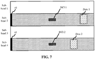
- the access network device configures four sub-bands for the terminal, and LBT is successful on the sub-band 2 and the sub-band 4, that is, the sub-band 2 and the sub-band 4 are not occupied, and the sub-band 1 and the sub-band 3 are occupied.
- the access network device may determine the sub-band 2 as the target sub-band, and transmit the target sequence 41 on a first symbol of the sub-band 2.
- the first symbol is the time domain position which is pre-determined by the communication protocol.
- the terminal is prepared to receive the DCI after the target sequence 41 is monitored on the sub-band 2.
- the access network device transmits a DCI 1 on the sub-band 2, and the terminal receives or transmits data 1 on the sub-band 2 according to the DCI 1 after the DCI 1 is received on the sub-band 2.
- the access network device transmits a DCI 2 on the sub-band 4, and the terminal receives or transmits a data 2 on the sub-band 4 according to the DCI 2 after the DCI 2 is received on the sub-band 4.
- the terminal after the access network device transmits the target sequence on the target sub-band, the terminal is prepared to receive the DCI only after the target sequence is monitored. That is, the target sequence is used for triggering the terminal to start receiving the DCI, so that the access network device and the terminal only need to activate one BWP.
- the terminal when the target sequence is not transmitted due to that LBT performed by the access network device on all sub-bands fails, the terminal does not need to perform blind detection for the PDCCH, thereby effectively reducing the search times and search power consumption of the terminal on the PDCCH, and avoiding unnecessary power and battery consumption of the terminal.
- FIG. 6 illustrates a flowchart of a method for receiving the DCI according to another exemplary embodiment of the present disclosure.
- the method may be applied to the communication system illustrated in FIG. 1 , the method includes the following steps.
- the access network device transmits BWP configuration information to the terminal.
- the BWP configuration information is used to configure the target BWP which is located in the unlicensed spectrum and includes m sub-bands.
- the target BWP is one BWP, and the target BWP may be an uplink BWP and/or a downlink BWP.
- the target BWP is a BWP belonging to the unlicensed spectrum.
- the m sub-bands are consecutive in the frequency domain. That is, the m sub-bands are consecutive m sub-bands in the frequency domain.
- the target BWP includes m sub-bands, and m is a positive integer greater than 1.
- m is 2, 3, 4, 5, 6, 8, etc.
- the access network device transmits an RRC message to the terminal, and the RRC message carries the BWP configuration information.
- the BWP configuration information is semi-static configuration information.
- the semi-static configuration information refers to keep using the current configuration information before the configuration information transmitted next time is received.
- the terminal receives the BWP configuration information transmitted by the access network device, and determines m sub-bands of the target BWP according to the BWP configuration information.
- the terminal determines the target BWP located in the unlicensed spectrum according to the BWP configuration information.
- the terminal also determines m sub-bands according to the BWP configuration information.
- the division information for the m sub-bands is carried in the BWP configuration information, or the division information for the m sub-bands is predefined by the communication protocol, or the division information for the m sub-bands is transmitted by the access network device through other control information.
- the access network device transmits a CORESET for the m sub-bands to the terminal.
- the terminal receives the CORESET for the m sub-bands transmitted by the access network device.
- the terminal receives the CORESET for the m sub-bands transmitted by the access network device, and determines the candidate time-frequency resource positions of the PDCCH according to the CORESET.
- the access network device performs LBT on the m sub-bands and determines n sub-bands on which the LBT is successful as the n target sub-bands.
- the access network device Since the m sub-bands are unlicensed spectrum, the access network device needs to perform LBT on the m sub-bands respectively to determine whether each of the m sub-bands is occupied.
- the access network device determines all of the n sub-bands as the target sub-bands when the LBT result is that there are n sub-bands that are unoccupied sub-bands.
- the access network device transmits a target sequence at the first time domain position on the n target sub-bands.
- the terminal monitors the target sequence at the first time domain position on the m sub-bands respectively, and determines the n sub-bands on which the target sequence has been monitored.
- the terminal determines that the target sub-band is a sub-band on which LBT is successful.
- the access network device transmits DCI to the terminal on at least one of the n target sub-bands.
- the access network device only transmits the DCI on part of the n target sub-bands.
- the DCI carries the scheduling information for the time-frequency resource of the n target sub-bands.
- the terminal monitors the DCI on at least one of the n target sub-bands after the target sequence is monitored.
- the terminal determines the search space of the PDCCH on the n target sub-bands according to the CORESET, the DCI on the n target sub-bands is received by blind detection according to the search space of the PDCCH.
- the access network device configures four sub-bands for the terminal, and LBT is successful on the sub-band 2 and the sub-band 4, that is, the sub-band 2 and the sub-band 4 are not occupied, and the sub-band 1 and the sub-band 3 are occupied.
- the access network device may determine the sub-band 2 and the sub-band 4 as the target sub-bands, and transmit the target sequence 41 on the first symbol of the sub-band 2 and the sub-band 4.
- the first symbol is the time domain position which is pre-determined by the communication protocol.
- the terminal is prepared to receive the DCI on the sub-band 2 and the sub-band 4 after the target sequence 41 is monitored on the sub-band 2 and the sub-band 4.
- the access network device transmits a DCI 1 on the sub-band 2, and the terminal receives or transmits data 1 on the sub-band 2 according to the DCI 1 after the DCI 1 is received on the sub-band 2.
- the access network device transmits a DCI 2 on the sub-band 4, and the terminal receives or transmits a data 2 on the sub-band 4 according to the DCI 2 after the DCI 2 is received on the sub-band 4.
- the access network device determines the n target sub-bands on which LBT is successful, and transmits the target sequence on the n target sub-bands.
- the terminal can learn the n target sub-bands on which LBT is successful after the target sub-bands is monitored, and is prepared to receive the DCI only on the n target sub-bands, so that the access network device and the terminal only need to activate one BWP.
- the access network device only needs to transmit the target sequence on the n target sub-bands, and the terminal only needs to perform blind detection for the PDCCH on the n target sub-bands, thereby effectively reducing the search times and the search power consumption of the terminal on the PDCCH, and avoiding unnecessary power and battery consumption of the terminal.
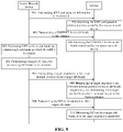
- FIG. 9 illustrates a flowchart of a method for receiving the DCI according to another exemplary embodiment of the present disclosure.
- the method may be applied to the communication system illustrated in FIG. 1 , the method includes the following steps.
- the access network device transmits BWP configuration information to the terminal.
- the access network device sends an RRC message to the terminal, and the RRC message carries the BWP configuration information.
- the BWP configuration information is semi-static configuration information.
- the semi-static configuration information refers to keep using the current configuration information before the configuration information transmitted next time is received.
- the terminal receives the BWP configuration information transmitted by the access network device, and determines m sub-bands of the target BWP according to the BWP configuration information.
- the terminal receives the RRC message transmitted by the access network device, and acquires the BWP configuration information from the RRC message.
- the terminal determines the target BWP located in the unlicensed spectrum according to the BWP configuration information.
- the terminal also determines m sub-bands according to the BWP configuration information.
- the division information for the m sub-bands is carried in the BWP configuration information, or the division information for the m sub-bands is predefined by the communication protocol, or the division information for the m sub-bands is transmitted by the access network device through other control information.
- the access network device transmits a CORESET for the m sub-bands to the terminal.
- the terminal receives the CORESET for the m sub-bands transmitted by the access network device.
- the terminal receives the CORESET for the m sub-bands transmitted by the access network device, and determines the candidate time-frequency resource positions of the PDCCH according to the CORESET.
- the access network device Since the m sub-bands are unlicensed spectrum, the access network device needs to perform LBT on the m sub-bands respectively to determine whether each of the m sub-bands is occupied.
- the access network device determines the n target sub-bands for transmitting DCI from the k sub-bands.
- the access network device determines the n target sub-bands from the k sub-bands on which the LBT is successful.
- m, k, and n are all positive integers, k is not greater than m, and n is not greater than k.
- the n target sub-bands are sub-bands for transmitting DCI.
- the access network device transmits a target sequence at the first time domain position on the n target sub-bands.
- the target sequence may be a pseudo-random sequence that occupies relatively few time-frequency resources. For example, the target sequence occupies only one symbol in the time domain.
- the first time domain position for transmitting the target sequence is pre-determined by the communication protocol. For example, when there needs the transmission, the transmission is performed on the first symbol of each sub-frame.
- the first time domain position is pre-configured by the access network device during the configuration of the target BWP.
- the first time domain position is carried in the BWP configuration information.
- the terminal monitors the target sequence at the first time domain position on the m sub-bands respectively, and determines the n sub-bands on which the target sequence has been monitored.
- the terminal determines that the target sub-band is a sub-band on which the LBT is successful.
- the access network device transmits DCI to the terminal on the n target sub-bands.
- the access network device transmits the DCI on each of the n target sub-bands.
- DCI on each sub-band carries the scheduling information for time-frequency resources on the sub-band.
- the DCI on the n target sub-bands carries the scheduling information for time-frequency resources on the k target sub-bands.
- the terminal monitors DCI on the n target sub-bands after the target sequence is monitored.
- the terminal determines the search space of the PDCCH on the n target sub-bands according to CORESET, the DCI on the n target sub-bands is received by blind detection according to the search space of the PDCCH.
- the access network device configures four sub-bands for the terminal, and LBT is successful on the sub-band 2, the sub-band 3 and the sub-band 4, that is, the sub-band 2, the sub-band 3 and the sub-band 4 are not occupied, and the sub-band 1 is occupied.
- the access network device may determine the sub-band 3 and the sub-band 4 as the target sub-bands, and transmits the target sequence 41 on the first symbol of the sub-band 3 and the sub-band 4.
- the first symbol is the time domain position which is pre-determined by the communication protocol.
- the terminal is prepared to receive the DCI on the sub-band 3 and the sub-band 4 after the target sequence 41 is monitored on the sub-band 3 and the sub-band 4.
- the access network device transmits the DCI on the sub-band 3 and the sub-band 4, and the terminal receives or transmits data on the sub-band 2, the sub-band 3 and the sub-band 4 according to the DCI after the DCI is received on the sub-band 3 and the sub-band 4.
- the access network device determines the n target sub-bands from the k sub-bands on which LBT is successful, and transmits the target sequence on the n target sub-bands.
- the terminal can learn the n target sub-bands on which LBT is successful after the target sub-bands is monitored by the terminal, and the terminal is prepared to receive the DCI only on the n target sub-bands, so that the access network device and the terminal only need to activate one BWP.
- the access network device only needs to transmit the target sequence on the n target sub-bands, and the terminal only needs to perform blind detection for the PDCCH on the n target sub-bands, thereby effectively reducing the search times and the search power consumption of the terminal on the PDCCH, and avoiding unnecessary power and battery consumption of the terminal.
- the processing module 1140 is configured to monitor DCI on all or part of the m sub-bands after the target sequence is monitored.
- n is a positive integer greater than 1.
- the m sub-bands are consecutive in the frequency domain.
- the processing module 1140 is configured to monitor the DCI on each of the m sub-bands.
- the processing module 1140 is configured to determine n target sub-bands on which the target sequence has been monitored, n being a positive integer not greater than m, and to monitor the DCI on at least one of the n target sub-bands.
- the target sequence is transmitted by the access network device on the target sub-bands on which LBT is successful, or the target sequence is transmitted by the access network device on a target sub-band transmitting the DCI.
- the receiving module is configured to receive a control resource set for the m sub-bands from the access network device.
- the processing module 1140 is configured to determine PDCCH search positions on the n target sub-bands according to the control resource set for the m sub-bands, the search positions on the n target sub-bands having different frequency domain positions and same time domain position, and to monitor the DCI at the PDCCH search positions.
- the processing module 1140 is configured to monitor the target sequence at a first time domain position on all or part of the m sub-bands respectively.
- the first time domain position is a time-frequency position which is pre-determined by a communication protocol, or the first time domain position is a time domain position which is pre-configured by the access network device during a procedure of configuring the target BWP.
- the BWP configuration information is semi-static configuration information.
- FIG. 12 is a block diagram of a device for transmitting DCI not being part of the invention.
- the device for transmitting DCI may be implemented as part or all of a server in software, hardware, or a combination of both.
- the device for transmitting DCI may include:
- the transmitting module 1220 is configured to transmit a target sequence on the n target sub-bands.
- the transmitting module 1220 is configured to transmit DCI to the terminal on all or part of the m sub-bands.
- n is a positive integer not greater than m.
- the m sub-bands are consecutive in the frequency domain.
- the processing module 1240 is configured to perform the LBT on the m sub-bands, and determine the n sub-bands on which the LBT is successful as the n target sub-bands.
- the processing module 1240 is configured to perform the LBT on the m sub-bands and determine k sub-bands on which the LBT is successful,. and to determine n target sub-bands for transmitting the DCI from the k sub-bands.
- the transmitting module 1220 is configured to transmit the DCI to the terminal on each of the m sub-bands.
- the transmitting module 1220 is configured to transmit the DCI to the terminal on all or part of the n target sub-bands.
- the transmitting module 1220 is configured to transmit the DCI to the terminal on each of the n target sub-bands, the DCI being used for scheduling a time-frequency resource on the k sub-bands.
- the transmitting module 1220 is configured to transmit a control resource set for the m sub-bands to the terminal.
- the transmitting module 1220 is configured to transmit the target sequence at a first time domain position on the n sub-bands respectively;
- the first time domain position is a time-frequency position which is predefined by a communication protocol, or the first time domain position is a time domain position which is pre-configured by the access network device during a procedure of configuring the target BWP.
- the access network device and the terminal include corresponding hardware modules and/or software modules for performing various functions.
- the embodiments of the present disclosure can be implemented in hardware or a combination of hardware and computer software. Whether a function is performed in hardware or computer software-driven hardware depends on the particular application and design constraints of the technical solution. Those skilled in the art may use different methods to implement the described functions for each particular application, but such implementation should not be considered to beyond the scope of the technical solutions of the embodiments of the present disclosure.
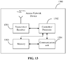
- FIG. 13 is a schematic structural diagram illustrating an access network device according to an exemplary embodiment.
- the access network device 1300 includes a transmitter/receiver 1301 and a processor 1302.
- the processor 1302 may also be a controller, illustrated in FIG. 13 as "controller/processor 1302".
- the transmitter/receiver 1301 is configured to support the transmission and reception of information between the access network device and the terminal in the above embodiments, and to support the communication between the access network device and other network entities.
- the processor 1302 performs various functions for communicating with the terminal.
- On the uplink an uplink signal from the terminal is received via an antenna, demodulated by the receiver 1301 (e.g., demodulating a high frequency signal into a baseband signal), and further processed by the processor 1302 to recover the business data and signaling message transmitted by the terminal.
- the business data and signaling message are processed by the processor 1302, modulated by the transmitter 1301 (e.g., modulating a baseband signal into a high frequency signal) to generate a downlink signal, and transmitted to the terminal via an antenna.
- the demodulation or modulation function described above may also be performed by the processor 1302.
- the processor 1302 is further configured to perform various steps on the access network device side in the above method embodiments, and/or other steps of the technical solution described in the embodiments of the present disclosure.
- the access network device 1300 may further include a memory 1303 for storing program code and data of the access network device 1300.
- the access network device 1300 may further include a communication unit 1304.
- the communication unit 1304 is configured to support the access network device 1300 to communicate with other network entities (for example, network device in the core network).
- the communication unit 1304 may be a NG-U interface for supporting the communication between the access network device 1300 and a UPF (User Plane Function) entity.
- the communication unit 1304 may be an NG-C interface for supporting the communication between the access network device 1300 and an AMF (Access and Mobility Management Function) entity.
- FIG. 14 is a schematic structural diagram illustrating a terminal according to an exemplary embodiment.
- the terminal 1400 includes a transmitter 1401, a receiver 1402, and a processor 1403.
- the processor 1403 may also be a controller, illustrated in FIG. 6 as "controller/processor 1403".
- the terminal 1400 may further include a modem processor 1405.
- the modem processor 1405 may include an encoder 1406, a modulator 1407, a decoder 1408, and a demodulator 1409.
- the transmitter 1401 regulates (for example, analog converts, filters, amplifies, and upconverts, etc.) the output samples and generates an uplink signal that is transmitted via an antenna to the access network device described in the above embodiments.
- the antenna receives the downlink signal transmitted by the access network device in the above embodiment.
- Receiver 1402 regulates (for example, filters, amplifies, downconverts, digitizes, etc.) the signal received from the antenna and provides input samples.
- the encoder 1406 receives the business data and signaling message to be transmitted on the uplink, and processes (for example, formats, encodes, and interleaves) the business data and signaling message.
- the processor 1403 controls and manages the operation of the terminal 1400 to perform the processing performed by the terminal 1400 in the above embodiment of the present disclosure.
- the processor 1403 is further configured to perform various steps of the terminal side in the above method embodiments, and/or other steps of the technical solution described in the embodiments of the present disclosure.
- the terminal 1400 may further include a memory 1404 for storing the program code and data for the terminal 1400.
- FIG. 14 illustrates only a simplified design of the terminal 1400.
- terminal 1400 may include any number of transmitters, receivers, processors, modem processors, memories, and the like. All terminals that may implement embodiments of the present disclosure are within the scope of the embodiments of the present disclosure.
- a non-transitory computer readable storage medium having stored thereon a computer program that, when executed by the processor of the terminal, implements the DCI receiving method on the terminal side as described above.
- a computer program product having stored thereon a computer program that, when executed by the processor of the access network device, implements the DCI transmitting method on the access network device side as described above.
- a computer program product having stored thereon a computer program that, when executed by the processor of the terminal, implements the DCI receiving method on the terminal side as described above.
Landscapes
- Engineering & Computer Science (AREA)
- Signal Processing (AREA)
- Computer Networks & Wireless Communication (AREA)
- Physics & Mathematics (AREA)
- Health & Medical Sciences (AREA)
- General Health & Medical Sciences (AREA)
- Spectroscopy & Molecular Physics (AREA)
- Mobile Radio Communication Systems (AREA)
Claims (14)
- Verfahren zum Empfang von Downlink-Kontrollinformationen (DCI), umfassend:Empfangen (202), durch ein Endgerät, von Bandbreitenteil-, BWP-, Konfigurationsinformationen, die von einer Zugangsnetzwerkvorrichtung übertragen werden, wobei die BWP-Konfigurationsinformationen zum Konfigurieren eines Ziel-BWP verwendet werden, der sich in einem unlizenzierten Spektrum befindet und m Teilbänder umfasst;Bestimmung (202) der m Teilbänder, die sich am Ziel-BWP befinden, durch das Endgerät entsprechend den BWP-Konfigurationsinformationen;dadurch gekennzeichnet, dass das Verfahren weiter Folgendes umfasst:Überwachung (205) einer Zielsequenz an einer ersten Zeitbereichsposition auf allen oder einem Teil der m Teilbänder durch das Endgerät, wobei die erste Zeitbereichsposition eine Zeit-Frequenz-Position ist, die durch ein Kommunikationsprotokoll vorbestimmt ist, oder die erste Zeitbereichsposition eine Zeitbereichsposition ist, die durch die Zugangsnetzwerkvorrichtung während einer Prozedur zum Konfigurieren des Ziel-BWP vorkonfiguriert ist; und die Zielsequenz verwendet wird, um Teilbänder zu identifizieren, auf denen Listen Before Talk, LBT, in den m Teilbändern gelingt, oder die Zielsequenz verwendet wird, um Teilbänder zu identifizieren, auf denen die DCI in den m Teilbändern übertragen wird;Überwachung (207) von DCI auf allen oder einem Teil der m Teilbänder durch das Endgerät, nachdem die Zielsequenz überwacht wurde;wobei m eine positive ganze Zahl größer als 1 ist.
- Verfahren nach Anspruch 1, wobei die Überwachung (207) der DCI auf allen oder einem Teil der m Teilbänder durch das Endgerät Folgendes umfasst:
Überwachung der DCI auf jedem der m Teilbänder durch das Endgerät. - Verfahren nach Anspruch 1, wobei die Überwachung (207) der DCI auf allen oder einem Teil der m Teilbänder durch das Endgerät Folgendes umfasst:Bestimmung von n Zielteilbändern durch das Endgerät, auf denen die Zielsequenz überwacht wurde, wobei n eine positive ganze Zahl nicht größer als m ist;Überwachung der DCI auf mindestens einem der n Zielteilbänder durch das Endgerät;wobei die Zielsequenz von der Zugangsnetzwerkvorrichtung auf den Zielteilbändern übertragen wird, wenn Listen Before Talk, LBT, gelingt, oder wobei die Zielsequenz von der Zugangsnetzwerkvorrichtung auf einem Zielteilband übertragen wird, das die DCI überträgt.
- Verfahren nach Anspruch 3, weiter umfassend:Empfangen eines Kontrollressourcensatzes für die m Teilbänder von der Zugangsnetzwerkvorrichtung durch das Endgerät;wobei die Überwachung der DCI auf mindestens einem der n Zielteilbänder durch das Endgerät Folgendes umfasst:Bestimmen von Suchpositionen für den physikalischen Downlink-Kontrollkanal (PDCCH) auf den n Zielteilbändern durch das Endgerät entsprechend der für die m Teilbänder eingestellten Kontrollressourcen, wobei die PDCCH-Suchpositionen auf den n Zielteilbändern unterschiedliche Frequenzbereichspositionen und dieselbe Zeitbereichsposition aufweisen; undÜberwachung der DCI an den PDCCH-Suchpositionen durch das Endgerät.
- Verfahren nach einem der Ansprüche 1 bis 4, wobei die BWP-Konfigurationsinformationen halbstatische Konfigurationsinformationen sind.
- Verfahren nach einem der Ansprüche 1 bis 5, wobei die m Teilbänder in einem Frequenzbereich aufeinander folgen.
- Verfahren zur Übertragung von Downlink-Kontrollinformationen (DCI), umfassend:Übertragung (201) von Bandbreitenteil-, BWP-, Konfigurationsinformationen an ein Endgerät durch eine Zugangsnetzwerkvorrichtung, wobei die BWP-Konfigurationsinformationen zum Konfigurieren eines Ziel-BWP verwendet werden, der sich in einem unlizenzierten Spektrum befindet und m Teilbänder umfasst;Durchführen (203) von Listen Before Talk (LBT) in den m Teilbändern durch die Zugangsnetzwerkvorrichtung und Bestimmen von n Zielteilbändern aus den m Teilbändern entsprechend einem LBT-Ergebnis durch die Zugangsnetzwerkvorrichtung;dadurch gekennzeichnet, dass das Verfahren weiter Folgendes umfasst:Übertragung (204), durch die Zugangsnetzwerkvorrichtung, einer Zielsequenz an einer ersten Zeitbereichsposition auf den n Zielteilbändern, wobei die erste Zeitbereichsposition eine Zeit-Frequenz-Position ist, die durch ein Kommunikationsprotokoll vorbestimmt ist, oder die erste Zeitbereichsposition eine Zeitbereichsposition ist, die durch die Zugangsnetzwerkvorrichtung während einer Prozedur zum Konfigurieren des Ziel-BWP vorkonfiguriert ist; und die Zielsequenz verwendet wird, um Teilbänder zu identifizieren, auf denen Listen Before Talk, LBT, in den m Teilbändern gelingt, oder die Zielsequenz verwendet wird, um Teilbänder zu identifizieren, auf denen die DCI in den m Teilbändern übertragen wird;Übertragung (206) von DCI durch die Zugangsnetzwerkvorrichtung an das Endgerät auf allen oder einem Teil der m Teilbänder;wobei m eine positive ganze Zahl größer als 1 ist und n eine positive ganze Zahl nicht größer als m ist.
- Verfahren nach Anspruch 7, wobei das Durchführen (203) des LBT an den m Teilbändern durch die Zugangsnetzwerkvorrichtung und das Bestimmen der n Zielteilbänder aus den m Teilbändern entsprechend dem LBT-Ergebnis durch die Zugangsnetzwerkvorrichtung weiterhin Folgendes umfasst:
Durchführen des LBT auf den m Teilbändern durch die Zugangsnetzwerkvorrichtung und Bestimmen von n Teilbändern, auf denen LBT gelingt, als n Zielteilbändern durch die Zugangsnetzwerkvorrichtung. - Verfahren nach Anspruch 7, wobei das Durchführen (203) des LBT an den m Teilbändern durch die Zugangsnetzwerkvorrichtung und das Bestimmen von n Zielteilbändern aus den m Teilbändern entsprechend einem LBT-Ergebnis durch die Zugangsnetzwerkvorrichtung weiterhin Folgendes umfasst:Durchführen des LBT auf den m Teilbändern durch die Zugangsnetzwerkvorrichtung, Bestimmen von k Teilbändern durch die Zugangsnetzwerkvorrichtung, auf denen LBT gelingt, wobei k eine positive ganze Zahl nicht größer als m ist; undBestimmung von n Zielteilbändern für die Übertragung der DCI aus den k Teilbändern durch die Zugangsnetzwerkvorrichtung.
- Verfahren nach Anspruch 7 oder 8, wobei das Übertragen (206) der DCI durch die Zugangsnetzwerkvorrichtung an das Endgerät auf allen oder einem Teil der m Teilbänder Folgendes umfasst:
Übertragung der DCI durch die Zugangsnetzwerkvorrichtung an das Endgerät auf jedem der m Teilbänder. - Verfahren nach Anspruch 7 oder 8, wobei das Übertragen (206) der DCI durch die Zugangsnetzwerkvorrichtung an das Endgerät auf allen oder einem Teil der m Teilbänder Folgendes umfasst:
Übertragung der DCI durch die Zugangsnetzwerkvorrichtung an das Endgerät auf allen oder einem Teil der n Zielteilbänder. - Verfahren nach Anspruch 9, wobei das Übertragen (206) der DCI durch die Zugangsnetzwerkvorrichtung an das Endgerät auf allen oder einem Teil der m Teilbänder Folgendes umfasst:
Übertragung der DCI durch die Zugangsnetzwerkvorrichtung an das Endgerät auf jedem der n Zielteilbänder, wobei die DCI für die Planung einer Zeit-Frequenz-Ressource auf den k Teilbändern verwendet wird. - Endgerät, umfassend:einen Prozessor;einen Speicher zum Speichern von Anweisungen, die vom Prozessor ausgeführt werden können;wobei die Anweisungen, wenn sie vom Prozessor ausgeführt werden, das Endgerät veranlassen, das Verfahren zum Empfangen der DCI nach einem der Ansprüche 1-6 auszuführen.
- Zugangsnetzwerkvorrichtung, umfassend:einen Prozessor;einen Speicher zum Speichern von Anweisungen, die vom Prozessor ausgeführt werden können;wobei die Anweisungen, wenn sie von dem Prozessor ausgeführt werden, die Zugangsnetzwerkvorrichtung veranlassen, das Verfahren zum Empfangen der DCI nach einem der Ansprüche 7-12 auszuführen.
Applications Claiming Priority (1)
| Application Number | Priority Date | Filing Date | Title |
|---|---|---|---|
| PCT/CN2018/112776 WO2020087295A1 (zh) | 2018-10-30 | 2018-10-30 | 下行控制信息接收方法、装置及存储介质 |
Publications (3)
| Publication Number | Publication Date |
|---|---|
| EP3873152A1 EP3873152A1 (de) | 2021-09-01 |
| EP3873152A4 EP3873152A4 (de) | 2021-12-01 |
| EP3873152B1 true EP3873152B1 (de) | 2023-01-11 |
Family
ID=65872603
Family Applications (1)
| Application Number | Title | Priority Date | Filing Date |
|---|---|---|---|
| EP18939033.9A Active EP3873152B1 (de) | 2018-10-30 | 2018-10-30 | Verfahren und vorrichtungen zum empfang und zum senden von downlink-steuerinformationen |
Country Status (6)
| Country | Link |
|---|---|
| US (1) | US11974292B2 (de) |
| EP (1) | EP3873152B1 (de) |
| CN (2) | CN113472510B (de) |
| ES (1) | ES2941727T3 (de) |
| PL (1) | PL3873152T3 (de) |
| WO (1) | WO2020087295A1 (de) |
Families Citing this family (16)
| Publication number | Priority date | Publication date | Assignee | Title |
|---|---|---|---|---|
| CN113472510B (zh) * | 2018-10-30 | 2024-05-14 | 北京小米移动软件有限公司 | 下行控制信息接收方法、装置及存储介质 |
| CN118828949A (zh) * | 2018-12-18 | 2024-10-22 | 谷歌有限责任公司 | 一种未授权带宽部分中的资源分配方法和设备 |
| KR102747592B1 (ko) * | 2019-04-30 | 2024-12-31 | 엘지전자 주식회사 | 무선 통신 시스템에서 무선 신호 송수신 방법 및 장치 |
| CN116017487B (zh) | 2019-07-01 | 2025-02-28 | Oppo广东移动通信有限公司 | 无线通信方法、网络设备和终端设备 |
| CN110536447A (zh) * | 2019-07-01 | 2019-12-03 | 中兴通讯股份有限公司 | 一种发送、接收方法以及发送、接收装置 |
| EP3998816A4 (de) * | 2019-07-11 | 2023-03-22 | Beijing Xiaomi Mobile Software Co., Ltd. | Verfahren und vorrichtung zur anzeige von bwp-umschaltung auf unlizenziertem spektrum und speichermedium |
| EP3975638A4 (de) | 2019-07-18 | 2022-06-15 | Guangdong Oppo Mobile Telecommunications Corp., Ltd. | Informationmeldeverfahren und zugehörige vorrichtung |
| CN112584497B (zh) * | 2019-09-27 | 2022-08-12 | 维沃移动通信有限公司 | 先听后发lbt子带划分方法、装置、设备及介质 |
| WO2021064888A1 (ja) * | 2019-10-02 | 2021-04-08 | 株式会社Nttドコモ | 端末及び通信方法 |
| CN114009117A (zh) * | 2019-11-08 | 2022-02-01 | Oppo广东移动通信有限公司 | 确定和配置控制资源集的方法、装置及通信系统 |
| US12356422B2 (en) | 2019-12-30 | 2025-07-08 | Lenovo (Beijing) Ltd. | Method and apparatus for downlink data reception |
| CN120856282A (zh) | 2020-03-17 | 2025-10-28 | 北京小米移动软件有限公司 | 通信方法、装置、设备及可读存储介质 |
| WO2021196119A1 (zh) * | 2020-04-02 | 2021-10-07 | 华为技术有限公司 | 数据传输的方法和装置 |
| US12557115B2 (en) | 2020-10-19 | 2026-02-17 | Beijing Xiaomi Mobile Software Co., Ltd. | Method and apparatus for determining data processing duration, communication device and storage medium |
| CN115209436B (zh) * | 2021-04-08 | 2026-03-13 | 维沃移动通信有限公司 | 监听pdcch的方法、装置及终端 |
| CN113632522A (zh) * | 2021-07-07 | 2021-11-09 | 北京小米移动软件有限公司 | 一种监测方法、监测装置及存储介质 |
Family Cites Families (24)
| Publication number | Priority date | Publication date | Assignee | Title |
|---|---|---|---|---|
| US10701722B2 (en) * | 2015-08-20 | 2020-06-30 | Lg Electronics Inc. | Method and apparatus for controlling contention window size in radio access system supporting unlicensed band |
| CN106162900B (zh) * | 2016-08-15 | 2020-03-17 | 宇龙计算机通信科技(深圳)有限公司 | 非授权频段上的d2d通信方法、d2d通信装置、终端和基站 |
| US10595283B2 (en) * | 2016-11-22 | 2020-03-17 | Samsung Electronics Co., Ltd. | Method and apparatus for transmitting and receiving data of terminal |
| US10674485B2 (en) * | 2016-12-22 | 2020-06-02 | Qualcomm Incorporated | Common control resource set with user equipment-specific resources |
| CN110447175B (zh) * | 2016-12-27 | 2023-01-24 | 5G Ip控股有限责任公司 | 用于发送bwp指示符和使用相同的无线电通信设备的方法 |
| CN108282291B (zh) * | 2017-01-06 | 2020-09-22 | 电信科学技术研究院 | 一种dci传输方法、ue和网络侧设备 |
| CN108282872B (zh) * | 2017-01-06 | 2023-06-06 | 中兴通讯股份有限公司 | 下行控制资源位置指示方法、确定方法及相关设备 |
| CN108366413B (zh) * | 2017-01-26 | 2022-01-14 | 华为技术有限公司 | 终端、网络设备和通信方法 |
| CN108513356B (zh) * | 2017-02-27 | 2020-01-07 | 维沃软件技术有限公司 | 一种资源分配指示方法、基站及终端 |
| US20180279289A1 (en) * | 2017-03-23 | 2018-09-27 | Huawei Technologies Co., Ltd. | System and Method for Signaling for Resource Allocation for One or More Numerologies |
| US10912110B2 (en) | 2017-03-24 | 2021-02-02 | Sharp Kabushiki Kaisha | Systems and methods for an enhanced scheduling request for 5G NR |
| US10805941B2 (en) | 2017-03-24 | 2020-10-13 | Sharp Kabushiki Kaisha | Radio resource control (RRC) messages for enhanced scheduling request |
| CN110945945B (zh) * | 2017-03-24 | 2023-10-20 | 夏普株式会社 | 用于增强调度请求的无线电资源控制(rrc)消息 |
| CN108632789A (zh) * | 2017-03-24 | 2018-10-09 | 中兴通讯股份有限公司 | 下行控制信道的传输方法、装置、基站和用户设备 |
| EP3664553B1 (de) * | 2017-08-10 | 2023-10-04 | Beijing Xiaomi Mobile Software Co., Ltd. | Verfahren zur informationsübertragungsanpassung, basisstation und benutzergerät |
| CN107948988B (zh) * | 2017-11-16 | 2021-02-23 | 宇龙计算机通信科技(深圳)有限公司 | 一种资源控制方法及相关设备 |
| EP4550913A3 (de) * | 2018-02-13 | 2025-07-09 | InterDigital Patent Holdings, Inc. | Verfahren zur unlizenzierten ressourcenauswahl |
| US11323989B2 (en) * | 2018-02-26 | 2022-05-03 | Huawei Technologies Co., Ltd. | Method and apparatus for bandwidth indication in unlicensed spectrum |
| US11363630B2 (en) * | 2018-03-01 | 2022-06-14 | Qualcomm Incorporated | Bandwidth part (BWP) configuration for subband access in new radio-unlicensed (NR-U) |
| JP7085868B2 (ja) * | 2018-03-15 | 2022-06-17 | シャープ株式会社 | 端末装置、基地局装置、および、通信方法 |
| CN108513360B (zh) * | 2018-04-02 | 2023-05-02 | 珠海市魅族科技有限公司 | 下行控制信息的调度和接收方法、调度和接收装置 |
| EP3777284B1 (de) * | 2018-04-06 | 2024-12-04 | Nokia Technologies Oy | Breitbandiger pdcch für unlizenziertes band für new radio |
| US11223532B2 (en) * | 2018-10-05 | 2022-01-11 | Qualcomm Incorporated | Subband usage dependent downlink signals and channels |
| CN113472510B (zh) * | 2018-10-30 | 2024-05-14 | 北京小米移动软件有限公司 | 下行控制信息接收方法、装置及存储介质 |
-
2018
- 2018-10-30 CN CN202110826878.0A patent/CN113472510B/zh active Active
- 2018-10-30 PL PL18939033.9T patent/PL3873152T3/pl unknown
- 2018-10-30 EP EP18939033.9A patent/EP3873152B1/de active Active
- 2018-10-30 ES ES18939033T patent/ES2941727T3/es active Active
- 2018-10-30 CN CN201880001830.2A patent/CN109565834B/zh active Active
- 2018-10-30 WO PCT/CN2018/112776 patent/WO2020087295A1/zh not_active Ceased
-
2021
- 2021-04-28 US US17/242,753 patent/US11974292B2/en active Active
Also Published As
| Publication number | Publication date |
|---|---|
| US11974292B2 (en) | 2024-04-30 |
| US20210250923A1 (en) | 2021-08-12 |
| CN109565834A (zh) | 2019-04-02 |
| EP3873152A1 (de) | 2021-09-01 |
| ES2941727T3 (es) | 2023-05-25 |
| WO2020087295A1 (zh) | 2020-05-07 |
| CN113472510B (zh) | 2024-05-14 |
| CN109565834B (zh) | 2021-08-17 |
| EP3873152A4 (de) | 2021-12-01 |
| CN113472510A (zh) | 2021-10-01 |
| PL3873152T3 (pl) | 2023-05-08 |
Similar Documents
| Publication | Publication Date | Title |
|---|---|---|
| US11974292B2 (en) | Downlink control information receiving method and apparatus, and storage medium | |
| EP3962152B1 (de) | Verfahren und vorrichtung zur meldung von strahlausfällen und speichermedium | |
| EP3499995B1 (de) | Ressourcenplanungsverfahren, planer, basisstation, endgerät und system | |
| CN109496457B (zh) | Dci的接收方法、发送方法、装置及存储介质 | |
| CN110291814B (zh) | Bwp切换方法、装置及存储介质 | |
| CN114600537B (zh) | 用于pdsch的传输配置指示的用户装备、基站和方法 | |
| JP7430242B2 (ja) | アンライセンススペクトル上のbwp切り替え指示方法、装置及び記憶媒体 | |
| CN112470517A (zh) | 用于csi报告的用户设备、基站和方法 | |
| CN109314627B (zh) | 针对免授权的上行传输的反馈方法、装置及存储介质 | |
| CN111972017B (zh) | 用于5gnr的多时隙长pucch设计的ue、基站和方法 | |
| CN113261366B (zh) | 在通信系统中使用可变带宽发送/接收信号的方法和装置 | |
| CN116210323A (zh) | 在小区上从不同小区进行调度 | |
| EP3863203B1 (de) | Verfahren und vorrichtung zur übertragung von hinweisinformationen | |
| US12034507B2 (en) | Method and device for channel state indication on unlicensed spectrum | |
| US10103860B2 (en) | Method for defining PDCCH search space in a communication system using carrier aggregation | |
| CN111867080A (zh) | 一种下行信道指示方法和设备 | |
| CN108282279B (zh) | 通信方法、通信设备和终端 | |
| KR20250019430A (ko) | 사이드링크 채널을 전송하는 방법, 통신 기기 및 저장매체 |
Legal Events
| Date | Code | Title | Description |
|---|---|---|---|
| STAA | Information on the status of an ep patent application or granted ep patent |
Free format text: STATUS: THE INTERNATIONAL PUBLICATION HAS BEEN MADE |
|
| PUAI | Public reference made under article 153(3) epc to a published international application that has entered the european phase |
Free format text: ORIGINAL CODE: 0009012 |
|
| STAA | Information on the status of an ep patent application or granted ep patent |
Free format text: STATUS: REQUEST FOR EXAMINATION WAS MADE |
|
| 17P | Request for examination filed |
Effective date: 20210527 |
|
| AK | Designated contracting states |
Kind code of ref document: A1 Designated state(s): AL AT BE BG CH CY CZ DE DK EE ES FI FR GB GR HR HU IE IS IT LI LT LU LV MC MK MT NL NO PL PT RO RS SE SI SK SM TR |
|
| A4 | Supplementary search report drawn up and despatched |
Effective date: 20211029 |
|
| RIC1 | Information provided on ipc code assigned before grant |
Ipc: H04W 74/08 20090101ALN20211025BHEP Ipc: H04L 27/00 20060101ALI20211025BHEP Ipc: H04L 5/00 20060101ALI20211025BHEP Ipc: H04W 72/04 20090101AFI20211025BHEP |
|
| DAV | Request for validation of the european patent (deleted) | ||
| DAX | Request for extension of the european patent (deleted) | ||
| GRAP | Despatch of communication of intention to grant a patent |
Free format text: ORIGINAL CODE: EPIDOSNIGR1 |
|
| STAA | Information on the status of an ep patent application or granted ep patent |
Free format text: STATUS: GRANT OF PATENT IS INTENDED |
|
| RIC1 | Information provided on ipc code assigned before grant |
Ipc: H04W 74/08 20090101ALN20220708BHEP Ipc: H04L 27/00 20060101ALI20220708BHEP Ipc: H04L 5/00 20060101ALI20220708BHEP Ipc: H04W 72/04 20090101AFI20220708BHEP |
|
| INTG | Intention to grant announced |
Effective date: 20220811 |
|
| GRAS | Grant fee paid |
Free format text: ORIGINAL CODE: EPIDOSNIGR3 |
|
| GRAA | (expected) grant |
Free format text: ORIGINAL CODE: 0009210 |
|
| STAA | Information on the status of an ep patent application or granted ep patent |
Free format text: STATUS: THE PATENT HAS BEEN GRANTED |
|
| AK | Designated contracting states |
Kind code of ref document: B1 Designated state(s): AL AT BE BG CH CY CZ DE DK EE ES FI FR GB GR HR HU IE IS IT LI LT LU LV MC MK MT NL NO PL PT RO RS SE SI SK SM TR |
|
| REG | Reference to a national code |
Ref country code: GB Ref legal event code: FG4D |
|
| REG | Reference to a national code |
Ref country code: CH Ref legal event code: EP |
|
| REG | Reference to a national code |
Ref country code: DE Ref legal event code: R096 Ref document number: 602018045436 Country of ref document: DE |
|
| REG | Reference to a national code |
Ref country code: IE Ref legal event code: FG4D |
|
| REG | Reference to a national code |
Ref country code: AT Ref legal event code: REF Ref document number: 1544159 Country of ref document: AT Kind code of ref document: T Effective date: 20230215 |
|
| REG | Reference to a national code |
Ref country code: NL Ref legal event code: FP |
|
| REG | Reference to a national code |
Ref country code: LT Ref legal event code: MG9D |
|
| REG | Reference to a national code |
Ref country code: ES Ref legal event code: FG2A Ref document number: 2941727 Country of ref document: ES Kind code of ref document: T3 Effective date: 20230525 |
|
| REG | Reference to a national code |
Ref country code: AT Ref legal event code: MK05 Ref document number: 1544159 Country of ref document: AT Kind code of ref document: T Effective date: 20230111 |
|
| P01 | Opt-out of the competence of the unified patent court (upc) registered |
Effective date: 20230523 |
|
| PG25 | Lapsed in a contracting state [announced via postgrant information from national office to epo] |
Ref country code: RS Free format text: LAPSE BECAUSE OF FAILURE TO SUBMIT A TRANSLATION OF THE DESCRIPTION OR TO PAY THE FEE WITHIN THE PRESCRIBED TIME-LIMIT Effective date: 20230111 Ref country code: PT Free format text: LAPSE BECAUSE OF FAILURE TO SUBMIT A TRANSLATION OF THE DESCRIPTION OR TO PAY THE FEE WITHIN THE PRESCRIBED TIME-LIMIT Effective date: 20230511 Ref country code: NO Free format text: LAPSE BECAUSE OF FAILURE TO SUBMIT A TRANSLATION OF THE DESCRIPTION OR TO PAY THE FEE WITHIN THE PRESCRIBED TIME-LIMIT Effective date: 20230411 Ref country code: LV Free format text: LAPSE BECAUSE OF FAILURE TO SUBMIT A TRANSLATION OF THE DESCRIPTION OR TO PAY THE FEE WITHIN THE PRESCRIBED TIME-LIMIT Effective date: 20230111 Ref country code: LT Free format text: LAPSE BECAUSE OF FAILURE TO SUBMIT A TRANSLATION OF THE DESCRIPTION OR TO PAY THE FEE WITHIN THE PRESCRIBED TIME-LIMIT Effective date: 20230111 Ref country code: HR Free format text: LAPSE BECAUSE OF FAILURE TO SUBMIT A TRANSLATION OF THE DESCRIPTION OR TO PAY THE FEE WITHIN THE PRESCRIBED TIME-LIMIT Effective date: 20230111 Ref country code: AT Free format text: LAPSE BECAUSE OF FAILURE TO SUBMIT A TRANSLATION OF THE DESCRIPTION OR TO PAY THE FEE WITHIN THE PRESCRIBED TIME-LIMIT Effective date: 20230111 |
|
| PG25 | Lapsed in a contracting state [announced via postgrant information from national office to epo] |
Ref country code: SE Free format text: LAPSE BECAUSE OF FAILURE TO SUBMIT A TRANSLATION OF THE DESCRIPTION OR TO PAY THE FEE WITHIN THE PRESCRIBED TIME-LIMIT Effective date: 20230111 Ref country code: IS Free format text: LAPSE BECAUSE OF FAILURE TO SUBMIT A TRANSLATION OF THE DESCRIPTION OR TO PAY THE FEE WITHIN THE PRESCRIBED TIME-LIMIT Effective date: 20230511 Ref country code: GR Free format text: LAPSE BECAUSE OF FAILURE TO SUBMIT A TRANSLATION OF THE DESCRIPTION OR TO PAY THE FEE WITHIN THE PRESCRIBED TIME-LIMIT Effective date: 20230412 Ref country code: FI Free format text: LAPSE BECAUSE OF FAILURE TO SUBMIT A TRANSLATION OF THE DESCRIPTION OR TO PAY THE FEE WITHIN THE PRESCRIBED TIME-LIMIT Effective date: 20230111 |
|
| REG | Reference to a national code |
Ref country code: DE Ref legal event code: R097 Ref document number: 602018045436 Country of ref document: DE |
|
| PG25 | Lapsed in a contracting state [announced via postgrant information from national office to epo] |
Ref country code: SM Free format text: LAPSE BECAUSE OF FAILURE TO SUBMIT A TRANSLATION OF THE DESCRIPTION OR TO PAY THE FEE WITHIN THE PRESCRIBED TIME-LIMIT Effective date: 20230111 Ref country code: EE Free format text: LAPSE BECAUSE OF FAILURE TO SUBMIT A TRANSLATION OF THE DESCRIPTION OR TO PAY THE FEE WITHIN THE PRESCRIBED TIME-LIMIT Effective date: 20230111 Ref country code: DK Free format text: LAPSE BECAUSE OF FAILURE TO SUBMIT A TRANSLATION OF THE DESCRIPTION OR TO PAY THE FEE WITHIN THE PRESCRIBED TIME-LIMIT Effective date: 20230111 Ref country code: CZ Free format text: LAPSE BECAUSE OF FAILURE TO SUBMIT A TRANSLATION OF THE DESCRIPTION OR TO PAY THE FEE WITHIN THE PRESCRIBED TIME-LIMIT Effective date: 20230111 |
|
| PLBE | No opposition filed within time limit |
Free format text: ORIGINAL CODE: 0009261 |
|
| STAA | Information on the status of an ep patent application or granted ep patent |
Free format text: STATUS: NO OPPOSITION FILED WITHIN TIME LIMIT |
|
| PG25 | Lapsed in a contracting state [announced via postgrant information from national office to epo] |
Ref country code: SK Free format text: LAPSE BECAUSE OF FAILURE TO SUBMIT A TRANSLATION OF THE DESCRIPTION OR TO PAY THE FEE WITHIN THE PRESCRIBED TIME-LIMIT Effective date: 20230111 |
|
| 26N | No opposition filed |
Effective date: 20231012 |
|
| PG25 | Lapsed in a contracting state [announced via postgrant information from national office to epo] |
Ref country code: SI Free format text: LAPSE BECAUSE OF FAILURE TO SUBMIT A TRANSLATION OF THE DESCRIPTION OR TO PAY THE FEE WITHIN THE PRESCRIBED TIME-LIMIT Effective date: 20230111 |
|
| PG25 | Lapsed in a contracting state [announced via postgrant information from national office to epo] |
Ref country code: MC Free format text: LAPSE BECAUSE OF FAILURE TO SUBMIT A TRANSLATION OF THE DESCRIPTION OR TO PAY THE FEE WITHIN THE PRESCRIBED TIME-LIMIT Effective date: 20230111 |
|
| REG | Reference to a national code |
Ref country code: CH Ref legal event code: PL |
|
| REG | Reference to a national code |
Ref country code: BE Ref legal event code: MM Effective date: 20231031 |
|
| PG25 | Lapsed in a contracting state [announced via postgrant information from national office to epo] |
Ref country code: LU Free format text: LAPSE BECAUSE OF NON-PAYMENT OF DUE FEES Effective date: 20231030 |
|
| PG25 | Lapsed in a contracting state [announced via postgrant information from national office to epo] |
Ref country code: LU Free format text: LAPSE BECAUSE OF NON-PAYMENT OF DUE FEES Effective date: 20231030 |
|
| PG25 | Lapsed in a contracting state [announced via postgrant information from national office to epo] |
Ref country code: CH Free format text: LAPSE BECAUSE OF NON-PAYMENT OF DUE FEES Effective date: 20231031 |
|
| PG25 | Lapsed in a contracting state [announced via postgrant information from national office to epo] |
Ref country code: CH Free format text: LAPSE BECAUSE OF NON-PAYMENT OF DUE FEES Effective date: 20231031 |
|
| PG25 | Lapsed in a contracting state [announced via postgrant information from national office to epo] |
Ref country code: BE Free format text: LAPSE BECAUSE OF NON-PAYMENT OF DUE FEES Effective date: 20231031 |
|
| PG25 | Lapsed in a contracting state [announced via postgrant information from national office to epo] |
Ref country code: IE Free format text: LAPSE BECAUSE OF NON-PAYMENT OF DUE FEES Effective date: 20231030 |
|
| PG25 | Lapsed in a contracting state [announced via postgrant information from national office to epo] |
Ref country code: IE Free format text: LAPSE BECAUSE OF NON-PAYMENT OF DUE FEES Effective date: 20231030 |
|
| PG25 | Lapsed in a contracting state [announced via postgrant information from national office to epo] |
Ref country code: BG Free format text: LAPSE BECAUSE OF FAILURE TO SUBMIT A TRANSLATION OF THE DESCRIPTION OR TO PAY THE FEE WITHIN THE PRESCRIBED TIME-LIMIT Effective date: 20230111 |
|
| PG25 | Lapsed in a contracting state [announced via postgrant information from national office to epo] |
Ref country code: BG Free format text: LAPSE BECAUSE OF FAILURE TO SUBMIT A TRANSLATION OF THE DESCRIPTION OR TO PAY THE FEE WITHIN THE PRESCRIBED TIME-LIMIT Effective date: 20230111 |
|
| PG25 | Lapsed in a contracting state [announced via postgrant information from national office to epo] |
Ref country code: CY Free format text: LAPSE BECAUSE OF FAILURE TO SUBMIT A TRANSLATION OF THE DESCRIPTION OR TO PAY THE FEE WITHIN THE PRESCRIBED TIME-LIMIT; INVALID AB INITIO Effective date: 20181030 |
|
| PG25 | Lapsed in a contracting state [announced via postgrant information from national office to epo] |
Ref country code: HU Free format text: LAPSE BECAUSE OF FAILURE TO SUBMIT A TRANSLATION OF THE DESCRIPTION OR TO PAY THE FEE WITHIN THE PRESCRIBED TIME-LIMIT; INVALID AB INITIO Effective date: 20181030 |
|
| PGFP | Annual fee paid to national office [announced via postgrant information from national office to epo] |
Ref country code: NL Payment date: 20251021 Year of fee payment: 8 |
|
| PG25 | Lapsed in a contracting state [announced via postgrant information from national office to epo] |
Ref country code: TR Free format text: LAPSE BECAUSE OF FAILURE TO SUBMIT A TRANSLATION OF THE DESCRIPTION OR TO PAY THE FEE WITHIN THE PRESCRIBED TIME-LIMIT Effective date: 20230111 |
|
| PGFP | Annual fee paid to national office [announced via postgrant information from national office to epo] |
Ref country code: DE Payment date: 20251021 Year of fee payment: 8 |
|
| PGFP | Annual fee paid to national office [announced via postgrant information from national office to epo] |
Ref country code: GB Payment date: 20251022 Year of fee payment: 8 |
|
| PGFP | Annual fee paid to national office [announced via postgrant information from national office to epo] |
Ref country code: IT Payment date: 20251024 Year of fee payment: 8 |
|
| PGFP | Annual fee paid to national office [announced via postgrant information from national office to epo] |
Ref country code: FR Payment date: 20251030 Year of fee payment: 8 |
|
| PGFP | Annual fee paid to national office [announced via postgrant information from national office to epo] |
Ref country code: PL Payment date: 20251017 Year of fee payment: 8 |
|
| PGFP | Annual fee paid to national office [announced via postgrant information from national office to epo] |
Ref country code: RO Payment date: 20251023 Year of fee payment: 8 |
|
| PGFP | Annual fee paid to national office [announced via postgrant information from national office to epo] |
Ref country code: ES Payment date: 20251216 Year of fee payment: 8 |