EP3873178A1 - Lampe de rail à gradation - Google Patents
Lampe de rail à gradation Download PDFInfo
- Publication number
- EP3873178A1 EP3873178A1 EP20165171.8A EP20165171A EP3873178A1 EP 3873178 A1 EP3873178 A1 EP 3873178A1 EP 20165171 A EP20165171 A EP 20165171A EP 3873178 A1 EP3873178 A1 EP 3873178A1
- Authority
- EP
- European Patent Office
- Prior art keywords
- resistor
- light source
- assembly housing
- unit
- dimming
- Prior art date
- Legal status (The legal status is an assumption and is not a legal conclusion. Google has not performed a legal analysis and makes no representation as to the accuracy of the status listed.)
- Granted
Links
Images


Classifications
-
- F—MECHANICAL ENGINEERING; LIGHTING; HEATING; WEAPONS; BLASTING
- F21—LIGHTING
- F21S—NON-PORTABLE LIGHTING DEVICES; SYSTEMS THEREOF; VEHICLE LIGHTING DEVICES SPECIALLY ADAPTED FOR VEHICLE EXTERIORS
- F21S8/00—Lighting devices intended for fixed installation
-
- F—MECHANICAL ENGINEERING; LIGHTING; HEATING; WEAPONS; BLASTING
- F21—LIGHTING
- F21S—NON-PORTABLE LIGHTING DEVICES; SYSTEMS THEREOF; VEHICLE LIGHTING DEVICES SPECIALLY ADAPTED FOR VEHICLE EXTERIORS
- F21S8/00—Lighting devices intended for fixed installation
- F21S8/03—Lighting devices intended for fixed installation of surface-mounted type
- F21S8/038—Lighting devices intended for fixed installation of surface-mounted type intended to be mounted on a light track
-
- F—MECHANICAL ENGINEERING; LIGHTING; HEATING; WEAPONS; BLASTING
- F21—LIGHTING
- F21V—FUNCTIONAL FEATURES OR DETAILS OF LIGHTING DEVICES OR SYSTEMS THEREOF; STRUCTURAL COMBINATIONS OF LIGHTING DEVICES WITH OTHER ARTICLES, NOT OTHERWISE PROVIDED FOR
- F21V15/00—Protecting lighting devices from damage
- F21V15/01—Housings, e.g. material or assembling of housing parts
-
- F—MECHANICAL ENGINEERING; LIGHTING; HEATING; WEAPONS; BLASTING
- F21—LIGHTING
- F21V—FUNCTIONAL FEATURES OR DETAILS OF LIGHTING DEVICES OR SYSTEMS THEREOF; STRUCTURAL COMBINATIONS OF LIGHTING DEVICES WITH OTHER ARTICLES, NOT OTHERWISE PROVIDED FOR
- F21V21/00—Supporting, suspending, or attaching arrangements for lighting devices; Hand grips
- F21V21/14—Adjustable mountings
-
- F—MECHANICAL ENGINEERING; LIGHTING; HEATING; WEAPONS; BLASTING
- F21—LIGHTING
- F21V—FUNCTIONAL FEATURES OR DETAILS OF LIGHTING DEVICES OR SYSTEMS THEREOF; STRUCTURAL COMBINATIONS OF LIGHTING DEVICES WITH OTHER ARTICLES, NOT OTHERWISE PROVIDED FOR
- F21V21/00—Supporting, suspending, or attaching arrangements for lighting devices; Hand grips
- F21V21/14—Adjustable mountings
- F21V21/26—Pivoted arms
- F21V21/28—Pivoted arms adjustable in more than one plane
- F21V21/29—Pivoted arms adjustable in more than one plane employing universal joints
-
- F—MECHANICAL ENGINEERING; LIGHTING; HEATING; WEAPONS; BLASTING
- F21—LIGHTING
- F21V—FUNCTIONAL FEATURES OR DETAILS OF LIGHTING DEVICES OR SYSTEMS THEREOF; STRUCTURAL COMBINATIONS OF LIGHTING DEVICES WITH OTHER ARTICLES, NOT OTHERWISE PROVIDED FOR
- F21V21/00—Supporting, suspending, or attaching arrangements for lighting devices; Hand grips
- F21V21/34—Supporting elements displaceable along a guiding element
- F21V21/35—Supporting elements displaceable along a guiding element with direct electrical contact between the supporting element and electric conductors running along the guiding element
-
- F—MECHANICAL ENGINEERING; LIGHTING; HEATING; WEAPONS; BLASTING
- F21—LIGHTING
- F21V—FUNCTIONAL FEATURES OR DETAILS OF LIGHTING DEVICES OR SYSTEMS THEREOF; STRUCTURAL COMBINATIONS OF LIGHTING DEVICES WITH OTHER ARTICLES, NOT OTHERWISE PROVIDED FOR
- F21V23/00—Arrangement of electric circuit elements in or on lighting devices
- F21V23/003—Arrangement of electric circuit elements in or on lighting devices the elements being electronics drivers or controllers for operating the light source, e.g. for a LED array
- F21V23/004—Arrangement of electric circuit elements in or on lighting devices the elements being electronics drivers or controllers for operating the light source, e.g. for a LED array arranged on a substrate, e.g. a printed circuit board
- F21V23/005—Arrangement of electric circuit elements in or on lighting devices the elements being electronics drivers or controllers for operating the light source, e.g. for a LED array arranged on a substrate, e.g. a printed circuit board the substrate is supporting also the light source
-
- F—MECHANICAL ENGINEERING; LIGHTING; HEATING; WEAPONS; BLASTING
- F21—LIGHTING
- F21V—FUNCTIONAL FEATURES OR DETAILS OF LIGHTING DEVICES OR SYSTEMS THEREOF; STRUCTURAL COMBINATIONS OF LIGHTING DEVICES WITH OTHER ARTICLES, NOT OTHERWISE PROVIDED FOR
- F21V23/00—Arrangement of electric circuit elements in or on lighting devices
- F21V23/003—Arrangement of electric circuit elements in or on lighting devices the elements being electronics drivers or controllers for operating the light source, e.g. for a LED array
- F21V23/004—Arrangement of electric circuit elements in or on lighting devices the elements being electronics drivers or controllers for operating the light source, e.g. for a LED array arranged on a substrate, e.g. a printed circuit board
- F21V23/006—Arrangement of electric circuit elements in or on lighting devices the elements being electronics drivers or controllers for operating the light source, e.g. for a LED array arranged on a substrate, e.g. a printed circuit board the substrate being distinct from the light source holder
-
- F—MECHANICAL ENGINEERING; LIGHTING; HEATING; WEAPONS; BLASTING
- F21—LIGHTING
- F21V—FUNCTIONAL FEATURES OR DETAILS OF LIGHTING DEVICES OR SYSTEMS THEREOF; STRUCTURAL COMBINATIONS OF LIGHTING DEVICES WITH OTHER ARTICLES, NOT OTHERWISE PROVIDED FOR
- F21V23/00—Arrangement of electric circuit elements in or on lighting devices
- F21V23/02—Arrangement of electric circuit elements in or on lighting devices the elements being transformers, impedances or power supply units, e.g. a transformer with a rectifier
-
- F—MECHANICAL ENGINEERING; LIGHTING; HEATING; WEAPONS; BLASTING
- F21—LIGHTING
- F21V—FUNCTIONAL FEATURES OR DETAILS OF LIGHTING DEVICES OR SYSTEMS THEREOF; STRUCTURAL COMBINATIONS OF LIGHTING DEVICES WITH OTHER ARTICLES, NOT OTHERWISE PROVIDED FOR
- F21V23/00—Arrangement of electric circuit elements in or on lighting devices
- F21V23/04—Arrangement of electric circuit elements in or on lighting devices the elements being switches
-
- F—MECHANICAL ENGINEERING; LIGHTING; HEATING; WEAPONS; BLASTING
- F21—LIGHTING
- F21V—FUNCTIONAL FEATURES OR DETAILS OF LIGHTING DEVICES OR SYSTEMS THEREOF; STRUCTURAL COMBINATIONS OF LIGHTING DEVICES WITH OTHER ARTICLES, NOT OTHERWISE PROVIDED FOR
- F21V23/00—Arrangement of electric circuit elements in or on lighting devices
- F21V23/04—Arrangement of electric circuit elements in or on lighting devices the elements being switches
- F21V23/0435—Arrangement of electric circuit elements in or on lighting devices the elements being switches activated by remote control means
-
- H—ELECTRICITY
- H05—ELECTRIC TECHNIQUES NOT OTHERWISE PROVIDED FOR
- H05B—ELECTRIC HEATING; ELECTRIC LIGHT SOURCES NOT OTHERWISE PROVIDED FOR; CIRCUIT ARRANGEMENTS FOR ELECTRIC LIGHT SOURCES, IN GENERAL
- H05B39/00—Circuit arrangements or apparatus for operating incandescent light sources
- H05B39/02—Switching on, e.g. with predetermined rate of increase of lighting current
-
- H—ELECTRICITY
- H05—ELECTRIC TECHNIQUES NOT OTHERWISE PROVIDED FOR
- H05B—ELECTRIC HEATING; ELECTRIC LIGHT SOURCES NOT OTHERWISE PROVIDED FOR; CIRCUIT ARRANGEMENTS FOR ELECTRIC LIGHT SOURCES, IN GENERAL
- H05B39/00—Circuit arrangements or apparatus for operating incandescent light sources
- H05B39/04—Controlling
- H05B39/06—Switching arrangements, e.g. from series operation to parallel operation
-
- H—ELECTRICITY
- H05—ELECTRIC TECHNIQUES NOT OTHERWISE PROVIDED FOR
- H05B—ELECTRIC HEATING; ELECTRIC LIGHT SOURCES NOT OTHERWISE PROVIDED FOR; CIRCUIT ARRANGEMENTS FOR ELECTRIC LIGHT SOURCES, IN GENERAL
- H05B45/00—Circuit arrangements for operating light-emitting diodes [LED]
- H05B45/10—Controlling the intensity of the light
-
- H—ELECTRICITY
- H05—ELECTRIC TECHNIQUES NOT OTHERWISE PROVIDED FOR
- H05B—ELECTRIC HEATING; ELECTRIC LIGHT SOURCES NOT OTHERWISE PROVIDED FOR; CIRCUIT ARRANGEMENTS FOR ELECTRIC LIGHT SOURCES, IN GENERAL
- H05B45/00—Circuit arrangements for operating light-emitting diodes [LED]
- H05B45/20—Controlling the colour of the light
-
- F—MECHANICAL ENGINEERING; LIGHTING; HEATING; WEAPONS; BLASTING
- F21—LIGHTING
- F21Y—INDEXING SCHEME ASSOCIATED WITH SUBCLASSES F21K, F21L, F21S and F21V, RELATING TO THE FORM OR THE KIND OF THE LIGHT SOURCES OR OF THE COLOUR OF THE LIGHT EMITTED
- F21Y2113/00—Combination of light sources
- F21Y2113/10—Combination of light sources of different colours
- F21Y2113/13—Combination of light sources of different colours comprising an assembly of point-like light sources
-
- F—MECHANICAL ENGINEERING; LIGHTING; HEATING; WEAPONS; BLASTING
- F21—LIGHTING
- F21Y—INDEXING SCHEME ASSOCIATED WITH SUBCLASSES F21K, F21L, F21S and F21V, RELATING TO THE FORM OR THE KIND OF THE LIGHT SOURCES OR OF THE COLOUR OF THE LIGHT EMITTED
- F21Y2115/00—Light-generating elements of semiconductor light sources
- F21Y2115/10—Light-emitting diodes [LED]
Definitions
- the present invention relates to the technical field of lighting equipment, with particular emphasis on a dimming track lamp.
- LED is widely used in daily life because of it has the characteristics of high luminous efficiency, energy efficiency and so on. At present, LED spotlights are often used in cabinets, markets and showrooms to provide lighting.
- the present invention provides a dimming track lamp to solve the above technical problem.
- a dimming track lamp comprising an assembly housing which is in detachable connection with the power supply track, a control circuit board is in the assembly housing and electrically connected with the power supply track, a lamp body arranged on the assembly housing, a printed circuit board arranged in the lamp body, a light source on the printed circuit board and an optical element arranged in the light output direction of the light source, the control circuit board comprises: a power supply module which is electrically connected with the power supply track, a signal input module, a signal processing module for analyzing and calculating the input signal and generating the control signal, and a signal output module for outputting the control signal to the printed circuit board;
- the light source comprises a warm light source and a cold light source, the control signal is used to control the light output of the warm light source and the cold light source .
- the signal input module comprises a brightness adjusting knob and a color temperature adjusting knob arranged on the assembly housing.
- the assembly housing is a thin strip, which can move in the power supply track along the length direction, the brightness adjusting knob and the color temperature adjusting knob are arranged at both ends of the assembly housing, and the lamp body is arranged in the middle of the assembly housing.
- the signal output module comprises a DC-DC unit that connected with the signal processing module , a first switching unit connected with the DC-DC unit for controlling the light output of the warm light source, and a second switching unit connected with the DC-DC unit for controlling the light output of the cold light source , the first switching unit and the second switching unit are also connected with the signal processing module.
- the first switching unit comprises a first resistor, a second resistor, a first NPN type triode and a first PMOS transistor, wherein the first resistor and the second resistor are in series, the other end of the first resistor is connected with the positive output terminal of DC-DC unit, the other end of the second resistor is connected with the collector of the first NPN type triode; the emitter of the first NPN type triode is grounded, the base is connected with the signal processing module; the gate of the first PMOS transistor is connected on the connection line between the first resistor and the second resistor, the source is connected with the positive output terminal of the DC-DC unit, the drain is connected with the positive pole of the warm light source, and the negative pole of the warm light source is connected with the negative output terminal of the DC-DC unit.
- the second switching unit comprises a third resistor, a four resistor, a five resistor, a second NPN type triode and a second PMOS transistor, wherein the third resistor, and the four resistor are connected in series, the other end of third resistor is connected with the positive output terminal of DC-DC unit, and the other end of four resistor is connected with the collector of the second NPN type triode; the emitter of the second NPN type triode is grounded, the base is connected with the signal processing module; the gate of the second PMOS transistor is connected on the connection line between the third resistor and the four resistor, the source is connected with the positive output terminal of the DC-DC unit, the drain is connected with the positive terminal of the cold light source; the negative terminal of the cold light source is connected with the negative output terminal of the DC-DC unit; one end of the five resistor is connected with the positive output terminal of the DC-DC unit, and the other end is connected with the drain of the second PMOS transistor.
- the lamp body comprises: a shell is provided with a light outlet; a rotary seat is fixed in the housing, and the printed circuit board is arranged on one side of the rotary seat which toward the light outlet; a rotary connecting rod, one end is connected with the rotary seat so that the lamp body can rotate vertically around the connecting part, and the other end is connected with the assembly housing so that the lamp body can rotate horizontally around the connecting part.
- one end of the rotary connecting rod connected with the rotary seat is a ball head structure
- the rotary seat comprises a first part and a second part of a spherical cavity which can accommodate the rotation of the ball head structure after splicing.
- the interior of the spherical cavity has an elastic member butted between the ball head structure and the spherical cavity.
- the assembly housing is a thin strip, comprising a base plate, a left plate, a right plate and a top plate extending along the length direction, and the top plate is provided with a mounting hole which is rotationally matched with the end of the rotary connecting rod.
- the assembly housing comprises a rotation limiting member preventing the excessive rotation of the rotary connecting rod.
- the rotation limiting member is a limiting gasket located at the inner side of the base plate, the rotary connecting rod is provided with a first limiting protrusion, and the limiting gasket is provided with a second limiting protrusion to resist the first limiting protrusion to prevent the rotary connecting rod from excessively rotating.
- the outer edge of the limiting gasket extends along the length direction of the assembly housing to form a third limiting protrusion, and the two sides of the third limiting protrusion are respectively butted with the inner sides of the left plate and the right plate, so that the limiting gasket can rotate finitely.
- the dimming track lamp of the present invention can realize the function of adjusting brightness and color temperature at the same time, and integrate the control circuit board into the assembly housing which is in detachable connection with the power supply track, so that the heat generated by the control circuit board which controls dimming can be quickly exported through the power supply track, so that the volume of the track and the assembly housing can be manufactured smaller, the dimming track lamp has high power and can be used in small track.
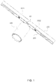
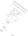
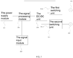
- a dimming track lamp in this embodiment comprises an assembly housing 200 which is in detachable connection with the power supply track100, a control circuit board 300 is in the assembly housing 200 and electrically connected with the power supply track 100, a lamp body 400 arranged on the assembly housing 200, a printed circuit board 500 arranged in the lamp body 400, a light source 600 on the printed circuit board 500 and an optical element 700 arranged in the light output direction of the light source 600, the control circuit board 300 comprises : a power supply module 301 which is electrically connected with the power supply track 100, a signal input module 302, a signal processing module 303 for analyzing and calculating the input signal and generating the control signal, and a signal output module 304 for outputting the control signal to the printed circuit board 500; the light source 600 comprises a warm light source 601 and a cold light source 602, the control signal is used to control the light output of the warm light source 601 and the cold light source 602.
- the dimming track lamp in this embodiment is provided with a light source 600 composed of a warm light source 601 and a cold light source 602.
- a light source 600 composed of a warm light source 601 and a cold light source 602.
- the control circuit board300 is integrated into the assembly housing200 which is in detachable connection with the power supply track100, so that the heat generated by the control circuit board300 controlling the dimming can be dissipated fast through the power supply track100, so that the volume of the track and the assembly housing can be manufactured smaller, the dimming track lamp has high power and can be used in small track.
- the warm light source 601 adopts two warm LED chips
- the cold light source 602 adopts two cold LED chips
- the warm LED chips and the cold LED chips are arranged diagonally to make the light output more uniform.
- the matching mode and structure of the assembly housing 200 and the power supply track100 are the prior art, and there can be multiple matching modes, mainly the matching of the conductive contact on the assembly housing 200 and the conductive strip on the power supply track100, so that the assembly housing 200 can maintain the electrical connection when it slides in the power supply track100.
- the power supply track100 in this embodiment comprises a track body 101which is U-shaped and conductive strip102 arranged at the bottom of the track body 101, the assembly housing 200 comprises at least two conductive contacts 205 electrically connected with the control circuit board 300.
- the conductive contact 205 and the conductive strip102 are butted to realize electrical connection.
- the signal input module 302 mainly receives the data of the brightness and color temperature to be adjusted, which can be realized by remote control or direct adjustment of the mechanical structure.
- the signal input module 302 comprises a brightness adjusting knob 3021 and a color temperature adjusting knob 3022 arranged on the assembly housing 200.
- the assembly housing 200 is a thin strip, which can move in the power supply track100 along the length direction, the brightness adjusting knob 3021 and the color temperature adjusting knob 3022 are arranged at both ends of the assembly housing 200, and the lamp body 400 is arranged in the middle of the assembly housing 200.
- the signal output module 304 comprises a DC-DC unit 3041 that connected with the signal processing module 303, a first switching unit 3042 connected with the DC-DC unit 3041 for controlling the light output of the warm light source 601, and a second switching unit 3043 connected with the DC-DC unit 3041 for controlling the light output of the cold light source602, the first switching unit 3042 and the second switching unit 3043 are also connected with the signal processing module 303.
- Two switching units are led out from the same DC-DC unit 3041, compared with one DC-DC unit corresponding to one switch unit in the prior art, the circuit is simplified.
- the first switching unit 3042 comprises a first resistor R1, a second resistor R2, a first NPN type triode Q1 and a first PMOS transistorQ2, wherein the first resistor R1 and the second resistor R2 are in series, the other end of the first resistor R1 is connected with the positive output terminal of DC-DC unit 3041, the other end of the second resistor R2 is connected with the collector of the first NPN type triode Q1; the emitter of the first NPN type triode Q1 is grounded, the base is connected with the signal processing module 303; the gate of the first PMOS transistorQ2 is connected on the connection line between the first resistor R1 and the second resistor R2, the source is connected with the positive output terminal of the DC-DC unit 3041, the drain is connected with the positive pole of the warm light source 601, and the negative pole of the warm light source 601 is connected with the negative output terminal of the DC-DC unit 3041.
- the second switching unit 3043 comprises a third resistor R3, a four resistor R4, a five resistor R5, a second NPN type triode Q3 and a second PMOS transistor Q4, wherein the third resistor R3, and the four resistor R4 are connected in series, the other end of third resistor R3 is connected with the positive output terminal of DC-DC unit 3041, and the other end of four resistor R4 is connected with the collector of the second NPN type triode Q3; the emitter of the second NPN type triodeQ3 is grounded, the base is connected with the signal processing module 303; the gate of the second PMOS transistor Q4 is connected on the connection line between the third resistor R3 and the four resistor R4, the source is connected with the positive output terminal of the DC-DC unit 3041, the drain is connected with the positive terminal of the cold light source 602; the negative terminal of the cold light source 602 is connected with the negative output terminal of the DC-DC unit 3041; one end of the five resistor R5 is connected with the positive
- the lamp body 400 comprises: a shell 401 is provided with a light outlet 402; a rotary seat 403 is fixed in the shell 401, and the printed circuit board 500 is arranged on one side of the rotary seat 403 which toward the light outlet 402; a rotary connecting rod 404, one end is connected with the rotary seat 403 so that the lamp body 400 can rotate vertically around the connecting part, and the other end is connected with the assembly housing 200 so that the lamp body 400 can rotate horizontally around the connecting part.
- the light outlet 402 is provided with a sealed lamp cover 800 and an outer cover 900.
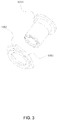
- one end of the rotary connecting rod 404 connected with the rotary seat 403 is a ball head structure 4041, and the rotary seat 403 comprises a first part 4031 and a second part 4032 of a spherical cavity 4033 which can accommodate the rotation of the ball head structure 4041 after splicing.
- the ball head structure 4041 enables the rotary seat 403 to have a larger contact area with the rotating connecting rod 404, so that the heat on the rotary seat 403 can not only diverge through itself and the shell 401, but also be transmitted to the rotary connecting rod 404, the assembly housing 200 and the power supply track 100, so as to improve the heat dissipation effect.
- the first part 4031 and the second part 4032 are connected by bolts 3033.
- the interior of the spherical cavity 4033 has an elastic member 406 butted between the ball head structure 4041 and the spherical cavity 4033.
- the elastic member 406 can provide the support force for the positioning of the lamp body 400.
- the elastic member 406 is a sealing ring, the plane where the sealing ring is located is perpendicular to the central line of the rotating shaft of the rotary seat 403, and the central line of the rotating shaft passes through the center of the sealing ring.
- the assembly housing 200 is a thin strip, comprising a base plate 201, a left plate 202, a right plate 203 and a top plate 204 extending along the length direction, and the top plate 204 is provided with a mounting hole which is rotationally matched with the end of the rotary connecting rod 404.
- the assembly housing 200 comprises a rotation limiting member 408 preventing the excessive rotation of the rotary connecting rod 404. It can effectively avoid the winding of internal wires.
- the rotation limiting member 408 is a limiting gasket located at the inner side of the base plate 201
- the rotary connecting rod 404 is provided with a first limiting protrusion 4044
- the limiting gasket is provided with a second limiting protrusion 4081 to resist the first limiting protrusion 4044 to prevent the rotary connecting rod 404 from excessively rotating.
- the rotary connecting rod 404 includes a threaded main body part 4042 and a fastening part 4043
- the first limiting protrusion 4044 is arranged on the fastening part 4043
- the limit gasket is fixed between the fastening part 4043 and the top plate 204 through the threaded connection of the main body part 4042 and the fastening part 4043.
- the outer edge of the limiting gasket extends along the length direction of the assembly housing 200 to form a third limiting protrusion 4082, and the two sides of the third limiting protrusion 4082 are respectively butted with the inner sides of the left plate 202 and the right plate 203, so that the limiting gasket can rotate finitely.
- the third limiting protrusion 4082 is arranged on both sides of the limit gasket, and the width of the third limiting protrusion 4082 is gradually reduced along the extension direction. This is because in order to improve the heat dissipation effect, the size of the rotary connecting rod404 and the limit gasket are set as large as possible. In order to ensure a certain turning margin, the width of the third limiting protrusion 4082 is gradually reduced along the extension direction, so that the limit gasket is in the shape of a shuttle.
- the first limiting protrusion 4044 at the limit position is first butted with the second limiting protrusion 4081, and then the rotary connecting rod 404 and the limit gasket are turned together to continue to rotate until the third limiting protrusion 4082 is butted with the left plate 202 or the right plate 203, so as to realize 360 ° rotation and avoid blind area in rotation.
Landscapes
- Engineering & Computer Science (AREA)
- General Engineering & Computer Science (AREA)
- Microelectronics & Electronic Packaging (AREA)
- Power Engineering (AREA)
- Arrangement Of Elements, Cooling, Sealing, Or The Like Of Lighting Devices (AREA)
Applications Claiming Priority (1)
| Application Number | Priority Date | Filing Date | Title |
|---|---|---|---|
| CN202010119573.1A CN111288368A (zh) | 2020-02-26 | 2020-02-26 | 一种调光轨道灯 |
Publications (2)
| Publication Number | Publication Date |
|---|---|
| EP3873178A1 true EP3873178A1 (fr) | 2021-09-01 |
| EP3873178B1 EP3873178B1 (fr) | 2023-05-17 |
Family
ID=69960378
Family Applications (1)
| Application Number | Title | Priority Date | Filing Date |
|---|---|---|---|
| EP20165171.8A Active EP3873178B1 (fr) | 2020-02-26 | 2020-03-24 | Lampe de rail à gradation |
Country Status (3)
| Country | Link |
|---|---|
| US (1) | US11221129B2 (fr) |
| EP (1) | EP3873178B1 (fr) |
| CN (1) | CN111288368A (fr) |
Families Citing this family (3)
| Publication number | Priority date | Publication date | Assignee | Title |
|---|---|---|---|---|
| USD962530S1 (en) * | 2020-05-08 | 2022-08-30 | Vibia Lighting, S.L.U. | Lighting fixture |
| USD962529S1 (en) * | 2020-05-08 | 2022-08-30 | Vibia Lighting, S.L.U. | Lighting fixture |
| CN115151002B (zh) * | 2022-05-20 | 2025-06-24 | 欧普照明股份有限公司 | 照明系统控制器、轨道和照明系统 |
Citations (3)
| Publication number | Priority date | Publication date | Assignee | Title |
|---|---|---|---|---|
| DE102012101327A1 (de) * | 2011-02-25 | 2012-08-30 | Andreas Hierzer | Lichtschienensystem |
| US20120287671A1 (en) * | 2011-05-13 | 2012-11-15 | Rambus Inc. | Lighting assembly |
| WO2017106598A1 (fr) * | 2015-12-16 | 2017-06-22 | Black Tank, Llc | Système d'éclairage et procédé de commande de courant réglable par modulation d'impulsions en durée (pwm) |
Family Cites Families (17)
| Publication number | Priority date | Publication date | Assignee | Title |
|---|---|---|---|---|
| US6135615A (en) * | 1999-04-28 | 2000-10-24 | Lee; Cheng-Ping | Lamp suspension track assembly |
| WO2005089293A2 (fr) * | 2004-03-15 | 2005-09-29 | Color Kinetics Incorporated | Procédés et systèmes pour la fourniture de systèmes d'éclairage |
| US8890435B2 (en) * | 2011-03-11 | 2014-11-18 | Ilumi Solutions, Inc. | Wireless lighting control system |
| CN203036412U (zh) * | 2013-01-09 | 2013-07-03 | 佛山市楚光照明电器有限公司 | 一种led轨道射灯 |
| CN203395750U (zh) * | 2013-08-26 | 2014-01-15 | 深圳市众明半导体照明有限公司 | 轨道灯 |
| CN104684219B (zh) * | 2015-03-09 | 2017-05-10 | 北京幻腾科技有限公司 | 一种led照明设备和驱动电路 |
| CN105025635B (zh) * | 2015-07-31 | 2018-04-03 | 浙江嘉乐智能技术有限公司 | 一种led调光调色温电路 |
| CN107152616A (zh) * | 2017-07-11 | 2017-09-12 | 上海顿格电子贸易有限公司 | 一种可调光调色温的智能led球泡灯 |
| CN207283871U (zh) * | 2017-09-06 | 2018-04-27 | 成都星达微科技有限公司 | 一种基于光控开关和红外感应的智能照明型路由器 |
| CN207471279U (zh) * | 2017-10-20 | 2018-06-08 | 中山市智观照明科技有限公司 | 一种具备调光功能的轨道头 |
| CN207990354U (zh) * | 2018-03-16 | 2018-10-19 | 赛尔富电子有限公司 | 一种led导轨射灯 |
| CN208817201U (zh) * | 2018-08-31 | 2019-05-03 | 吴志华 | 一种新型的led轨道灯 |
| CN208634906U (zh) * | 2018-09-20 | 2019-03-22 | 江门市丰泽灯饰有限公司 | 一种低压调光调色温轨道射灯 |
| CN208846216U (zh) * | 2018-11-05 | 2019-05-10 | 深圳市金卡罗智能照明科技有限公司 | 可调光导轨射灯 |
| CN209311845U (zh) * | 2019-01-28 | 2019-08-27 | 深圳市元科摄影器材有限公司 | 一种卷布灯 |
| CN110425502A (zh) * | 2019-07-22 | 2019-11-08 | 赛尔富电子有限公司 | 一种供电的轨道系统以及与该轨道系统配合安装的灯具 |
| CN212252212U (zh) * | 2020-02-26 | 2020-12-29 | 赛尔富电子有限公司 | 一种调光轨道灯 |
-
2020
- 2020-02-26 CN CN202010119573.1A patent/CN111288368A/zh active Pending
- 2020-03-24 EP EP20165171.8A patent/EP3873178B1/fr active Active
- 2020-03-30 US US16/835,135 patent/US11221129B2/en active Active
Patent Citations (3)
| Publication number | Priority date | Publication date | Assignee | Title |
|---|---|---|---|---|
| DE102012101327A1 (de) * | 2011-02-25 | 2012-08-30 | Andreas Hierzer | Lichtschienensystem |
| US20120287671A1 (en) * | 2011-05-13 | 2012-11-15 | Rambus Inc. | Lighting assembly |
| WO2017106598A1 (fr) * | 2015-12-16 | 2017-06-22 | Black Tank, Llc | Système d'éclairage et procédé de commande de courant réglable par modulation d'impulsions en durée (pwm) |
Also Published As
| Publication number | Publication date |
|---|---|
| EP3873178B1 (fr) | 2023-05-17 |
| CN111288368A (zh) | 2020-06-16 |
| US20210262646A1 (en) | 2021-08-26 |
| US11221129B2 (en) | 2022-01-11 |
Similar Documents
| Publication | Publication Date | Title |
|---|---|---|
| US11221129B2 (en) | Dimming track lamp | |
| EP3732391A1 (fr) | Lampe à del | |
| CN212252212U (zh) | 一种调光轨道灯 | |
| CN217875488U (zh) | 一种led灯具 | |
| CN222616835U (zh) | 具备多规格功率及色温集成式调节面板的照明结构 | |
| CN209801423U (zh) | 一种灯具的太阳花式通风散热结构 | |
| CN209213798U (zh) | 一种可防水快速散热矩阵照明灯 | |
| CN220471529U (zh) | 一种用于灯具的智能控制装置及智能灯具 | |
| CN108870135B (zh) | 一种照明设备 | |
| US12467608B1 (en) | LED lamp | |
| CN223564037U (zh) | 一种可调功率色温led灯管 | |
| CN217441551U (zh) | 筒灯及灯光系统 | |
| CN220523925U (zh) | 一种色温可变的智能照明装置 | |
| CN220669233U (zh) | 一种多功能泛光灯 | |
| CN218781160U (zh) | 一种可调灯光的筒射灯 | |
| CN216010451U (zh) | 一种电源内置的色温灯 | |
| CN220471528U (zh) | 一种用于灯具的智能控制装置及智能灯具 | |
| CN220958365U (zh) | 一种拨码可调色温调功率的led灯具 | |
| CN210088513U (zh) | 高光效防触电led灯管 | |
| CN218781210U (zh) | 一种新型led射灯 | |
| CN219912861U (zh) | 一种便于安装的双色温射灯 | |
| CN203517415U (zh) | 一种led照明灯 | |
| CN217082445U (zh) | 一种卡扣式射灯 | |
| CN223399724U (zh) | 一种电源外置灯具及路灯 | |
| CN223909477U (zh) | 喷雾风扇的照明用防水结构以及喷雾风扇 |
Legal Events
| Date | Code | Title | Description |
|---|---|---|---|
| PUAI | Public reference made under article 153(3) epc to a published international application that has entered the european phase |
Free format text: ORIGINAL CODE: 0009012 |
|
| STAA | Information on the status of an ep patent application or granted ep patent |
Free format text: STATUS: THE APPLICATION HAS BEEN PUBLISHED |
|
| AK | Designated contracting states |
Kind code of ref document: A1 Designated state(s): AL AT BE BG CH CY CZ DE DK EE ES FI FR GB GR HR HU IE IS IT LI LT LU LV MC MK MT NL NO PL PT RO RS SE SI SK SM TR |
|
| STAA | Information on the status of an ep patent application or granted ep patent |
Free format text: STATUS: REQUEST FOR EXAMINATION WAS MADE |
|
| 17P | Request for examination filed |
Effective date: 20220203 |
|
| RBV | Designated contracting states (corrected) |
Designated state(s): AL AT BE BG CH CY CZ DE DK EE ES FI FR GB GR HR HU IE IS IT LI LT LU LV MC MK MT NL NO PL PT RO RS SE SI SK SM TR |
|
| GRAP | Despatch of communication of intention to grant a patent |
Free format text: ORIGINAL CODE: EPIDOSNIGR1 |
|
| STAA | Information on the status of an ep patent application or granted ep patent |
Free format text: STATUS: GRANT OF PATENT IS INTENDED |
|
| INTG | Intention to grant announced |
Effective date: 20221202 |
|
| GRAS | Grant fee paid |
Free format text: ORIGINAL CODE: EPIDOSNIGR3 |
|
| GRAA | (expected) grant |
Free format text: ORIGINAL CODE: 0009210 |
|
| STAA | Information on the status of an ep patent application or granted ep patent |
Free format text: STATUS: THE PATENT HAS BEEN GRANTED |
|
| AK | Designated contracting states |
Kind code of ref document: B1 Designated state(s): AL AT BE BG CH CY CZ DE DK EE ES FI FR GB GR HR HU IE IS IT LI LT LU LV MC MK MT NL NO PL PT RO RS SE SI SK SM TR |
|
| REG | Reference to a national code |
Ref country code: GB Ref legal event code: FG4D |
|
| REG | Reference to a national code |
Ref country code: CH Ref legal event code: EP |
|
| REG | Reference to a national code |
Ref country code: DE Ref legal event code: R096 Ref document number: 602020010887 Country of ref document: DE |
|
| REG | Reference to a national code |
Ref country code: IE Ref legal event code: FG4D |
|
| REG | Reference to a national code |
Ref country code: AT Ref legal event code: REF Ref document number: 1568939 Country of ref document: AT Kind code of ref document: T Effective date: 20230615 |
|
| REG | Reference to a national code |
Ref country code: LT Ref legal event code: MG9D |
|
| REG | Reference to a national code |
Ref country code: NL Ref legal event code: MP Effective date: 20230517 |
|
| REG | Reference to a national code |
Ref country code: AT Ref legal event code: MK05 Ref document number: 1568939 Country of ref document: AT Kind code of ref document: T Effective date: 20230517 |
|
| PG25 | Lapsed in a contracting state [announced via postgrant information from national office to epo] |
Ref country code: SE Free format text: LAPSE BECAUSE OF FAILURE TO SUBMIT A TRANSLATION OF THE DESCRIPTION OR TO PAY THE FEE WITHIN THE PRESCRIBED TIME-LIMIT Effective date: 20230517 Ref country code: PT Free format text: LAPSE BECAUSE OF FAILURE TO SUBMIT A TRANSLATION OF THE DESCRIPTION OR TO PAY THE FEE WITHIN THE PRESCRIBED TIME-LIMIT Effective date: 20230918 Ref country code: NO Free format text: LAPSE BECAUSE OF FAILURE TO SUBMIT A TRANSLATION OF THE DESCRIPTION OR TO PAY THE FEE WITHIN THE PRESCRIBED TIME-LIMIT Effective date: 20230817 Ref country code: NL Free format text: LAPSE BECAUSE OF FAILURE TO SUBMIT A TRANSLATION OF THE DESCRIPTION OR TO PAY THE FEE WITHIN THE PRESCRIBED TIME-LIMIT Effective date: 20230517 Ref country code: ES Free format text: LAPSE BECAUSE OF FAILURE TO SUBMIT A TRANSLATION OF THE DESCRIPTION OR TO PAY THE FEE WITHIN THE PRESCRIBED TIME-LIMIT Effective date: 20230517 Ref country code: AT Free format text: LAPSE BECAUSE OF FAILURE TO SUBMIT A TRANSLATION OF THE DESCRIPTION OR TO PAY THE FEE WITHIN THE PRESCRIBED TIME-LIMIT Effective date: 20230517 |
|
| PG25 | Lapsed in a contracting state [announced via postgrant information from national office to epo] |
Ref country code: RS Free format text: LAPSE BECAUSE OF FAILURE TO SUBMIT A TRANSLATION OF THE DESCRIPTION OR TO PAY THE FEE WITHIN THE PRESCRIBED TIME-LIMIT Effective date: 20230517 Ref country code: PL Free format text: LAPSE BECAUSE OF FAILURE TO SUBMIT A TRANSLATION OF THE DESCRIPTION OR TO PAY THE FEE WITHIN THE PRESCRIBED TIME-LIMIT Effective date: 20230517 Ref country code: LV Free format text: LAPSE BECAUSE OF FAILURE TO SUBMIT A TRANSLATION OF THE DESCRIPTION OR TO PAY THE FEE WITHIN THE PRESCRIBED TIME-LIMIT Effective date: 20230517 Ref country code: LT Free format text: LAPSE BECAUSE OF FAILURE TO SUBMIT A TRANSLATION OF THE DESCRIPTION OR TO PAY THE FEE WITHIN THE PRESCRIBED TIME-LIMIT Effective date: 20230517 Ref country code: IS Free format text: LAPSE BECAUSE OF FAILURE TO SUBMIT A TRANSLATION OF THE DESCRIPTION OR TO PAY THE FEE WITHIN THE PRESCRIBED TIME-LIMIT Effective date: 20230917 Ref country code: HR Free format text: LAPSE BECAUSE OF FAILURE TO SUBMIT A TRANSLATION OF THE DESCRIPTION OR TO PAY THE FEE WITHIN THE PRESCRIBED TIME-LIMIT Effective date: 20230517 Ref country code: GR Free format text: LAPSE BECAUSE OF FAILURE TO SUBMIT A TRANSLATION OF THE DESCRIPTION OR TO PAY THE FEE WITHIN THE PRESCRIBED TIME-LIMIT Effective date: 20230818 |
|
| PG25 | Lapsed in a contracting state [announced via postgrant information from national office to epo] |
Ref country code: FI Free format text: LAPSE BECAUSE OF FAILURE TO SUBMIT A TRANSLATION OF THE DESCRIPTION OR TO PAY THE FEE WITHIN THE PRESCRIBED TIME-LIMIT Effective date: 20230517 |
|
| PG25 | Lapsed in a contracting state [announced via postgrant information from national office to epo] |
Ref country code: SK Free format text: LAPSE BECAUSE OF FAILURE TO SUBMIT A TRANSLATION OF THE DESCRIPTION OR TO PAY THE FEE WITHIN THE PRESCRIBED TIME-LIMIT Effective date: 20230517 |
|
| PG25 | Lapsed in a contracting state [announced via postgrant information from national office to epo] |
Ref country code: SM Free format text: LAPSE BECAUSE OF FAILURE TO SUBMIT A TRANSLATION OF THE DESCRIPTION OR TO PAY THE FEE WITHIN THE PRESCRIBED TIME-LIMIT Effective date: 20230517 Ref country code: SK Free format text: LAPSE BECAUSE OF FAILURE TO SUBMIT A TRANSLATION OF THE DESCRIPTION OR TO PAY THE FEE WITHIN THE PRESCRIBED TIME-LIMIT Effective date: 20230517 Ref country code: RO Free format text: LAPSE BECAUSE OF FAILURE TO SUBMIT A TRANSLATION OF THE DESCRIPTION OR TO PAY THE FEE WITHIN THE PRESCRIBED TIME-LIMIT Effective date: 20230517 Ref country code: EE Free format text: LAPSE BECAUSE OF FAILURE TO SUBMIT A TRANSLATION OF THE DESCRIPTION OR TO PAY THE FEE WITHIN THE PRESCRIBED TIME-LIMIT Effective date: 20230517 Ref country code: DK Free format text: LAPSE BECAUSE OF FAILURE TO SUBMIT A TRANSLATION OF THE DESCRIPTION OR TO PAY THE FEE WITHIN THE PRESCRIBED TIME-LIMIT Effective date: 20230517 Ref country code: CZ Free format text: LAPSE BECAUSE OF FAILURE TO SUBMIT A TRANSLATION OF THE DESCRIPTION OR TO PAY THE FEE WITHIN THE PRESCRIBED TIME-LIMIT Effective date: 20230517 |
|
| REG | Reference to a national code |
Ref country code: DE Ref legal event code: R097 Ref document number: 602020010887 Country of ref document: DE |
|
| PLBE | No opposition filed within time limit |
Free format text: ORIGINAL CODE: 0009261 |
|
| STAA | Information on the status of an ep patent application or granted ep patent |
Free format text: STATUS: NO OPPOSITION FILED WITHIN TIME LIMIT |
|
| 26N | No opposition filed |
Effective date: 20240220 |
|
| PG25 | Lapsed in a contracting state [announced via postgrant information from national office to epo] |
Ref country code: SI Free format text: LAPSE BECAUSE OF FAILURE TO SUBMIT A TRANSLATION OF THE DESCRIPTION OR TO PAY THE FEE WITHIN THE PRESCRIBED TIME-LIMIT Effective date: 20230517 |
|
| PG25 | Lapsed in a contracting state [announced via postgrant information from national office to epo] |
Ref country code: SI Free format text: LAPSE BECAUSE OF FAILURE TO SUBMIT A TRANSLATION OF THE DESCRIPTION OR TO PAY THE FEE WITHIN THE PRESCRIBED TIME-LIMIT Effective date: 20230517 Ref country code: IT Free format text: LAPSE BECAUSE OF FAILURE TO SUBMIT A TRANSLATION OF THE DESCRIPTION OR TO PAY THE FEE WITHIN THE PRESCRIBED TIME-LIMIT Effective date: 20230517 |
|
| REG | Reference to a national code |
Ref country code: CH Ref legal event code: PL |
|
| PG25 | Lapsed in a contracting state [announced via postgrant information from national office to epo] |
Ref country code: BG Free format text: LAPSE BECAUSE OF FAILURE TO SUBMIT A TRANSLATION OF THE DESCRIPTION OR TO PAY THE FEE WITHIN THE PRESCRIBED TIME-LIMIT Effective date: 20230517 |
|
| PG25 | Lapsed in a contracting state [announced via postgrant information from national office to epo] |
Ref country code: LU Free format text: LAPSE BECAUSE OF NON-PAYMENT OF DUE FEES Effective date: 20240324 |
|
| PG25 | Lapsed in a contracting state [announced via postgrant information from national office to epo] |
Ref country code: MC Free format text: LAPSE BECAUSE OF FAILURE TO SUBMIT A TRANSLATION OF THE DESCRIPTION OR TO PAY THE FEE WITHIN THE PRESCRIBED TIME-LIMIT Effective date: 20230517 |
|
| GBPC | Gb: european patent ceased through non-payment of renewal fee |
Effective date: 20240324 |
|
| PG25 | Lapsed in a contracting state [announced via postgrant information from national office to epo] |
Ref country code: MC Free format text: LAPSE BECAUSE OF FAILURE TO SUBMIT A TRANSLATION OF THE DESCRIPTION OR TO PAY THE FEE WITHIN THE PRESCRIBED TIME-LIMIT Effective date: 20230517 Ref country code: LU Free format text: LAPSE BECAUSE OF NON-PAYMENT OF DUE FEES Effective date: 20240324 Ref country code: BG Free format text: LAPSE BECAUSE OF FAILURE TO SUBMIT A TRANSLATION OF THE DESCRIPTION OR TO PAY THE FEE WITHIN THE PRESCRIBED TIME-LIMIT Effective date: 20230517 |
|
| REG | Reference to a national code |
Ref country code: BE Ref legal event code: MM Effective date: 20240331 |
|
| PG25 | Lapsed in a contracting state [announced via postgrant information from national office to epo] |
Ref country code: BE Free format text: LAPSE BECAUSE OF NON-PAYMENT OF DUE FEES Effective date: 20240331 |
|
| PG25 | Lapsed in a contracting state [announced via postgrant information from national office to epo] |
Ref country code: GB Free format text: LAPSE BECAUSE OF NON-PAYMENT OF DUE FEES Effective date: 20240324 |
|
| PG25 | Lapsed in a contracting state [announced via postgrant information from national office to epo] |
Ref country code: FR Free format text: LAPSE BECAUSE OF NON-PAYMENT OF DUE FEES Effective date: 20240331 |
|
| PG25 | Lapsed in a contracting state [announced via postgrant information from national office to epo] |
Ref country code: IE Free format text: LAPSE BECAUSE OF NON-PAYMENT OF DUE FEES Effective date: 20240324 |
|
| PG25 | Lapsed in a contracting state [announced via postgrant information from national office to epo] |
Ref country code: IE Free format text: LAPSE BECAUSE OF NON-PAYMENT OF DUE FEES Effective date: 20240324 Ref country code: GB Free format text: LAPSE BECAUSE OF NON-PAYMENT OF DUE FEES Effective date: 20240324 Ref country code: FR Free format text: LAPSE BECAUSE OF NON-PAYMENT OF DUE FEES Effective date: 20240331 Ref country code: BE Free format text: LAPSE BECAUSE OF NON-PAYMENT OF DUE FEES Effective date: 20240331 Ref country code: CH Free format text: LAPSE BECAUSE OF NON-PAYMENT OF DUE FEES Effective date: 20240331 |
|
| PGFP | Annual fee paid to national office [announced via postgrant information from national office to epo] |
Ref country code: DE Payment date: 20250331 Year of fee payment: 6 |
|
| PG25 | Lapsed in a contracting state [announced via postgrant information from national office to epo] |
Ref country code: CY Free format text: LAPSE BECAUSE OF FAILURE TO SUBMIT A TRANSLATION OF THE DESCRIPTION OR TO PAY THE FEE WITHIN THE PRESCRIBED TIME-LIMIT; INVALID AB INITIO Effective date: 20200324 |
|
| PG25 | Lapsed in a contracting state [announced via postgrant information from national office to epo] |
Ref country code: HU Free format text: LAPSE BECAUSE OF FAILURE TO SUBMIT A TRANSLATION OF THE DESCRIPTION OR TO PAY THE FEE WITHIN THE PRESCRIBED TIME-LIMIT; INVALID AB INITIO Effective date: 20200324 |
|
| PG25 | Lapsed in a contracting state [announced via postgrant information from national office to epo] |
Ref country code: TR Free format text: LAPSE BECAUSE OF FAILURE TO SUBMIT A TRANSLATION OF THE DESCRIPTION OR TO PAY THE FEE WITHIN THE PRESCRIBED TIME-LIMIT Effective date: 20230517 |