EP3873200B1 - System und verfahren zur werkzeugpositionierung, drehbare melkplattform und computerprogramm - Google Patents
System und verfahren zur werkzeugpositionierung, drehbare melkplattform und computerprogramm Download PDFInfo
- Publication number
- EP3873200B1 EP3873200B1 EP19802316.0A EP19802316A EP3873200B1 EP 3873200 B1 EP3873200 B1 EP 3873200B1 EP 19802316 A EP19802316 A EP 19802316A EP 3873200 B1 EP3873200 B1 EP 3873200B1
- Authority
- EP
- European Patent Office
- Prior art keywords
- tools
- tool
- image data
- dimensional image
- img3d
- Prior art date
- Legal status (The legal status is an assumption and is not a legal conclusion. Google has not performed a legal analysis and makes no representation as to the accuracy of the status listed.)
- Active
Links
Images

Classifications
-
- A—HUMAN NECESSITIES
- A01—AGRICULTURE; FORESTRY; ANIMAL HUSBANDRY; HUNTING; TRAPPING; FISHING
- A01K—ANIMAL HUSBANDRY; AVICULTURE; APICULTURE; PISCICULTURE; FISHING; REARING OR BREEDING ANIMALS, NOT OTHERWISE PROVIDED FOR; NEW BREEDS OF ANIMALS
- A01K1/00—Housing animals; Equipment therefor
- A01K1/12—Milking stations
- A01K1/126—Carousels
-
- A—HUMAN NECESSITIES
- A01—AGRICULTURE; FORESTRY; ANIMAL HUSBANDRY; HUNTING; TRAPPING; FISHING
- A01J—MANUFACTURE OF DAIRY PRODUCTS
- A01J5/00—Milking machines or devices
- A01J5/017—Automatic attaching or detaching of clusters
-
- A—HUMAN NECESSITIES
- A01—AGRICULTURE; FORESTRY; ANIMAL HUSBANDRY; HUNTING; TRAPPING; FISHING
- A01J—MANUFACTURE OF DAIRY PRODUCTS
- A01J5/00—Milking machines or devices
- A01J5/017—Automatic attaching or detaching of clusters
- A01J5/0175—Attaching of clusters
-
- B—PERFORMING OPERATIONS; TRANSPORTING
- B25—HAND TOOLS; PORTABLE POWER-DRIVEN TOOLS; MANIPULATORS
- B25J—MANIPULATORS; CHAMBERS PROVIDED WITH MANIPULATION DEVICES
- B25J15/00—Gripping heads and other end effectors
- B25J15/0052—Gripping heads and other end effectors multiple gripper units or multiple end effectors
-
- B—PERFORMING OPERATIONS; TRANSPORTING
- B25—HAND TOOLS; PORTABLE POWER-DRIVEN TOOLS; MANIPULATORS
- B25J—MANIPULATORS; CHAMBERS PROVIDED WITH MANIPULATION DEVICES
- B25J15/00—Gripping heads and other end effectors
- B25J15/04—Gripping heads and other end effectors with provision for the remote detachment or exchange of the head or parts thereof
- B25J15/0491—Gripping heads and other end effectors with provision for the remote detachment or exchange of the head or parts thereof comprising end-effector racks
-
- B—PERFORMING OPERATIONS; TRANSPORTING
- B25—HAND TOOLS; PORTABLE POWER-DRIVEN TOOLS; MANIPULATORS
- B25J—MANIPULATORS; CHAMBERS PROVIDED WITH MANIPULATION DEVICES
- B25J9/00—Program-controlled manipulators
- B25J9/16—Program controls
- B25J9/1694—Program controls characterised by use of sensors other than normal servo-feedback from position, speed or acceleration sensors, perception control, multi-sensor controlled systems, sensor fusion
- B25J9/1697—Vision controlled systems
-
- G—PHYSICS
- G06—COMPUTING OR CALCULATING; COUNTING
- G06T—IMAGE DATA PROCESSING OR GENERATION, IN GENERAL
- G06T7/00—Image analysis
- G06T7/70—Determining position or orientation of objects or cameras
- G06T7/73—Determining position or orientation of objects or cameras using feature-based methods
- G06T7/74—Determining position or orientation of objects or cameras using feature-based methods involving reference images or patches
-
- G—PHYSICS
- G05—CONTROLLING; REGULATING
- G05B—CONTROL OR REGULATING SYSTEMS IN GENERAL; FUNCTIONAL ELEMENTS OF SUCH SYSTEMS; MONITORING OR TESTING ARRANGEMENTS FOR SUCH SYSTEMS OR ELEMENTS
- G05B2219/00—Program-control systems
- G05B2219/30—Nc systems
- G05B2219/45—Nc applications
- G05B2219/45113—Animal handling, milking robot
-
- G—PHYSICS
- G06—COMPUTING OR CALCULATING; COUNTING
- G06T—IMAGE DATA PROCESSING OR GENERATION, IN GENERAL
- G06T2207/00—Indexing scheme for image analysis or image enhancement
- G06T2207/10—Image acquisition modality
- G06T2207/10028—Range image; Depth image; 3D point clouds
-
- G—PHYSICS
- G06—COMPUTING OR CALCULATING; COUNTING
- G06T—IMAGE DATA PROCESSING OR GENERATION, IN GENERAL
- G06T2207/00—Indexing scheme for image analysis or image enhancement
- G06T2207/30—Subject of image; Context of image processing
- G06T2207/30108—Industrial image inspection
- G06T2207/30164—Workpiece; Machine component
-
- G—PHYSICS
- G06—COMPUTING OR CALCULATING; COUNTING
- G06T—IMAGE DATA PROCESSING OR GENERATION, IN GENERAL
- G06T2207/00—Indexing scheme for image analysis or image enhancement
- G06T2207/30—Subject of image; Context of image processing
- G06T2207/30242—Counting objects in image
Definitions
- the present invention relates generally to the initializing of an automatic milking equipment before operation. Especially, the invention relates to a system for determining the tool positions in an automatic milking arrangement and a method implemented in such a system. The invention also relates to rotary milking platform, a computer program and a non-volatile data carrier.
- Today's automatic milking arrangements are highly complex installations. This is particularly true for rotary milking platforms, where a relatively large number of milking stations are served by a milking robot, or similar automatic equipment. Inter alia, this means that the milking robot attaches teatcups and other tools, e.g. cleaning cups, to the animals in a fully automatic manner. Therefore, the milking robot must be capable of automatically retrieving relevant tools from a storage place and possibly returning them thereto after completing each stage of the milking procedure. This, in turn, requires that the milking robot has very accurate knowledge about the respective position for each tool.
- an operator teaches the milking robot relevant tool pick-up positions by controlling, for example via a joystick, a grip device of the milking robot to the space coordinate where the grip device shall be positioned when picking up a particular tool.
- the operator programs this position into the control unit for the milking robot by entering a confirming command.
- Such semi manual programming of the tool positions is not ideal, for instance due to various accuracies in the user operated control link for the milking robot, and because - for safety reasons - the operator may need to be located at a place from which it is difficult, or even impossible, to see if the grip device is actually located at the desired pick-up position.
- a rotary milking platform typically has a rather large number of milking stalls, say up to 80, and sometimes even more.
- each milking stall has its own set of tools in the form of teatcups, and perhaps one or more cleaning cups.
- US 2010/278374 A1 discloses an apparatus for recognizing and determining the position of at least one teatcup of at least one teatcup magazine.
- the apparatus emits waves into a region which is expected to contain a teatcup or teatcups.
- the apparatus includes a detector for detecting reflections of the waves.
- the apparatus includes a unit for evaluating the reflections in order to determine if the reflections originate from the teatcup or cups.
- the apparatus includes a unit for determining the position of the teatcup or cups if it is established that the reflections originate from the teatcup.
- US 6 427 625 B1 discloses an apparatus for milking an animal comprising a first set of teatcups and a second set of teatcups, said first set of teatcups comprising at least two teatcups of the same size or shape, said second set of teatcups comprising at least two teatcups of the same size or shape, each said teatcups being elongated and comprising a rigid shell and a flexible liner forming a pulsation space, said liner being adapted to receive a teat at one end and to let out extracted milk at a second end.
- the first set of teatcups comprises teatcups of a first size or shape and the second set of teatcups comprises teatcups of a second size or shape, the first size or shape being different from the second size or shape.
- US 2011/061596 A1 discloses a control unit which controls a gripper of a robotic arm to hold teatcups during removal from teatcup magazine.
- a reference entity has fixed spatial relationship with the teatcups.
- a remote detecting unit receives wireless energy reflected against the reference entity while moving the robotic arm towards the teatcup for removing the teatcup from the magazine.
- the object of the present invention is therefore to offer a convenient solution for determining the respective positions of the tools in an automatic milking arrangement in an efficient and accurate manner.
- the object is achieved by a system according to claim 1.
- the system contains a camera and a control unit.
- the camera is configured to, from an origin location, register three-dimensional image data of at least four tools whose respective positions are to be determined.
- the control unit is configured to cause the camera to obtain three-dimensional image data representing the at least four tools.
- the control unit is configured to identify tool candidates in the three-dimensional image data using an algorithm involving matching the image data against reference data.
- the control unit is configured to calculate a respective position for the at least four tools based on the origin location and data expressing respective distances from the origin location to each of the identified tool candidates.
- the at least four tools are presumed to be stored in a dedicated space and be arranged according to a spatially even distribution relative to one another. Therefore, the control unit is further configured to disregard any tool candidate, which is detected at such a position that the position for the candidate deviates from the spatially even distribution.
- each respective position of all the tools in all milking stations of an automatic milking arrangement can be specifically registered with high accuracy and stored for later use in a fully automatic manner, irrespective of whether the tools are organized along a line, along an arc or in a square.
- control unit is configured to apply a linear regression classification algorithm on the three-dimensional image data to determine the spatially even distribution of the at least four tools.
- each tool occupies a volume extending in all three space dimensions, it is advantageous to define the position for a particular tool to be a particular point on a depicted object in the three-dimensional image data.
- the particular point may be a well-defined point on an identified tool candidate.
- control unit is configured to store the respective positions for the at least four tools in a memory unit.
- the stored respective positions are retrievable from memory unit by a tool-pickup system in connection with picking up at least one of the at least four tools for attachment to an animal.
- the at least four tools are placed in a tool rack and the system includes a grip device which is arranged on a robotic arm.
- the control unit is further configured to retrieve the stored respective positions from the memory unit, and control the robotic arm and the grip device to pick up at least one of the at least four tools from the tool rack.
- the respective position for each tool is expressed in terms of space coordinates for a particular point on an object depicted in the three-dimensional image data.
- the at least four tools are arranged relative to one another in a predefined pattern.
- the control unit is configured to use information about the predefined pattern to confirm and/or disregard at least one of the tool candidates.
- the at least four tools may be arranged along a line.
- the control unit is configured to disregard any tool candidate that is detected at an outlier distance exceeding a second threshold distance from an estimated line interconnecting at least two other tool candidates in a set of tool candidates for said tools.
- the control unit is configured to disregard a tool candidate that is detected at such a position that the tool candidate results in that a difference between first and second inter-distances exceeds a third threshold distance; where the first inter-distance is an interspace between a primary pair of neighboring tool candidates including the tool candidate and a first tool candidate and the second inter-distance is an interspace between a secondary pair of neighboring tool candidates including the tool candidate and a second tool candidate.
- the first inter-distance is an interspace between a primary pair of neighboring tool candidates including the tool candidate and a first tool candidate
- the second inter-distance is an interspace between a secondary pair of neighboring tool candidates including the tool candidate and a second tool candidate.
- the control unit is configured to reposition the camera to a new origin location.
- the control unit is configured to, from the new origin location, cause the camera to obtain updated three-dimensional image data representing the at least four tools.
- the three-dimensional image data may be dynamic. This means that the data may be represented by a video sequence and/or be built up from multiple still images registered from one or more origin locations in one or more angles.
- the control unit is configured to calculate a respective position for the at least four tools based on the new origin location, and data expressing respective distances from the new origin location to each of the identified tool candidates.
- the camera is arranged on the robotic arm.
- this is advantageous because it allows convenient movement and repositioning of the camera.
- the camera that is used during normal operation of the milking arrangement can also be used for programming the tool positions into the system.
- the object is achieved by a rotary milking platform having a plurality of milking stalls.
- Each milking stall includes at least four tools, and the rotary milking platform contains the above-described system for determining the positions of tools.
- this rotary milking platform is advantageous because regardless of the platform size, no coordinate translations are required to register the tool positions.
- the object is achieved by a method according to claim 9.
- the method involves registering via a camera at an origin location, three-dimensional image data representing at least four tools whose positions are to be determined.
- the method further involves identifying tool candidates in the three-dimensional image data using an algorithm involving matching the image data against reference data.
- a respective position for the at least four tools is then calculated based on the origin location and data expressing respective distances from the origin location to each of the identified tool candidates.
- the at least four tools are arranged according to a spatially even distribution relative to one another.
- the method further involves disregarding any tool candidate detected at such a position that the position for the candidate deviates from the spatially even distribution.
- the object is achieved by a computer program loadable into a non-volatile data carrier communicatively connected to a processing unit.
- the computer program includes software for executing the above method when the program is run on the processing unit.
- Figure 1 we see a system according to one embodiment of the invention.
- the system is arranged to determine the respective positions of four different tools, for example a set of teatcups 141, 142, 143 and 144.
- the system includes a camera 130 and a control unit 120.
- the camera 130 is configured to register three-dimensional image data D img3D of the tools 141, 142, 143 and 144 whose respective positions are to be determined.
- the camera 130 is a time-of-flight camera (ToF camera), i.e. a range imaging camera system that resolves distance based on the known speed of light.
- the camera 130 may be any alternative imaging system capable of determining the respective distances to the objects being imaged, for example a 2D camera emitting structured light or a combined light detection and ranging, LIDAR, camera system.
- the three-dimensional image data D img3D may be dynamic. This means that the three-dimensional image data D img3D can be represented by a video sequence and/or be built up from multiple still images registered from one or more origin locations Pc in one or more angles.
- the camera 130 is positioned at an origin location Pc, and may either be arranged on a robotic arm 110, as illustrated in Figure 1 , or be placed on another suitable structure, e.g. a tripod.
- the space coordinates (x C , y C , z C ) of the origin location P C are known with high accuracy.
- the three-dimensional image data D img3D registered by the camera 130 forms a basis for determining the position of any object within a view field VF of the camera 130.
- the space coordinates for the particular point can be calculated based on the origin location P C (x C , y C , z C ) and data d 1 (x 1 , y 1 , z 1 ), e.g. a space vector, expressing a distance in three dimensions from the origin location P C (x C , y C , z C ) to the particular point on a depicted object.
- the particular point can be a well-defined point on a first tool candidate T C1 , such as an intersection between a symmetry center of the teatcup body and the liner's edge to the teatcup body.
- the control unit 120 is configured to cause the camera 130 to obtain three-dimensional image data D img3D representing the tools 141, 142, 143 and 144, and forward the three-dimensional image data D img3D to the control unit 120.
- the control unit 120 is then configured to identify tool candidates T C1 , T C2 , T C3 and T C4 in the three-dimensional image data D img3D using an algorithm involving matching the image data D img3D against reference data.
- the reference data may comprise one or more characteristic patterns of the tool and/or a typical tool outline.
- the control unit 120 is configured to calculate a respective position P T1 , P T2 , P T3 and P T4 for each of the tools 141, 142, 143 and 144 based on the origin location P C (x C , y C , z C ) and data expressing respective distances from the origin location P C (x C , y C , z C ) to each of the identified tool candidates T C1 , T C2 , T C3 and T C4 .
- each of the tools 141, 142, 143 and 144 is stored in a dedicated space, such as at a given position in a rack 150, it can be presumed that the tools 141, 142, 143 and 144 have predefined locations relative to one another. More precisely, the tools 141, 142, 143 and 144 are presumed to be arranged according to a spatially even distribution relative to one another. In Figure 1 , this inter-tool relationship is illustrated by means of an equal distance ⁇ d separating each neighboring tool from one another in the rack 150.
- the control unit 120 is configured to disregard any tool candidate T C2 , which is detected at such a position that the position for the candidate T C2 deviates from the spatially even distribution. To determine whether or not a tool candidate deviates from the spatially even distribution, the control unit 120 may be configured to formulate the pattern recognition problem in the image data D img3D in terms of linear regression.
- control unit 120 is preferably configured to apply a linear regression classification algorithm (LRC) on the three-dimensional image data D img3D to determine any deviation from the spatially even distribution of the 141, 142, 143 and 144.
- LRC linear regression classification algorithm
- the ability to distinguish the evenly distributed tools from other objects in the image data D img3D is beneficial, inter alia because the control unit 120 can thereby avoid regarding a pole, other stalling equipment or similar tool like object, in proximity to the tools as a tool candidate.
- the control unit 120 is configured to disregard any second tool candidate T C2 that is detected at a separation distance d s from a first tool candidate T C1 , if the separation distance d s exceeds a first threshold distance d th1 in relation to the predefined relative locations ⁇ d. For example, if the equal distance ⁇ d is 10 centimeters, any second tool candidate T C2 detected more than 15 centimeters from a first tool candidate T C1 may be discarded. Of course, this strategy is actually applicable to any number of tools larger than two.
- the control unit 120 is preferably configured to use information about the predefined pattern to confirm and/or disregard at least one of the tool candidates T C1 , T C2 , T C3 and T C4 . Below, this will be exemplified by two embodiments of the invention.
- Figure 3 illustrates a situation where a set of tools are stored in a rack 150 according to a linear arrangement.
- the camera 130 has registered three-dimensional image data D img3D in which tool candidates T C1 , T C2 , T C3 and T C4 have been identified.
- a third tool candidate T C3 has been detected at an outlier distance d o from an estimated line L e interconnecting at least two of the other tool candidates, here T C1 , T C2 , and T C4 respectively, in a set of tool candidates for the tools.
- the control unit 120 is configured to disregard the detected tool candidate T C3 according to one embodiment of the invention.
- control unit 120 may draw further conclusions based on the predefined pattern in which the tools are arranged relative to one another.
- Figure 4 illustrates how an identified tool candidate T C2 can be discarded according to a third embodiment the invention.
- the control unit 120 is configured to use the information about the predefined tool pattern to disregard a tool candidate T C2 , which is detected at such a position that said tool candidate T C2 results in that a difference between a first inter-distance ⁇ d 1 and a second inter-distance ⁇ d 2 exceeds a third threshold distance.
- the first inter-distance ⁇ d 1 is an interspace between a primary pair of neighboring tool candidates, say T C1 and T C2 , that includes said tool candidate T C2 and a first other tool candidate T C1 .
- the second inter-distance is an interspace between a secondary pair of neighboring tool candidates; say T C2 and T C3 , which includes said tool candidate T C2 and another second tool candidate T C3 .
- the predefined pattern in which the tools organized may also be used by the control unit 120 to confirm a tool candidate. I.e. if, for example, a second tool candidate is found at the expected distance ⁇ d from a first tool candidate, the position for the second tool candidate can be confirmed.
- the system includes a memory unit 160, e.g. a storage medium in the form of a Flash memory or a Read Only Memory (ROM).
- the control unit 120 is further configured to store the respective positions [P] for the at least two tools 141, 142, 143 and 144 in the memory unit 160.
- the stored respective positions [P] are retrievable from the memory unit 160 by a tool-pickup system in connection with picking up at least one of the at least four tools 141, 142, 143 and 144, typically for attachment to an animal.
- the at least four tools 141, 142, 143 and 144 are placed in a tool rack 150, as illustrated in Figure 1 .
- the system for determining the positions of tools in the automatic milking arrangement further contains a grip device 115, which is arranged on a robotic arm 110.
- the control unit 120 is configured to retrieve the stored respective positions [P] from the memory unit 160, and control the robotic arm 110 and the grip device 115 to pick up at least one of the at least four tools 141, 142, 143 and 144 from the tool rack 150, so that for example this/these tool(s) can be attached to an animal.
- the grip device 115 may contain one or more electro-magnets configured to cooperate with one or more magnetic members on each of the at least four tools 141, 142, 143 and 144. Alternatively, or in addition thereto, the grip device 115 may contain at least one mechanical gripping claw configured to grasp around the tool itself or a part thereof, e.g. a grip bar.
- the camera 130 is arranged on the robotic arm 110. Namely, this highly facilitates implementing the above above-described procedure.
- control unit 120 and the camera 130 are configured to effect the above-described procedure in an automatic manner by executing a computer program 127. Therefore, the control unit 120 may include a memory unit 126, i.e. non-volatile data carrier, storing the computer program 127, which, in turn, contains software for making processing circuitry in the form of at least one processor in the central control unit 120 execute the above-described actions when the computer program 127 is run on the at least one processor.
- memory unit 126 i.e. non-volatile data carrier
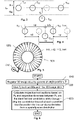
- FIG. 5 shows a rotary milking platform 500 according to one embodiment the invention.
- the rotary milking platform 500 has a plurality of milking stalls 520 i , here 24 altogether. Each of the milking stalls 520 i contains at least four tools, symbolically indicated by the reference numerals 141, 142, 143, 144.
- the rotary milking platform 500 also includes a system for determining the respective tool positions, which is here symbolically indicated via the robotic arm 510. Said positioning system 510 is arranged to calculate a respective position P T1 , P T2 , P T3 and P T4 for the at least four tools 141, 142, 143 and 144 respectively in each of said milking stalls 520 i according to the procedure described above.
- the rotary milking platform 500 is stepwise rotated pass the system 510 for calculating the respective tool positions for all the milking stalls 520 i on the platform 500 in a consecutive manner.
- a first step 610 three-dimensional image data are registered via a camera at a known origin location.
- the three-dimensional image data represent at least four tools of the milking arrangement whose respective positions are to be determined.
- tool candidates are identified in the three-dimensional image data using an algorithm that involves matching the image data against reference data.
- a respective position is calculated for the at least four tools.
- the position calculations are based on the known origin location of the camera and data expressing respective distances from the origin location to each of the identified tool candidates.
- the at least four tools have predefined locations relative to one another. More precisely, the at least four tools are arranged according to a spatially even distribution relative to one another. Any tool candidate disregarded, which is detected at such a position that the position for the candidate deviates from the spatially even distribution.
- All of the process steps, as well as any sub-sequence of steps, described with reference to Figure 6 may be controlled by means of a programmed processor.
- the embodiments of the invention described above with reference to the drawings comprise processor and processes performed in at least one processor, the invention thus also extends to computer programs, particularly computer programs on or in a carrier, adapted for putting the invention into practice.
- the program may be in the form of source code, object code, a code intermediate source and object code such as in partially compiled form, or in any other form suitable for use in the implementation of the process according to the invention.
- the program may either be a part of an operating system, or be a separate application.
- the carrier may be any entity or device capable of carrying the program.
- the carrier may comprise a storage medium, such as a Flash memory, a ROM (Read Only Memory), for example a DVD (Digital Video/Versatile Disk), a CD (Compact Disc) or a semiconductor ROM, an EPROM (Erasable Programmable Read-Only Memory), an EEPROM (Electrically Erasable Programmable Read-Only Memory), or a magnetic recording medium, for example a floppy disc or hard disc.
- the carrier may be a transmissible carrier such as an electrical or optical signal which may be conveyed via electrical or optical cable or by radio or by other means.
- the carrier may be constituted by such cable or device or means.
- the carrier may be an integrated circuit in which the program is embedded, the integrated circuit being adapted for performing, or for use in the performance of, the relevant processes.
Landscapes
- Engineering & Computer Science (AREA)
- Life Sciences & Earth Sciences (AREA)
- Environmental Sciences (AREA)
- Animal Husbandry (AREA)
- Robotics (AREA)
- Mechanical Engineering (AREA)
- Computer Vision & Pattern Recognition (AREA)
- Physics & Mathematics (AREA)
- General Physics & Mathematics (AREA)
- Theoretical Computer Science (AREA)
- Zoology (AREA)
- Biodiversity & Conservation Biology (AREA)
- Length Measuring Devices By Optical Means (AREA)
- Image Processing (AREA)
Claims (15)
- System, um die Positionen von Werkzeugen in einer automatischen Melkanordnung zu bestimmen, das System umfassend:eine Kamera (130), die konfiguriert ist, um, von einem Ursprungsort (Pc) dreidimensionale Bilddaten (Dimg3D) von mindestens vier Werkzeugen (141, 142, 143, 144) zu registrieren, deren jeweilige Positionen bestimmt werden sollen, undeine Steuereinheit (120), die für Folgendes konfiguriert ist:Verursachen, dass die Kamera (130) dreidimensionale Bilddaten (Dimg3D) erhält, die die mindestens vier Werkzeuge darstellen,Identifizieren von Werkzeugkandidaten (TC1, TC2, TC3, TC4) in den dreidimensionalen Bilddaten (Dimg3D) unter Verwendung eines Algorithmus, der ein Abgleichen der dreidimensionalen Bilddaten (Dimg3D) mit Referenzdaten beinhaltet, undBerechnen einer jeweiligen Position (PT1, PT2, PT3, PT4) für die mindestens vier Werkzeuge (141, 142, 143, 144) basierend auf dem Ursprungsort (PC(xC, yC, zC)) und Daten, die jeweilige Abstände (d1(x1, y1, z1)) von dem Ursprungsort zu jedem der identifizierten Werkzeugkandidaten (TC1, TC2, TC3, TC4) ausdrücken,dadurch gekennzeichnet, dassdie Steuereinheit (120) ferner konfiguriert ist, um einen beliebigen Werkzeugkandidaten (TC2) zu ignorieren, der an einer solchen Position erfasst wird, dass die Position für den Kandidaten (TC2) von einer räumlich gleichmäßigen Verteilung abweicht, wodurch die mindestens vier Werkzeuge relativ zueinander angeordnet sind,undwobei, falls eine Verarbeitungszeit nach dem Erhalt der dreidimensionalen Bilddaten (Dimg3D) in der Steuereinheit (120) weniger als eine vordefinierte Anzahl von Werkzeugkandidaten identifiziert wurden, die Steuereinheit (120) konfiguriert ist, um die Kamera (130) an einen neuen Ursprungsort (PC) zu repositionieren, von dem die mindestens vier Werkzeuge (141, 142, 143, 144) in der Kamera (130) sichtbar sind, zu verursachen, dass die Kamera (130) aktualisierte dreidimensionale Bilddaten (Dimg3D) erhält, die die mindestens vier Werkzeuge darstellen, wobei aktualisierte dreidimensionale Bilddaten (Dimg3D) von dem neuen Ursprungsort (PC) registriert wurden, eine jeweilige Position (PT1, PT2, PT3, PT4) für die mindestens vier Werkzeuge (141, 142, 143, 144) basierend auf dem neuen Ursprungsort (Pc) und Daten, die jeweilige Abstände von dem neuen Ursprungsort (PC) zu jedem der identifizierten Werkzeugkandidaten (TC1, TC2, TC3, TC4) ausdrücken, zu berechnen, undwobei die Steuereinheit (120) konfiguriert ist, um die jeweiligen Positionen ([P]) für die mindestens vier Werkzeuge (141, 142, 143, 144) in einer Speichereinheit (160) zu speichern, wobei das System eine Griffvorrichtung (115) umfasst, die auf einem Roboterarm (110) angeordnet ist und nachdem die jeweiligen Positionen ([P]) in der Speichereinheit (160) gespeichert wurden, die Steuereinheit (120) ferner für Folgendes konfiguriert ist:Abrufen der gespeicherten jeweiligen Positionen ([P]) aus der Speichereinheit (160), undSteuern des Roboterarms (110) und der Griffvorrichtung (115), um mindestens eines der mindestens vier Werkzeuge (141, 142, 143, 144) aus dem Werkzeuggestell (150) aufzunehmen.
- System nach Anspruch 1, wobei die Steuereinheit (120) konfiguriert ist, um einen linearen Regressionsklassifikationsalgorithmus auf die dreidimensionalen Bilddaten (Dimg3D) anzuwenden, um die räumlich gleichmäßige Verteilung der mindestens vier Werkzeuge (141, 142, 143, 144) zu bestimmen.
- System nach einem der Ansprüche 1 oder 2, wobei die Steuereinheit (120) konfiguriert ist, um Informationen über ein vordefiniertes Muster zu verwenden, wodurch die Werkzeuge (141, 142, 143, 144) relativ zu einander angeordnet sind, um mindestens einen der Werkzeugkandidaten (TC1, TC2, TC3, TC4) zu bestätigen und/oder zu ignorieren.
- System nach einem der vorstehenden Ansprüche, wobei
die Steuereinheit (120) konfiguriert ist, um einen beliebigen Werkzeugkandidaten (TC3) zu ignorieren, der in einem Sonderfallabstand (do) erfasst wird, der einen zweiten Schwellenwertabstand (dth2) von einer geschätzten Linie (Le) überschreitet, die mindestens zwei andere Werkzeugkandidaten (TC1, TC2, TC4) in einem Satz von Werkzeugkandidaten für die Werkzeuge miteinander verbindet. - System nach Anspruch 4, wobei
die Steuereinheit (120) konfiguriert ist, um einen Werkzeugkandidaten (TC2) zu ignorieren, der an einer solchen Position erfasst wird, dass der Werkzeugkandidat (TC2) dazu führt, dass eine Differenz zwischen einem ersten Zwischenabstand (Δd1) und einem zweiten Zwischenabstand (Δd2) einen dritten Schwellenwertabstand überschreitet, wobei der erste Zwischenabstand (Δd1) ein Zwischenraum zwischen einem primären Paar benachbarter Werkzeugkandidaten (TC1, TC2) ist, einschließlich dem Werkzeugkandidaten (TC2) und einem ersten Werkzeugkandidaten (TC1), und der zweite Zwischenabstand ein Zwischenraum zwischen einem sekundären Paar benachbarter Werkzeugkandidaten einschließlich des Werkzeugkandidaten (TC2) und eines zweiten Werkzeugkandidaten (TC3) ist. - System nach einem der vorstehenden Ansprüche,
wobei die Steuereinheit konfiguriert ist, um die jeweilige Position (PT1, PT2, PT3, PT4) für jedes der mindestens vier Werkzeuge (141, 142, 143, 144) hinsichtlich der Raumkoordinaten für einen speziellen Punkt auf einem Objekt auszudrücken, das in den dreidimensionalen Bilddaten (Dimg3D) geschildert ist. - System nach Anspruch 1, wobei die Kamera (130) konfiguriert ist, um an dem Roboterarm (110) angeordnet zu sein.
- Rotierende Melkplattform (500), die mehrere Melkställe (520i) aufweist, von denen jeder mindestens vier Werkzeuge (141, 142, 143, 144) umfasst, und die rotierende Melkplattform (500) ein System zum Bestimmen der Positionen von Werkzeugen nach einem der vorstehenden Ansprüche umfasst, wobei das System angeordnet ist, um eine jeweilige Position (PT1, PT2, PT3, PT4) für die mindestens vier Werkzeuge (141, 142, 143, 144) in jedem der Melkställe (520i) zu berechnen.
- Verfahren zum Bestimmen der Positionen von Werkzeugen in einer automatischen Melkanordnung, das Verfahren umfassend:Registrieren, über eine Kamera (130) an einem Ursprungsort (PC), dreidimensionaler Bilddaten (Dimg3D), die mindestens vier Werkzeuge (141, 142, 143, 144) darstellen, deren Positionen bestimmt werden sollen,Identifizieren von Werkzeugkandidaten (TC1, TC2, TC3, TC4) in den dreidimensionalen Bilddaten (Dimg3D) unter Verwendung eines Algorithmus, der das Abgleichen der dreidimensionalen Bilddaten (Dimg3D) mit Referenzdaten beinhaltet, undBerechnen einer jeweiligen Position (PT1, PT2, PT3, PT4) für die mindestens vier Werkzeuge (141, 142, 143, 144) basierend auf dem Ursprungsort (Pc(xc, yc, zc)) und Daten, die jeweilige Abstände (d1(x1, y1, z1)) von dem Ursprungsort zu jedem der identifizierten Werkzeugkandidaten (TC1, TC2, TC3, TC4) ausdrücken, gekennzeichnet dadurch, dassdie mindestens vier Werkzeuge (141, 142, 143, 144) gemäß einer räumlich gleichmäßigen Verteilung relativ zueinander angeordnet sind, und das Verfahren umfasst:
Ignorieren eines beliebigen Werkzeugkandidaten (TC2), der an einer solchen Position erfasst wurde, dass die Position für den Kandidaten (TC2) von der räumlich gleichmäßigen Verteilung abweicht, wobei, falls eine Verarbeitungszeit nach dem Erhalt der dreidimensionalen Bilddaten (Dimg3D), weniger als eine vordefinierte Anzahl von Werkzeugkandidaten identifiziert wurden, das Verfahren umfasst:Repositionieren der Kamera (130) an einem neuen Ursprungsort (PC), von dem aus die mindestens vier Werkzeuge (141, 142, 143, 144) in der Kamera (130) sichtbar sind,Verursachen, dass die Kamera (130) aktualisierte dreidimensionale Bilddaten (Dimg3D) erhält, die die mindestens vier Werkzeuge darstellen, wobei aktualisierte dreidimensionale Bilddaten (Dimg3D) von dem neuen Ursprungsort (PC) registriert wurden, undBerechnen einer jeweiligen Position (PT1, PT2, PT3, PT4) für die mindestens vier Werkzeuge (141, 142, 143, 144) basierend auf dem neuen Ursprungsort (Pc) und Daten, die jeweilige Abstände von dem neuen Ursprungsort (Pc) zu jedem der identifizierten Werkzeugkandidaten (TC1, TC2, TC3, TC4) ausdrücken, undSpeichern der jeweiligen Positionen ([P]) für die mindestens vier Werkzeuge (141, 142, 143, 144) in einer Speichereinheit (160), aus der die gespeicherten jeweiligen Positionen ([P]) durch ein Werkzeugaufnahmesystem in Verbindung mit dem Aufnehmen mindestens eines der mindestens vier Werkzeuge (141, 142, 143, 144) für eine Befestigung an einem Tier abrufbar sind, wobei die mindestens vier Werkzeuge (141, 142, 143, 144) in einem Werkzeuggestell (150) platziert sind, wobei das Werkzeugaufnahmesystem eine Griffvorrichtung (115) umfasst, die an einem Roboterarm (110) angeordnet ist, und nachdem die jeweiligen Positionen ([P]) in der Speichereinheit (160) gespeichert wurden, das Verfahren ferner umfasst:Abrufen der gespeicherten jeweiligen Positionen ([P]) aus der Speichereinheit (160), undSteuern des Roboterarms (110) und der Griffvorrichtung (115), um mindestens eines der mindestens vier Werkzeuge (141, 142, 143, 144) aus dem Werkzeuggestell (150) aufzunehmen. - Verfahren nach Anspruch 9, umfassend:Anwenden eines linearen Regressionsklassifikationsalgorithmus auf die dreidimensionalen Bilddaten (Dimg3D), um die räumlich gleichmäßige Verteilung der mindestens vier Werkzeuge (141, 142, 143, 144) zu bestimmen.
- Verfahren nach Anspruch 10, wobei die mindestens vier Werkzeuge (141, 142, 143, 144) in einem vordefinierten Muster relativ zueinander angeordnet sind und das Verfahren umfasst:
Verwenden von Informationen über das vordefinierte Muster, um mindestens einen der Werkzeugkandidaten (TC1, TC2, TC3, TC4) zu bestätigen und/oder zu ignorieren. - Verfahren nach einem der Ansprüche 9 bis 11, wobei die mindestens vier Werkzeuge (141, 142, 143, 144) entlang einer Linie (L) angeordnet sind und das Verfahren umfasst:
Ignorieren eines beliebigen Werkzeugkandidaten (TC3), der in einem Sonderfallabstand (do) erfasst wird, der einen zweiten Schwellenabstand (dth2) von einer geschätzten Linie (Le) überschreitet, der mindestens zwei andere Werkzeugkandidaten (TC1, TC2, TC4) in einem Satz von Werkzeugkandidaten für diese Werkzeuge miteinander verbindet. - Verfahren nach Anspruch 12, wobei die vier Werkzeuge (141, 142, 143, 144) mit einem gleichen Abstand (Δd) zwischen jedem benachbarten Werkzeug der Werkzeuge in der Linie (L) angeordnet sind und das Verfahren umfasst:
Ignorieren eines Werkzeugkandidaten (TC2), der an einer solchen Position erfasst wird, dass der Werkzeugkandidat (TC2) dazu führt, dass eine Differenz zwischen einem ersten Zwischenabstand (Δd1) und einem zweiten Zwischenabstand (Δd2) einen dritten Schwellenwertabstand überschreitet, wobei der erste Zwischenabstand (Δd1) ein Zwischenraum zwischen einem primären Paar benachbarter Werkzeugkandidaten (TC1, TC2) ist, einschließlich dem Werkzeugkandidaten (TC2) und einem ersten Werkzeugkandidaten (TC1), und der zweite Zwischenabstand ein Zwischenraum zwischen einem sekundären Paar benachbarter Werkzeugkandidaten einschließlich des Werkzeugkandidaten (TC2) und eines zweiten Werkzeugkandidaten (TC3) ist. - Verfahren nach einem der Ansprüche 9 bis 13, wobei die jeweilige Position (PT1, PT2, PT3, PT4) für jedes der mindestens vier Werkzeuge (141, 142, 143, 144) hinsichtlich der Raumkoordinaten für einen speziellen Punkt auf einem Objekt ausgedrückt ist, das in den dreidimensionalen Bilddaten (Dimg3D) geschildert ist.
- Computerprogramm (127), das in einen nichtflüchtigen Datenträger (126) ladbar ist, der mit einer Verarbeitungseinheit (125) kommunikativ verbunden ist, wobei das Computerprogramm (127) Software zum Ausführen des Verfahrens nach einem der Ansprüche 9 bis 14 umfasst, wenn das Computerprogramm auf der Verarbeitungseinheit (125) abläuft.
Applications Claiming Priority (2)
| Application Number | Priority Date | Filing Date | Title |
|---|---|---|---|
| SE1800212 | 2018-11-01 | ||
| PCT/SE2019/051070 WO2020091668A1 (en) | 2018-11-01 | 2019-10-28 | Tool-positioning system and method, rotary milking platform, computer program and non-volatile data carrier |
Publications (2)
| Publication Number | Publication Date |
|---|---|
| EP3873200A1 EP3873200A1 (de) | 2021-09-08 |
| EP3873200B1 true EP3873200B1 (de) | 2022-11-09 |
Family
ID=68542721
Family Applications (1)
| Application Number | Title | Priority Date | Filing Date |
|---|---|---|---|
| EP19802316.0A Active EP3873200B1 (de) | 2018-11-01 | 2019-10-28 | System und verfahren zur werkzeugpositionierung, drehbare melkplattform und computerprogramm |
Country Status (5)
| Country | Link |
|---|---|
| US (1) | US11882812B2 (de) |
| EP (1) | EP3873200B1 (de) |
| CN (1) | CN112955003B (de) |
| CA (1) | CA3118049A1 (de) |
| WO (1) | WO2020091668A1 (de) |
Families Citing this family (2)
| Publication number | Priority date | Publication date | Assignee | Title |
|---|---|---|---|---|
| WO2020231314A1 (en) * | 2019-05-14 | 2020-11-19 | Delaval Holding Ab | System and method for measuring key features of a rotary milking parlor arrangement, computer program and non-volatile data carrier |
| US11882819B2 (en) * | 2020-09-30 | 2024-01-30 | Keith Parnas | Fishing rod holder for wash-down of rods and reels |
Family Cites Families (20)
| Publication number | Priority date | Publication date | Assignee | Title |
|---|---|---|---|---|
| DE3742867C3 (de) | 1987-12-17 | 1998-04-09 | Fraunhofer Ges Forschung | Vorrichtung zum Fügen von Elementen in entsprechende Aufnahmeelemente eines Objekts |
| AU6862198A (en) | 1997-04-04 | 1998-10-30 | Alfa Laval Agri Ab | Method and apparatus for generating image information when carrying out animal related operations |
| SE9802614D0 (sv) | 1998-07-24 | 1998-07-24 | Alfa Laval Agri Ab | An apparatus for milking an animal |
| NL1015559C2 (nl) | 2000-06-28 | 2002-01-02 | Idento Electronics Bv | Melksysteem met driedimensionale beeldvorming. |
| NL1032063C2 (nl) * | 2006-06-27 | 2008-01-02 | Maasland Nv | Combinatie van een melkbeker en een flexibele melkslang, koppelstuk, alsmede werkwijze voor het bewaken van integriteit van flexibele melkslang. |
| SE530339C2 (sv) * | 2006-07-13 | 2008-05-06 | Delaval Holding Ab | En apparat och förfarande för att igenkänna och bestämma en position |
| NL1032435C2 (nl) | 2006-09-05 | 2008-03-06 | Maasland Nv | Inrichting voor het automatisch melken van een melkdier. |
| WO2009120129A1 (en) | 2008-03-27 | 2009-10-01 | Delaval Holding Ab | Positioning of teat cups |
| AU2014238531B2 (en) | 2013-02-06 | 2016-12-15 | Delaval Holding Ab | Teat treatment method and apparatus |
| NL2010406C2 (nl) | 2013-03-07 | 2014-09-10 | Rotec Engineering B V | Grijper voor het aanbrengen van melkbekers bij een te melken dier, robotarm en melkmachine voorzien daarvan, en werkwijze daarvoor. |
| GB2546107A (en) * | 2016-01-11 | 2017-07-12 | Rolls Royce Plc | Methods and apparatus for enabling determination of a position of an object |
| NL2016721B1 (nl) | 2016-05-03 | 2017-11-10 | Lely Patent Nv | Werkwijze voor uitvoeren van een speengerelateerde handeling, en robotinrichting daarvoor |
| IL246617B2 (en) | 2016-07-05 | 2023-10-01 | Eyal Brayer | Means and Methods for Free Dome Range |
| DE102016112596A1 (de) | 2016-07-08 | 2018-01-11 | Gea Farm Technologies Gmbh | Verfahren und Vorrichtung zum automatischen Ansetzen von Melkbechern an Zitzen eines milchgebenden Tieres |
| US10558855B2 (en) * | 2016-08-17 | 2020-02-11 | Technologies Holdings Corp. | Vision system with teat detection |
| US9807971B1 (en) * | 2016-08-17 | 2017-11-07 | Technologies Holdings Corp. | Vision system with automatic teat detection |
| US10817970B2 (en) * | 2016-08-17 | 2020-10-27 | Technologies Holdings Corp. | Vision system with teat detection |
| DE102016118620B4 (de) * | 2016-09-30 | 2024-10-02 | Carl Zeiss Industrielle Messtechnik Gmbh | Messsystem und Messverfahren |
| CN106886995B (zh) * | 2017-01-13 | 2019-09-20 | 北京航空航天大学 | 多线性示例回归器聚合的图像显著对象分割方法 |
| CN107950402B (zh) * | 2017-11-29 | 2020-10-30 | 北京伟景智能科技有限公司 | 基于双目视觉的挤奶器自动控制方法 |
-
2019
- 2019-10-28 CN CN201980071646.XA patent/CN112955003B/zh active Active
- 2019-10-28 EP EP19802316.0A patent/EP3873200B1/de active Active
- 2019-10-28 WO PCT/SE2019/051070 patent/WO2020091668A1/en not_active Ceased
- 2019-10-28 CA CA3118049A patent/CA3118049A1/en active Pending
- 2019-10-28 US US17/290,712 patent/US11882812B2/en active Active
Also Published As
| Publication number | Publication date |
|---|---|
| CN112955003A (zh) | 2021-06-11 |
| US11882812B2 (en) | 2024-01-30 |
| WO2020091668A1 (en) | 2020-05-07 |
| CA3118049A1 (en) | 2020-05-07 |
| EP3873200A1 (de) | 2021-09-08 |
| CN112955003B (zh) | 2023-04-07 |
| US20210392841A1 (en) | 2021-12-23 |
Similar Documents
| Publication | Publication Date | Title |
|---|---|---|
| US8281746B2 (en) | Positioning of teat cups | |
| CN110640730B (zh) | 生成用于机器人场景的三维模型的方法和系统 | |
| US20180050451A1 (en) | Picking system and method for controlling picking robot | |
| US20110226183A1 (en) | Handling of teat cups | |
| EP3873200B1 (de) | System und verfahren zur werkzeugpositionierung, drehbare melkplattform und computerprogramm | |
| EP2651211B1 (de) | Verfahren und vorrichtung zum anschliessen von melkbechern an milchtiere | |
| EP3873198B1 (de) | System und verfahren zur werkzeugpositionierung, drehbare melkplattform, computerprogramm und nichtflüchtiger datenträger | |
| JP7844771B2 (ja) | オブジェクトのカメラ画像からオブジェクトの場所を位置特定するための装置及び方法 | |
| CA2972543C (en) | System and method for preparation cup attachment | |
| CN113825395B (zh) | 用于测量旋转挤奶厅布置的关键特征的系统和方法、计算机程序以及非易失性数据载体 | |
| EP3968761B1 (de) | System und verfahren zur bereitstellung einer entscheidungsgrundlage zur steuerung eines roboterarms | |
| CN113232022B (zh) | 一种圆盘传送跟踪控制方法、系统、装置及存储介质 | |
| US20220215502A1 (en) | System and method for providing a decision basis for controlling a robotic arm, computer program and nonvolatile data carrier | |
| US20230210081A1 (en) | System and computer-implemented method for determining an offset for a milking tool in an automatic milking machine, computer program and non-volatile data carrier | |
| EP3873199A1 (de) | Werkzeugaufnahmesystem, verfahren, computerprogramm und nichtflüchtiger datenträger | |
| CN119924742A (zh) | 物品抓取方法、装置及自移动清洁设备 |
Legal Events
| Date | Code | Title | Description |
|---|---|---|---|
| STAA | Information on the status of an ep patent application or granted ep patent |
Free format text: STATUS: UNKNOWN |
|
| STAA | Information on the status of an ep patent application or granted ep patent |
Free format text: STATUS: THE INTERNATIONAL PUBLICATION HAS BEEN MADE |
|
| PUAI | Public reference made under article 153(3) epc to a published international application that has entered the european phase |
Free format text: ORIGINAL CODE: 0009012 |
|
| STAA | Information on the status of an ep patent application or granted ep patent |
Free format text: STATUS: REQUEST FOR EXAMINATION WAS MADE |
|
| 17P | Request for examination filed |
Effective date: 20210517 |
|
| AK | Designated contracting states |
Kind code of ref document: A1 Designated state(s): AL AT BE BG CH CY CZ DE DK EE ES FI FR GB GR HR HU IE IS IT LI LT LU LV MC MK MT NL NO PL PT RO RS SE SI SK SM TR |
|
| DAV | Request for validation of the european patent (deleted) | ||
| DAX | Request for extension of the european patent (deleted) | ||
| GRAP | Despatch of communication of intention to grant a patent |
Free format text: ORIGINAL CODE: EPIDOSNIGR1 |
|
| STAA | Information on the status of an ep patent application or granted ep patent |
Free format text: STATUS: GRANT OF PATENT IS INTENDED |
|
| INTG | Intention to grant announced |
Effective date: 20220527 |
|
| GRAS | Grant fee paid |
Free format text: ORIGINAL CODE: EPIDOSNIGR3 |
|
| GRAA | (expected) grant |
Free format text: ORIGINAL CODE: 0009210 |
|
| STAA | Information on the status of an ep patent application or granted ep patent |
Free format text: STATUS: THE PATENT HAS BEEN GRANTED |
|
| AK | Designated contracting states |
Kind code of ref document: B1 Designated state(s): AL AT BE BG CH CY CZ DE DK EE ES FI FR GB GR HR HU IE IS IT LI LT LU LV MC MK MT NL NO PL PT RO RS SE SI SK SM TR |
|
| REG | Reference to a national code |
Ref country code: GB Ref legal event code: FG4D |
|
| REG | Reference to a national code |
Ref country code: CH Ref legal event code: EP Ref country code: AT Ref legal event code: REF Ref document number: 1529755 Country of ref document: AT Kind code of ref document: T Effective date: 20221115 |
|
| REG | Reference to a national code |
Ref country code: DE Ref legal event code: R096 Ref document number: 602019021804 Country of ref document: DE |
|
| REG | Reference to a national code |
Ref country code: IE Ref legal event code: FG4D |
|
| REG | Reference to a national code |
Ref country code: NL Ref legal event code: FP |
|
| REG | Reference to a national code |
Ref country code: LT Ref legal event code: MG9D |
|
| REG | Reference to a national code |
Ref country code: AT Ref legal event code: MK05 Ref document number: 1529755 Country of ref document: AT Kind code of ref document: T Effective date: 20221109 |
|
| PG25 | Lapsed in a contracting state [announced via postgrant information from national office to epo] |
Ref country code: SE Free format text: LAPSE BECAUSE OF FAILURE TO SUBMIT A TRANSLATION OF THE DESCRIPTION OR TO PAY THE FEE WITHIN THE PRESCRIBED TIME-LIMIT Effective date: 20221109 Ref country code: PT Free format text: LAPSE BECAUSE OF FAILURE TO SUBMIT A TRANSLATION OF THE DESCRIPTION OR TO PAY THE FEE WITHIN THE PRESCRIBED TIME-LIMIT Effective date: 20230309 Ref country code: NO Free format text: LAPSE BECAUSE OF FAILURE TO SUBMIT A TRANSLATION OF THE DESCRIPTION OR TO PAY THE FEE WITHIN THE PRESCRIBED TIME-LIMIT Effective date: 20230209 Ref country code: LT Free format text: LAPSE BECAUSE OF FAILURE TO SUBMIT A TRANSLATION OF THE DESCRIPTION OR TO PAY THE FEE WITHIN THE PRESCRIBED TIME-LIMIT Effective date: 20221109 Ref country code: FI Free format text: LAPSE BECAUSE OF FAILURE TO SUBMIT A TRANSLATION OF THE DESCRIPTION OR TO PAY THE FEE WITHIN THE PRESCRIBED TIME-LIMIT Effective date: 20221109 Ref country code: ES Free format text: LAPSE BECAUSE OF FAILURE TO SUBMIT A TRANSLATION OF THE DESCRIPTION OR TO PAY THE FEE WITHIN THE PRESCRIBED TIME-LIMIT Effective date: 20221109 Ref country code: AT Free format text: LAPSE BECAUSE OF FAILURE TO SUBMIT A TRANSLATION OF THE DESCRIPTION OR TO PAY THE FEE WITHIN THE PRESCRIBED TIME-LIMIT Effective date: 20221109 |
|
| PG25 | Lapsed in a contracting state [announced via postgrant information from national office to epo] |
Ref country code: RS Free format text: LAPSE BECAUSE OF FAILURE TO SUBMIT A TRANSLATION OF THE DESCRIPTION OR TO PAY THE FEE WITHIN THE PRESCRIBED TIME-LIMIT Effective date: 20221109 Ref country code: PL Free format text: LAPSE BECAUSE OF FAILURE TO SUBMIT A TRANSLATION OF THE DESCRIPTION OR TO PAY THE FEE WITHIN THE PRESCRIBED TIME-LIMIT Effective date: 20221109 Ref country code: LV Free format text: LAPSE BECAUSE OF FAILURE TO SUBMIT A TRANSLATION OF THE DESCRIPTION OR TO PAY THE FEE WITHIN THE PRESCRIBED TIME-LIMIT Effective date: 20221109 Ref country code: IS Free format text: LAPSE BECAUSE OF FAILURE TO SUBMIT A TRANSLATION OF THE DESCRIPTION OR TO PAY THE FEE WITHIN THE PRESCRIBED TIME-LIMIT Effective date: 20230309 Ref country code: HR Free format text: LAPSE BECAUSE OF FAILURE TO SUBMIT A TRANSLATION OF THE DESCRIPTION OR TO PAY THE FEE WITHIN THE PRESCRIBED TIME-LIMIT Effective date: 20221109 Ref country code: GR Free format text: LAPSE BECAUSE OF FAILURE TO SUBMIT A TRANSLATION OF THE DESCRIPTION OR TO PAY THE FEE WITHIN THE PRESCRIBED TIME-LIMIT Effective date: 20230210 |
|
| PG25 | Lapsed in a contracting state [announced via postgrant information from national office to epo] |
Ref country code: SM Free format text: LAPSE BECAUSE OF FAILURE TO SUBMIT A TRANSLATION OF THE DESCRIPTION OR TO PAY THE FEE WITHIN THE PRESCRIBED TIME-LIMIT Effective date: 20221109 Ref country code: RO Free format text: LAPSE BECAUSE OF FAILURE TO SUBMIT A TRANSLATION OF THE DESCRIPTION OR TO PAY THE FEE WITHIN THE PRESCRIBED TIME-LIMIT Effective date: 20221109 Ref country code: EE Free format text: LAPSE BECAUSE OF FAILURE TO SUBMIT A TRANSLATION OF THE DESCRIPTION OR TO PAY THE FEE WITHIN THE PRESCRIBED TIME-LIMIT Effective date: 20221109 Ref country code: DK Free format text: LAPSE BECAUSE OF FAILURE TO SUBMIT A TRANSLATION OF THE DESCRIPTION OR TO PAY THE FEE WITHIN THE PRESCRIBED TIME-LIMIT Effective date: 20221109 Ref country code: CZ Free format text: LAPSE BECAUSE OF FAILURE TO SUBMIT A TRANSLATION OF THE DESCRIPTION OR TO PAY THE FEE WITHIN THE PRESCRIBED TIME-LIMIT Effective date: 20221109 |
|
| REG | Reference to a national code |
Ref country code: DE Ref legal event code: R097 Ref document number: 602019021804 Country of ref document: DE |
|
| PG25 | Lapsed in a contracting state [announced via postgrant information from national office to epo] |
Ref country code: SK Free format text: LAPSE BECAUSE OF FAILURE TO SUBMIT A TRANSLATION OF THE DESCRIPTION OR TO PAY THE FEE WITHIN THE PRESCRIBED TIME-LIMIT Effective date: 20221109 Ref country code: AL Free format text: LAPSE BECAUSE OF FAILURE TO SUBMIT A TRANSLATION OF THE DESCRIPTION OR TO PAY THE FEE WITHIN THE PRESCRIBED TIME-LIMIT Effective date: 20221109 |
|
| PLBE | No opposition filed within time limit |
Free format text: ORIGINAL CODE: 0009261 |
|
| STAA | Information on the status of an ep patent application or granted ep patent |
Free format text: STATUS: NO OPPOSITION FILED WITHIN TIME LIMIT |
|
| 26N | No opposition filed |
Effective date: 20230810 |
|
| PG25 | Lapsed in a contracting state [announced via postgrant information from national office to epo] |
Ref country code: SI Free format text: LAPSE BECAUSE OF FAILURE TO SUBMIT A TRANSLATION OF THE DESCRIPTION OR TO PAY THE FEE WITHIN THE PRESCRIBED TIME-LIMIT Effective date: 20221109 |
|
| PG25 | Lapsed in a contracting state [announced via postgrant information from national office to epo] |
Ref country code: IT Free format text: LAPSE BECAUSE OF FAILURE TO SUBMIT A TRANSLATION OF THE DESCRIPTION OR TO PAY THE FEE WITHIN THE PRESCRIBED TIME-LIMIT Effective date: 20221109 Ref country code: MC Free format text: LAPSE BECAUSE OF FAILURE TO SUBMIT A TRANSLATION OF THE DESCRIPTION OR TO PAY THE FEE WITHIN THE PRESCRIBED TIME-LIMIT Effective date: 20221109 |
|
| REG | Reference to a national code |
Ref country code: CH Ref legal event code: PL |
|
| REG | Reference to a national code |
Ref country code: BE Ref legal event code: MM Effective date: 20231031 |
|
| PG25 | Lapsed in a contracting state [announced via postgrant information from national office to epo] |
Ref country code: LU Free format text: LAPSE BECAUSE OF NON-PAYMENT OF DUE FEES Effective date: 20231028 |
|
| GBPC | Gb: european patent ceased through non-payment of renewal fee |
Effective date: 20231028 |
|
| PG25 | Lapsed in a contracting state [announced via postgrant information from national office to epo] |
Ref country code: LU Free format text: LAPSE BECAUSE OF NON-PAYMENT OF DUE FEES Effective date: 20231028 |
|
| PG25 | Lapsed in a contracting state [announced via postgrant information from national office to epo] |
Ref country code: GB Free format text: LAPSE BECAUSE OF NON-PAYMENT OF DUE FEES Effective date: 20231028 |
|
| PG25 | Lapsed in a contracting state [announced via postgrant information from national office to epo] |
Ref country code: CH Free format text: LAPSE BECAUSE OF NON-PAYMENT OF DUE FEES Effective date: 20231031 |
|
| PG25 | Lapsed in a contracting state [announced via postgrant information from national office to epo] |
Ref country code: GB Free format text: LAPSE BECAUSE OF NON-PAYMENT OF DUE FEES Effective date: 20231028 Ref country code: FR Free format text: LAPSE BECAUSE OF NON-PAYMENT OF DUE FEES Effective date: 20231031 Ref country code: CH Free format text: LAPSE BECAUSE OF NON-PAYMENT OF DUE FEES Effective date: 20231031 |
|
| PG25 | Lapsed in a contracting state [announced via postgrant information from national office to epo] |
Ref country code: BE Free format text: LAPSE BECAUSE OF NON-PAYMENT OF DUE FEES Effective date: 20231031 |
|
| PGFP | Annual fee paid to national office [announced via postgrant information from national office to epo] |
Ref country code: IE Payment date: 20240910 Year of fee payment: 6 |
|
| PGFP | Annual fee paid to national office [announced via postgrant information from national office to epo] |
Ref country code: NL Payment date: 20240917 Year of fee payment: 6 |
|
| PG25 | Lapsed in a contracting state [announced via postgrant information from national office to epo] |
Ref country code: BG Free format text: LAPSE BECAUSE OF FAILURE TO SUBMIT A TRANSLATION OF THE DESCRIPTION OR TO PAY THE FEE WITHIN THE PRESCRIBED TIME-LIMIT Effective date: 20221109 |
|
| PG25 | Lapsed in a contracting state [announced via postgrant information from national office to epo] |
Ref country code: BG Free format text: LAPSE BECAUSE OF FAILURE TO SUBMIT A TRANSLATION OF THE DESCRIPTION OR TO PAY THE FEE WITHIN THE PRESCRIBED TIME-LIMIT Effective date: 20221109 |
|
| PGFP | Annual fee paid to national office [announced via postgrant information from national office to epo] |
Ref country code: DE Payment date: 20240904 Year of fee payment: 6 |
|
| PG25 | Lapsed in a contracting state [announced via postgrant information from national office to epo] |
Ref country code: CY Free format text: LAPSE BECAUSE OF FAILURE TO SUBMIT A TRANSLATION OF THE DESCRIPTION OR TO PAY THE FEE WITHIN THE PRESCRIBED TIME-LIMIT; INVALID AB INITIO Effective date: 20191028 |
|
| PG25 | Lapsed in a contracting state [announced via postgrant information from national office to epo] |
Ref country code: HU Free format text: LAPSE BECAUSE OF FAILURE TO SUBMIT A TRANSLATION OF THE DESCRIPTION OR TO PAY THE FEE WITHIN THE PRESCRIBED TIME-LIMIT; INVALID AB INITIO Effective date: 20191028 |
|
| PG25 | Lapsed in a contracting state [announced via postgrant information from national office to epo] |
Ref country code: TR Free format text: LAPSE BECAUSE OF FAILURE TO SUBMIT A TRANSLATION OF THE DESCRIPTION OR TO PAY THE FEE WITHIN THE PRESCRIBED TIME-LIMIT Effective date: 20221109 |