EP3873705B1 - Manipulateur robotique comprenant une pluralité de joints compensés par ressort - Google Patents
Manipulateur robotique comprenant une pluralité de joints compensés par ressort Download PDFInfo
- Publication number
- EP3873705B1 EP3873705B1 EP19878009.0A EP19878009A EP3873705B1 EP 3873705 B1 EP3873705 B1 EP 3873705B1 EP 19878009 A EP19878009 A EP 19878009A EP 3873705 B1 EP3873705 B1 EP 3873705B1
- Authority
- EP
- European Patent Office
- Prior art keywords
- spring
- actuator
- coupled
- robotic manipulator
- recited
- Prior art date
- Legal status (The legal status is an assumption and is not a legal conclusion. Google has not performed a legal analysis and makes no representation as to the accuracy of the status listed.)
- Active
Links
Images


Classifications
-
- B—PERFORMING OPERATIONS; TRANSPORTING
- B25—HAND TOOLS; PORTABLE POWER-DRIVEN TOOLS; MANIPULATORS
- B25J—MANIPULATORS; CHAMBERS PROVIDED WITH MANIPULATION DEVICES
- B25J9/00—Program-controlled manipulators
- B25J9/10—Program-controlled manipulators characterised by positioning means for manipulator elements
- B25J9/1005—Program-controlled manipulators characterised by positioning means for manipulator elements comprising adjusting means
-
- B—PERFORMING OPERATIONS; TRANSPORTING
- B25—HAND TOOLS; PORTABLE POWER-DRIVEN TOOLS; MANIPULATORS
- B25J—MANIPULATORS; CHAMBERS PROVIDED WITH MANIPULATION DEVICES
- B25J9/00—Program-controlled manipulators
- B25J9/10—Program-controlled manipulators characterised by positioning means for manipulator elements
- B25J9/106—Program-controlled manipulators characterised by positioning means for manipulator elements with articulated links
- B25J9/1065—Program-controlled manipulators characterised by positioning means for manipulator elements with articulated links with parallelograms
-
- B—PERFORMING OPERATIONS; TRANSPORTING
- B25—HAND TOOLS; PORTABLE POWER-DRIVEN TOOLS; MANIPULATORS
- B25J—MANIPULATORS; CHAMBERS PROVIDED WITH MANIPULATION DEVICES
- B25J13/00—Controls for manipulators
- B25J13/08—Controls for manipulators by means of sensing devices, e.g. viewing or touching devices
- B25J13/085—Force or torque sensors
-
- B—PERFORMING OPERATIONS; TRANSPORTING
- B25—HAND TOOLS; PORTABLE POWER-DRIVEN TOOLS; MANIPULATORS
- B25J—MANIPULATORS; CHAMBERS PROVIDED WITH MANIPULATION DEVICES
- B25J19/00—Accessories fitted to manipulators, e.g. for monitoring, for viewing; Safety devices combined with or specially adapted for use in connection with manipulators
- B25J19/0008—Balancing devices
- B25J19/0016—Balancing devices using springs
-
- B—PERFORMING OPERATIONS; TRANSPORTING
- B25—HAND TOOLS; PORTABLE POWER-DRIVEN TOOLS; MANIPULATORS
- B25J—MANIPULATORS; CHAMBERS PROVIDED WITH MANIPULATION DEVICES
- B25J9/00—Program-controlled manipulators
- B25J9/06—Program-controlled manipulators characterised by multi-articulated arms
-
- B—PERFORMING OPERATIONS; TRANSPORTING
- B25—HAND TOOLS; PORTABLE POWER-DRIVEN TOOLS; MANIPULATORS
- B25J—MANIPULATORS; CHAMBERS PROVIDED WITH MANIPULATION DEVICES
- B25J9/00—Program-controlled manipulators
- B25J9/10—Program-controlled manipulators characterised by positioning means for manipulator elements
- B25J9/12—Program-controlled manipulators characterised by positioning means for manipulator elements electric
- B25J9/126—Rotary actuators
-
- F—MECHANICAL ENGINEERING; LIGHTING; HEATING; WEAPONS; BLASTING
- F16—ENGINEERING ELEMENTS AND UNITS; GENERAL MEASURES FOR PRODUCING AND MAINTAINING EFFECTIVE FUNCTIONING OF MACHINES OR INSTALLATIONS; THERMAL INSULATION IN GENERAL
- F16H—GEARING
- F16H21/00—Gearings comprising primarily only links or levers, with or without slides
- F16H21/10—Gearings comprising primarily only links or levers, with or without slides all movement being in, or parallel to, a single plane
- F16H21/44—Gearings comprising primarily only links or levers, with or without slides all movement being in, or parallel to, a single plane for conveying or interconverting oscillating or reciprocating motions
-
- B—PERFORMING OPERATIONS; TRANSPORTING
- B25—HAND TOOLS; PORTABLE POWER-DRIVEN TOOLS; MANIPULATORS
- B25J—MANIPULATORS; CHAMBERS PROVIDED WITH MANIPULATION DEVICES
- B25J15/00—Gripping heads and other end effectors
Definitions
- This invention relates generally to robotic manipulators, and more particularly, to robotic manipulators comprising spring compensated joints.
- Robotic manipulators are designed to manipulate the position and orientation of a payload in a three-dimensional (3-D) spatial environment.
- Some robotic manipulators include a plurality of robotic links, which are interconnected by articulated joints.
- robotic manipulators have been built using a serial chain of actuators which include geared electric motors at each joint of the robotic manipulator to effectuate motion.
- Geared electric motors have been the primary choice for actuator type due to the prevalence of electrical power and efficiency of electric motors, which have good power-per-weight, but poor torque-per-weight. As a result, gearing is typically used to reduce the speed of the electric motor and to increase the torque.
- Today most robotic manipulators are built using a serial chain of highly geared electric motors. Unfortunately, using highly geared electric motors increases the apparent inertia of these robotic manipulators, reducing their safety and robustness when collisions with the environment are a possibility.
- FIG. 1 A simplified diagram is provided in FIG. 1 to demonstrate the various torques that a single link 10 of a robotic manipulator may be subjected to.
- a link 10 having a center of mass ( m ) at length ( l ) is attached at one end to mechanical ground 20 in such a way that enables the freely moving end 12 of the link to rotate, thereby adjusting the orientation ( ⁇ ) of the link.
- ' ⁇ i ' represents the inertial torque
- ' ⁇ b ' represents the viscous friction torque
- ' ⁇ g ' represents the gravity torque
- ' ⁇ ext ' represents external torques on the link.
- Inertial torques depend on the magnitude of accelerations of the link
- viscous friction torques depend on the velocity of the link.
- External torques are created by external disturbances, such as for example, a human pushing on the link.
- Gravity torques which are typically much larger than the other torque sources, are constant and position dependent. In order to compensate for the effects of gravity on the robotic manipulator and its payload, the actuators used within the robotic actuator are typically required to generate high amounts of torque.
- some robotic manipulators may incorporate a gravity compensating spring within a base joint of the manipulator.
- the springs included within conventional robotic manipulators are passive elements, which are only used to counterbalance the weight of the robot, so that it ideally behaves as if its motion is in a gravity-less environment when not carrying a payload.
- the springs can be used to at least partially offset gravity torques, conventional robotic manipulators do not provide a means to dynamically alter the amount of gravity compensating torque applied by the springs when the manipulator picks up an object and the weight of the payload changes. This limitation significantly hinders conventional robotic manipulators since an actuator, and not a spring, must provide the torque needed to lift the additional payload.
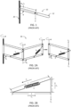
- FIG. 2A provides a conceptual diagram of a gravity-balancing mechanism 30 including a serial chain of n parallelograms (e.g., four-bar linkages), which constrain motion between the links in a way that allows translation but not rotation of opposite links. Because of this property, if one link in a parallelogram is mechanically grounded, any torque applied to its opposite side (i.e ., the freely moving side) is transmitted directly through the mechanism to ground.
- a gravity compensating spring ( k 1 ...k n ) may be attached diagonally within each parallelogram between attachment points A and B. When coupled in such a manner, the spring provides a lifting force ( F b ) that opposes the gravitational force ( F g ) on the load.
- FIG. 2B illustrates the tension and compression forces ( F a , F b , and F c ) generated within a single parallelogram shown in FIG. 2A when a gravity compensating spring ( k i ) is attached diagonally between two links of the parallelogram at spring attachment points A and B.
- the forces generated within the parallelogram are related to the geometric lengths of a triangle formed between the gravity compensating spring and the links to which it is connected.
- the tension and compression forces may be expressed as: F a a ⁇ F b b ⁇ F c c , where ' a ' is the length between attachment point A and one corner of the parallelogram, ' b ' is the length between attachment point B and the same corner of the parallelogram, and ' c ' is the length of the spring.
- ' F c ' is the restoring force generated by a spring of length ' c '
- ' F b ' is the lifting force generated along length ' b ' that opposes the gravitational load force ( F g )
- ' F a ' is the tension force generated along length ' a '.
- the lifting force ( F b ) is independent of spring length (c), and therefore, constant for any orientation ( ⁇ ).
- gravity-balancing mechanism 30 exhibits iso-elasticity, since no external force or torque is needed to balance the weight at any orientation ( ⁇ ) of the mechanism for a fixed gravitational load force ( F g ).
- a real spring having a non-zero free length requires a prohibitively large spring to reproduce ideal spring characteristics that are independent of orientation ( ⁇ ).
- the lifting force ( F b ) provided by the spring is often too low at upper positions and too high at lower positions, resulting in a gravity-balancing mechanism 30 that does not exhibit iso-elastic behavior at all orientations.
- adjustable knobs that may be rotated by an operator to: (a) raise/lower the spring attachment point to increase/decrease the lifting force provided by the spring, and/or (b) pivot the spring attachment point away from/toward the side of the link to increase/decrease gravity-balancing at upper and lower positions.
- the manual spring adjustment means disclosed in the '016 Patent can be used to improve the iso-elastic behavior of the support arm at extreme positions
- the operator of the camera stabilizing device is responsible for adjusting the spring adjustment mechanism and applying the force necessary to accelerate and manipulate a specific payload. Since the operator must adjust the spring position manually ( e.g. , by adjusting one or more knobs) to accommodate a specific payload, the iso-elastic support arm disclosed in the '016 Patent cannot support payloads that change dynamically throughout operation. While this is acceptable for cameramen applications, it is insufficient for robotic manipulators that handle constantly changing payloads.
- the iso-elastic support arm disclosed in the '016 Patent can be used to position a payload (e.g., a camera) in Cartesian space, the parallelogram links remain parallel to the base frame of the support arm, and therefore, cannot change the orientation of the payload.
- a payload e.g., a camera
- US 10 040 207 B1 discloses an apparatus according to the preamble of claim 1.
- an apparatus in accordance with the present invention includes a four-bar linkage mechanism, at least one gravity compensating spring, a spring adjustment mechanism and a spring adjustment actuator.
- the apparatus may be a spring compensated joint included, for example, within a robotic manipulator. In other embodiments, the apparatus may be a gravity compensating mechanism.
- the four-bar linkage mechanism includes an upper link arranged parallel to a lower link and a first side link arranged parallel to a second side link.
- the first and second side links are coupled between the upper and lower links at distal ends thereof to form a parallelogram structure.
- the at least one gravity compensating spring is coupled to the parallelogram structure, and is attached between two links of the four-bar linkage mechanism at two different spring attachment points.
- the at least one gravity compensating spring may include two gravity compensating springs, each of which may be coupled diagonally within the parallelogram structure and attached between two links of the four-bar linkage mechanism at two different spring attachment points.
- the spring adjustment mechanism is coupled to one end of the at least one gravity compensating spring to adjust a position of at least one of the spring attachment points.
- the spring adjustment actuator is coupled to move the spring adjustment mechanism to alter the position of the at least one spring attachment point and dynamically alter an amount of gravity compensating torque applied by the gravity compensating spring when a payload handled by the apparatus changes.
- the spring adjustment mechanism may be implemented in a variety of different ways.
- the spring adjustment mechanism may include a slider, which is configured to adjust the position of the at least one spring attachment point by translating the at least one spring attachment point along an axis substantially parallel to the first side link, or along an axis substantially parallel to the lower link.
- the spring adjustment mechanism may include a slider coupled to an additional four-bar linkage.
- the additional four-bar linkage may extend the at least one spring attachment point beyond a boundary of the first side link and enable the slider to translate the at least one spring attachment point along an axis, which is not parallel to an axis extending through the first side link.
- the apparatus may further include an inertial actuator, which may be coupled between links of the four-bar linkage mechanism to effectuate rotational movement of the four-bar linkage mechanism and apply an adjustable amount of force to accelerate and manipulate the payload.
- an inertial actuator which may be coupled between links of the four-bar linkage mechanism to effectuate rotational movement of the four-bar linkage mechanism and apply an adjustable amount of force to accelerate and manipulate the payload.
- the inertial actuator may be implemented in a variety of different ways.
- the inertial actuator may be a prismatic linear actuator, which is coupled diagonally between the lower link and the first side link of the four-bar linkage mechanism.
- the inertial actuator may be a rotational actuator comprising a stator and a rotor, wherein the stator is coupled to the first side link and the rotor is coupled to the lower link, or vice versa.
- the inertial actuator may be a prismatic linear actuator, which is coupled to the upper link and arranged, so that a longitudinal axis of the inertial actuator is parallel with the upper link.
- the apparatus may further include a slider crank mechanism, which is coupled between one end of the inertial actuator and the first side link.
- the slider crank mechanism may be configured to convert linear motion of the inertial actuator into rotational motion of the apparatus.
- the apparatus may further include a slider crank mechanism and an additional four-bar linkage, which are coupled between the inertial actuator and one or more links of the four-bar linkage mechanism.
- the slider crank mechanism and the additional four-bar linkage may be configured to convert linear motion of the inertial actuator into rotational motion of the apparatus.
- a robotic manipulator may generally include a serial chain of actuators and a plurality of spring compensated joints that enable the robotic manipulator to manipulate the position and the orientation of its payload in a spatial environment.
- Each spring compensated joint of the robotic manipulator according to the present invention includes a four-bar linkage mechanism, at least one gravity compensating spring, a spring adjustment mechanism and a spring adjustment actuator.
- the four-bar linkage mechanism includes an upper link arranged parallel to a lower link and a first side link arranged parallel to a second side link.
- the first and second side links may be coupled between the upper and lower links at distal ends thereof to form a parallelogram structure.
- the at least one gravity compensating spring is coupled between two links of the four-bar linkage mechanism at two different spring attachment points to provide a lifting force ( F b ) in a direction opposing a gravitational force ( F g ) on the payload.
- the spring adjustment mechanism is coupled to one end of the at least one gravity compensating spring and is configured to alter a position of at least one of the spring attachment points.
- the spring adjustment actuator is coupled to move the spring adjustment mechanism, so as to alter the position of the at least one spring attachment point and dynamically adjust the amount of lifting force ( F b ) provided by the gravity compensating spring.
- the at least one gravity compensating spring may include two gravity compensating springs, each of which may be coupled diagonally between two links of the four-bar linkage mechanism at two different spring attachment points.
- the spring adjustment mechanism may include a lead screw positioned adjacent and parallel to the first side link, and a slider coupled to the lead screw and to the one end of the at least one gravity compensating spring.
- the spring adjustment actuator may be coupled to the lead screw and configured to adjust the position of the at least one spring attachment point by translating the lead screw up/down along an axis, which is substantially parallel to the first side link.
- the robotic manipulator may further include a sensor and a feedback controller, which is coupled to the sensor and the spring adjustment actuator.
- the sensor may be coupled to measure the force and/or torque of a payload handled by the robotic manipulator.
- the feedback controller may be configured to use an output of the sensor to alter the at least one spring attachment point and dynamically adjust the lifting force in real-time to compensate for gravitational load forces on dynamically varying payloads.
- each spring compensated joint may further include an inertial actuator, which is coupled between links of the four-bar linkage mechanism to effectuate rotational movement of the four-bar linkage mechanism and apply an adjustable amount of force to accelerate and manipulate a payload handled by the robotic manipulator.
- the inertial actuator may be a prismatic linear actuator, which is coupled to the upper link of the four-bar linkage mechanism and arranged, so that a longitudinal axis of the inertial actuator is parallel with the upper link.
- each spring compensated joint may further include a slider crank mechanism and a Hoeken's linkage, which are coupled between the inertial actuator and one or more links of the four-bar linkage mechanism. In such embodiments, the slider crank mechanism and the Hoeken's linkage may be configured to convert linear motion of the inertial actuator into rotational motion of the spring compensated joint.
- the robotic manipulator may further include a sensor and a feedback controller, which is coupled to the sensor and the inertial actuator.
- the sensor may be coupled to measure the force and/or torque of a payload handled by the robotic manipulator.
- the feedback controller may be configured to use an output of the sensor to dynamically adjust a force applied by the inertial actuator to manipulate and accelerate dynamically varying payloads.
- the robotic manipulator may include a plurality of spring compensated joints configured to move the robotic manipulator up and down, a plurality of yaw actuators configured to pivot the robotic manipulator side-to-side, a pitch actuator configured to move an end effector up and down, and a roll actuator configured to rotate the end effector.
- the robotic manipulator may include a first yaw actuator coupled to mechanical ground, a first spring compensated joint coupled between the first yaw actuator and a second yaw actuator, a second spring compensated joint coupled between the second yaw actuator and a third yaw actuator, a pitch actuator coupled to the third yaw actuator, a roll actuator coupled to the pitch actuator and an end effector coupled to the roll actuator.
- the robotic manipulator may include a plurality of spring compensated joints configured to move the robotic manipulator up and down, a plurality of yaw actuators configured to pivot the robotic manipulator side-to-side, a serial chain of actuators and an end effector.
- the robotic manipulator may include a first yaw actuator coupled to mechanical ground, a first spring compensated joint coupled between the first yaw actuator and a second yaw actuator, a second spring compensated joint coupled between the second yaw actuator and the serial chain of actuators, which are further coupled to the end effector.
- the serial chain of actuators may include a first actuator coupled to one end of the second spring compensated joint, a second actuator coupled to the first actuator, and a third actuator coupled to the second actuator.
- the first actuator may be configured to rotate the end effector about a tilted axis
- the second actuator may be configured to rotate the end effector up and down
- the third actuator may be configured to rotate the end effector side-to-side.
- FIGS. 3-13 depict various embodiments of a robotic manipulator including a plurality of spring compensated joints.
- each joint of the disclosed robotic manipulator may include a four-bar linkage mechanism, at least one gravity compensating spring coupled between links of the four-bar linkage mechanism at two different spring attachment points, a spring adjustment mechanism coupled to one end of the gravity compensating spring and configured to adjust a position of at least one of the spring attachment points, a spring adjustment actuator coupled to alter the position of the at least one spring attachment point and adjust the lifting force ( F b ) provided by the spring, and an inertial actuator coupled between links of the four-bar linkage mechanism to effectuate rotational movement of the four-bar linkage mechanism and to apply an adjustable amount of force to accelerate and manipulate a payload handled by the robotic actuator.
- the robotic manipulator depicted in FIGS. 3-13 uses active actuation and feedback control to adjust the amount of lifting force provided by the spring and dynamically alter the amount of gravity compensating torque applied by the spring when the payload changes. This enables the disclosed robotic manipulator to maintain gravity balance with dynamically varying payloads, and reduces the actuator efforts needed to accelerate and manipulate a payload regardless of weight.
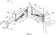
- FIG. 3 is a conceptual diagram of a robotic manipulator 100 having a plurality of spring compensated joints 110 in accordance with one embodiment of the present disclosure.
- robotic manipulator 100 includes a first spring compensated joint 110A and a second spring compensated joint 110B.
- first spring compensated joint 110A and a second spring compensated joint 110B.
- second spring compensated joint 110B Although only two spring compensated joints are shown in FIG. 3 , it is expressly noted that robotic manipulator 100 may include one or more additional joints and actuators to provide greater range of motion.
- each spring compensated joint 110 of robotic manipulator 100 includes a four-bar linkage mechanism (111, 112, 113, 114), a gravity compensating spring 115, a spring adjustment mechanism 116, a spring adjustment actuator 117 and an inertial actuator 118.
- one or more components of the disclosed spring compensated joint may be configured and/or implemented differently than what is expressly depicted in FIG. 3 , while retaining the functionality described herein. The present disclosure is considered to encompass all such configurations and alternative implementations.
- a first spring compensated joint 110A is coupled at one end to a first yaw actuator 120A, which is coupled to mechanical ground.
- An opposite end of the first spring compensated joint 110A is coupled to a second yaw actuator 120B, which in turn, is coupled to one end of the second spring compensated joint 110B.
- An opposite end of the second spring compensated joint 110B is coupled to a third yaw actuator 120C, which in turn, is coupled to pitch actuator 130, roll actuator 140 and end effector 150.
- the yaw actuators 120, pitch actuator 130, roll actuator 140 included within the robotic manipulator 100 are inertial actuators, which may be driven to change the position and orientation of the manipulator.
- the robotic manipulator 100 shown in FIG. 3 includes serial chain of spring compensated joints and actuators, which enable the robotic manipulator to control the position and the orientation of its payload in a 3-D spatial environment.
- each yaw actuator 120A, 120B and 120C is configured to pivot the robotic manipulator side-to-side in a plane orthogonal to the gravity vector, while the spring compensated joints 110A and 110B are configured to move the robotic manipulator up and down by adjusting the joint orientation angle ⁇ .
- yaw actuator 120C is configured to pivot the end effector 150 side-to-side
- pitch actuator 130 is configured to rotate the end effector 150 up and down
- roll actuator 140 is configured to rotate the end effector around its primary axis.
- yaw actuators 120, pitch actuator 130 and roll actuator 140 may be implemented with substantially any type of rotary actuator (e.g. , electric, hydraulic, etc.).
- yaw actuators 120, pitch actuator 130 and roll actuator 140 may each be implemented with some form of geared electromagnetic rotary actuator including an electric motor coupled to a gearbox or drivetrain.
- the yaw actuators 120 may be implemented with a linear actuator if additional means are provided for converting the linear motion of the actuator into rotational motion. For example, if yaw actuators 120 are implemented with linear actuators, an additional slider crank mechanism can be provided at each joint to convert the linear motion of the linear actuator into rotational motion at the joint.
- a substantially different configuration of actuators may be used at the freely moving end (e.g., the wrist portion) of the robotic manipulator 100 in lieu of yaw actuator 120C, pitch actuator 130 and roll actuator 140.
- an alternative wrist design may include three rotary actuators coupled in series between the last spring compensated joint (e.g. , joint 110B) and the end effector 150.
- a first rotary actuator e.g., a 45° actuator
- a first rotary actuator coupled to the last spring compensated joint may be configured to rotate the end effector 150 about a tilted axis, which is displaced from the Z-axis by an acute angle (e.g., about 45°).
- a second rotary actuator (e.g., a pitch actuator) coupled to the first rotary actuator may be configured to rotate the end effector 150 up and down
- a third actuator e.g., a yaw actuator coupled to the first rotary actuator may be configured to rotate the end effector 150 side to side.
- the first, second and third rotary actuators enable end effector 150 to rotate along its primary axis (e.g. , the vertical axis), which is helpful when picking up an object and rotating about its primary axis.
- the first, second and third rotary actuators also enable continuous rotation of the last joint in the chain, which is helpful for tasks like turning a screwdriver.
- Two common manipulation poses are also accommodated with the alternative wrist design: 1) top down manipulation (e.g. , picking up something from overhead), and 2) horizontal manipulation (e.g. , picking up something sideways, such as an object located on a horizontally accessible shelf).
- each spring compensated joint 110A and 110B includes a four-bar linkage mechanism comprising an upper link 111 arranged parallel to a lower link 112, and a first side link 113 arranged parallel to a second side link 114.
- the first and second side links 113 and 114 are coupled between the upper and lower links 111 and 112 at distal ends thereof to form a parallelogram structure, which constrains motion between the links of the four-bar linkage mechanism in a way that allows translation, but not rotation, of opposite links. Because of this property, any torque applied to end effector 150 ( i.e. , at the freely moving end) is transmitted directly through the serially coupled actuators and joints of robotic manipulator 100 to mechanical ground.
- gravity compensating spring 115 may be coupled to the parallelogram structure of each spring compensated joint 110A/110B between two links of the four-bar linkage mechanism.
- spring 115 is coupled diagonally between attachment point A on lower link 112 and attachment point B on first side link 113.
- spring 115 provides a lifting force ( F b ) in a direction opposing the gravitational load force ( F g ).
- F b gravitational load force
- the gravity compensating spring 115 may provide a lifting force ( F b ) without being attached diagonally between links of the four-bar linkage mechanism, as shown in FIG. 3 .
- the gravity compensating spring 115 may be alternatively oriented and attached, for example, to a cable that spans the four-bar linkage mechanism diagonally via pulleys. Together, the gravity compensating spring, cable and pulleys may provide the lifting force ( F b ) needed to oppose the gravitational load force ( F g ). In some embodiments, one or more characteristics (e.g., length, stiffness, etc.) of the gravity compensating spring 115 may be selected to counter-balance the weight of robotic manipulator 100 and its payload, so that it ideally behaves as if its motion is in a gravity-less environment when carrying a payload.
- characteristics e.g., length, stiffness, etc.
- each spring compensated joint 110A and 110B may include a spring adjustment mechanism 116 and a spring adjustment actuator 117, as shown in FIG. 3 .
- spring adjustment mechanism 116 and spring adjustment actuator 117 may be configured to alter a position of one or more attachment points of the gravity compensating spring 115, so as to adjust the amount of lifting force ( F b ) provided thereby.
- spring adjustment mechanism 116 includes a lead screw 116a which is positioned adjacent and parallel to the first side link 113, and a slider 116b which is fixedly attached to the lead screw.
- One end of the gravity compensating spring 115 is attached to lower link 112 at spring attachment point A, while the other end of the spring is attached to slider 116b at spring attachment point B.
- spring adjustment actuator 117 is coupled to lead screw 116a and configured to adjust the position of spring attachment point B by translating the lead screw up/down along an axis parallel to the first side link 113. By driving the lead screw (and thus, the slider 116b fixedly attached thereto) to a desired position, spring adjustment actuator 117 provides the active actuation needed to alter the position of spring attachment point B and adjust the lifting force ( F b ) provided by the gravity compensating spring 115.
- spring adjustment actuator 117 may be a linear actuator having an electric motor, which is directly or indirectly connected to lead screw 116a.
- the motor shaft of the linear actuator may be mounted directly onto a distal end of lead screw 116a to drive the lead screw up and down.
- a belt system may be used to connect the motor shaft of the linear actuator to the lead screw 116a, as shown in FIG. 3 .
- Spring adjustment actuator 117 is configured to provide an adjustable lifting force ( F b ) to counteract substantially 100% of the gravity torque on robotic manipulator 100 regardless of payload.
- a sensor and feedback controller may be coupled to spring adjustment actuator 117 (as shown, e.g., in FIG. 11 ) to adjust the lifting force needed to compensate for gravitational load forces on dynamically varying payloads.
- the spring adjustment mechanism 116, the spring adjustment actuator 117, and the sensor and feedback controller may be used to dynamically adjust the spring position in real-time, so that robotic manipulator 100 is nearly perfectly gravity compensated regardless of payload.
- each spring compensated joint 110A/110B may include an inertial actuator 118, which is configured to apply an adjustable amount of force to accelerate and manipulate the payload.
- spring adjustment actuator 117 provides a gravity compensating torque that offsets substantially 100% of the gravity torque (i.e ., the largest torque source) on robotic manipulator 100
- inertial actuator 118 only needs to compensate for the remaining torque sources (i.e ., inertial, friction and external torques) when moving the robotic manipulator from point to point. This greatly reduces the effort and energy consumed by the inertial actuator 118.
- the inertial actuator 118 is not coupled to the gravity compensating spring 115 or configured to alter a position of the spring attachment points A and B. Instead, the inertial actuator 118 is coupled between links of the spring compensated joint 110 to effectuate rotational movement of the joint and apply an adjustable amount of force to accelerate and manipulate the payload.
- the inertial actuator 118 is coupled diagonally between the lower link 112 and first side link 113 of the spring compensated joint 110, and is arranged above and substantially in parallel with the gravity compensating spring 115. When coupled in such a manner, the inertial actuator 118 is configured to actively adjust the magnitude of the force applied by the inertial actuator to move the robotic manipulator 100 up/down and to accelerate and deaccelerate the joint while counteracting external disturbances.
- the inertial actuator 118 shown in the embodiment of FIG. 3 may be compressed to increase the magnitude of the acceleration force applied to the first side link 113 to raise the opposing side of the joint (i.e ., the side comprising second side link 114), thereby increasing the joint orientation angle ⁇ and moving the robotic manipulator 100 in an upward direction.
- the inertial actuator 118 may be extended to decrease the magnitude of the acceleration force applied to the first side link 113 to lower the opposing side of the joint, thereby decreasing the joint orientation angle ⁇ and moving the robotic manipulator 100 in a downward direction.
- the inertial actuator 118 may be configured to increase or decrease the force needed to accelerate/deaccelerate and manipulate a fixed payload in a desired direction.
- a sensor and feedback controller may be coupled to the inertial actuator 118 (as shown, e.g., in FIG. 11 ) to dynamically adjust the force needed to manipulate and accelerate payloads regardless of weight.
- the inertial actuator 118 shown in FIG. 3 may be a prismatic linear actuator having an electric motor mechanically coupled to one end of a screw drive mechanism.
- the screw drive mechanism may be coupled to a lead nut, which may be coupled to lower link 112 near spring attachment point A.
- the inertial actuator 118 may be configured to translate the second side link 114 with respect to the first side link 113 to effectuate rotational motion of the joint. It is noted, however, that inertial actuator 118 is not strictly limited to a prismatic linear actuator in all embodiments, and may be alternatively implemented with other types of actuators known in the art.
- inertial actuator 118 may be coupled to the spring compensated joint 110 in a manner that differs from that expressly shown in FIG. 3 .
- FIGS. 7-10 illustrate how different types of inertial actuators 118 may be coupled to spring compensated joint 110 in accordance with various embodiments of the present disclosure.
- FIG. 3 illustrates only one example embodiment of a spring compensated joint 110 comprising a four-bar linkage mechanism (111, 112, 113, 114), a gravity compensating spring 115, a spring adjustment mechanism 116 configured to alter a position of one or more attachment points of the gravity compensating spring 115, a spring adjustment actuator 117 configured to dynamically adjust a lifting force ( F b ) provided by the gravity compensating spring 115, and an inertial actuator 118 configured to apply a force (e.g. , an acceleration force) needed to accelerate and manipulate a payload regardless of weight.
- robotic manipulator 100 is not strictly limited to the particular arrangement and implementation of components shown in FIG. 3 .
- robotic manipulator 100 may include additional spring compensated joints and actuators to provide greater range of motion, where each joint includes a four-bar linkage mechanism (111, 112, 113, 114), a gravity compensating spring 115, a spring adjustment mechanism 116, a spring adjustment actuator 117 and an inertial actuator 118.
- each joint includes a four-bar linkage mechanism (111, 112, 113, 114), a gravity compensating spring 115, a spring adjustment mechanism 116, a spring adjustment actuator 117 and an inertial actuator 118.
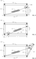
- FIGS. 4-6 illustrate various embodiments of spring adjustment mechanisms 116 that may be included within a spring compensated joint 110 in accordance with the present disclosure.
- a spring adjustment actuator 117 will be mechanically coupled to the spring adjustment mechanism 116 shown in FIGS. 4-6 to alter the position of the one or more spring attachment points ( i.e ., A, B, or A and B) and dynamically adjust the lifting force ( F b ) provided by the gravity compensating spring 115 in real-time.
- FIGS. 3 and 4-6 example embodiments of a spring adjustment mechanism 116 are shown in FIGS. 3 and 4-6 , these embodiments are not exhaustive or inclusive of all potential implementations of a spring adjustment mechanism in accordance with the present disclosure.
- other embodiments of spring adjustment mechanisms can be coupled to the spring compensated joints 110 disclosed herein to alter the position of one or more spring attachment points ( i.e ., A, B, or A and B) and adjust the lifting force ( F b ) provided by the gravity compensating spring 115.
- the present disclosure is considered to encompass all such embodiments and implementations.
- FIG. 4 depicts a simplified representation of the spring adjustment mechanism 116 shown in FIG. 3 .
- slider 116b is configured to slide along an axis extending through the first side link 113 to alter the position of spring attachment point B.
- slider 116b may be configured to surround and slide along an outer perimeter of the first side link 113.
- slider 116b may be configured to slide within a groove formed within first side link 113.
- the position of spring attachment point B may be changed to increase or decrease length 'b', thereby increasing or decreasing the lifting force ( F b ) provided by the gravity compensating spring 115.
- FIG. 5 depicts a simplified representation of a spring adjustment mechanism 116, which differs from the one shown in FIGS. 3 and 4 by positioning the spring adjustment mechanism at spring attachment point A.
- one end of the gravity compensating spring 115 is attached to slider 116b at spring attachment point A, while the other end of the spring is attached to the first side link 113 at spring attachment point B.
- slider 116b is configured to slide along an axis extending through lower link 112 to alter the position of spring attachment point A.
- slider 116b may be configured to surround and slide along an outer perimeter of the lower link 112, or may be configured to slide within a groove formed within the lower link 112.
- the position of spring attachment point A may be adjusted to increase or decrease length ' a ', thereby increasing or decreasing the lifting force ( F b ) provided by the gravity compensating spring 115.
- FIG. 6 depicts an alternative embodiment of a spring adjustment mechanism 116 that may be included within a spring compensated joint 110 in accordance with the present disclosure.
- the spring adjustment mechanism 116 shown in FIG. 6 includes a slider 116b, which is coupled to alter the position of spring attachment point B.
- the spring adjustment mechanism 116 shown in FIG. 6 includes an additional four-bar linkage 119 coupled to slider 116b.
- the four-bar linkage 119 extends the spring attachment point B beyond the boundary of the first side link 113 and allows translational movement of the slider 116b along an axis, which is not parallel to the axis extending through the first side link 113.
- the position of spring attachment point B may be adjusted to improve the "quality" of gravity compensation when non-ideal springs with non-zero free lengths and non-zero preload forces are used.
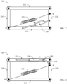
- FIGS. 7-10 illustrate various embodiments of inertial actuators 118 that may be included within a spring compensated joint 110 in accordance with the present disclosure.
- the inertial actuator 118 shown in FIGS. 7-10 may be generally configured to effectuate rotational motion of the joint and apply a force (e.g. , an acceleration force) needed to accelerate and manipulate a payload.
- a sensor and feedback controller (as shown, e.g., in FIG. 11 ) may be coupled to the inertial actuator 118 shown in FIGS. 7-10 to dynamically adjust the amount of force needed to accelerate and manipulate a payload, while rejecting or compensating for external disturbances (such as friction and external torques) on the joint.
- an inertial actuator 118 is shown in FIGS. 3 and 7-10 , these embodiments are not exhaustive or inclusive of all potential implementations of an inertial actuator in accordance with the present disclosure.
- other types of inertial actuators and mechanisms such as a Hoeken's linkage can be used to couple an inertial actuator to a spring compensated joint 110.
- the present disclosure is considered to encompass all such embodiments and implementations.
- FIG. 7 depicts a simplified representation of a spring compensated joint 110 comprising an inertial actuator 118.
- the inertial actuator 118 shown in FIG. 7 is coupled in parallel with the gravity compensating spring 115 and attached diagonally between the lower link 112 and first side link 113 of the spring compensated joint 110.
- the inertial actuator 118 shown in FIG. 7 may be a prismatic linear actuator having an electric motor, which is mechanically coupled to one end of a screw drive mechanism, as described above.
- the inertial actuator 118 is configured to translate the second side link 114 with respect to the first side link 113 to effectuate rotational motion of the joint and actively adjust the magnitude of the force applied by the inertial actuator to accelerate the joint and move the robotic manipulator 100 up/down.
- the embodiment shown in FIG. 7 differs slightly from the one shown in FIG. 3 by arranging the inertial actuator 118 below the gravity compensating spring 115, as opposed to above the spring.
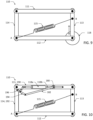
- FIG. 8 depicts a simplified representation of a spring compensated joint 110 comprising a first alternative embodiment of an inertial actuator 118 in accordance with the present disclosure.
- the inertial actuator 118 shown in FIG. 10 may be a prismatic linear actuator having an electric motor, which is mechanically coupled to one end of a screw drive mechanism.
- the inertial actuator 118 shown in FIG. 8 is arranged along, and in parallel with, the upper link 111 of the spring compensated joint 110.
- One end of the inertial actuator 118 is coupled to a slider crank mechanism comprising a slider 160 and additional link 170.
- Slider 160 is configured to move linearly along an axis extending longitudinally through the upper link 111.
- the additional link 170 is coupled diagonally between slider 160 and the first side link 113 of the spring compensated joint 110.
- the inertial actuator 118 is configured to actively adjust the magnitude of the force applied by the inertial actuator to accelerate the joint and move the robotic manipulator 100 up/down.
- the inertial actuator 118 shown in FIG. 8 may be compressed to increase the magnitude of the acceleration force applied to the first side link 113 to raise the opposing side of the joint ( i.e ., the side comprising second side link 114), thereby increasing the joint orientation angle ⁇ and moving the robotic manipulator 100 in an upward direction.
- the inertial actuator 118 may be extended to decrease the magnitude of the acceleration force applied to the first side link 113 to lower the opposing side of the joint, thereby decreasing the joint orientation angle ⁇ and moving the robotic manipulator 100 in a downward direction.
- FIG. 9 depicts a simplified representation of a spring compensated joint 110 comprising a second alternative embodiment of an inertial actuator 118 in accordance with the present disclosure.
- the inertial actuator 118 shown in FIG. 9 is implemented as a rotational actuator, instead of a linear actuator.
- the rotational actuator 118 shown in FIG. 9 is coupled between the first side link 113 and lower link 112 of the spring compensated joint 110.
- a stator or housing of the rotational actuator 118 shown in FIG. 9 may be coupled to the first side link 113, while the rotor is coupled to the lower link 112 (or vice versa).
- the rotational actuator 118 shown in FIG. 9 is configured to actively adjust the magnitude of the torque applied between links 112 and 113 to accelerate the joint and move the robotic manipulator 100 up/down.
- FIG. 10 depicts a simplified representation of a spring compensated joint 110 comprising a third alternative embodiment of an inertial actuator 118 in accordance with the present disclosure.
- the inertial actuator 118 shown in FIG. 10 may be a prismatic linear actuator having an electric motor, which is mechanically coupled to one end of a screw drive mechanism.
- the inertial actuator 118 shown in FIG. 10 may also be coupled to the upper link 111 and arranged, such that a longitudinal axis of the inertial actuator is parallel with the upper link.
- the inertial actuator 118 shown in FIG. 10 is coupled to a slider crank mechanism and an additional four-bar linkage to more efficiently convert linear motion of the inertial actuator into rotational motion of the spring compensated joint 110.
- the slider crank mechanism includes a slider 180 and a crank 182.
- the additional four-bar linkage shown in FIG. 10 is implemented as a Hoeken's linkage, including a first link 190, a second link 192, a third link 194 and a fourth link 196.
- the first link 190 of the Hoeken's linkage is the upper link 111 of the four-bar linkage mechanism
- the second link 192 of the Hoeken's linkage is the second side link 114 of the four-bar linkage mechanism.
- inertial actuator 118 is implemented as a prismatic linear actuator having an electric motor 118a mechanically coupled to one end of a screw drive mechanism 118b.
- the screw drive mechanism 118b of inertial actuator 118 is coupled to the slider 180, which in turn, is coupled to the crank 182 of the slider crank mechanism.
- slider 180 e.g. , a lead nut
- slider 180 slides along the screw drive mechanism 118b, causing one end of the crank 182 to slide in a direction parallel with the upper link 111 of the four-bar linkage mechanism and the first link 190 of the Hoeken's linkage.
- crank 182 is rotationally coupled to the third link 194 of the Hoeken's linkage, which in turn, is rotationally coupled to the second side link 114 of the four-bar linkage mechanism and the second link 192 of the Hoeken's linkage.
- One end of the fourth link 196 is rotationally coupled to the third link 194, while the opposite end of the fourth link 196 is rotationally coupled to upper link 111 of the four-bar linkage mechanism and the first link 190 of the Hoeken's linkage.
- the Hoeken's linkage (190, 192, 194, 196) converts linear motion of inertial actuator 118 into rotational motion of the spring compensated joint 110 by translating the second side link 114 of the four-bar linkage mechanism with respect to first side link 113.
- inertial actuator 118 may be compressed to compress the Hoeken's linkage and increase the magnitude of the acceleration force applied to the second side link 114 to pull the second side link down, thereby decreasing the joint orientation angle ⁇ and moving the robotic manipulator 100 in a downward direction.
- inertial actuator 118 may be extended to elongate the Hoeken's linkage and decrease the magnitude of the acceleration force applied to the second side link 114 to push the second side link up, thereby increasing the joint orientation angle ⁇ and moving the robotic manipulator 100 in an upward direction.
- Linear actuators driving rotary joints typically have position-dependent torque profiles due to the nonlinear relationship between linear displacement of the actuator and rotational motion of the joint. This nonlinear relationship can be advantageous in situations where torques experienced by the rotational joint share a similar nonlinear profile relative to angular displacement.
- inertial actuator 118 shown in FIG. 10 inertial torques are not dependent on joint angle, and therefore, a non-linear mapping between linear and rotational space is not desirable.
- the Hoeken's linkage (190, 192, 194, 196) works well in this situation because it is a mechanism that couples linear motion to rotational motion with a nearly constant speed ratio, meaning that the effective joint torque of the inertial actuator 118 remains constant throughout the range of motion of the spring compensated joint 110.
- the Hoeken's linkage shown in FIG. 10 provides a more efficient mechanism for converting linear motion of the inertial actuator 118 into rotational motion of the spring compensated joint 110 compared, for example, to the previous embodiment shown in FIG. 8 .
- FIGS. 3-6 Various embodiments of spring adjustment mechanisms 116 in accordance with the present disclosure are shown in FIGS. 3-6 and described above. It is noted that, while illustrated as separate embodiments, one or more of the spring adjustment mechanisms 116 shown in FIGS. 3-6 may be combined within a single embodiment to alter the position of one or more spring attachment points ( i.e ., A, B, or A and B).
- FIGS. 3 and 7-10 Various embodiments of inertial actuators 118 in accordance with the present disclosure are shown in FIGS. 3 and 7-10 and described above. It is noted that, while illustrated as separate embodiments, one or more of the inertial actuators 118 shown in FIGS. 3 and 7-10 may be combined within a single embodiment to adjust a magnitude of one or more forces (e.g., F a , F b , and/or F c of FIG. 2B ) generated within the spring compensated joint 110.
- forces e.g., F a , F b , and/or F c of FIG. 2B
- a spring compensated joint 110 in accordance with the present disclosure may combine any of the spring adjustment mechanisms 116 shown in FIGS. 4-6 with any of the inertial actuators 118 shown in FIGS. 7-10 .
- FIG. 11 is a practical implementation of a robotic manipulator 200 including a plurality of spring compensated joints 210A/B in accordance with one embodiment of the present disclosure.
- FIG. 12 provides a side view of spring compensated joint 210B, illustrating example actuators (230, 240, 245) that may be included within the wrist portion of the robotic manipulator 200 to effectuate movement of the end effector (not shown in FIGS. 11 and 12 ).
- FIG. 13 provides a side cross-sectional view of spring compensated joint 210B to better illustrate various internal components included within the joint.
- the robotic manipulator 200 shown in FIG. 11 includes a serial chain of spring compensated joints 210 and actuators, which enable the robotic manipulator to control the position and orientation of a payload in a 3-D spatial environment.
- robotic manipulator 200 includes a first spring compensated joint 210A and a second spring compensated joint 210B.
- first spring compensated joint 210A and a second spring compensated joint 210B.
- robotic manipulator 200 may include one or more additional joints and actuators to provide greater range of motion.
- each spring compensated joint 210 of robotic manipulator 200 includes a four-bar linkage mechanism (211, 212, 213, 214), at least one gravity compensating spring 215, a spring adjustment mechanism 216, a spring adjustment actuator 217 and an inertial actuator 218.
- one or more components of the disclosed spring compensated joint may be configured and/or implemented differently than what is expressly depicted in FIG. 11 , while retaining the functionality described herein. The present disclosure is considered to encompass all such configurations and alternative implementations.
- a first spring compensated joint 210A is coupled at one end to a first yaw actuator 220A, which is coupled to mechanical ground.
- An opposite end of the first spring compensated joint 210A is coupled to a second yaw actuator 220B, which is coupled to one end of a second spring compensated joint 210B.
- a serial chain of actuators e.g. , a first actuator 230, a second actuator 240, and a third actuator 245 is coupled between an opposite end of the second spring compensated joint 210B and the end effector (not shown).
- spring compensated joints 210A and 210B are configured to move the robotic manipulator 200 up and down by adjusting the joint orientation angle ⁇ .
- Yaw actuators 220A and 220B are configured to pivot the robotic manipulator 200 side-to-side in a plane orthogonal to the gravity vector ( F g ).
- the serial chain of actuators e.g. , the first actuator 230, second actuator 240, and third actuator 245) included within the wrist portion of the robotic manipulator 200 are configured to effectuate movement of the end effector (not shown).
- the first actuator 230 is coupled to the second spring compensated joint 210B and configured to rotate the end effector about a tilted axis, which is displaced from the Z-axis by an acute angle (e.g., about 45° from vertical).
- the second actuator 240 e.g., a pitch actuator
- the third actuator 245 is coupled to the second actuator 240 and configured to rotate the end effector side-to-side.
- the actuators (e.g. , 220A/B, 230, 240 and/or 245) included within robotic manipulator 200 may each be implemented with a type of rotary actuator (e.g., electric, hydraulic, etc.).
- actuators 220A/B, 230, 240 and 245 may each be implemented with some form of geared electromagnetic actuator including an electric motor coupled to a gearbox or drivetrain.
- one or more of the actuators included within robotic manipulator 200 may implemented with linear actuators.
- yaw actuators 220A and 220B may implemented with linear actuators, if an additional slider crank mechanism is provided at each joint to convert the linear motion of the linear actuators into rotational motion at the joints.
- each of the spring compensated joints 210A/B included within robotic manipulator 200 may generally include a four-bar linkage mechanism (211, 212, 213, 214), at least one gravity compensating spring 215, a spring adjustment mechanism 216, a spring adjustment actuator 217 and an inertial actuator 218.
- the at least one gravity compensating spring 215 may be coupled between two different links of the four-bar linkage mechanism (211, 212, 213, 124) at two different spring attachment points (A, B).
- the spring adjustment mechanism 216 may be coupled to one end of the at least one gravity compensating spring 215 and configured to adjust a position of at least one of the spring attachment points (A and/or B) to adjust a lifting force ( F b ) provided by the spring 215.
- the spring adjustment actuator 217 may be coupled to move the spring adjustment mechanism 216 to alter the position of the at least one spring attachment point and dynamically alter an amount of gravity compensating torque, which is applied by the gravity compensating spring 215 when a payload handled by robotic manipulator 200 changes.
- the inertial actuator 218 may be coupled between links of the four-bar linkage mechanism to effectuate rotational movement of the four-bar linkage mechanism, and to apply an adjustable amount of force to accelerate and manipulate a payload handled by the robotic manipulator 200.
- the four-bar linkage mechanism may generally include an upper link 211 arranged parallel to a lower link 212, and a first side link 213 arranged parallel to a second side link 214.
- the first and second side links 213 and 214 may be coupled between the upper and lower links 211 and 212 at distal ends thereof to form a parallelogram structure.
- the parallelogram structure constrains motion between the links of the four-bar linkage mechanism in a way that allows translation, but not rotation, of opposite links. As such, any torque applied to the end effector (not shown) is transmitted directly through the serially coupled spring compensated joints and actuators of robotic manipulator 200 to mechanical ground.
- At least one gravity compensating spring 215 may be coupled to the parallelogram structure of each spring compensated joint 210A/210B between two links of the four-bar linkage mechanism.
- two gravity compensating springs 215 are coupled diagonally between attachment points A on second side link 214 and attachment points B on first side link 213.
- the two gravity compensating springs 215 each provide a lifting force ( F b ) in a direction opposing the gravitational load force ( F g ), thereby providing a significantly greater lifting force than provided by the single gravity compensating spring 115 shown in FIG. 3 .
- characteristics e.g.
- the gravity compensating springs 215 may be selected to counter-balance the weight of robotic manipulator 200 and its payload, so that it ideally behaves as if its motion is in a gravity-less environment when carrying a payload.
- the gravity compensating springs 215 may be alternatively oriented within the four-bar linkage mechanism and attached, for example, to a cable that spans the four-bar linkage mechanism diagonally via pulleys. Together, the gravity compensating springs, cable and pulleys may provide the lifting force ( F b ) needed to oppose the gravitational load force ( F g ).
- a spring adjustment mechanism 216 and a spring adjustment actuator 217 may be coupled to the gravity compensating springs 215 to alter a position of one or more attachment points of the springs 215 and adjust the amount of lifting force ( F b ) provided thereby.
- spring adjustment mechanism 216 and spring adjustment actuator 217 are coupled to the gravity compensating springs 215 at spring attachment point B. It is recognized, however, that the spring adjustment mechanism 216 and spring adjustment actuator 217 are not strictly limited to spring attachment point B and may be alternatively coupled to other spring attachment points, as shown for example in the alternative embodiments depicted in FIGS. 4-6 .
- spring adjustment actuator 217 may be a linear actuator having an electric motor 217a, which is directly or indirectly connected to a lead screw 217d.
- the motor shaft of the electric motor 217a may be coupled to a gearbox 217b and belt transmission 217c, which are coupled and configured to drive the lead screw 217d.
- the spring adjustment mechanism 216 is fixedly attached to the lead screw 217d of the spring adjustment actuator 217 at spring attachment point B.
- the spring adjustment mechanisms 216 and spring adjustment actuators 217 adjust the position of spring attachment point B by translating lead screw 217d up/down along an axis, which is substantially parallel to the first side link 213. By driving the lead screw 217d (and thus, the spring adjustment mechanism 216 fixedly attached thereto) to a desired position, the spring adjustment actuator 217 provides the active actuation needed to alter the position of spring attachment point B and adjust the lifting force ( F b ) provided by the gravity compensating springs 215.
- the lead screw 217d is forward drivable to change the position of the spring attachment point B, but it is not back drivable, so that the spring adjustment actuator 217 does not need to constantly expend energy holding its position to counteract the spring's force.
- the lead screw 217d could be forward drivable and back drivable. In such embodiments, an additional braking mechanism may be required to prevent the spring adjustment actuator 217 from constantly expending energy to hold its position.
- the spring adjustment mechanism 216 and the spring adjustment actuator 217 described herein provide an adjustable lifting force ( F b ) to counteract substantially 100% of the gravity torque on robotic manipulator 200.
- the spring adjustment actuator 217 may be configured to adjust the lifting force needed to compensate for gravitational load forces on a fixed payload.
- a sensor 300 and feedback controller 302 may be coupled to spring adjustment actuator 217 to adjust the lifting force needed to compensate for gravitational load forces on dynamically varying payloads.
- a force/torque sensor 300 may be located within the wrist portion of the robot manipulator 200 to directly measure the force/torque of a payload.
- the output of the force/torque sensor 300 is supplied to a feedback controller 302, which is coupled to the spring adjustment actuator 217.
- the feedback controller 302 supplies a signal to the spring adjustment actuator 217 to alter the position of the gravity compensating springs 215 and adjust the lifting force ( F b ) needed to compensate for the change in payload.
- the position of the gravity compensating springs 215 is dynamically adjusted in real-time, so that robotic manipulator 200 is nearly perfectly gravity compensated regardless of payload.
- Inertial actuator 218 is coupled between links of the spring compensated joint 210 to effectuate rotational movement of the joint and apply an adjustable amount of force to accelerate and manipulate the payload. Similar to the embodiments shown in FIGS. 8 and 10 , inertial actuator 218 is coupled to upper link 211 and arranged, so that a longitudinal axis of the actuator is parallel to the upper link. Like the embodiment shown in FIG. 10 , inertial actuator 218 includes a slider crank mechanism and a Hoeken's linkage to more efficiently convert linear motion of the actuator into rotational motion of the spring compensated joint 210. As shown in FIG. 13 and described in more detail below, the slider crank mechanism includes a slider 280 and a crank 282.
- the Hoeken's linkage includes a first link 290, a second link 292, a third link 294 and a fourth link 296.
- the first link 290 of the Hoeken's linkage is the upper link 211 of the four-bar linkage mechanism
- the second link 292 of the Hoeken's linkage is the second side link 214 of the four-bar linkage mechanism.
- inertial actuator 218 may be implemented as a prismatic linear actuator having an electric motor 218a mechanically coupled to one end of a screw drive mechanism 218b.
- the screw drive mechanism 218b of inertial actuator 218 is coupled to the slider 280, which in turn, is coupled the crank 282 of the slider crank mechanism. More specifically, and as shown in FIG. 13 , one end of crank 282 is coupled to slider 280 and configured to slide along a linear guide 284, which is coupled to an underside of the upper link 211.
- electric motor 218a drives screw drive mechanism 218b
- slider 280 slides along the screw drive mechanism, causing the one end of crank 282 to slide along the linear guide 284 in a direction parallel with the upper link 211.
- crank 282 is rotationally coupled to the third link 294 of the Hoeken's linkage, which in turn, is rotationally coupled to the second side link 214 of the four-bar linkage mechanism and the second link 292 of the Hoeken's linkage.
- One end of the fourth link 296 is rotationally coupled to the third link 294, while the opposite end of the fourth link 296 is rotationally coupled to upper link 211 of the four-bar linkage mechanism and the first link 290 of the Hoeken's linkage.
- the Hoeken's linkage (290, 292, 294, 296) converts linear motion of the inertial actuator 218 into rotational motion of the spring compensated joint 210 by translating the second side link 214 of the four-bar linkage mechanism with respect to the first side link 213.
- the inertial actuator 218 may be compressed to compress the Hoeken's linkage and increase the magnitude of the acceleration force applied to the second side link 214 to pull the second side link down, thereby decreasing the joint orientation angle ⁇ and moving the robotic manipulator 200 in a downward direction.
- the inertial actuator 218 may be extended to elongate the Hoeken's linkage and decrease the magnitude of the acceleration force applied to the second side link 214 to push the second side link up, thereby increasing the joint orientation angle ⁇ and moving the robotic manipulator 200 in an upward direction.
- the inertial actuator 218 shown in FIG. 13 may be configured to apply an adjustable amount of force to move robotic manipulator 200 up/down, and to accelerate and manipulate a payload handled by the robotic manipulator while counteracting external torques and disturbances.
- the inertial actuator 218 may be configured to increase/decrease the force needed to accelerate/deaccelerate a payload of fixed weight, and to manipulate the fixed payload in a desired direction.
- a sensor 300 and feedback controller 302 may be coupled to the inertial actuator 218 to sense and dynamically adjust the force needed to manipulate and accelerate payloads regardless of weight.
- a force/torque sensor 300 may be located within the wrist portion of the robot manipulator 200 to directly measure the force/torque of a payload, as noted above and shown in FIG. 11 .
- the output of the force/torque sensor 300 is supplied to a feedback controller 302, which is coupled to inertial actuator 218.
- the feedback controller 302 supplies a signal to the inertial actuator 218 to adjust the acceleration force needed to compensate for the change in payload.
- active feedback control is used, the force needed to manipulate and accelerate payloads is dynamically adjusted in real-time, so that robotic manipulator 200 can smoothly transition between payloads regardless of weight.
- the effort and energy consumed by the inertial actuator 218 is greatly reduced by the gravity compensating torque provided by the spring adjustment actuator 217. Because the spring adjustment actuator 217 provides a gravity compensating torque that offsets substantially 100% of the gravity torque (i.e ., the largest torque source) on robotic manipulator 200, the inertial actuator 218 only needs to compensate for the remaining torque sources ( i.e ., inertial, friction and external torques) when moving the robotic manipulator 200 from point to point.
- a feedback controller 302 may be coupled to the spring adjustment actuator 217 and the inertial actuator 218, in some embodiments.
- a single feedback controller 302 (shown in block diagram form) is coupled for controlling one or more of the actuators (217, 218, 220A, 220B, 230, 240 and 245) included within the robotic manipulator. It is recognized, however, that a plurality of feedback controllers 302 may alternatively be located throughout the robotic manipulator 200 for controlling the actuator(s) contained therein.
- a sensor 300 may be coupled to the feedback controller 302, as noted above.
- a force/torque sensor 300 (shown in block diagram form) is located within the wrist portion of robot manipulator 200 and configured to measure the force/torque of a payload handled by the robotic manipulator.
- the feedback controller 302 supplies signals to the spring adjustment actuator 217 and the inertial actuator 218 to dynamically adjust the lifting force ( F b ) and the acceleration force needed to manipulate and accelerate payloads, in real-time.
- one or more of the feedback controllers 302 disclosed herein may detect changes in payload through mathematical modeling and current detection. For example, one or more of the feedback controllers 302 disclosed herein may detect when the mass of the robotic manipulator 200 changes (due to lifting or dropping a payload) by modeling the mass of each spring compensated joint 210A/B and using a current measured in the motor(s) of one or more of the actuators (217, 218, 220A, 220B, 230, 240 and 245).
- the feedback controller(s) 302 may supply signals to the spring adjustment actuator 217 and the inertial actuator 218 to dynamically adjust the lifting force ( F b ) and the acceleration force needed to manipulate and accelerate payloads in real-time.
- conventional robotic manipulators typically contain one actuator per joint, while some contain a gravity compensating spring at the base joint (i.e. , the first joint) to help offset gravity torques.
- the present disclosure decomposes the actuation problem down into three separate components, i.e. , gravity compensating spring(s) 115/215, spring adjustment 116/117/216/217, and inertial actuation 118/218, which requires a large degree of engineering design effort, knowledge of control dynamics, and software integration to accomplish.
- the gravity compensating spring(s) 115/215, spring adjustment mechanism(s) 116/216 and spring adjustment actuator(s) 117/217 provide the robotic manipulator 100/200 disclosed herein with a "smart gravity compensation" feature, which allows payloads to vary dynamically and in real-time. This is not possible with conventional iso-elastic mechanisms or conventional robotic manipulators that utilize gravity balancing techniques.
- the smart gravity compensation feature can accommodate for changes in the gravity vector of the system. For example, the manipulator ground can change orientations and the smart gravity compensation feature can compensate for the changes to the perceived payload dynamically and in real-time.
- the spring adjustment mechanism 116/216 and spring adjustment actuator 117/217 may be configured to dynamically adjust the position of the gravity compensating spring(s) 115/215, so that the robotic manipulator 100/200 is nearly perfectly gravity compensated regardless of payload weight.
- the gravity compensating spring(s) 115/215 support not only the gravitational forces of the robotic manipulator 100/200, but also of the payload.
- the position of the gravity compensating spring(s) 115/215 will be readjusted by the spring adjustment mechanism 116/216 and spring adjustment actuator 117/217 to compensate for the newly added mass of the payload. In this way, the robotic manipulator 100/200 is always adapting to payloads when they are added or removed.
- the gravity compensating spring(s) 115/215 are able to support 100% of the gravity loads, so that the inertial actuator 118/218 need only provide inertial acceleration of the payload to and from rest and compensate for external disturbances.
- the inertial actuator 118/218 is configured to position the robotic manipulator 100/200 ( e.g., by accelerating and decelerating the manipulator arm) while compensating for dynamically accelerating variable payloads.
- the inertial actuator 118/218 disclosed herein may be configured to reject or compensate for external disturbance forces on the robotic manipulator 100/200 ( e.g., if someone pushes on the arm).
- the inertial actuator 118/218 may be configured to reject external disturbances based on a programmed mechanical impedance (e.g. , feedback gains).
- the inertial actuator 118/218 may be configured to modulate a mechanical impedance of the robotic manipulator 100/200, so that the manipulator arm feels "soft” and moves easily with external disturbances ( e.g., in a human-safe mode), or feels "stiff' and rejects external disturbances for maximum positional accuracy.
Landscapes
- Engineering & Computer Science (AREA)
- Mechanical Engineering (AREA)
- Robotics (AREA)
- General Engineering & Computer Science (AREA)
- Human Computer Interaction (AREA)
- Manipulator (AREA)
Claims (25)
- Appareil, comprenant :un mécanisme de tringlerie à quatre barres comportant une tringle supérieure (111) agencée parallèlement à une tringle inférieure (112) et une première tringle latérale (113) agencée parallèlement à une deuxième tringle latérale (114),les première et deuxième tringles latérales (113, 114) étant accouplées entre les tringles supérieure et inférieure (111, 112) à leurs extrémités distales pour former une structure en parallélogramme ;au moins un ressort de compensation de la gravité (115) accouplé à la structure en parallélogramme,l'au moins un ressort de compensation de la gravité (115) étant attaché entre deux tringles du mécanisme de tringlerie à quatre barres en deux points d'attache de ressort (A, B) différents, l'appareil étant caractérisé en ce qu'il comprend en outre :un mécanisme de réglage de ressort (116) accouplé à une extrémité donnée de l'au moins un ressort de compensation de la gravité (115) et configuré pour régler une position d'au moins un des points d'attache de ressort (A, B) ; etun actionneur de réglage de ressort (117) accouplé de manière à déplacer le mécanisme de réglage de ressort (116) pour modifier la position de l'au moins un point d'attache de ressort (A, B) et modifier dynamiquement une quantité de couple de compensation de la gravité appliquée par l'au moins un ressort de compensation de la gravité (115) lorsqu'une charge utile maniée par l'appareil varie.
- Appareil selon la revendication 1, dans lequel l'au moins un ressort de compensation de la gravité (115) comprend deux ressorts de compensation de la gravité (215), chacun desquels est accouplé diagonalement à l'intérieur de la structure en parallélogramme et attaché entre deux tringles (213, 214) du mécanisme de tringlerie à quatre barres en deux points d'attache de ressort (A, B) différents.
- Appareil selon la revendication 1, dans lequel le mécanisme de réglage de ressort (116) comprend un curseur (116b), lequel est configuré pour régler la position de l'au moins un point d'attache de ressort (A, B) en translatant l'au moins un point d'attache de ressort (A, B) le long d'un axe sensiblement parallèle à la première tringle latérale (113).
- Appareil selon la revendication 1, dans lequel le mécanisme de réglage de ressort (116) comprend un curseur (116b), lequel est configuré pour régler la position de l'au moins un point d'attache de ressort (A, B) en translatant l'au moins un point d'attache de ressort (A, B) le long d'un axe sensiblement parallèle à la tringle inférieure (112).
- Appareil selon la revendication 1, dans lequel le mécanisme de réglage de ressort (116) comprend un curseur (116b) accouplé à une tringlerie à quatre barres (119) supplémentaire, la tringlerie à quatre barres (119) supplémentaire étendant l'au moins un point d'attache de ressort (A, B) au-delà d'une limite de la première tringle latérale (113) et permettant au curseur (116b) de translater l'au moins un point d'attache de ressort (A, B) le long d'un axe, qui n'est pas parallèle à un axe traversant la première tringle latérale (113).
- Appareil selon la revendication 1, comprenant en outre un actionneur inertiel (118) accouplé entre des tringles du mécanisme de tringlerie à quatre barres pour imprimer un mouvement de rotation au mécanisme de tringlerie à quatre barres et appliquer une quantité de force réglable afin d'accélérer et de manipuler la charge utile.
- Appareil selon la revendication 6, dans lequel l'actionneur inertiel (118) est un actionneur linéaire prismatique, lequel est accouplé diagonalement entre la tringle inférieure (112) et la première tringle latérale (113) du mécanisme de tringlerie à quatre barres.
- Appareil selon la revendication 6, dans lequel l'actionneur inertiel (118) est un actionneur rotatif comprenant un stator et un rotor, le stator étant accouplé à la première tringle latérale (113) et le rotor étant accouplé à la tringle inférieure (112) ou inversement.
- Appareil selon la revendication 6, dans lequel l'actionneur inertiel (118) est un actionneur linéaire prismatique, lequel est accouplé à la tringle supérieure (111) et agencé de sorte qu'un axe longitudinal de l'actionneur inertiel (118) est parallèle à la tringle supérieure (111).
- Appareil selon la revendication 9, comprenant en outre un mécanisme de manivelle à curseur accouplé entre une extrémité donnée de l'actionneur inertiel (118) et la première tringle latérale (113), le mécanisme de manivelle à curseur étant configuré pour convertir un mouvement linéaire de l'actionneur inertiel (118) en un mouvement de rotation de l'appareil.
- Appareil selon la revendication 9, comprenant en outre un mécanisme de manivelle à curseur et une tringlerie à quatre barres (119) supplémentaire accouplée entre l'actionneur inertiel (118) et une ou plusieurs tringles du mécanisme de tringlerie à quatre barres, le mécanisme de manivelle à curseur et la tringlerie à quatre barres (119) supplémentaire étant configurés pour convertir un mouvement linéaire de l'actionneur inertiel (118) en un mouvement de rotation de l'appareil.
- Manipulateur robotique (100), comprenant :
une pluralité d'articulations compensées par ressort (110A, 110B), comportant chacune :un mécanisme de tringlerie à quatre barres comportant une tringle supérieure (111) agencée parallèlement à une tringle inférieure (112) et une première tringle latérale (113) agencée parallèlement à une deuxième tringle latérale (114), les première et deuxième tringles latérales (113, 114) étant accouplées entre les tringles supérieure et inférieure (111, 112) à leurs extrémités distales pour former une structure en parallélogramme ;au moins un ressort de compensation de la gravité (115) accouplé entre deux tringles du mécanisme de tringlerie à quatre barres en deux points d'attache de ressort (A, B) différents pour fournir une force de soulèvement (Fb ) dans une direction opposée à une force de charge due à la gravité (Fg ) ; le manipulateur robotique (100) étant caractérisé en ce qu'il comprend en outre :un mécanisme de réglage de ressort (116) accouplé à une extrémité donnée de l'au moins un ressort de compensation de la gravité (115) pour modifier une position d'au moins un des points d'attache de ressort (A, B) ; etun actionneur de réglage de ressort (117), lequel est accouplé de manière à déplacer le mécanisme de réglage de ressort (116) dans le but de modifier la position de l'au moins un point d'attache de ressort (A, B) et régler la quantité de force de soulèvement (Fb ) fournie par l'au moins un ressort de compensation de la gravité (115). - Manipulateur robotique (100) selon la revendication 12, dans lequel l'au moins un ressort de compensation de la gravité (115) comprend deux ressorts de compensation de la gravité (215), chacun desquels est accouplé diagonalement entre deux tringles (213, 214) du mécanisme de tringlerie à quatre barres en deux points d'attache de ressort (A, B) différents.
- Manipulateur robotique (100) selon la revendication 12, dans lequel le mécanisme de réglage de ressort (116) comprend :une vis-mère (116a) positionnée adjacente et parallèle à la première tringle latérale (113) ; etun curseur (116b) accouplé à la vis-mère (116a) et à l'extrémité donnée de l'au moins un ressort de compensation de la gravité (115).
- Manipulateur robotique (100) selon la revendication 14, dans lequel l'actionneur de réglage de ressort (117) est accouplé à la vis-mère (116a) et règle la position de l'au moins un point d'attache de ressort (A, B) en translatant la vis-mère (116a) vers le haut/bas le long d'un axe, lequel est sensiblement parallèle à la première tringle latérale (113).
- Manipulateur robotique (100) selon la revendication 12, comprenant en outre:un capteur (300) accouplé de manière à mesurer la force et/ou le couple d'une charge utile maniée par le manipulateur robotique (100) ; etun régulateur par rétroaction (302) accouplé au capteur (300) et à l'actionneur de réglage de ressort (117),le régulateur par rétroaction (302) étant configuré pour utiliser une sortie du capteur (300) pour modifier l'au moins un point d'attache de ressort (A, B) et régler dynamiquement la force de soulèvement en temps réel pour compenser des forces de charge due à la gravité s'exerçant sur des charges utiles variant dynamiquement.
- Manipulateur robotique (100) selon la revendication 12, dans lequel chaque articulation compensée par ressort (110A, 110B) comprend en outre un actionneur inertiel (118) accouplé entre des tringles du mécanisme de tringlerie à quatre barres pour imprimer un mouvement de rotation au mécanisme de tringlerie à quatre barres et appliquer une quantité de force réglable afin d'accélérer et de manipuler une charge utile maniée par le manipulateur robotique (100).
- Manipulateur robotique (100) selon la revendication 16, dans lequel l'actionneur inertiel (118) est un actionneur linéaire prismatique, lequel est accouplé à la tringle supérieure (111) et agencé de sorte qu'un axe longitudinal de l'actionneur inertiel est parallèle à la tringle supérieure (111).
- Manipulateur robotique (100) selon la revendication 18, dans lequel chaque articulation compensée par ressort (110A, 110B) comprend en outre un mécanisme de manivelle à curseur et une tringlerie de type Hoeken accouplée entre l'actionneur inertiel (118) et une ou plusieurs tringles du mécanisme de tringlerie à quatre barres, le mécanisme de manivelle à curseur et la tringlerie de type Hoeken étant configurés pour convertir un mouvement linéaire de l'actionneur inertiel (118) en un mouvement de rotation de l'articulation compensée par ressort (110A, 110B).
- Manipulateur robotique (100) selon la revendication 18, comprenant en outre:un capteur (300) accouplé de manière à mesurer la force et/ou le couple d'une charge utile maniée par le manipulateur robotique (100) ; etun régulateur par rétroaction (302) accouplé au capteur (300) et à l'actionneur inertiel (118), le régulateur par rétroaction (302) étant configuré pour utiliser une sortie du capteur (300) pour régler dynamiquement une force appliquée par l'actionneur inertiel (118) afin de manipuler et d'accélérer des charges utiles variant dynamiquement.
- Manipulateur robotique (100) selon la revendication 12, dans lequel la pluralité d'articulations compensées par ressort (110A, 110B) comporte une première articulation compensée par ressort (110A) et une deuxième articulation compensée par ressort (110B).
- Manipulateur robotique (100) selon la revendication 21, comprenant en outre un premier actionneur en lacet (120A), un deuxième actionneur en lacet (120B), un troisième actionneur en lacet (120C),le premier actionneur en lacet (120A) étant mécaniquement mis à la terre ;la première articulation compensée par ressort (110A) étant accouplée entre le premier actionneur en lacet (120A) et le deuxième actionneur en lacet (120B) ; et la deuxième articulation compensée par ressort (110B) étant accouplée entre le deuxième actionneur en lacet (120B) et le troisième actionneur en lacet (120C).
- Manipulateur robotique (100) selon la revendication 22, comprenant en outre un actionneur en tangage (130) accouplé au troisième actionneur en lacet (120C), un actionneur en roulis (140) accouplé à l'actionneur en tangage (130) et un effecteur terminal (150) accouplé à l'actionneur en roulis (140).
- Manipulateur robotique (100) selon la revendication 21, comprenant en outre un premier actionneur en lacet (220A), un deuxième actionneur en lacet (220B), une chaîne d'actionneurs en série (230, 240, 245) et un effecteur terminal (150),le premier actionneur en lacet (220A) étant mécaniquement mis à la terre ;la première articulation compensée par ressort (210A) étant accouplée entre le premier actionneur en lacet (220A) et le deuxième actionneur en lacet (220B) ; et la deuxième articulation compensée par ressort (210B) étant accouplée entre le deuxième actionneur en lacet (220B) et la chaîne d'actionneurs en série (230, 240, 245), lesquels sont en outre accouplés à l'effecteur terminal (150).
- Manipulateur robotique (100) selon la revendication 24, dans lequel la chaîne d'actionneurs en série (230, 240, 245) comprend :un premier actionneur (230) accouplé à une extrémité donnée de l'articulation compensée par ressort (210B),le premier actionneur (230) étant configuré pour faire pivoter l'effecteur terminal autour d'un axe incliné ;un deuxième actionneur (240) accouplé au premier actionneur (230), le deuxième actionneur (240) étant configuré pour faire pivoter l'effecteur terminal (150) de haut en bas ; etun troisième actionneur (245) accouplé au deuxième actionneur (240), le troisième actionneur (245) étant configuré pour faire pivoter l'effecteur terminal (150) de gauche à droite.
Applications Claiming Priority (2)
| Application Number | Priority Date | Filing Date | Title |
|---|---|---|---|
| US201862752802P | 2018-10-30 | 2018-10-30 | |
| PCT/US2019/058790 WO2020092516A1 (fr) | 2018-10-30 | 2019-10-30 | Manipulateur robotique comprenant une pluralité de joints compensés par ressort |
Publications (4)
| Publication Number | Publication Date |
|---|---|
| EP3873705A1 EP3873705A1 (fr) | 2021-09-08 |
| EP3873705A4 EP3873705A4 (fr) | 2022-09-14 |
| EP3873705B1 true EP3873705B1 (fr) | 2024-03-13 |
| EP3873705C0 EP3873705C0 (fr) | 2024-03-13 |
Family
ID=70462379
Family Applications (1)
| Application Number | Title | Priority Date | Filing Date |
|---|---|---|---|
| EP19878009.0A Active EP3873705B1 (fr) | 2018-10-30 | 2019-10-30 | Manipulateur robotique comprenant une pluralité de joints compensés par ressort |
Country Status (4)
| Country | Link |
|---|---|
| US (3) | US11691269B2 (fr) |
| EP (1) | EP3873705B1 (fr) |
| JP (1) | JP7476218B2 (fr) |
| WO (1) | WO2020092516A1 (fr) |
Cited By (3)
| Publication number | Priority date | Publication date | Assignee | Title |
|---|---|---|---|---|
| WO2025253349A1 (fr) * | 2024-06-06 | 2025-12-11 | Scuola Superiore Di Studi Universitari E Di Perfezionamento Sant'anna | Cinématique de compensation d'une charge d'extrémité et exosquelette utilisant une telle cinématique |
| WO2025253350A1 (fr) * | 2024-06-06 | 2025-12-11 | Scuola Superiore Di Studi Universitari E Di Perfezionamento Sant'anna | Cinématique de compensation d'une charge variable et exosquelette utilisant une telle cinématique |
| DE102024129761B3 (de) * | 2024-10-14 | 2026-02-19 | Staibano&Grbac Patents eGbR | Halterungssystem für eine kamera |
Families Citing this family (16)
| Publication number | Priority date | Publication date | Assignee | Title |
|---|---|---|---|---|
| JP2018202504A (ja) | 2017-05-31 | 2018-12-27 | ソニー株式会社 | 医療用支持アームシステム、医療用支持アームの制御方法、および医療用支持アームの制御装置 |
| JP2021127771A (ja) * | 2018-05-14 | 2021-09-02 | ソニーグループ株式会社 | リンク機構 |
| EP3873705B1 (fr) | 2018-10-30 | 2024-03-13 | Apptronik, Inc. | Manipulateur robotique comprenant une pluralité de joints compensés par ressort |
| CN112171674B (zh) * | 2020-09-25 | 2022-11-11 | 苏州微创畅行机器人有限公司 | 一种柔性机械臂的控制方法及机器人系统 |
| CA3218368A1 (fr) * | 2021-04-28 | 2022-11-03 | Apptronik, Inc | Bras robotique deployable |
| KR102933940B1 (ko) * | 2021-10-27 | 2026-03-03 | 국립금오공과대학교 산학협력단 | 선형 움직임이 가능한 작업용 상지 보조 로봇 시스템 |
| CN120918811A (zh) * | 2021-10-29 | 2025-11-11 | 深圳市精锋医疗科技股份有限公司 | 机械臂、主操作台、手术机器人 |
| CN114162358B (zh) * | 2022-02-11 | 2022-05-17 | 清华大学 | 一种体感微低重力模拟装置 |
| CN114670233B (zh) * | 2022-04-18 | 2023-12-26 | 华中科技大学 | 一种面向机器人抓取自学习的缓冲欠驱动手爪 |
| JP7428457B1 (ja) * | 2022-06-14 | 2024-02-06 | リバーフィールド株式会社 | マニピュレータアーム |
| CN115026865B (zh) * | 2022-07-23 | 2023-03-31 | 芜湖职业技术学院 | 一种双四杆机构的自配重机器人搬运机构 |
| WO2024059044A1 (fr) * | 2022-09-13 | 2024-03-21 | Henry RAC Holding Corp d/b/a Henry Repeating Arms | Mécanisme à quatre barres et mécanisme bielle-manivelle d'arme à feu et techniques associées |
| CN115416000B (zh) * | 2022-09-19 | 2025-08-08 | 浙江理工大学 | 基于远心点的定扭矩输出外骨骼穿戴设备及其使用方法 |
| KR102817927B1 (ko) * | 2022-12-30 | 2025-06-09 | 국방과학연구소 | 화기 보조 장치 |
| CN119115915A (zh) * | 2024-10-16 | 2024-12-13 | 北京航空航天大学 | 一种高负载连续体机械臂结构 |
| CN119388396A (zh) * | 2024-11-05 | 2025-02-07 | 南京天创电子技术有限公司 | 一种用于防爆人形机器人的弹簧增扭z型升降模块及防爆人形机器人 |
Family Cites Families (19)
| Publication number | Priority date | Publication date | Assignee | Title |
|---|---|---|---|---|
| US4208028A (en) * | 1974-09-16 | 1980-06-17 | Garrett Brown | Support apparatus |
| US4394075A (en) * | 1976-06-28 | 1983-07-19 | Garrett Brown | Support apparatus |
| US5435515A (en) | 1992-09-15 | 1995-07-25 | Garrett W. Brown | Adustable, iso-elastic support apparatus |
| US20010040207A1 (en) * | 2000-04-13 | 2001-11-15 | Richardson James C. | Portable display board system |
| US7837674B2 (en) | 2005-01-24 | 2010-11-23 | Intuitive Surgical Operations, Inc. | Compact counter balance for robotic surgical systems |
| US7331750B2 (en) | 2005-03-21 | 2008-02-19 | Michael Merz | Parallel robot |
| DE102005017487A1 (de) * | 2005-04-15 | 2006-10-19 | Sachtler Gmbh & Co. Kg | Federarm und Körperstativ |
| CN101287945B (zh) | 2005-04-15 | 2012-01-25 | 加勒特·W·布朗 | 平衡支撑装置 |
| EP1726412A1 (fr) | 2005-05-23 | 2006-11-29 | Vrije Universiteit Brussel | Articulation de raideur réglable |
| US8342467B2 (en) * | 2005-10-04 | 2013-01-01 | Eric Ronald Stachowski | Apparatus for hand control, pressure amplification, and stabilization of medical and industrial devices |
| CA2697600C (fr) * | 2007-08-30 | 2017-03-14 | Garrett W. Brown | Support de bras humain articule |
| KR101338044B1 (ko) * | 2011-09-14 | 2013-12-09 | 한국과학기술연구원 | 중력보상기구를 구비한 매니퓰레이터 및 이를 이용한 얼굴로봇 |
| CN203204283U (zh) * | 2013-05-06 | 2013-09-18 | 南京元鼎机电有限公司 | 机械臂 |
| CA2984570A1 (fr) * | 2015-03-31 | 2016-10-06 | Centre For Imaging Technology Commercialization (Cimtec) | Systeme de contrepoids et/ou procede d'equilibrage de charge |
| CN109071116A (zh) * | 2016-01-20 | 2018-12-21 | 埃克苏仿生公司 | 用于外骨骼的工具保持臂的控制机构和方法 |
| CN107351120B (zh) * | 2016-05-10 | 2023-11-10 | 尚可 | 重力负载平衡臂及机械臂 |
| US10040207B1 (en) * | 2017-09-18 | 2018-08-07 | Institute of Nuclear Energy Research, Atomic Energy Council, Executive Yuan, R.O.C. | Adjustable passive gravity compensation apparatus |
| CN108818618B (zh) * | 2018-06-29 | 2020-07-10 | 华中科技大学 | 一种康复机器人手臂重力平衡装置 |
| EP3873705B1 (fr) | 2018-10-30 | 2024-03-13 | Apptronik, Inc. | Manipulateur robotique comprenant une pluralité de joints compensés par ressort |
-
2019
- 2019-10-30 EP EP19878009.0A patent/EP3873705B1/fr active Active
- 2019-10-30 US US17/290,554 patent/US11691269B2/en active Active
- 2019-10-30 JP JP2021548546A patent/JP7476218B2/ja active Active
- 2019-10-30 WO PCT/US2019/058790 patent/WO2020092516A1/fr not_active Ceased
-
2023
- 2023-06-07 US US18/330,706 patent/US12194628B2/en active Active
-
2025
- 2025-01-13 US US19/018,885 patent/US20250187173A1/en active Pending
Cited By (4)
| Publication number | Priority date | Publication date | Assignee | Title |
|---|---|---|---|---|
| WO2025253349A1 (fr) * | 2024-06-06 | 2025-12-11 | Scuola Superiore Di Studi Universitari E Di Perfezionamento Sant'anna | Cinématique de compensation d'une charge d'extrémité et exosquelette utilisant une telle cinématique |
| WO2025253350A1 (fr) * | 2024-06-06 | 2025-12-11 | Scuola Superiore Di Studi Universitari E Di Perfezionamento Sant'anna | Cinématique de compensation d'une charge variable et exosquelette utilisant une telle cinématique |
| DE102024129761B3 (de) * | 2024-10-14 | 2026-02-19 | Staibano&Grbac Patents eGbR | Halterungssystem für eine kamera |
| EP4726249A1 (fr) | 2024-10-14 | 2026-04-15 | Staibano&Grbac Patents eGbR | Système de support pour caméra |
Also Published As
| Publication number | Publication date |
|---|---|
| JP2022509523A (ja) | 2022-01-20 |
| US20250187173A1 (en) | 2025-06-12 |
| US20210347039A1 (en) | 2021-11-11 |
| EP3873705A4 (fr) | 2022-09-14 |
| WO2020092516A1 (fr) | 2020-05-07 |
| EP3873705A1 (fr) | 2021-09-08 |
| EP3873705C0 (fr) | 2024-03-13 |
| JP7476218B2 (ja) | 2024-04-30 |
| US12194628B2 (en) | 2025-01-14 |
| US11691269B2 (en) | 2023-07-04 |
| US20230390920A1 (en) | 2023-12-07 |
Similar Documents
| Publication | Publication Date | Title |
|---|---|---|
| EP3873705B1 (fr) | Manipulateur robotique comprenant une pluralité de joints compensés par ressort | |
| JP2698028B2 (ja) | ロボット | |
| Salisbury et al. | Preliminary design of a whole-arm manipulation system (WAMS) | |
| Morita et al. | Design and development of a new robot joint using a mechanical impedance adjuster | |
| US4229136A (en) | Programmable air pressure counterbalance system for a manipulator | |
| ES2952698T3 (es) | Manipulador paralelo accionado por cable | |
| EP1863734A2 (fr) | Robot parallele | |
| CN1251646A (zh) | 用于将负载以至少三个自由度投入运动的模块式装置 | |
| CN116058976B (zh) | 机械臂、主操作台、手术机器人 | |
| JPH07290381A (ja) | 産業用ロボット | |
| US20190366533A1 (en) | Articulated multi-link robotic tail systems and methods | |
| US20170173802A1 (en) | Cobotic manipulator | |
| US20220162043A1 (en) | Cable-driven robotic platform for large workplace operations | |
| KR940003089B1 (ko) | 수평다관절형의 아암기구를 가진 산업용로봇 | |
| US20250205878A1 (en) | Parallel link mechanism | |
| KR102569440B1 (ko) | 중력 보상 장치 | |
| US20230020773A1 (en) | Deployable robotic arm | |
| WO1992005016A1 (fr) | Procedes et appareil de compensation passive des effets de la gravite sur des structures articulees | |
| JPH1094983A (ja) | アクチュエータ機構 | |
| JP4442464B2 (ja) | 多関節アーム機構 | |
| JP2021130161A (ja) | 自重補償リンク機構、自重補償ロボット、台車付き自重補償リンク機構、及び台車付き自重補償ロボット | |
| Filipovic et al. | The rigid S-type cable-suspended parallel robot design, modelling and analysis | |
| KR20030085779A (ko) | 가변형 플랫폼을 갖는 병렬기구 | |
| KR102380237B1 (ko) | 능동 구동이 가능한 로봇용 툴 결합 장치 | |
| US12559325B2 (en) | Transfer robot |
Legal Events
| Date | Code | Title | Description |
|---|---|---|---|
| STAA | Information on the status of an ep patent application or granted ep patent |
Free format text: STATUS: THE INTERNATIONAL PUBLICATION HAS BEEN MADE |
|
| PUAI | Public reference made under article 153(3) epc to a published international application that has entered the european phase |
Free format text: ORIGINAL CODE: 0009012 |
|
| STAA | Information on the status of an ep patent application or granted ep patent |
Free format text: STATUS: REQUEST FOR EXAMINATION WAS MADE |
|
| 17P | Request for examination filed |
Effective date: 20210531 |
|
| AK | Designated contracting states |
Kind code of ref document: A1 Designated state(s): AL AT BE BG CH CY CZ DE DK EE ES FI FR GB GR HR HU IE IS IT LI LT LU LV MC MK MT NL NO PL PT RO RS SE SI SK SM TR |
|
| DAV | Request for validation of the european patent (deleted) | ||
| DAX | Request for extension of the european patent (deleted) | ||
| REG | Reference to a national code |
Ref country code: DE Ref legal event code: R079 Free format text: PREVIOUS MAIN CLASS: B25J0017000000 Ipc: B25J0019000000 Ref country code: DE Ref legal event code: R079 Ref document number: 602019048394 Country of ref document: DE Free format text: PREVIOUS MAIN CLASS: B25J0017000000 Ipc: B25J0019000000 |
|
| A4 | Supplementary search report drawn up and despatched |
Effective date: 20220816 |
|
| RIC1 | Information provided on ipc code assigned before grant |
Ipc: B25J 9/10 20060101ALI20220809BHEP Ipc: B25J 19/00 20060101AFI20220809BHEP |
|
| GRAP | Despatch of communication of intention to grant a patent |
Free format text: ORIGINAL CODE: EPIDOSNIGR1 |
|
| STAA | Information on the status of an ep patent application or granted ep patent |
Free format text: STATUS: GRANT OF PATENT IS INTENDED |
|
| INTG | Intention to grant announced |
Effective date: 20231027 |
|
| GRAS | Grant fee paid |
Free format text: ORIGINAL CODE: EPIDOSNIGR3 |
|
| GRAA | (expected) grant |
Free format text: ORIGINAL CODE: 0009210 |
|
| STAA | Information on the status of an ep patent application or granted ep patent |
Free format text: STATUS: THE PATENT HAS BEEN GRANTED |
|
| AK | Designated contracting states |
Kind code of ref document: B1 Designated state(s): AL AT BE BG CH CY CZ DE DK EE ES FI FR GB GR HR HU IE IS IT LI LT LU LV MC MK MT NL NO PL PT RO RS SE SI SK SM TR |
|
| REG | Reference to a national code |
Ref country code: GB Ref legal event code: FG4D |
|
| REG | Reference to a national code |
Ref country code: CH Ref legal event code: EP |
|
| REG | Reference to a national code |
Ref country code: DE Ref legal event code: R096 Ref document number: 602019048394 Country of ref document: DE |
|
| REG | Reference to a national code |
Ref country code: IE Ref legal event code: FG4D |
|
| REG | Reference to a national code |
Ref country code: CH Ref legal event code: PK Free format text: DIE PUBLIKATION VOM 17.04.2024 WURDE AM 24.04.2024 IRRTUEMLICHERWEISE ERNEUT PUBLIZIERT. LA PUBLICATION DU 17.04.2024 A ETE REPUBLIEE PAR ERREUR LE 24.04.2024. LA PUBBLICAZIONE DEL 17.04.2024 E STATA ERRONEAMENTE RIPUBBLICATA IL 24.04.2024. |
|
| RAP4 | Party data changed (patent owner data changed or rights of a patent transferred) |
Owner name: APPTRONIK, INC. |
|
| RAP4 | Party data changed (patent owner data changed or rights of a patent transferred) |
Owner name: APPTRONIK, INC. |
|
| U01 | Request for unitary effect filed |
Effective date: 20240412 |
|
| U07 | Unitary effect registered |
Designated state(s): AT BE BG DE DK EE FI FR IT LT LU LV MT NL PT SE SI Effective date: 20240423 |
|
| PG25 | Lapsed in a contracting state [announced via postgrant information from national office to epo] |
Ref country code: GR Free format text: LAPSE BECAUSE OF FAILURE TO SUBMIT A TRANSLATION OF THE DESCRIPTION OR TO PAY THE FEE WITHIN THE PRESCRIBED TIME-LIMIT Effective date: 20240614 |
|
| PG25 | Lapsed in a contracting state [announced via postgrant information from national office to epo] |
Ref country code: HR Free format text: LAPSE BECAUSE OF FAILURE TO SUBMIT A TRANSLATION OF THE DESCRIPTION OR TO PAY THE FEE WITHIN THE PRESCRIBED TIME-LIMIT Effective date: 20240313 Ref country code: RS Free format text: LAPSE BECAUSE OF FAILURE TO SUBMIT A TRANSLATION OF THE DESCRIPTION OR TO PAY THE FEE WITHIN THE PRESCRIBED TIME-LIMIT Effective date: 20240613 |
|
| PG25 | Lapsed in a contracting state [announced via postgrant information from national office to epo] |
Ref country code: ES Free format text: LAPSE BECAUSE OF FAILURE TO SUBMIT A TRANSLATION OF THE DESCRIPTION OR TO PAY THE FEE WITHIN THE PRESCRIBED TIME-LIMIT Effective date: 20240313 |
|
| PG25 | Lapsed in a contracting state [announced via postgrant information from national office to epo] |
Ref country code: RS Free format text: LAPSE BECAUSE OF FAILURE TO SUBMIT A TRANSLATION OF THE DESCRIPTION OR TO PAY THE FEE WITHIN THE PRESCRIBED TIME-LIMIT Effective date: 20240613 Ref country code: NO Free format text: LAPSE BECAUSE OF FAILURE TO SUBMIT A TRANSLATION OF THE DESCRIPTION OR TO PAY THE FEE WITHIN THE PRESCRIBED TIME-LIMIT Effective date: 20240613 Ref country code: HR Free format text: LAPSE BECAUSE OF FAILURE TO SUBMIT A TRANSLATION OF THE DESCRIPTION OR TO PAY THE FEE WITHIN THE PRESCRIBED TIME-LIMIT Effective date: 20240313 Ref country code: GR Free format text: LAPSE BECAUSE OF FAILURE TO SUBMIT A TRANSLATION OF THE DESCRIPTION OR TO PAY THE FEE WITHIN THE PRESCRIBED TIME-LIMIT Effective date: 20240614 Ref country code: ES Free format text: LAPSE BECAUSE OF FAILURE TO SUBMIT A TRANSLATION OF THE DESCRIPTION OR TO PAY THE FEE WITHIN THE PRESCRIBED TIME-LIMIT Effective date: 20240313 |
|
| PG25 | Lapsed in a contracting state [announced via postgrant information from national office to epo] |
Ref country code: IS Free format text: LAPSE BECAUSE OF FAILURE TO SUBMIT A TRANSLATION OF THE DESCRIPTION OR TO PAY THE FEE WITHIN THE PRESCRIBED TIME-LIMIT Effective date: 20240713 |
|
| PG25 | Lapsed in a contracting state [announced via postgrant information from national office to epo] |
Ref country code: SM Free format text: LAPSE BECAUSE OF FAILURE TO SUBMIT A TRANSLATION OF THE DESCRIPTION OR TO PAY THE FEE WITHIN THE PRESCRIBED TIME-LIMIT Effective date: 20240313 |
|
| U20 | Renewal fee for the european patent with unitary effect paid |
Year of fee payment: 6 Effective date: 20240906 |
|
| PG25 | Lapsed in a contracting state [announced via postgrant information from national office to epo] |
Ref country code: CZ Free format text: LAPSE BECAUSE OF FAILURE TO SUBMIT A TRANSLATION OF THE DESCRIPTION OR TO PAY THE FEE WITHIN THE PRESCRIBED TIME-LIMIT Effective date: 20240313 |
|
| PG25 | Lapsed in a contracting state [announced via postgrant information from national office to epo] |
Ref country code: PL Free format text: LAPSE BECAUSE OF FAILURE TO SUBMIT A TRANSLATION OF THE DESCRIPTION OR TO PAY THE FEE WITHIN THE PRESCRIBED TIME-LIMIT Effective date: 20240313 |
|
| PG25 | Lapsed in a contracting state [announced via postgrant information from national office to epo] |
Ref country code: SK Free format text: LAPSE BECAUSE OF FAILURE TO SUBMIT A TRANSLATION OF THE DESCRIPTION OR TO PAY THE FEE WITHIN THE PRESCRIBED TIME-LIMIT Effective date: 20240313 |
|
| PG25 | Lapsed in a contracting state [announced via postgrant information from national office to epo] |
Ref country code: SM Free format text: LAPSE BECAUSE OF FAILURE TO SUBMIT A TRANSLATION OF THE DESCRIPTION OR TO PAY THE FEE WITHIN THE PRESCRIBED TIME-LIMIT Effective date: 20240313 Ref country code: SK Free format text: LAPSE BECAUSE OF FAILURE TO SUBMIT A TRANSLATION OF THE DESCRIPTION OR TO PAY THE FEE WITHIN THE PRESCRIBED TIME-LIMIT Effective date: 20240313 Ref country code: RO Free format text: LAPSE BECAUSE OF FAILURE TO SUBMIT A TRANSLATION OF THE DESCRIPTION OR TO PAY THE FEE WITHIN THE PRESCRIBED TIME-LIMIT Effective date: 20240313 Ref country code: PL Free format text: LAPSE BECAUSE OF FAILURE TO SUBMIT A TRANSLATION OF THE DESCRIPTION OR TO PAY THE FEE WITHIN THE PRESCRIBED TIME-LIMIT Effective date: 20240313 Ref country code: IS Free format text: LAPSE BECAUSE OF FAILURE TO SUBMIT A TRANSLATION OF THE DESCRIPTION OR TO PAY THE FEE WITHIN THE PRESCRIBED TIME-LIMIT Effective date: 20240713 Ref country code: CZ Free format text: LAPSE BECAUSE OF FAILURE TO SUBMIT A TRANSLATION OF THE DESCRIPTION OR TO PAY THE FEE WITHIN THE PRESCRIBED TIME-LIMIT Effective date: 20240313 |
|
| REG | Reference to a national code |
Ref country code: DE Ref legal event code: R097 Ref document number: 602019048394 Country of ref document: DE |
|
| PLBE | No opposition filed within time limit |
Free format text: ORIGINAL CODE: 0009261 |
|
| STAA | Information on the status of an ep patent application or granted ep patent |
Free format text: STATUS: NO OPPOSITION FILED WITHIN TIME LIMIT |
|
| 26N | No opposition filed |
Effective date: 20241216 |
|
| REG | Reference to a national code |
Ref country code: CH Ref legal event code: PL |
|
| PG25 | Lapsed in a contracting state [announced via postgrant information from national office to epo] |
Ref country code: MC Free format text: LAPSE BECAUSE OF FAILURE TO SUBMIT A TRANSLATION OF THE DESCRIPTION OR TO PAY THE FEE WITHIN THE PRESCRIBED TIME-LIMIT Effective date: 20240313 |
|
| PG25 | Lapsed in a contracting state [announced via postgrant information from national office to epo] |
Ref country code: CH Free format text: LAPSE BECAUSE OF NON-PAYMENT OF DUE FEES Effective date: 20241031 |
|
| U20 | Renewal fee for the european patent with unitary effect paid |
Year of fee payment: 7 Effective date: 20250909 |
|
| PGFP | Annual fee paid to national office [announced via postgrant information from national office to epo] |
Ref country code: GB Payment date: 20250911 Year of fee payment: 7 |
|
| PG25 | Lapsed in a contracting state [announced via postgrant information from national office to epo] |
Ref country code: IE Free format text: LAPSE BECAUSE OF NON-PAYMENT OF DUE FEES Effective date: 20241030 |
|
| PG25 | Lapsed in a contracting state [announced via postgrant information from national office to epo] |
Ref country code: HU Free format text: LAPSE BECAUSE OF FAILURE TO SUBMIT A TRANSLATION OF THE DESCRIPTION OR TO PAY THE FEE WITHIN THE PRESCRIBED TIME-LIMIT; INVALID AB INITIO Effective date: 20191030 |
|
| PG25 | Lapsed in a contracting state [announced via postgrant information from national office to epo] |
Ref country code: CY Free format text: LAPSE BECAUSE OF FAILURE TO SUBMIT A TRANSLATION OF THE DESCRIPTION OR TO PAY THE FEE WITHIN THE PRESCRIBED TIME-LIMIT; INVALID AB INITIO Effective date: 20191030 |