EP3874248B1 - Procédé et dispositif d'essai pour soumettre à essai des pales de rotor - Google Patents
Procédé et dispositif d'essai pour soumettre à essai des pales de rotor Download PDFInfo
- Publication number
- EP3874248B1 EP3874248B1 EP19794148.7A EP19794148A EP3874248B1 EP 3874248 B1 EP3874248 B1 EP 3874248B1 EP 19794148 A EP19794148 A EP 19794148A EP 3874248 B1 EP3874248 B1 EP 3874248B1
- Authority
- EP
- European Patent Office
- Prior art keywords
- load
- introducing means
- rotor blade
- passive
- introduction
- Prior art date
- Legal status (The legal status is an assumption and is not a legal conclusion. Google has not performed a legal analysis and makes no representation as to the accuracy of the status listed.)
- Active
Links
Images


Classifications
-
- F—MECHANICAL ENGINEERING; LIGHTING; HEATING; WEAPONS; BLASTING
- F03—MACHINES OR ENGINES FOR LIQUIDS; WIND, SPRING, OR WEIGHT MOTORS; PRODUCING MECHANICAL POWER OR A REACTIVE PROPULSIVE THRUST, NOT OTHERWISE PROVIDED FOR
- F03D—WIND MOTORS
- F03D13/00—Assembly, mounting or commissioning of wind motors; Arrangements specially adapted for transporting wind motor components
- F03D13/30—Commissioning, e.g. inspection, testing or final adjustment before releasing for production
-
- G—PHYSICS
- G01—MEASURING; TESTING
- G01M—TESTING STATIC OR DYNAMIC BALANCE OF MACHINES OR STRUCTURES; TESTING OF STRUCTURES OR APPARATUS, NOT OTHERWISE PROVIDED FOR
- G01M5/00—Investigating the elasticity of structures, e.g. deflection of bridges or air-craft wings
- G01M5/0041—Investigating the elasticity of structures, e.g. deflection of bridges or air-craft wings by determining deflection or stress
- G01M5/005—Investigating the elasticity of structures, e.g. deflection of bridges or air-craft wings by determining deflection or stress by means of external apparatus, e.g. test benches or portable test systems
- G01M5/0058—Investigating the elasticity of structures, e.g. deflection of bridges or air-craft wings by determining deflection or stress by means of external apparatus, e.g. test benches or portable test systems of elongated objects, e.g. pipes, masts, towers or railways
-
- G—PHYSICS
- G01—MEASURING; TESTING
- G01M—TESTING STATIC OR DYNAMIC BALANCE OF MACHINES OR STRUCTURES; TESTING OF STRUCTURES OR APPARATUS, NOT OTHERWISE PROVIDED FOR
- G01M7/00—Vibration-testing of structures; Shock-testing of structures
- G01M7/02—Vibration-testing by means of a shake table
- G01M7/022—Vibration control arrangements, e.g. for generating random vibrations
-
- G—PHYSICS
- G01—MEASURING; TESTING
- G01M—TESTING STATIC OR DYNAMIC BALANCE OF MACHINES OR STRUCTURES; TESTING OF STRUCTURES OR APPARATUS, NOT OTHERWISE PROVIDED FOR
- G01M7/00—Vibration-testing of structures; Shock-testing of structures
- G01M7/02—Vibration-testing by means of a shake table
- G01M7/06—Multidirectional test stands
-
- F—MECHANICAL ENGINEERING; LIGHTING; HEATING; WEAPONS; BLASTING
- F03—MACHINES OR ENGINES FOR LIQUIDS; WIND, SPRING, OR WEIGHT MOTORS; PRODUCING MECHANICAL POWER OR A REACTIVE PROPULSIVE THRUST, NOT OTHERWISE PROVIDED FOR
- F03D—WIND MOTORS
- F03D17/00—Monitoring or testing of wind motors, e.g. diagnostics
-
- F—MECHANICAL ENGINEERING; LIGHTING; HEATING; WEAPONS; BLASTING
- F05—INDEXING SCHEMES RELATING TO ENGINES OR PUMPS IN VARIOUS SUBCLASSES OF CLASSES F01-F04
- F05B—INDEXING SCHEME RELATING TO WIND, SPRING, WEIGHT, INERTIA OR LIKE MOTORS, TO MACHINES OR ENGINES FOR LIQUIDS COVERED BY SUBCLASSES F03B, F03D AND F03G
- F05B2260/00—Function
- F05B2260/83—Testing, e.g. methods, components or tools therefor
-
- Y—GENERAL TAGGING OF NEW TECHNOLOGICAL DEVELOPMENTS; GENERAL TAGGING OF CROSS-SECTIONAL TECHNOLOGIES SPANNING OVER SEVERAL SECTIONS OF THE IPC; TECHNICAL SUBJECTS COVERED BY FORMER USPC CROSS-REFERENCE ART COLLECTIONS [XRACs] AND DIGESTS
- Y02—TECHNOLOGIES OR APPLICATIONS FOR MITIGATION OR ADAPTATION AGAINST CLIMATE CHANGE
- Y02E—REDUCTION OF GREENHOUSE GAS [GHG] EMISSIONS, RELATED TO ENERGY GENERATION, TRANSMISSION OR DISTRIBUTION
- Y02E10/00—Energy generation through renewable energy sources
- Y02E10/70—Wind energy
- Y02E10/72—Wind turbines with rotation axis in wind direction
Definitions
- the invention relates to a method for testing rotor blades and a testing device for testing rotor blades.
- Fatigue tests are essential to determine the performance of rotor blades. Attempts are made to simulate loads for the rotor blade that are as realistic as possible in test benches, i.e. loads that would prevail if the rotor blade were installed in the wind turbine and in operation. Due to the dimensions of the rotor blades mentioned, the testing is associated with considerable technical, time and financial effort.
- the object of the present invention is to enable more efficient testing of rotor blades.
- the object is achieved by a method according to independent claim 1 and by a testing device according to an additional claim.
- a target bending moment distribution is specified, with which a rotor blade of a wind energy installation is to be loaded.
- the rotor blade is clamped in a clamping device of a test stand, so that a longitudinal axis of the rotor blade extends from a clamping point of the rotor blade.
- One or more load frames are attached to the rotor blade.
- At least two active load introduction means are provided, each acting on one of the load frames.
- a first of the at least two active load application means is set up for load application in a pivoting direction of the rotor blade and a second of the at least two active load application means for load application in a flapping direction of the rotor blade.
- At least one passive load introduction means acts on one of the load frames and acts on the rotor blade.
- a system natural frequency can be set for a system that includes the rotor blade and the at least one passive load application means. It should be mentioned that it is also possible that the load frame(s) have an influence on the natural frequencies of the system, so that in such cases these are also included in the system and taken into account accordingly when determining the natural frequency of the system. This means that all those components that are relevant to the vibration behavior of the rotor blade are usually taken into account.
- the system natural frequency in the pivoting direction and/or the system natural frequency in the impact direction is changed with the at least one passive load introduction means.
- a cyclic load application then takes place using the at least two active load application means, with a load application frequency of the first active load application means and a load application frequency of the second active load application means being selected such that the ratio of the two load application frequencies is rational.
- the load frame and the at least two active and at least one passive load application means are in previously determined positions arranged, which are selected in such a way that a bending moment distribution initiated by the cyclic load application does not fall below the target bending moment distribution and does not exceed it by more than 20%, preferably by no more than 15%, particularly preferably by no more than 10%.
- the target bending moment is only exceeded by a maximum of 5%.
- This method makes it possible to adjust the test conditions for the rotor blade along its entire length.
- the energy consumption in the test procedure can be reduced and the test duration can be minimized.
- the load introduction frequencies a better controllable movement or vibration of the rotor blade can be achieved, in which the blade tip describes a Lissajous figure.
- the cycles completed for each direction can then be monitored and counted particularly well.
- the method described can ensure that the rotor blade is sufficiently and evenly loaded over its entire length, so that premature breakage or early complete fatigue of individual sections does not occur, which would then have to be repaired in order to test the remaining sections to continue sections.
- n 1 :n 2 a rational relationship between the load application frequencies. That is, the ratio is given by n 1 :n 2 , where n 1 and n 2 are natural numbers. It can be provided that n 1 and n 2 are not greater than 5, for example, in order to avoid movements of the rotor blade that are too complex. Alternatively or additionally, n 1 and/or n 2 may equal 1 while maintaining the rational relationship between n 1 and n 2 . In preferred embodiments the ratio is 1:2, 2:1 or 1:1. In particularly preferred embodiments, the ratio is 1:1. The latter ratio has the advantage that the maximum load in the pivoting direction is not overlaid with a strong load in the impact direction and vice versa.
- the load introduction frequencies are controlled and/or regulated.
- the movement of the rotor blade or the rotor blade tip can be monitored and the movement initiated by the active load introduction means can be adapted so that the closed Lissajous figures always arise during the test.
- the at least one passive load introduction means modifies the natural frequency of the system for the pivoting direction and/or for the impact direction.
- the at least one passive load application means can be arranged in such a way that the natural frequency of the system in the impact direction matches the load application frequency in the impact direction.
- the natural frequency of the system in the direction of impact is modified to introduce an additional load in such a way that it does not deviate by more than 10% from the natural frequency of the system in the direction of impact.
- the at least one passive load application means can be arranged in such a way that the system natural frequency in the pivoting direction is brought into line with the load application frequency in the pivoting direction or in such a way that the system natural frequency in the pivoting direction for introducing an additional load is no more than 10% of the System natural frequency deviates in the panning direction.
- the load introduction frequency in the direction of impact and/or in the pivoting direction is chosen to be identical to the natural frequency of the system in the respective direction, which can bring advantages in terms of energy.
- the load application frequency in the direction of impact and/or in the pivoting direction can be selected to deviate from the respective natural frequency of the system, as described above, in order to introduce an additional load in a targeted manner. This means that such a frequency detuning can cause the respective detuned active load application means to act in a similar way to a spring or a mass that is attached to the rotor blade is attached.
- the deviation from the natural frequency of the system is, for example, less than 10% or less than 5% in typical designs of this type. In some such implementations, the deviation to achieve an additional load from the system natural frequency can be even less than 2% or 1%.
- the natural frequency of the system does not deviate from the respective load introduction frequency by more than 10%, in particular less than 5%, neither in the impact direction nor in the pivoting direction.
- the at least one passive load application means is designed in such a way that it acts only or essentially only in one direction. That is, it can then serve to modify the system natural frequency in the flapping direction while the system natural frequency in the panning direction remains unchanged or almost unchanged, or vice versa. If there is more than one passive load introduction means, typically at least one of the several passive load introduction means is designed in such a way that it acts only or essentially only in one direction.
- the at least one passive load application means can include, for example, at least one passive load application means for adjusting the system natural frequency in the impact direction and/or at least one passive load introduction means for adjusting the system natural frequency in the pivoting direction.
- the positions of the load frames and the active and passive load application means can be determined in an optimization process.
- the frequency ratio count between impact and swing direction typically the frequency ratio count between impact and swing direction. It can either be specified that the ratio between the direction of flapping and the pivoting direction should be rational, as mentioned above, or an explicit ratio, such as 1:1 or 1:2, can be specified that is to be achieved, i.e. the Lissajous Figure has the shape of an ellipse or a figure eight.
- the phase angle between the excitation in the flapping direction and the excitation in the pivoting direction can be between 0° and 180°, preferably between 45° and 135°, particularly preferably 90°.
- the ellipse can be formed as a circle. If the Lissajous figure takes the shape of a figure eight, the phase angle between the excitations can be 0° or 180°, for example.
- Another constant can be, for example, assembly areas in which the load frames can be arranged. For example, minimum distances to the clamping point or to the blade tip or between the load frames or to design-critical areas can be specified.
- constants can be, for example, a maximum possible deflection of the active load introduction means or a maximum force of the active load introduction means.
- the desired bending moment distribution which must be achieved at least and as precisely as possible, can be specified as a target variable.
- a target variable it can be specified, for example, that the bending moment introduced at any location by the load application in the impact and pivoting direction is no more than the above-mentioned 20% or 15% or 10% or 5% above the target bending moment distribution and does not fall below this.
- the target bending moment distribution can be prioritized over other target variables.
- the mean bending moment caused by gravity can be compensated in particular by the passive load introduction means.
- the central bending moment caused by the passive load application means is then set in such a way that a center point of the moment vector paths generated by the active load application means lies within the distribution of the moment vector paths occurring in the field.
- the moment vector paths generated in the test can not only be approximated to the position of the moment vector paths occurring in the field, the moment vector paths can also be adapted to a contour of the probability cloud.
- the rotor blade can be pitched clockwise or counterclockwise about its longitudinal axis.
- target variables can be, for example, the energy consumption or the test duration, which can be minimized in each case.
- the optimization process then results, for example, in a concrete test bench setup or a specific test procedure with the in the optimization process certain frequencies and the number of cycles determined in the optimization process.
- the method it can be achieved that as few load frames as possible are required and the sections of the rotor blade that are under load are as long as possible.
- the longitudinal axis of the rotor blade usually extends essentially horizontally.
- the pivoting direction can be aligned horizontally, for example.
- the direction of flapping is then essentially the vertical direction, whereby there can also be horizontal components due to the elastic behavior of the rotor blade or due to a deflection of the rotor blade.
- the influence of gravity which makes a relevant contribution to the introduced bending moment, particularly in the case of horizontally clamped rotor blades, is usually taken into account when selecting the active and passive load application means.
- the weight acting on the blade causes a mean bending moment, which means that in an otherwise unprepared rotor blade, for example when the blade is deflected to the maximum downwards, too high a load is introduced on one or both sides of the blade and with the opposite deflection too low a load is introduced.
- the mean bending moment can be modified, for example by appropriately designed passive load introduction means, and the excessively high or low load mentioned can be compensated for. Load introduction means set up for this purpose will be described in detail later in this application.
- the at least two active load application means can be anchored externally. So you can be anchored to a floor or a wall, for example.
- one or more of the at least two active load introduction means can also be designed as a mass exciter without external anchoring, which causes a mass attached to an actuator to oscillate or rotate.
- the at least one passive load introduction means or at least one of the at least one passive load introduction means anchored externally can be in the form of an elastic element anchored to the floor or to the wall. It can also be in the form of a decoupled mass, which is mounted, for example, on a seesaw, which in turn is fastened, for example, to the floor or to a wall.
- passive load introduction means have the advantage that they can be designed in such a way that they only act in one direction, for example only in the pivoting direction or only in the impact direction.
- fixed masses that vibrate with the rotor blade can also be provided as passive load application means.
- the at least one passive load introduction means is typically selected from fixed masses, decoupled masses and elastic elements.
- at least one of the at least one passive load application means is selected as a decoupled mass or as an elastic element.
- the load introduction frequency of the first load introduction means can be limited to being identical to the load introduction frequency of the second load introduction means or to being twice the load introduction frequency of the second load introduction means. With this selection, load and test duration can be optimized for many applications.
- a distance of 1m can be selected as the minimum distance between two adjacent load frames. This can prevent the load frames from being too close to one another and as a result being unable to sufficiently load the areas between the load frames.
- a maximum distance between two adjacent load frames typically depends on the length of the sheet to be tested.
- the number of load frames may be limited to a maximum of ten, or a maximum of six, or a maximum of three. In one possible embodiment, exactly two load frames are used.
- At least one of the at least two active load introduction means can be set up to introduce loads into the rotor blade in the pivoting direction. Furthermore, at least one of the at least two active load introduction means can be set up for load introduction into the rotor blade in a direction of flapping.
- the at least one passive load introduction means can be anchored externally and comprise an elastic element and/or a decoupled mass and be set up to adjust a system natural frequency in the pivoting direction and/or in the flapping direction for a system which includes the rotor blade and the at least one passive Includes load application means.
- the natural frequency of the system can be adjusted particularly flexibly in the impact direction and/or in the pivoting direction, so that the target variables can be achieved or optimized particularly well.
- the at least one passive load introduction means configured in this way makes it possible, in particular, to set the two natural frequencies of the system separately.
- the active load application means can be designed, for example, as a hydraulic, or pneumatic, or electric actuator.
- at least one of the active load application means is anchored externally.
- all active load introduction devices can also be external be anchored.
- mass exciters that are not externally anchored can also be used as active load introduction means for the flapping and/or pivoting direction.
- the elastic element can be designed, for example, as a spring or as a torsion spring or as a beam or as a leaf spring.
- the elastic element can be anchored externally, for example to the floor or to the wall.
- the elastic element can comprise a fiber composite material that contains, for example, glass fibers and/or carbon fibers.
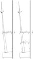
- FIG 1 shows a testing device for testing a rotor blade 1 of a wind turbine.
- the testing device is in an assembly stage in which several load frames spaced apart from one another in the longitudinal direction and load introduction means acting thereon are gradually arranged at previously determined positions on a rotor blade.
- the testing device comprises a clamping device 2, in which the complete rotor blade 1 is clamped at a clamping point 1', so that its longitudinal axis extends approximately horizontally, while a pivoting direction extends horizontally, orthogonally to the plane of the drawing. A direction of impact accordingly runs approximately vertically.
- An active load introduction means 5 is arranged on the rotor blade and is designed as a hydraulic, pneumatic or electric actuator.
- the actuator is connected by means of joints 11A, 11B to a load frame 4A fixed to the rotor blade and also to a floor 3 via an additional rod.
- the actuator acts as an active load introduction means in the direction of flapping of the rotor blade, i.e. essentially vertically, whereby at least when the rotor blade is made to vibrate, the actuator can deviate from the vertical thanks to the joints 11A, 11B and can continue to introduce load into the rotor blade .
- a further load frame 4B is arranged further outside on the rotor blade 1 and holds a fixed mass 15 as a passive load introduction means, by means of which the vibration behavior of the rotor blade 1 is influenced.
- the fixed mass 15 changes the bending moment acting on the rotor blade on the one hand and modifies the natural frequencies of the oscillating rotor blade 1 on the other.
- This means that a system natural frequency for a system that includes the rotor blade 1 and the passive load application means is modified in the pivoting direction and in the flapping direction compared to the natural frequency of the rotor blade 1 due to the passive load application means designed as a fixed mass 15 .
- the actuator can be operated in such a way that its load application frequency matches the system natural frequency in the impact direction in which the actuator acts. However, it can also be operated with a detuning of, for example, less than 1% compared to the natural frequency of the system, in order to act as a so-called actuator mass or actuator spring to act and introduce an additional load into the rot
- the Indian figure 1 The structure shown represents a possible starting structure for the testing device proposed here, which is expanded by additional elements in typical methods according to this application.
- the position of the load frame 4 and the configuration and arrangement of the active and passive load application means are selected in such a way that a predetermined desired bending moment distribution is achieved as well as possible.
- a second passive load introduction means which is designed as a spring 7 and also acts in the impact direction.
- the spring 7 is movably attached to the rotor blade 1 and the ground 3 by means of joints 11C, 11D. It sits between the active load application means 5 and the clamping point 1' and changes the bending moment distribution in this area.
- the natural frequency of the system for the impact direction is further changed by the spring 7, but the natural frequency of the system for the pivoting direction is hardly or not at all influenced. Only in the case of very large deflections in the pivoting direction can a movement in the pivoting direction be influenced by the spring 7 shown.
- Such a spring is therefore suitable for adapting the system natural frequency for only one selected direction.
- figure 3 shows a structure similar to that figure 2 , where in contrast to figure 2 a decoupled mass 6 acts on the second load frame 4B instead of the fixed mass 15 .
- the decoupled mass 6 is arranged at one end of a lever arm 9 which is mounted on a hinge 10 as a seesaw.
- the lever arm is connected to the second load frame 4B by means of a rod 8 and by means of joints 11E, 11F.
- the weight of the decoupled mass 6 therefore exerts a pressure on the rotor blade 1 from below due to the seesaw.
- the decoupled mass 6 again influences the acting bending moment and can be used to adapt the bending moment distribution to the desired bending moment distribution.
- FIG 4 shows a test device in which the rotor blade as in the Figures 1 to 3 is clamped.
- this testing device there are six load frames 4A-4F, to which active or passive load introduction means are respectively coupled.
- a distance between adjacent load frames is always at least 1 m.
- load introduction means are also shown, which are designed in such a way that they act in the pivoting direction but not in the direction of impact, as will be explained below.
- the figure shows a separate load frame for each load introduction means, it is also possible for several load introduction means to act on a single load frame.
- one or more of the load frames can each have a load introduction device that acts in the impact direction and a load introduction device that acts in the pivoting direction (see also figure 16 .
- at least two load frames will typically be at least required in order to be able to fasten the minimum number of load introduction devices considered in the procedure and to achieve the desired bending moment distribution well.
- an elastic element designed as a spring 7A is configured as a passive load introduction means in such a way that it acts in the flapping direction of the rotor blade 1 .
- the spring acts on the load frame 4A via a lever arm 9A pivotable about a hinge 10A and a vertical rod 8A connected to the lever arm and affects the bending moment distribution in the direction of impact.
- a spring 7B acts as a passive load introduction means.
- the spring 7B acts on one end of a lever arm 9B. At the other end of the lever arm 9B this sits on a hinge 10B. Above the hinge 10B there is additionally provided an angle bar 16A which extends upwards at right angles to the lever arm 9B.
- the angle beam is in turn connected to the load frame 4B by a horizontally extending rod 8B. That is, the passive load of the spring 7B is redirected by the device so that the bending moment distribution in the vicinity of the second load frame 4B is modified in the pivoting direction.
- an actuator 5A is arranged as an active load introduction means, as in FIGS Figures 1 to 3 is designed and accordingly acts in the impact direction.
- Another actuator 5B is arranged on a fourth load frame 4D acts in the pivoting direction. This is achieved analogously to the case of the load frame 4B, in that the further actuator 5B is connected to a lever arm 9C which is movably mounted on a hinge 10C. The lever arm is connected to the fourth load frame 4D via an angle beam 16B pointing upwards and a horizontal rod 8C, and the force introduced by the further actuator 5B is thus diverted in the pivoting direction.
- the decoupled mass acting on load frame 4E acts exactly as in the case of figure 3 in the direction of the blow.
- the decoupled mass 6B connected to the load frame 4F acts in the pivoting direction by, again analogous to the case of the load frame 4B or 4D, a lever arm on which it is placed, on a side opposite the mass 6B with an angle beam 16C and a rod 8E is equipped.
- the elastic elements are arranged closest to the clamping point, followed by active load application means and finally the decoupled masses located furthest to the outside.
- This configuration can be advantageous for producing bending moment distributions typical of rotor blades.
- the passive load application means are used to adapt the bending moment distributions in the pivoting and impact directions to the target bending moment distribution in the respective direction in such a way that the bending moment distribution during testing is no more than 10% or no more than 5% above the target bending moment distribution and this at the same time not fall below.
- the system natural frequencies for the rotor blade 1 are changed with the load introduction means arranged thereon.
- the direction of action of the rods 8B, 8C, 8E for the passive and active load application means in the pivoting direction is chosen such that in the rest state it coincides with the direction of pivoting movement at the load application point.
- the load application means can then act decoupled from the impact moment.
- this can mean that the pivoting and impact modes and their respective directions of movement for the system with the passive load introduction means arranged thereon are determined at the different sections on which the load frames are located, and the rods are arranged as described using the determined directions of movement. During the test, the rods are then deflected equally in both directions from the resting state.
- the natural frequencies of the system in the impact direction and in the pivoting direction are adjusted by the passive load application means in such a way that they do not deviate by more than 10% from the load application frequency in the respective direction.
- excitation is carried out precisely with the natural frequencies of the system, i.e. the load application frequencies correspond to the natural frequencies of the system in the respective direction. This further reduces the test duration and energy consumption.
- the load introduction frequencies are detuned compared to the system natural frequencies in the respective direction, i.e. a deviation of at most 10% or at most 5% or at most 2% or at most 1% compared to the system natural frequency is set. As a result, an additional load can be introduced into the rotor blade 1 .
- the actuators 5A, 5B of the active load introduction means are designed as hydraulic, pneumatic or electric actuators. In the present example, they are anchored externally, which means that the possible additional load introduction described can be advantageously achieved by detuning the excitation frequencies. However, it is also possible to design the active load application means as mass exciters, ie as actuators fixed to the rotor blade 1, which cyclically move a mass attached thereto.
- At least one of the passive load introduction means is usually designed as a decoupled mass or as an elastic element and connected to the floor or the wall. Furthermore, it is typical in the method or the test devices that at least one passive load introduction means for load introduction in the pivoting direction and at least one passive load introduction means for load introduction in the impact direction is set up.
- the rotor blade 1 may have a natural frequency of 0.7 Hz in the flapping direction and a natural frequency of 0.9 Hz in the pivoting direction.
- the load introduction can take place with the corresponding frequency ratio in resonance, ie the load introduction frequency can be chosen to be equal to the natural frequency of the system.
- the cycles can then be easily observed and counted.
- a frequency ratio of 1:1 for example, 3 million cycles can be carried out for each direction.
- a frequency ratio of 1:2 for example, 1 million
- a frequency ratio of 2:1 is therefore advantageous, for example, when twice as many cycles are provided in one direction for applying the desired load as in the other direction.
- the test stand has a control and/or regulation device for setting and maintaining the frequency ratio. This allows the leaf to perform movements corresponding to closed Lissajous figures throughout the test period.
- figure 5 shows a passive load introduction means, in which a spring 7 as an elastic element is connected to the floor 3 and an underside of a load frame 4 via joints 11A, 11B, so that a spring force acts by compression or expansion of the spring in the flapping direction of the rotor blade 1.
- figure 6 1 shows a passive load application means with a spring 7 as an elastic element, which is connected here to the underside of a lever arm 9 which is movably arranged by a hinge 10 and in turn is connected via a rod 8 to the underside of the load frame 4.
- the arrangement acts in the direction of impact.
- the force acting on the rotor blade 1 can be adjusted independently of the distance between the ground and the rotor blade 1.
- the length of the spring 7, its strength and the distance between hinge 10 and spring 7 and between spring 7 and rod 8 can be varied.
- the build up figure 6 can also be used analogously for an active load introduction means by replacing the spring 7 with an actuator.
- figure 7 shows an arrangement for passive load introduction, in which a lever arm 9 is fixed on an elastic element designed as a torsion spring 12 .
- the lever arm moves when the torsion spring 12 deforms and transmits a force caused by the torsion spring 12 via a rod 8 from below into the load frame 4 so that it acts in the flapping direction of the rotor blade 1 .
- the effect of the torsion spring 12 on the rotor blade 1 can be adjusted here by the length of the lever arm 9 .
- Figure 1 shows a passive load application means in which an elastic element is provided by horizontally supporting a deformable beam 13 at two opposite ends on hinges 10A, 10B so that it can flex in the middle.
- a rod 8 which extends vertically upwards and engages the load frame below to apply a flapwise force to the rotor blade 1 .
- the beam 13 is made from a fiber composite material that contains glass fibers and/or carbon fibers in order to be able to withstand the heavy loads during the rotor blade test 1 and to have the required elastic properties.
- the spring force acting through the beam can be modified by the distance between the two hinges 10A, 10B.
- Figure 12 shows an embodiment of an elastic element formed as a flexible beam 13 fixed on one side only.
- the beam is attached to a wall or elevation in such a way that it extends horizontally from its attachment and can be deflected up and down under elastic deformation.
- the beam 13 is connected to the underside of the load frame 4 via a rod 8, so that the forces resulting from the deformation of the beam 13 act in the flapping direction of the rotor blade.
- figure 10 shows a similar design of a passive load introduction means as the figure 9 , the beam at the end remote from the rod 8 being placed on two juxtaposed hinges 10A, 10B, rather than on a wall or elevation, which support the beam 13 so that the end with the rod 8 can further deform.
- figure 11 shows an arrangement similar to that figure 8 , where instead of the beam 13 a leaf spring 14 is supported at opposite ends on two hinges 10A, 10B so that its middle, which is connected via a rod 8 to the load frame 4, can deflect.
- the leaf spring 14 can be made of a fiber composite material with glass fibers and/or carbon fibers.
- the elastic elements can be provided with a pretension, so that a mean bending moment acting on the rotor blade 1 due to gravity is at least partially compensated.
- This can be necessary, for example, to achieve the specified setpoint bending moment distribution according to the invention, in order to avoid an overload in a deflection direction of the rotor blade 1 .
- it can also be used to set the mean bending moment as desired to a target mean bending moment. This setting can also be made in the pivoting direction.
- figure 12 shows an embodiment of a passive load application means as an externally anchored decoupled mass. It is the same design as in the Figures 3 and 4 , which acts in the direction of impact.
- the decoupled mass 6 acts both as an oscillating mass for the impact direction and as a compensating force directed counter to gravity in order to avoid an overload caused by gravity.
- figure 13 shows a passive load introduction means with a spring 7 as an elastic element, which acts in the pivoting direction.
- the spring is connected to a lever arm 9 mounted on a hinge 10 and initially acts on the lever arm, which moves around the hinge 10 .
- an angle beam 16 which extends upwards and on this in turn is a horizontal rod 8 which acts into the load frame 4 horizontally.
- the arrangement with angle beam 16 and rod 8 redirects the force so that the vertically extending spring acts horizontally.
- the configuration off figure 13 can be carried out without prestressing of the elastic element, but can also be carried out with prestressing in embodiments in which prestressing in the pivoting direction is desired.
- figure 14 shows an active load application means that acts in the pivoting direction of the rotor blade 1, ie horizontally.
- the arrangement for deflecting the effective direction is already, for example, from the figure 13 known arrangement with angle bar 16 and horizontal bar 8, wherein instead of the passive spring 7, an active actuator 5 is used.
- figure 15 shows a structure for a decoupled mass 6, which is intended to act as an oscillating mass in the pivoting direction.
- the effective direction is again adjusted by means of the angle bar 16 and rod 8.
- the decoupled mass 6 also causes a preload or medium load in the pivoting direction.
- figure 16 shows an example of a combination of a horizontally acting and a vertically acting load introduction means, both of which act on the same load frame 4. These are two passive load application devices.
- a decoupled mass 6 acts in the flapping direction and an elastic element acts in the pivoting direction.
- the elastic member for the pivoting direction is formed as a vertically extending beam 13 fixed to the floor 3 and acting on the load frame via a horizontal rod 8A.
- the embodiment illustrates how a load application means can be provided for each of the two directions on a single load frame.
- other types of load introduction means can also be combined with one another.
- each of the load introduction means from the Figures 5 to 12 with each of the load application means from the Figures 13 to 15 be combined in order to achieve a bending moment distribution that deviates, for example, at most 10% from the target bending moment distribution.
- the decoupled mass 6 causes a prestress in the direction of impact, while the beam 13 does not cause any prestress in the pivoting direction.
- FIG. 1 shows a passive load introduction means for the pivoting direction, which comprises two equal-sized decoupled masses 6A, 6B, which are seated at opposite ends of a lever arm mounted centrally on a hinge 10.
- FIG. A vertical angle beam 16 is provided directly above the hinge 10 and is connected to the load frame 4 by a horizontal bar 8 . Due to the decoupled masses arranged in this way, the load introduction means acts as an oscillating mass exclusively in the pivoting direction, with a preload or medium load in the pivoting direction being avoided due to the balancing positioning of the decoupled masses 6A, 6B. By shifting one or both masses 6A, 6B or by using masses 6A, 6B of different sizes, the effective oscillating mass and prestress or average load can be adjusted.
- An asymmetrically acting passive load application device for the impact direction includes two decoupled masses, which as in 17 are arranged at opposite ends of a beam 9 which sits centrally on a hinge 10.
- a rod 8B is connected to the underside of the blade 1 .
- the rod 8B is displaced with respect to the joint 10 to be moved up and down as the beam moves, which corresponds to an oscillating mass load on the rotor blade 1 in the flapping direction.
- figure 19 illustrates an optimization process with the help of which a test setup can be achieved and parameters for the subsequent test can be determined.
- Constants or secondary conditions K1-K5, which are specified and cannot be changed, as well as specific target variables Z1-Z4, which can be achieved as well as possible using the optimization, are included in the optimization process.
- design variables D1-D7 are then adjusted in order to arrive at a structure and an experimental procedure with which the target variables can be achieved as well as possible.
- the optimization process then results in a concrete arrangement of load frames and active and passive load introduction means arranged on them, for example the figure 4 structure shown.
- the load introduction frequencies are also determined, with which the test procedure is to be used for excitation. It may also be that the number of cycles is also determined in the optimization process.
- a natural frequency in the flapping direction can be 0.5 Hz and a natural frequency in the pivoting direction can be 1 Hz in the unprepared state.
- 1 million cycles are required in the impact direction and 3 million cycles in the pivoting direction in order to at least achieve the desired load.
- this would result in a test duration of 23.1 days for the impact direction and 34.7 days for the impact direction, which corresponds to a total test duration of 57.8 days.
- the natural frequencies can be converted into system natural frequencies. These can have a rational ratio of 1:1, say both are 0.75 Hz.
- the amplitude of the load application in the impact direction can be changed in such a way that the desired damage is also achieved in this direction after 3 million cycles.
- the test then takes place in both directions in parallel, is completed simultaneously for both directions and lasts a total of 46.3 days. This reduces the test duration by 20% compared to the conventional procedure.
- FIG 20 the bending moment vector components for a cross section of a rotor blade are plotted in the flapping direction M t and in the pivoting direction M s .
- M s acts about an s-axis and M t acts about a t-axis (see also figure 21 to define the axes in relation to the rotor blade).
- An ellipse L5 corresponds to the superposition of a uni-axial pivot test L4 and an impact test L3 in a bi-axial test at a frequency ratio of 1:1 and a phase angle of 90°.
- Gravity causes a mean bending moment in the direction of impact, which is marked with L2 and runs as a horizontal line in the illustration.
- the ellipse is correspondingly shifted along L2 by the influence of gravity.
- This probability cloud L7 reproduces moment vector paths that typically occur in the field.
- Such probability clouds are determined with the help of aeroservoelastic multi-body simulations, typically for different load cases occurring in the field.
- the probability cloud L7 therefore indicates an area in which the moment vector paths run under realistic conditions.
- the center of the ellipse L5 achieved in the test method described here can be achieved by static mean bending moments in the flapping and pivoting direction (vector L1), which are introduced with the decoupled masses or prestressed spring elements described in this document , now continue to move along the vector L1 towards a point L8, which represents a center of the probability cloud L7. This corresponds to the setting of the target mean bending moment.
- vector L1 static mean bending moments in the flapping and pivoting direction
- the effective direction of the gravitational vector L2 relative to the ellipse L5 can be influenced in such a way that it corresponds to the effective direction of L1.
- the ellipse can be rotated counterclockwise/clockwise by adjusting the phase angle by greater/less than 90°. If the panning and flapping amplitudes are scaled, it is possible to transform the ellipse L5 into the ellipse L6 and thus approximate the moment cloud L7 occurring in the field.
- the advantage of this method is a more realistic load on the rotor blade (closer to the most frequently occurring field conditions). Furthermore, the shift in the center of the ellipse changes an occurring stress ratio R, which can lead to a reduction in the test cycles if the target bending moment distribution is adjusted due to the changed target mean bending moment, so that a uniform target damage of the load-bearing areas along the areas of the blade to be tested occurs (See, for example, the publication Rosemeier et al. "Benefits of subcomponent over full-scale blade testing elaborated on a trailing-edge bond line design validation", Wind Energ. Sci., 3, 163-172, 2018, https://doi.org/10.5194/wes-3-163-2018 ).
- figure 21 shows a structure for a decoupled mass 6, which is intended to act as an oscillating mass in the pivoting direction of a pitched rotor blade.
- the direction of action is adjusted using the angle bar 16 and rod 8.
- the rod 8 is mounted at right angles to the angle beam 16.
- the lever arm 9 is mounted parallel to the ground, so that the effective direction of the gravitational acceleration of the mass 6 is also aligned perpendicular to the ground.
- the decoupled mass 6 causes a preload or medium load in the pivoting direction.
- the figure shows the deflected state.
- figure 21 shows the coordinate system around whose axes the vectors act, which are in figure 20 are shown.
- the rotor blade shown in the figure is pitched to accommodate the influence of the mean bending moment caused by gravity in the pan and flap directions.
- the rod 8 is arranged obliquely, so that its direction of action in the rest state shown runs in a direction of movement of a natural mode of the system in the pivoting direction.
- figure 22 shows an embodiment of the testing device that is set up for carrying out the method described, with a load frame 4 being provided and two active load introduction means, each of which acts on the load frame 4, with a first active load introduction means 5B being set up for load introduction in a pivoting direction of the rotor blade 1 and a second active load introduction means 5A for load introduction in the direction of flapping of the rotor blade 1 is set up.
- a passive load introduction means 13 available, which also acts on the load frame 4.
- the passive load introduction means 13 is designed as an elastic bar and acts in the pivoting direction.
- a passive load introduction means for the direction of impact can act on the same load frame 4 .
- a system natural frequency for the pivoting direction and/or for the impact direction can be changed by one passive load introduction means 13 .
- Cyclic load introduction is effected by means of the two active load introduction means 5A, 5B, with a load introduction frequency of the first active load introduction means 5B and a load introduction frequency of the second active load introduction means 5A being selected such that their ratio is rational. In a possible embodiment of the test bench or method, no further load frame is required.
Landscapes
- Engineering & Computer Science (AREA)
- Physics & Mathematics (AREA)
- General Physics & Mathematics (AREA)
- Aviation & Aerospace Engineering (AREA)
- Sustainable Energy (AREA)
- Sustainable Development (AREA)
- Life Sciences & Earth Sciences (AREA)
- Chemical & Material Sciences (AREA)
- Combustion & Propulsion (AREA)
- Mechanical Engineering (AREA)
- General Engineering & Computer Science (AREA)
- Investigating Strength Of Materials By Application Of Mechanical Stress (AREA)
- Turbine Rotor Nozzle Sealing (AREA)
- Packages (AREA)
Claims (15)
- Procédé pour contrôler une pale de rotor (1) d'une installation éolienne, dans lequel une distribution de moment de flexion cible est définie, comprenant au moins les étapes consistant à :- serrer la pale de rotor (1) dans un dispositif de serrage (2) de sorte qu'un axe longitudinal de la pale de rotor (1) s'étend depuis un point de serrage (1') de la pale de rotor,- fixer un ou plusieurs cadres de charge (4) à la pale de rotor,- fournir au moins deux moyens actifs d'application de charge, qui agissent chacun sur un des cadre de charge (4), dans lequel un premier (5B) des au moins deux moyens actifs d'application de charge est conçu pour une application de charge dans une direction de pivotement de la pale de rotor (1) et un second (5A) des au moins deux moyens actifs d'application de charge est conçu pour une application de charge dans une direction de battement de la pale de rotor (1),- fournir au moins deux moyens passifs d'application de charge qui agissent chacun sur un des cadres de charge (4), dans lequel les deux moyens passifs d'application de charge sont conçus de manière à agir uniquement dans une direction,dans lequel au moins un des au moins deux moyens passifs d'application de charge est fourni pour régler la fréquence propre du système dans la direction de battement et au moins un des au moins deux moyens passifs d'application de charge est fourni pour régler la fréquence propre du système dans la direction de pivotement,dans lequel au moins un des au moins deux moyens passifs d'application de charge est réalisé sous la forme d'un élément élastique ou d'une masse découplée (6) qui est montée sur une bascule,dans lequel, pour un système qui comprend la pale de rotor et les au moins deux moyens passifs d'application de charge, une fréquence propre du système pour la direction de pivotement et pour la direction de battement est modifiée par les au moins deux moyens passifs d'application de charge,- appliquer une charge de manière cyclique par l'intermédiaire des au moins deux moyens actifs d'application de charge, dans lequel une fréquence d'application de charge fSchwenk du premier moyen actif d'application de charge (5B) et une fréquence d'application de charge fschlag du second moyen actif d'application de charge (5A) sont sélectionnées de manière à ce que leur rapport soit rationnel, de sorte que fschlag:fschwenk=n1:n2, dans lequel n1 et n2 sont des nombres naturels et n1 et n2 ne sont chacun pas supérieurs à 5, et dans lequelles cadres de charge (4) et les au moins deux moyens actifs d'application de charge et les au moins deux moyens passifs d'application de charge sont agencés dans des positions prédéterminées, qui sont choisies de telle sorte qu'une distribution de moment de flexion appliquée lors d'une application de charge de manière cyclique ne soit pas inférieure à la distribution de moment de flexion cible et ne la dépasse pas de plus de 20 %, de préférence pas de plus de 15 %, et de préférence pas de plus de 10 %.
- Procédé selon la revendication 1, dans lequel les au moins deux moyens passifs d'application de charge sont agencés de telle manière que la fréquence propre du système pour la direction de battement correspond à la fréquence d'application de charge dans la direction de battement ou, pour introduire une charge supplémentaire, ne s'écarte pas de plus de 10 % de la fréquence propre du système dans la direction de battement et/ou dans lequel les au moins deux moyens passifs d'application de charge sont agencés de telle sorte que la fréquence propre du système dans la direction de pivotement correspond à la fréquence d'application de charge dans la direction de pivotement ou, pour introduire une charge supplémentaire, ne s'écarte pas de plus de 10 % de la fréquence propre du système dans la direction de pivotement.
- Procédé selon l'une quelconque des revendications précédentes, dans lequel les au moins deux moyens actifs d'application de charge sont commandés ou régulés pour établir et maintenir le rapport entre la fréquence d'application de charge du premier moyen actif d'application de charge (5B) et la fréquence d'application de charge du second moyen actif d'application de charge (5A).
- Procédé selon l'une quelconque des revendications précédentes, dans lequel la pale de rotor (1) est serrée de telle sorte que l'axe longitudinal de la pale de rotor (1) s'étend essentiellement horizontalement et la direction de pivotement est orientée horizontalement.
- Procédé selon l'une quelconque des revendications précédentes, dans lequel les au moins deux moyens actifs d'application de charge et/ou au moins l'un des au moins deux moyens passifs d'application de charge sont ancrés extérieurement.
- Procédé selon l'une quelconque des revendications précédentes, dans lequel le rapport entre la fréquence d'application de charge du premier moyen d'application de charge (5B) et la fréquence d'application de charge du second moyen d'application de charge est de 1:1, 2:1 ou 1:2.
- Procédé selon l'une quelconque des revendications précédentes, dans lequel une distribution de tracés vectoriels de moment survenant dans le champ est déterminée, de préférence au moyen d'une simulation multicorps aéro-servoélastique, et un moment de flexion moyen cible par les moyens passifs d'application de charge, de préférence par les masses découplées (6) et/ou par une précontrainte des éléments élastiques, est réglé de manière à ce qu'un point central des tracés vectoriels de moment générés au moyen des moyens actifs d'application de charge se situe à l'intérieur de la distribution des tracés vectoriels de moment se produisant dans le champ, dans lequel en particulier les trajets vectoriels de moment générés par les moyens actifs d'application de charge sont adaptés à un contour de la distribution des tracés vectoriels de moment survenant dans le champ, la pale de rotor (1) étant mise en marche dans le sens horaire ou antihoraire autour de son axe longitudinal.
- Procédé selon la revendication 7, dans lequel les tracés vectoriels de moment générés par les moyens actifs d'application de charge sont adaptés à un contour de la distribution des tracés vectoriels de moment se produisant dans le champ en ajustant un angle de phase entre l'application de charge dans la direction de pivotement et l'application de charge dans la direction de battement.
- Procédé selon l'une quelconque des revendications précédentes, dans lequel le rapport entre les fréquences d'application de charge est de 1:1 et un angle de phase entre une application de charge dans la direction de pivotement et une application de charge dans la direction de battement est compris entre 0° et 180°, de préférence entre 45° et 135°, de manière particulièrement préférée est de 90°.
- Procédé selon l'une quelconque des revendications 1 à 9, dans lequel le rapport entre les fréquences d'application de charge est de 1:2 ou 2:1 et un angle de phase entre l'application de charge dans la direction de pivotement et l'application de charge dans la direction de battement est de 0° ou 180°.
- Procédé selon l'une quelconque des revendications précédentes, dans lequel une distance minimum entre des cadres de charge adjacents est de 1 m.
- Dispositif de contrôle pour contrôler une pale de rotor (1) selon un procédé selon l'une quelconque des revendications précédentes, comprenant- la pale de rotor (1),- un dispositif de serrage (2) pour serrer la pale de rotor (1) au niveau d'un point de serrage (1') de la pale de rotor (1), de sorte qu'un axe longitudinal de la pale de rotor (1) s'étend sensiblement horizontalement à partir du point de serrage (1'),un ou plusieurs cadres de charge (4) destinés à être fixés à la pale de rotor (1),au moins deux moyens actifs d'application de charge fixés chacun à l'un des cadres de charge (4),au moins deux moyens passifs d'application de charge, qui sont fixés chacun à l'un des cadres de charge (4),dans lequel les deux moyens passifs d'application de charge sont conçus de telle sorte qu'ils n'agissent que dans une direction,dans lequel au moins un des au moins deux moyens passifs d'application de charge est configuré pour régler la fréquence propre du système dans la direction de battement et au moins un des au moins deux moyens passifs d'application de charge est configuré pour régler la fréquence propre du système dans la direction de pivotement,dans lequelau moins un des au moins deux moyens actifs d'application de charge est configuré pour une application de charge dans une direction de pivotement dans la pale de rotor (1) et au moins un des au moins deux moyens actifs d'application de charge est configuré pour une application de charge dans une direction de battement dans la pale de rotor (1),et dans lequel au moins un des au moins deux moyens passifs d'application de charge est ancré extérieurement et comprend un élément élastique et/ou une masse découplée qui est montée sur une bascule et est configuré pour ajuster une fréquence propre du système dans la direction de pivotement ou dans la direction de battement pour un système qui comprend la pale de rotor et les au moins deux moyens passifs d'application de charge,contenant en outre un dispositif de réglage qui est configuré pour régler une fréquence d'application de charge fSchwenk du premier moyen actif d'application de charge et une fréquence d'application de charge fschlag du second moyen actif d'application de charge, de sorte qu'un rapport entre ces deux fréquences d'application de charge soit rationnel, tel que fschlag:fschwenk=n1:n2, dans lequel n1 et n2 sont des nombres naturels et n1 et n2 ne sont chacun pas supérieurs à 5,dans lequel les cadres de charge (4) et les au moins deux moyens actifs d'application de charge et les au moins deux moyens passifs d'application de charge sont agencés dans des positions prédéterminées, qui sont choisies de telle sorte qu'une distribution de moment de flexion appliquée lors d'une application de charge de manière cyclique ne soit pas inférieure à la distribution de moment de flexion cible et ne la dépasse pas de plus de 20 %, de préférence pas de plus de 15 %, et de préférence pas de plus de 10 %.
- Dispositif de contrôle selon la revendication 12, dans lequel les moyens actifs d'application de charge sont réalisés sous la forme d'actionneurs hydrauliques, pneumatiques ou électriques et sont de préférence ancrés extérieurement.
- Dispositif de contrôle selon l'une quelconque des revendications 12 ou 13, dans lequel l'élément élastique est réalisé sous la forme d'un ressort ou d'un ressort de torsion ou d'un ressort à barre ou à lame et est de préférence ancré extérieurement.
- Dispositif de contrôle selon l'une quelconque des revendications 12 à 14, dans lequel l'élément élastique comprend un matériau composite fibreux, de préférence avec des fibres de verre et/ou des fibres de carbone.
Applications Claiming Priority (2)
| Application Number | Priority Date | Filing Date | Title |
|---|---|---|---|
| DE102018218515.8A DE102018218515A1 (de) | 2018-10-29 | 2018-10-29 | Verfahren und Prüfvorrichtung zum Prüfen von Rotorblättern |
| PCT/EP2019/079073 WO2020089038A1 (fr) | 2018-10-29 | 2019-10-24 | Procédé et dispositif d'essai pour soumettre à essai des pales de rotor |
Publications (2)
| Publication Number | Publication Date |
|---|---|
| EP3874248A1 EP3874248A1 (fr) | 2021-09-08 |
| EP3874248B1 true EP3874248B1 (fr) | 2023-03-08 |
Family
ID=68342932
Family Applications (1)
| Application Number | Title | Priority Date | Filing Date |
|---|---|---|---|
| EP19794148.7A Active EP3874248B1 (fr) | 2018-10-29 | 2019-10-24 | Procédé et dispositif d'essai pour soumettre à essai des pales de rotor |
Country Status (8)
| Country | Link |
|---|---|
| US (1) | US11885299B2 (fr) |
| EP (1) | EP3874248B1 (fr) |
| DE (1) | DE102018218515A1 (fr) |
| DK (1) | DK3874248T5 (fr) |
| ES (1) | ES2945577T3 (fr) |
| PL (1) | PL3874248T3 (fr) |
| PT (1) | PT3874248T (fr) |
| WO (1) | WO2020089038A1 (fr) |
Cited By (1)
| Publication number | Priority date | Publication date | Assignee | Title |
|---|---|---|---|---|
| EP4143526B1 (fr) | 2020-04-29 | 2024-04-17 | LM Wind Power A/S | Dispositif appliquant une force sur une pale d'éolienne et procédé de test de fatigue de la pale |
Families Citing this family (13)
| Publication number | Priority date | Publication date | Assignee | Title |
|---|---|---|---|---|
| WO2020208925A1 (fr) * | 2019-04-12 | 2020-10-15 | 株式会社Ihi | Gabarit pour essai de vibration d'une pale de rotor |
| ES2902804T3 (es) * | 2019-04-23 | 2022-03-29 | Siemens Gamesa Renewable Energy As | Dispositivo excitador y método para ensayos de fatiga de un aspa de una turbina eólica |
| DE102021201751B4 (de) | 2021-02-24 | 2025-12-24 | Fraunhofer-Gesellschaft zur Förderung der angewandten Forschung eingetragener Verein | Verfahren zur sequenziellen ermüdungsprüfung |
| DE102022104846A1 (de) | 2022-03-01 | 2023-09-07 | Wobben Properties Gmbh | Verfahren und Testvorrichtung zum zeitgleichen Testen von zwei Rotorblättern und/oder zwei Rotorblattsegmenten für eine Windenergieanlage |
| EP4537070A1 (fr) * | 2022-06-13 | 2025-04-16 | Nordex Energy SE & Co. KG | Dispositif de mesure de fréquence propre et système de détermination de fréquence propre d'une pale de rotor d'éolienne |
| CN117780566A (zh) * | 2022-09-21 | 2024-03-29 | 金风科技股份有限公司 | 载荷加载装置和用于风力发电机的载荷加载试验台 |
| DE102022211982A1 (de) | 2022-11-11 | 2024-05-16 | Fraunhofer-Gesellschaft zur Förderung der angewandten Forschung eingetragener Verein | Vorrichtung und Verfahren zum Prüfen von länglichen Prüfkörpern |
| CN115759745B (zh) * | 2022-11-17 | 2025-10-28 | 北京天泽智云科技有限公司 | 一种叶片结构损伤故障诊断方法、系统及电子设备 |
| EP4702332A2 (fr) * | 2023-04-28 | 2026-03-04 | Vestas Wind Systems A/S | Test d'échantillon de pale d'éolienne |
| DE102024204159B4 (de) * | 2024-05-03 | 2025-12-31 | Fraunhofer-Gesellschaft zur Förderung der angewandten Forschung eingetragener Verein | Prüfvorrichtung zur mechanischen Prüfung eines balkenförmigen Prüflings |
| CN118532301B (zh) * | 2024-05-14 | 2025-01-28 | 中国石油大学(华东) | 一种基于质量关系的风电叶片缩比准则构建与测试方法 |
| DE102024115205A1 (de) * | 2024-05-31 | 2025-12-04 | Fraunhofer-Gesellschaft zur Förderung der angewandten Forschung eingetragener Verein | System und Verfahren zum kombinierten Testen eines Rotorblatts einer Windenergieanlage und eines Rotorblattlagers einer Windenergieanlage |
| EP4695594A4 (fr) | 2024-07-03 | 2026-04-22 | Envision Energy Co Ltd | Test de fatigue biaxiale à fréquence unique pour pales d'éolienne |
Family Cites Families (7)
| Publication number | Priority date | Publication date | Assignee | Title |
|---|---|---|---|---|
| AU2002320247A1 (en) * | 2002-07-03 | 2004-01-23 | Midwest Research Institute | Resonance test system |
| WO2009135136A2 (fr) * | 2008-05-02 | 2009-11-05 | Alliance For Sustainable Energy, Llc | Système d’essai d’excitation de base au moyen d’éléments de type ressort pour monter de manière pivotante des pales d’éolienne |
| US8578753B2 (en) * | 2009-12-17 | 2013-11-12 | Sikorsky Aircraft Corporation | Impact test fixture with simulated centrifugal force |
| WO2011091081A1 (fr) * | 2010-01-19 | 2011-07-28 | Modular Wind Energy, Inc. | Systèmes et procédés pour effectuer des tests structurels sur des aubes d'éoliennes |
| DE102012025649A1 (de) * | 2012-12-05 | 2015-08-06 | Industrieanlagen-Betriebsgesellschaft Mbh | Prüfstand für ein Rotorblatt, Anordnung mit einem derartigen Prüfstand und Verfahren zum Betreiben eines derartigen Prüfstands |
| DE102012111838B4 (de) * | 2012-12-05 | 2014-12-04 | Industrieanlagen-Betriebsgesellschaft Mbh | Prüfstand für ein Rotorblatt, Anordnung mit einem derartigen Prüfstand und Verfahren zum Betreiben eines derartigen Prüfstands |
| CN107110736B (zh) * | 2014-09-26 | 2020-02-04 | 维斯塔斯风力系统有限公司 | 风轮机叶片的疲劳试验 |
-
2018
- 2018-10-29 DE DE102018218515.8A patent/DE102018218515A1/de not_active Ceased
-
2019
- 2019-10-24 US US17/288,623 patent/US11885299B2/en active Active
- 2019-10-24 EP EP19794148.7A patent/EP3874248B1/fr active Active
- 2019-10-24 ES ES19794148T patent/ES2945577T3/es active Active
- 2019-10-24 DK DK19794148.7T patent/DK3874248T5/da active
- 2019-10-24 WO PCT/EP2019/079073 patent/WO2020089038A1/fr not_active Ceased
- 2019-10-24 PL PL19794148.7T patent/PL3874248T3/pl unknown
- 2019-10-24 PT PT197941487T patent/PT3874248T/pt unknown
Cited By (1)
| Publication number | Priority date | Publication date | Assignee | Title |
|---|---|---|---|---|
| EP4143526B1 (fr) | 2020-04-29 | 2024-04-17 | LM Wind Power A/S | Dispositif appliquant une force sur une pale d'éolienne et procédé de test de fatigue de la pale |
Also Published As
| Publication number | Publication date |
|---|---|
| DK3874248T5 (da) | 2023-05-30 |
| US20220010780A1 (en) | 2022-01-13 |
| ES2945577T3 (es) | 2023-07-04 |
| WO2020089038A1 (fr) | 2020-05-07 |
| DE102018218515A1 (de) | 2020-04-30 |
| PL3874248T3 (pl) | 2023-10-09 |
| US11885299B2 (en) | 2024-01-30 |
| EP3874248A1 (fr) | 2021-09-08 |
| PT3874248T (pt) | 2023-05-18 |
| DK3874248T3 (da) | 2023-05-22 |
Similar Documents
| Publication | Publication Date | Title |
|---|---|---|
| EP3874248B1 (fr) | Procédé et dispositif d'essai pour soumettre à essai des pales de rotor | |
| EP2741068B1 (fr) | Banc d'essai pour une pale de rotor, dispositif doté d'un tel banc d'essai et procédé de fonctionnement d'un tel banc d'essai | |
| EP2741069B1 (fr) | Banc d'essai pour une pale de rotor ou un segment de pale de rotor, agencement doté d'un tel banc d'essai et procédé d'essai | |
| EP1524513A2 (fr) | Dispositif de poussée de pression pour l'introduction de fortes charges de pression dans une partie d'avion courbée | |
| WO2013143638A1 (fr) | Dispositif de contrôle et dispositif à masses oscillantes pour une pale de rotor d'une éolienne | |
| EP2522850B1 (fr) | Réducteur de vibrations pour tour et tour dotée d'un réducteur de vibrations pour tour | |
| DE102020200822A1 (de) | Mechanische Prüfvorrichtung und Verfahren zum Prüfen von balkenförmigen Prüflingen, insbesondere Rotorblättern von Windenergieanlagen | |
| EP3610172A1 (fr) | Amortissement des vibrations d'une tour de centrale éolienne | |
| DE202011001901U1 (de) | Vorrichtung zur Schwingungsanregung von Rotorblättern im Rahmen von Schwingungstests | |
| DE102010021867A1 (de) | Kraftgenerator zur Anbringung an einer Struktur | |
| DE102021201751A1 (de) | Verfahren zur sequenziellen ermüdungsprüfung | |
| DE2913681A1 (de) | Vibrationspruefgeraet | |
| DE102012025649A1 (de) | Prüfstand für ein Rotorblatt, Anordnung mit einem derartigen Prüfstand und Verfahren zum Betreiben eines derartigen Prüfstands | |
| EP1322873B1 (fr) | Actionneur d'extension piezo-electrique | |
| EP3704461B1 (fr) | Procédé pour déterminer des propriétés élastoplastiques et le comportement d'échec d'un échantillon d'essai | |
| EP3803313B1 (fr) | Cadre porte-charge, système de banc d'essai et procédé d'utilisation du cadre porte-charge | |
| DE102012108304A1 (de) | Prüfverfahren zur Prüfung der Belastbarkeit eines Werkstoffprüflings und Prüfeinrichtung | |
| EP4239307B1 (fr) | Procédé et dispositif de test pour tester simultanément deux pales de rotor et/ou deux segments de pale de rotor pour une éolienne | |
| WO2015043879A1 (fr) | Compresseur à engrenage et procédé de montage | |
| EP3722772A1 (fr) | Banc d'essai et procédure d'essai pour une pale de rotor à énergie éolienne | |
| EP3415890B1 (fr) | Banc d'essai pour un raccord d'articulation de pas | |
| EP3771846A1 (fr) | Système de couplage mécanique destiné au couplage isolant contre les vibrations de deux systèmes partiels | |
| EP4616166A1 (fr) | Dispositif et procédé de test d'éprouvettes allongées | |
| DE102024204159B4 (de) | Prüfvorrichtung zur mechanischen Prüfung eines balkenförmigen Prüflings | |
| DE102024115205A1 (de) | System und Verfahren zum kombinierten Testen eines Rotorblatts einer Windenergieanlage und eines Rotorblattlagers einer Windenergieanlage |
Legal Events
| Date | Code | Title | Description |
|---|---|---|---|
| STAA | Information on the status of an ep patent application or granted ep patent |
Free format text: STATUS: UNKNOWN |
|
| STAA | Information on the status of an ep patent application or granted ep patent |
Free format text: STATUS: THE INTERNATIONAL PUBLICATION HAS BEEN MADE |
|
| PUAI | Public reference made under article 153(3) epc to a published international application that has entered the european phase |
Free format text: ORIGINAL CODE: 0009012 |
|
| STAA | Information on the status of an ep patent application or granted ep patent |
Free format text: STATUS: REQUEST FOR EXAMINATION WAS MADE |
|
| 17P | Request for examination filed |
Effective date: 20210526 |
|
| AK | Designated contracting states |
Kind code of ref document: A1 Designated state(s): AL AT BE BG CH CY CZ DE DK EE ES FI FR GB GR HR HU IE IS IT LI LT LU LV MC MK MT NL NO PL PT RO RS SE SI SK SM TR |
|
| DAV | Request for validation of the european patent (deleted) | ||
| DAX | Request for extension of the european patent (deleted) | ||
| RAP3 | Party data changed (applicant data changed or rights of an application transferred) |
Owner name: FRAUNHOFER-GESELLSCHAFT ZUR FOERDERUNG DER ANGEWANDTEN FORSCHUNG E.V. |
|
| GRAP | Despatch of communication of intention to grant a patent |
Free format text: ORIGINAL CODE: EPIDOSNIGR1 |
|
| STAA | Information on the status of an ep patent application or granted ep patent |
Free format text: STATUS: GRANT OF PATENT IS INTENDED |
|
| INTG | Intention to grant announced |
Effective date: 20220929 |
|
| GRAS | Grant fee paid |
Free format text: ORIGINAL CODE: EPIDOSNIGR3 |
|
| GRAA | (expected) grant |
Free format text: ORIGINAL CODE: 0009210 |
|
| STAA | Information on the status of an ep patent application or granted ep patent |
Free format text: STATUS: THE PATENT HAS BEEN GRANTED |
|
| AK | Designated contracting states |
Kind code of ref document: B1 Designated state(s): AL AT BE BG CH CY CZ DE DK EE ES FI FR GB GR HR HU IE IS IT LI LT LU LV MC MK MT NL NO PL PT RO RS SE SI SK SM TR |
|
| REG | Reference to a national code |
Ref country code: CH Ref legal event code: EP Ref country code: AT Ref legal event code: REF Ref document number: 1552883 Country of ref document: AT Kind code of ref document: T Effective date: 20230315 |
|
| REG | Reference to a national code |
Ref country code: DE Ref legal event code: R096 Ref document number: 502019007180 Country of ref document: DE |
|
| REG | Reference to a national code |
Ref country code: IE Ref legal event code: FG4D Free format text: LANGUAGE OF EP DOCUMENT: GERMAN |
|
| REG | Reference to a national code |
Ref country code: NL Ref legal event code: FP |
|
| REG | Reference to a national code |
Ref country code: PT Ref legal event code: SC4A Ref document number: 3874248 Country of ref document: PT Date of ref document: 20230518 Kind code of ref document: T Free format text: AVAILABILITY OF NATIONAL TRANSLATION Effective date: 20230515 |
|
| REG | Reference to a national code |
Ref country code: DK Ref legal event code: T3 Effective date: 20230517 |
|
| REG | Reference to a national code |
Ref country code: DK Ref legal event code: T5 Effective date: 20230525 |
|
| REG | Reference to a national code |
Ref country code: SE Ref legal event code: TRGR |
|
| REG | Reference to a national code |
Ref country code: NO Ref legal event code: T2 Effective date: 20230308 Ref country code: LT Ref legal event code: MG9D |
|
| P01 | Opt-out of the competence of the unified patent court (upc) registered |
Effective date: 20230524 |
|
| REG | Reference to a national code |
Ref country code: ES Ref legal event code: FG2A Ref document number: 2945577 Country of ref document: ES Kind code of ref document: T3 Effective date: 20230704 |
|
| REG | Reference to a national code |
Ref country code: GR Ref legal event code: EP Ref document number: 20230400824 Country of ref document: GR Effective date: 20230710 |
|
| PG25 | Lapsed in a contracting state [announced via postgrant information from national office to epo] |
Ref country code: RS Free format text: LAPSE BECAUSE OF FAILURE TO SUBMIT A TRANSLATION OF THE DESCRIPTION OR TO PAY THE FEE WITHIN THE PRESCRIBED TIME-LIMIT Effective date: 20230308 Ref country code: LV Free format text: LAPSE BECAUSE OF FAILURE TO SUBMIT A TRANSLATION OF THE DESCRIPTION OR TO PAY THE FEE WITHIN THE PRESCRIBED TIME-LIMIT Effective date: 20230308 Ref country code: LT Free format text: LAPSE BECAUSE OF FAILURE TO SUBMIT A TRANSLATION OF THE DESCRIPTION OR TO PAY THE FEE WITHIN THE PRESCRIBED TIME-LIMIT Effective date: 20230308 Ref country code: HR Free format text: LAPSE BECAUSE OF FAILURE TO SUBMIT A TRANSLATION OF THE DESCRIPTION OR TO PAY THE FEE WITHIN THE PRESCRIBED TIME-LIMIT Effective date: 20230308 |
|
| PG25 | Lapsed in a contracting state [announced via postgrant information from national office to epo] |
Ref country code: FI Free format text: LAPSE BECAUSE OF FAILURE TO SUBMIT A TRANSLATION OF THE DESCRIPTION OR TO PAY THE FEE WITHIN THE PRESCRIBED TIME-LIMIT Effective date: 20230308 |
|
| PG25 | Lapsed in a contracting state [announced via postgrant information from national office to epo] |
Ref country code: SM Free format text: LAPSE BECAUSE OF FAILURE TO SUBMIT A TRANSLATION OF THE DESCRIPTION OR TO PAY THE FEE WITHIN THE PRESCRIBED TIME-LIMIT Effective date: 20230308 Ref country code: RO Free format text: LAPSE BECAUSE OF FAILURE TO SUBMIT A TRANSLATION OF THE DESCRIPTION OR TO PAY THE FEE WITHIN THE PRESCRIBED TIME-LIMIT Effective date: 20230308 Ref country code: EE Free format text: LAPSE BECAUSE OF FAILURE TO SUBMIT A TRANSLATION OF THE DESCRIPTION OR TO PAY THE FEE WITHIN THE PRESCRIBED TIME-LIMIT Effective date: 20230308 Ref country code: CZ Free format text: LAPSE BECAUSE OF FAILURE TO SUBMIT A TRANSLATION OF THE DESCRIPTION OR TO PAY THE FEE WITHIN THE PRESCRIBED TIME-LIMIT Effective date: 20230308 |
|
| PG25 | Lapsed in a contracting state [announced via postgrant information from national office to epo] |
Ref country code: SK Free format text: LAPSE BECAUSE OF FAILURE TO SUBMIT A TRANSLATION OF THE DESCRIPTION OR TO PAY THE FEE WITHIN THE PRESCRIBED TIME-LIMIT Effective date: 20230308 Ref country code: IS Free format text: LAPSE BECAUSE OF FAILURE TO SUBMIT A TRANSLATION OF THE DESCRIPTION OR TO PAY THE FEE WITHIN THE PRESCRIBED TIME-LIMIT Effective date: 20230708 |
|
| REG | Reference to a national code |
Ref country code: DE Ref legal event code: R097 Ref document number: 502019007180 Country of ref document: DE |
|
| PLBE | No opposition filed within time limit |
Free format text: ORIGINAL CODE: 0009261 |
|
| STAA | Information on the status of an ep patent application or granted ep patent |
Free format text: STATUS: NO OPPOSITION FILED WITHIN TIME LIMIT |
|
| PG25 | Lapsed in a contracting state [announced via postgrant information from national office to epo] |
Ref country code: SI Free format text: LAPSE BECAUSE OF FAILURE TO SUBMIT A TRANSLATION OF THE DESCRIPTION OR TO PAY THE FEE WITHIN THE PRESCRIBED TIME-LIMIT Effective date: 20230308 |
|
| 26N | No opposition filed |
Effective date: 20231211 |
|
| PG25 | Lapsed in a contracting state [announced via postgrant information from national office to epo] |
Ref country code: MC Free format text: LAPSE BECAUSE OF FAILURE TO SUBMIT A TRANSLATION OF THE DESCRIPTION OR TO PAY THE FEE WITHIN THE PRESCRIBED TIME-LIMIT Effective date: 20230308 |
|
| REG | Reference to a national code |
Ref country code: CH Ref legal event code: PL |
|
| REG | Reference to a national code |
Ref country code: BE Ref legal event code: MM Effective date: 20231031 |
|
| PG25 | Lapsed in a contracting state [announced via postgrant information from national office to epo] |
Ref country code: LU Free format text: LAPSE BECAUSE OF NON-PAYMENT OF DUE FEES Effective date: 20231024 |
|
| PG25 | Lapsed in a contracting state [announced via postgrant information from national office to epo] |
Ref country code: LU Free format text: LAPSE BECAUSE OF NON-PAYMENT OF DUE FEES Effective date: 20231024 |
|
| PG25 | Lapsed in a contracting state [announced via postgrant information from national office to epo] |
Ref country code: CH Free format text: LAPSE BECAUSE OF NON-PAYMENT OF DUE FEES Effective date: 20231031 |
|
| PG25 | Lapsed in a contracting state [announced via postgrant information from national office to epo] |
Ref country code: CH Free format text: LAPSE BECAUSE OF NON-PAYMENT OF DUE FEES Effective date: 20231031 |
|
| PG25 | Lapsed in a contracting state [announced via postgrant information from national office to epo] |
Ref country code: BE Free format text: LAPSE BECAUSE OF NON-PAYMENT OF DUE FEES Effective date: 20231031 |
|
| PG25 | Lapsed in a contracting state [announced via postgrant information from national office to epo] |
Ref country code: IE Free format text: LAPSE BECAUSE OF NON-PAYMENT OF DUE FEES Effective date: 20231024 |
|
| PG25 | Lapsed in a contracting state [announced via postgrant information from national office to epo] |
Ref country code: IE Free format text: LAPSE BECAUSE OF NON-PAYMENT OF DUE FEES Effective date: 20231024 |
|
| PG25 | Lapsed in a contracting state [announced via postgrant information from national office to epo] |
Ref country code: BG Free format text: LAPSE BECAUSE OF FAILURE TO SUBMIT A TRANSLATION OF THE DESCRIPTION OR TO PAY THE FEE WITHIN THE PRESCRIBED TIME-LIMIT Effective date: 20230308 |
|
| PG25 | Lapsed in a contracting state [announced via postgrant information from national office to epo] |
Ref country code: BG Free format text: LAPSE BECAUSE OF FAILURE TO SUBMIT A TRANSLATION OF THE DESCRIPTION OR TO PAY THE FEE WITHIN THE PRESCRIBED TIME-LIMIT Effective date: 20230308 |
|
| PG25 | Lapsed in a contracting state [announced via postgrant information from national office to epo] |
Ref country code: CY Free format text: LAPSE BECAUSE OF FAILURE TO SUBMIT A TRANSLATION OF THE DESCRIPTION OR TO PAY THE FEE WITHIN THE PRESCRIBED TIME-LIMIT; INVALID AB INITIO Effective date: 20191024 |
|
| PG25 | Lapsed in a contracting state [announced via postgrant information from national office to epo] |
Ref country code: HU Free format text: LAPSE BECAUSE OF FAILURE TO SUBMIT A TRANSLATION OF THE DESCRIPTION OR TO PAY THE FEE WITHIN THE PRESCRIBED TIME-LIMIT; INVALID AB INITIO Effective date: 20191024 |
|
| PGFP | Annual fee paid to national office [announced via postgrant information from national office to epo] |
Ref country code: NL Payment date: 20251023 Year of fee payment: 7 |
|
| PGFP | Annual fee paid to national office [announced via postgrant information from national office to epo] |
Ref country code: PT Payment date: 20251014 Year of fee payment: 7 |
|
| PG25 | Lapsed in a contracting state [announced via postgrant information from national office to epo] |
Ref country code: TR Free format text: LAPSE BECAUSE OF FAILURE TO SUBMIT A TRANSLATION OF THE DESCRIPTION OR TO PAY THE FEE WITHIN THE PRESCRIBED TIME-LIMIT Effective date: 20230308 |
|
| REG | Reference to a national code |
Ref country code: AT Ref legal event code: MM01 Ref document number: 1552883 Country of ref document: AT Kind code of ref document: T Effective date: 20241024 |
|
| PGFP | Annual fee paid to national office [announced via postgrant information from national office to epo] |
Ref country code: DE Payment date: 20251020 Year of fee payment: 7 |
|
| PGFP | Annual fee paid to national office [announced via postgrant information from national office to epo] |
Ref country code: GB Payment date: 20251024 Year of fee payment: 7 |
|
| PGFP | Annual fee paid to national office [announced via postgrant information from national office to epo] |
Ref country code: NO Payment date: 20251022 Year of fee payment: 7 |
|
| PG25 | Lapsed in a contracting state [announced via postgrant information from national office to epo] |
Ref country code: AT Free format text: LAPSE BECAUSE OF NON-PAYMENT OF DUE FEES Effective date: 20241024 |
|
| PGFP | Annual fee paid to national office [announced via postgrant information from national office to epo] |
Ref country code: DK Payment date: 20251023 Year of fee payment: 7 Ref country code: IT Payment date: 20251031 Year of fee payment: 7 |
|
| PGFP | Annual fee paid to national office [announced via postgrant information from national office to epo] |
Ref country code: FR Payment date: 20251024 Year of fee payment: 7 |
|
| PGFP | Annual fee paid to national office [announced via postgrant information from national office to epo] |
Ref country code: GR Payment date: 20251021 Year of fee payment: 7 |
|
| PGFP | Annual fee paid to national office [announced via postgrant information from national office to epo] |
Ref country code: SE Payment date: 20251023 Year of fee payment: 7 |
|
| PGFP | Annual fee paid to national office [announced via postgrant information from national office to epo] |
Ref country code: PL Payment date: 20251014 Year of fee payment: 7 |
|
| PGFP | Annual fee paid to national office [announced via postgrant information from national office to epo] |
Ref country code: ES Payment date: 20251114 Year of fee payment: 7 |
|
| PGFP | Annual fee paid to national office [announced via postgrant information from national office to epo] |
Ref country code: AT Payment date: 20260410 Year of fee payment: 5 |