EP3874310B1 - Ensemble câble à fibre optique comprenant un composite pour retenir des éléments de renfort et procédé associé - Google Patents
Ensemble câble à fibre optique comprenant un composite pour retenir des éléments de renfort et procédé associé Download PDFInfo
- Publication number
- EP3874310B1 EP3874310B1 EP19797876.0A EP19797876A EP3874310B1 EP 3874310 B1 EP3874310 B1 EP 3874310B1 EP 19797876 A EP19797876 A EP 19797876A EP 3874310 B1 EP3874310 B1 EP 3874310B1
- Authority
- EP
- European Patent Office
- Prior art keywords
- connector body
- weld collar
- fiber optic
- optic cable
- connector
- Prior art date
- Legal status (The legal status is an assumption and is not a legal conclusion. Google has not performed a legal analysis and makes no representation as to the accuracy of the status listed.)
- Active
Links
Images



Classifications
-
- G—PHYSICS
- G02—OPTICS
- G02B—OPTICAL ELEMENTS, SYSTEMS OR APPARATUS
- G02B6/00—Light guides; Structural details of arrangements comprising light guides and other optical elements, e.g. couplings
- G02B6/24—Coupling light guides
- G02B6/36—Mechanical coupling means
- G02B6/38—Mechanical coupling means having fibre to fibre mating means
- G02B6/3807—Dismountable connectors, i.e. comprising plugs
- G02B6/3887—Anchoring optical cables to connector housings, e.g. strain relief features
- G02B6/3889—Anchoring optical cables to connector housings, e.g. strain relief features using encapsulation for protection, e.g. adhesive, molding or casting resin
-
- G—PHYSICS
- G02—OPTICS
- G02B—OPTICAL ELEMENTS, SYSTEMS OR APPARATUS
- G02B6/00—Light guides; Structural details of arrangements comprising light guides and other optical elements, e.g. couplings
- G02B6/44—Mechanical structures for providing tensile strength and external protection for fibres, e.g. optical transmission cables
- G02B6/4401—Optical cables
- G02B6/4429—Means specially adapted for strengthening or protecting the cables
- G02B6/443—Protective covering
- G02B6/4432—Protective covering with fibre reinforcements
Definitions
- This disclosure relates generally to optical connectivity, and more particularly to a fiber optic cable assembly including a composite for retaining strength members of a fiber optic cable, and an associated method of coupling a fiber optic cable to a fiber optic connector.
- Optical fibers are useful in a wide variety of applications, including the telecommunications industry for voice, video, and data transmissions.
- a telecommunications system that uses optical fibers
- fiber optic cables that carry the optical fibers connect to equipment or other fiber optic cables.
- fiber optic connectors are often provided on the ends of fiber optic cables.
- the process of terminating individual optical fibers from a fiber optic cable is referred to as "connectorization.” Connectorization can be done in a factory, resulting in a "pre-connectorized” or “pre-terminated” fiber optic cable, or the field (e.g., using a "field-installable” fiber optic connector).
- a fiber optic connector typically includes a ferrule with one or more bores that receive one or more optical fibers.
- the ferrule supports and positions the optical fiber(s) with respect to a housing of the fiber optic connector.
- another connector e.g., in an adapter
- an optical fiber in the ferrule is positioned in a known, fixed location relative to the housing. This allows an optical connection to be established when the optical fiber is aligned with another optical fiber provided in the mating connector.
- the assembly of connectors involve several steps, including mechanically coupling the fiber optic cable to fiber optic connector.
- this step includes crimping the strength members of the cable, such as aramid fibers, to the connector. This typically involves crimping directly on a molded plastic body which is part of the connector. In some instances, the resulting stress/strain distribution can make these parts susceptible to failure due to breaking of the plastic body.
- crimping of the strength members can result in additional defects, such as in cases where the strength members (1) are not uniformly distributed around the body, (2) are not the correct length for the particular product, and/or (3) are crimped incorrectly, such as by applying an improper (e.g., excessive or insufficient) crimping force.
- additional defects such as in cases where the strength members (1) are not uniformly distributed around the body, (2) are not the correct length for the particular product, and/or (3) are crimped incorrectly, such as by applying an improper (e.g., excessive or insufficient) crimping force.
- Each of these defects or failure modes may be difficult to detect.
- the use of metal components such as metal crimp bands in these applications to supplement or replace the plastic components may be more costly relative to the plastic components.
- US2009/297102 discloses a fiber optic cable assembly including a fiber optic cable and a connector assembly.
- the fiber optic cable includes an optical fiber, having a core surrounded by a cladding, and a jacket, which surrounds the optical fiber.
- the jacket includes a plurality of reinforcement members integrated into a matrix material of the jacket.
- the connector assembly includes a rear housing having a connector end that is directly engaged with an end portion of the jacket.
- a fiber optic cable includes an optical fiber with a core surrounded by a cladding.
- the fiber optic cable also includes a jacket that surrounds the optical fiber.
- the jacket includes about 40% to about 70% by weight of a plurality of reinforcement members integrated into a matrix material of the jacket.
- US6565261 discloses an optical fiber connector with a stop ring having an end portion having an outer periphery and an optical fiber cable having a strength member extending from an end thereof.
- An adhesive material is disposed over the end portions of the stop ring and the optical fiber cable so that at least a portion of the strength member of the optical fiber cable is embedded in the adhesive material.
- a heat-shrinkable tube has an inner surface and is disposed on the adhesive material so that the portion of the strength member is disposed between the inner surface of the heat-shrinkable tube and the outer periphery of the stop ring.
- JPS60179708 discloses a method of assembling an optical fiber connector and connecting optical fibers to each other with the connector, by inserting and fixing the core of an optical fiber exposed by removing the coating at the end part of the optical fiber into and to a ferrule and putting the ferrule and the optical fiber cord covered with the coating adjacent to the ferrule on a mold, and then, forming the main body of the connector together with the fiber cord and ferrule in one body.
- a fiber core exposed by removing the coating at the end part of an optical fiber is inserted into a preformed ferrule made of a synthetic resin and fixed to the ferrule with a bonding agent.
- the ferrule and the optical fiber cord covered with the coating made of vinyl chloride adjacent to the ferrule are put on a metallic mold and the main body of a connector is formed together with the ferrule and fiber code covered with the coating in one body by injection molding.
- the coating is removed, parts of Kevlar fibers for reinforcing the fiber cord are left so that they come out from the end part of the vinyl chloride coating and the fibers are buried in the resin constituting the connector main body.
- Any types of resins can be used for this connector when they are excellent in moldability and satisfy functions as connector, such as phenol resin, PPS, polyamide, etc.
- a fiber optic cable assembly includes a fiber optic cable including at least one strength member and a fiber optic connector including a connector body.
- the assembly also includes a weld collar positioned such that the at least one strength member is at least partially captured between the connector body and the weld collar.
- the assembly further includes a composite including a portion of the at least one strength member and a portion of at least one of the weld collar or the connector body.
- the connector body or the weld collar include a plurality of longitudinally-extending teeth defining a plurality of recesses for receiving the at least one strength member.
- the composite may include a portion of the weld collar and a portion of the connector body.
- the composite may be formed by ultrasonically welding the weld collar to the connector body.
- the weld collar comprises a plastic material.
- the connector body or the weld collar may include at least one radially-extending protrusion.
- the connector body includes an outer surface and the weld collar includes an inner surface configured to provide an interference fit with the outer surface of the connector body.
- the connector body may include a tapered outer surface and the weld collar may include a tapered inner surface configured to provide an interference fit with the tapered outer surface of the connector body.
- the at least one strength member includes aramid yarn.
- the weld collar may be defined by a plurality of independent segments, and the composite may include a portion of each of the independent segments.
- a method of coupling a fiber optic cable to a fiber optic connector includes positioning the at least one strength member over the connector body and positioning a weld collar over the at least one strength member such that the at least one strength member is at least partially captured between the connector body and the weld collar.
- the method also includes forming a composite including a portion of the at least one strength member and a portion of at least one of the weld collar or the connector body.
- the connector body or the weld collar includes a plurality of longitudinally-extending teeth defining a plurality of recesses, and wherein positioning the weld collar over the at least one strength member includes distributing the at least one strength member among the plurality of recesses.
- forming the composite includes at least partially melting the weld collar or the connector body.
- Forming the composite may include ultrasonically welding the weld collar to the connector body.
- Ultrasonically welding the weld collar to the connector body may include engaging an ultrasonic welding horn with the weld collar.
- engaging the ultrasonic welding horn with the weld collar may be performed in an axial direction.
- engaging the ultrasonic welding horn with the weld collar may be performed in a radial direction.
- ultrasonically welding the weld collar to the connector body may include applying a vibration of between 30 kHz and 60 kHz to the weld collar for less than one second.
- Positioning the weld collar over the at least one strength member may include providing an interference fit between the weld collar and the connector body.
- the connector body may include a tapered outer surface and the weld collar may include a tapered inner surface, and positioning the weld collar over the at least one strength member may include mating the tapered outer surface with the tapered inner surface.
- Forming the composite may include at least partially melting the teeth such that the at least partially melted teeth envelope a portion of the at least one strength member.
- the connector body or the weld collar includes at least one radially-extending protrusion, and forming the composite includes at least partially melting the at least one protrusion to direct pressurized flow of the at least partially melted protrusion through the at least one strength member.
- an exemplary fiber optic cable assembly 10 includes a fiber optic cable 12 and a fiber optic connector 14 (also referred to as "optical connector", or simply “connector”).
- the connector 14 is shown in the form of a LC-type connector, the features described below may be applicable to different connector designs. This includes ST, SC, and MU-type connectors, for example, and other single-fiber or multi-fiber connector designs.
- the illustrated cable 12 is merely an example to facilitate discussion, and persons skilled in optical connectivity will appreciate how different cable designs may be terminated with the connector 14 to provide different fiber optic cable assemblies.
- the illustrated fiber optic cable 12 includes an outer jacket 20, strength members 22 in the form of aramid yarn, for example, and an optical fiber 24, which itself has a buffer layer 26 ("tight buffer"). A portion of the outer jacket 20 has been removed to expose the strength members 22, which are cut to a desired length for coupling to the connector 14, as discussed in greater detail below.
- the strength members 22 are interwoven to form a generally unitary structure, but may alternatively be a plurality of generally longitudinally extending discrete fibers 22a ( Figs. 5A-5D ).
- the illustrated connector 14 includes a ferrule 30 having a ferrule bore 32 ("micro-hole") configured to support the optical fiber 24, a housing 34 having a cavity 36 in which the ferrule 30 and/or an associated ferrule holder (not shown) is received, and a connector body 40 (also referred to as "retention body” or “substrate”).
- the connector body 40 is defined by a rear portion of the housing 34 (i.e., the elements are unitary structure formed together).
- the unitary structure may be referred to as the housing or connector body.
- the connector body 40 may be a separate component coupled to the housing 34.
- the connector body 40 includes a passageway 42 ( Fig.
- the connector body 40 is constructed of a plastic material, such as a thermoplastic material.
- a front end 44 of the ferrule 30 projects beyond a front end 46 of the housing 34.
- the ferrule end face 44 presents an end of the optical fiber 24 for optical coupling with a mating component (e.g., another fiber optic connector; not shown).
- the illustrated connector 14 includes a spring clip 48 for removably coupling the connector 14 with such a mating component.
- the connector 14 is installed on the fiber optic cable 12 to form the fiber optic cable assembly 10.
- the strength members 22 of the cable 12 may extend from the jacket 20 over a rear outer surface 50 of the connector body 40.
- at least the rear outer surface 50 of the illustrated connector body 40 is tapered radially inwardly in a rearward direction such that at least the rear portion of the connector body 40 has a generally frustoconical shape.
- the illustrated connector body 40 includes an annular barrier 52 delineating the rear portion of the connector body 40 and which may limit the advancement of the strength members 22 and/or other components over the rear outer surface 50, for example.
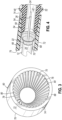
- a pair of radially outward protrusions 54 are positioned on the rear outer surface 50 and extend generally circumferentially thereabout, such that the protrusions 54 may be generally perpendicular to the lengths of the strength members 22.
- the purposes of the protrusions 54 are discussed in greater detail below.
- a weld collar 60 is
- the illustrated weld collar 60 includes a generally tube-shaped wall 68 defined by an at least partially tapered inner surface 70 and a generally cylindrical outer surface 72 and extending between first and second ends 74, 76.
- the inner surface 70 may be tapered radially inwardly in a direction from the first end 74 toward the second end 76.
- the tapering of the inner surface 70 may be complementary to the tapering of the rear outer surface 50 of the connector body 40.
- the inner surface 70 and the outer surface 50 may be tapered at a similar angle such that, when the weld collar 60 is advanced sufficiently over the connector body 40 (e.g., from the relative positioning shown in Fig.
- the inner surface 70 and outer surface 50 may mate and thereby provide one or more interfaces between the weld collar 60 and the connector body 40. Such interfaces may assist in providing an interference fit between the weld collar 60 and the connector body 40. The presence of the strength members 22 between the inner surface 70 and the outer surface 50 may also contribute to such an interference fit.
- the wall 68 of the weld collar 60 is shown as being generally circular in cross section, the wall 68 may be of any suitable cross section, such as planar or polygonal.
- the cross sectional shape of the wall 68 including one or both of the surfaces 70, 72 may be selected to correspond to a cross sectional shape of the connector body 40, such as the rear outer surface 50 thereof.
- a plurality of radially inward teeth 78 are positioned on the inner surface 70 of the weld collar 60 and extend longitudinally therealong in a circumferential array, such that the teeth 78 are parallel to the lengths of the strength members 22.
- the illustrated teeth 78 are each generally triangular in cross section and are spaced apart from each other to define a plurality of recesses 80 for receiving and/or separating the strength members 22 when the weld collar 60 is positioned over the strength members 22.
- the teeth 78 are spaced apart from each other in generally equal intervals such that the recesses 80 are generally uniform in size and shape. In this manner, the teeth 78 and recesses 80 may assist in evenly distributing the strength members 22 perimetrically (e.g., circumferentially) between the weld collar 60 and the connector body 40.
- the weld collar 60 is constructed of a material that is compatible with the material of the connector body 40 for ultrasonic welding.
- the weld collar 60 may be constructed of a plastic material, such as a thermoplastic material.
- the weld collar 60 and the connector body 40 may be constructed of a same material.
- the weld collar 60 and/or the connector body 40 may be constructed of a material compatible with the strength members 22 for mechanically attaching to the strength members 22, such as when partially melted and reset thereover.
- the ultrasonic welding horn 64 may be sized and shaped to generally conform to one or more features of the weld collar 60.
- the illustrated welding horn 64 includes a generally tube-shaped sleeve 82 having a pair of faces 84 and an inner surface 86.
- a slot 88 extends radially through the sleeve 82 along the length thereof and is sized to allow the sleeve 82 to pass radially over the cable 12, for example, so that the sleeve 82 may access the weld collar 60 in an axial direction along the cable 12.
- the sleeve 82 may be sized and configured for operative engagement between a face 84 of the sleeve 82 and an end, such as the second end 76, of the weld collar 60 (e.g., axial engagement), and/or for operative engagement between the inner surface 86 of the sleeve 82 and the outer surface 72 of the weld collar 60 (e.g., radial engagement).
- the welding horn 64 may be coupled to various components of an ultrasonic welding system, such as a transducer, a converter, a booster, an electronic ultrasonic generator, and/or a controller in a known manner for supplying ultrasonic energy to the welding horn 64.
- a method of coupling the connector 14 to the cable 12 by forming a composite 62 including the strength members 22 of the cable 12 is shown schematically.
- the strength members 22 are provided as discrete fibers 22a.
- the strength members 22 may be interwoven to form a generally unitary structure (e.g., as shown in Fig. 2 ).
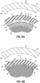
- the strength members 22a are exposed from the jacket 20 and positioned over the rear outer surface 50 of the connector body 40 ( Fig. 5A ).
- the strength members 22a may be advanced axially over the rear outer surface 50 of the connector body 40 (e.g., from the relative positioning shown in Fig.
- the strength members 22a may be advanced over both radial protrusions 54 (e.g., as shown in Fig. 4 ) to provide a desired length of the strength members 22a over the rear outer surface 50.
- one or both protrusions 54 e.g., the forwardmost protrusion 54
- the weld collar 60 and/or welding horn 64 may be positioned within the vicinity of the strength members 22a and/or connector body 40.
- the weld collar 60 is then positioned over the strength members 22a and rear outer surface 50 of the connector body 40 to provide one or more interfaces between the weld collar 60 and the connector body 40 ( Fig. 5B ).
- the weld collar 60 may be advanced axially over the strength members 22a (e.g., from the relative positioning shown in Fig. 2 ) and limited by the barrier 52 and/or by a resulting interference fit.
- the strength members 22a are captured or sandwiched between the rear outer surface 50 of the connector body 40 and the inner surface 70 of the weld collar 60.
- the teeth 78 may force the strength members 22a to become distributed in the recesses 80 in a generally even or uniform manner.
- each recess 80 is sized to receive two strength members 22a.
- each recess 80 may be sized to receive any suitable number of strength members 22a, such as a single strength member 22a or more than two strength members 22a, for evenly distributing the strength members 22a.
- the welding horn 64 is moved toward the weld collar 60 in the direction of the arrow A and positioned in operative engagement with the weld collar 60 for applying ultrasonic energy thereto ( Fig. 5C ). While the schematic illustration shows the welding horn 64 moving radially toward the weld collar 60 and positioned over the weld collar 60 such that the inner surface 86 of the welding horn 64 engages the outer surface 72 of the weld collar 60 in a radial direction, the welding horn 64 may be advanced axially over the weld collar 60 (e.g., from the relative positioning shown in Fig. 1 ) to achieve a similar operative engagement in the radial direction.
- the welding horn 64 may be advanced axially toward the weld collar 60 such that a face 84 of the welding horn 64 engages an end, such as the second end 76, of the weld collar 60 in an axial direction.
- the direction of operative engagement (e.g., radial or axial) may be influenced by the size and/or shape of the welding horn 64 relative to the weld collar 60.
- the welding horn 64 may press against the weld collar 60 radially and/or axially (e.g., depending on the direction of operative engagement) to apply a load for assisting in creating or maintaining the interfaces between the weld collar 60 and the connector body 40.
- an axial force applied by the welding horn 64 to the weld collar 60 may cause an applied normal force at the interfaces between the weld collar 60 and the connector body 40 due to the tapers of the inner surface 70 of the weld collar 60 and the outer surface 50 of the connector body 40, while a radial force applied by the welding horn 64 to the weld collar 60 (e.g., in a direction generally normal to the interfaces between the weld collar 60 and the connector body 40) may directly apply a normal force to the interfaces.
- the welding horn 64 applies a high frequency vibration, such as within a range of approximately 30 kHz to approximately 60 kHz, to the weld collar 60 for a short period of time, such as less than one second.
- the applied high frequency vibration may be approximately 40 kHz.
- the high frequency vibration is directed through the wall 68 of the weld collar 60 to the interfaces between the weld collar 60 and the connector body 40.
- the teeth 78 and/or radial protrusions 54 may assist in directing the ultrasonic energy to such interfaces.
- the ultrasonic energy causes localized partial melting of portions of the weld collar 60 and connector body 40 at or near the interfaces.
- These partially melted or molten portions may envelope portions of the strength members 22a.
- the teeth 78 and/or protrusions 54 may be at least partially melted and in their molten states may flow around and/or through the strength members 22a.
- the teeth 78 extending generally parallel to the strength members 22a may allow encapsulation of the strength members 22a as the teeth 78 partially melt and flow around the strength members 22a, while the protrusions 54 extending generally perpendicular to the strength members 22a may allow direct pressurized flow through the strength members 22a as the protrusions 54 partially melt.
- the welding horn 64 may be removed and the molten portions of the weld collar 60 and connector body 40 may be allowed to reset ( Fig. 5D ).
- the weld collar 60 and connector body 40 may be joined together and the strength members 22a may be firmly embedded in the reset material of the weld collar 60 and/or connector body 40, thereby forming a composite 62 of the strength members 22a and the surrounding material of the weld collar 60 and/or connector body 40.
- the resulting composite 62 including the strength members 22a firmly attaches the strength members 22a to both the weld collar 60 and the connector body 40 to securely couple the connector 14 to the cable 12.
- the need for crimping may be eliminated.
- improved retention and uniform distribution of the strength members 22a may be achieved while avoiding or eliminating mechanical stress on the connector body 40 that would otherwise be caused by crimping a conventional crimp body.
- the strength of the composite 62 including the strength members 22a may be sufficient to bear the load of normal qualification and service conditions for the fiber optic cable assembly 10.
- the composite 62 including the strength members 22a may eliminate the need to form metal around a plastic substrate, as is done for conventional crimping, thereby improving overall product durability and eliminating a hard to detect failure mode of the plastic substrate.
- the connector body 40 may be less susceptible to cracking than a conventional crimp body.
- the process to form the composite 62 may also be more robust than crimping, allowing for less expensive material handling and easier integration into automated systems.
- the weld collar 60 which may be constructed of molded plastic, may be cost effective as compared to a machined metal crimp band, such as a brass or aluminum crimp band.
- a slotted or partially slotted weld collar may include a slot extending axially along at least a portion of the wall of the weld collar and radially therethrough, and may allow for a radial strain to apply force during the welding process and/or may provide a mechanical spring force caused by advancing the weld collar over the connector body 40.
- a segmented weld collar may be provided by dividing the exemplary weld collar 60 into two or more segments which may be independently positioned and welded to the connector body 40, such as via a radially applied force on each segment. Such a radially applied force may be applied sequentially or simultaneously with a common welding horn 64, for example.
- the composite may include a portion of each of the independent segments.
- the teeth 78 are provided on the weld collar 60 and protrude radially inwardly, and the protrusions 54 may be are- provided on the connector body 40 and may protrude radially outwardly.
- the teeth 78 are provided on the connector body 40 and protrude radially outwardly, and the protrusions 54 may be provided on the weld collar 60 and may protrude radially inwardly.
Landscapes
- Physics & Mathematics (AREA)
- General Physics & Mathematics (AREA)
- Optics & Photonics (AREA)
- Mechanical Coupling Of Light Guides (AREA)
Claims (15)
- Ensemble de câble à fibre optique (10) comprenant :un câble à fibre optique (12) comprenant au moins un élément de renforcement (22) ;un connecteur de fibre optique (14) comprenant un corps de connecteur (40) ;un collier de soudage (60) positionné de manière telle que le au moins un élément de renforcement (22) est au moins partiellement piégé entre le corps de connecteur (40) et le collier de soudage (60) ; etun composite (62) comprenant une partie du au moins un élément de renforcement (22) et une partie du au moins un collier de soudage (60) ou du corps de connecteur (40), caractérisé en ce quele corps de connecteur (40) ou le collier de soudage (60) comprend une pluralité de dents s'étendant longitudinalement (78) définissant une pluralité d'évidements (80) pour recevoir le au moins un élément de renforcement (22).
- Ensemble de câble à fibre optique selon la revendication 1, dans lequel le composite (62) comprend une partie du collier de soudage (60) et une partie du corps de connecteur (40).
- Ensemble de câble à fibre optique selon la revendication 1 ou 2, dans lequel le composite (62) est formé en soudant par ultrasons le collier de soudage (60) au corps de connecteur (40).
- Ensemble de câble à fibre optique selon l'une quelconque des revendications 1-3, dans lequel le collier de soudage (60) comprend une matière plastique.
- Ensemble de câble à fibre optique selon l'une quelconque des revendications 1-4, dans lequel le corps de connecteur (40) ou le collier de soudage (60) comprend au moins une saillie s'étendant radialement (54).
- Ensemble de câble à fibre optique selon l'une quelconque des revendications 1-5, dans lequel le corps de connecteur (40) comprend une surface externe et le collier de soudage (60) comprend une surface interne configurée pour fournir un joint à ajustement serré avec la surface externe du corps de connecteur (40).
- Ensemble de câble à fibre optique selon l'une quelconque des revendications 1-5, dans lequel le corps de connecteur (40) comprend une surface externe conique, et dans lequel le collier de soudage (62) comprend une surface interne conique configurée pour fournir un joint à ajustement serré avec la surface externe conique du corps de connecteur (40).
- Ensemble de câble à fibre optique selon l'une quelconque des revendications 1-7, dans lequel le au moins un élément de renforcement (22) comprend du fil aramide.
- Ensemble de câble à fibre optique selon l'une quelconque des revendications 1-8, dans lequel le collier de soudage (60) est défini par une pluralité de segments indépendants, et dans lequel le composite (62) comprend une partie de chacun des segments indépendants.
- Procédé de couplage d'un câble à fibre optique (12) à un connecteur de fibre optique (14), le câble à fibre optique (12) comprenant au moins un élément de renforcement (22), le connecteur de fibre optique (14) comprenant un corps de connecteur (40), le procédé comprenant :positionner le au moins un élément de renforcement (22) sur le corps de connecteur (40) ;positionner un collier de soudage (60) sur le au moins un élément de renforcement (22) de manière telle que le au moins un élément de renforcement (22) est au moins partiellement piégé entre le corps de connecteur (40) et le collier de soudage (60) ; etformer un composite (62) comprenant une partie du au moins un élément de renforcement (22) et une partie du au moins un collier de soudage (60) ou du corps de connecteur ;
caractérisé en ce quele corps de connecteur (40) ou le collier de soudage (60) comprend une pluralité de dents s'étendant longitudinalement (78) définissant une pluralité d'évidements (80), et dans lequel positionner le collier de soudage sur le au moins un élément de renforcement (22) comprend répartir le au moins un élément de renforcement (22) parmi la pluralité d'évidements (80). - Procédé selon la revendication 10, dans lequel former le composite comprend fondre au moins partiellement le collier de soudage (60) ou le corps de connecteur (40).
- Procédé selon la revendication 10 ou 11, dans lequel former le composite (62) comprend souder par ultrasons le collier de soudage (60) au corps de connecteur (40) ;
dans lequel souder par ultrasons le collier de soudage (60) au corps de connecteur comprend engager un klaxon de soudure avec le collier de soudage (60). - Procédé selon la revendication 12, dans lequel souder par ultrasons le collier de soudage (60) au corps de connecteur comprend appliquer une vibration d'entre 30 kHz et 60 kHz au collier de soudage pendant moins d'une seconde.
- Procédé selon l'une quelconque des revendications 10-13, dans lequel former le composite comprend fondre au moins partiellement les dents de manière telle que les dents au moins partiellement fondues enveloppent une partie du au moins un élément de renforcement.
- Procédé selon l'une quelconque des revendications 10-14, dans lequel le corps de connecteur (40) ou le collier de soudage (60) comprend au moins une saillie s'étendant radialement (54), et dans lequel former le composite comprend fondre au moins partiellement la au moins une saillie pour diriger un flux pressurisé de la saillie au moins partiellement fondue à travers le au moins un élément de renforcement.
Applications Claiming Priority (2)
| Application Number | Priority Date | Filing Date | Title |
|---|---|---|---|
| US201862752433P | 2018-10-30 | 2018-10-30 | |
| PCT/US2019/055530 WO2020091967A1 (fr) | 2018-10-30 | 2019-10-10 | Ensemble câble à fibre optique comprenant un composite pour retenir des éléments de renfort et procédé associé |
Publications (2)
| Publication Number | Publication Date |
|---|---|
| EP3874310A1 EP3874310A1 (fr) | 2021-09-08 |
| EP3874310B1 true EP3874310B1 (fr) | 2023-11-22 |
Family
ID=68426820
Family Applications (1)
| Application Number | Title | Priority Date | Filing Date |
|---|---|---|---|
| EP19797876.0A Active EP3874310B1 (fr) | 2018-10-30 | 2019-10-10 | Ensemble câble à fibre optique comprenant un composite pour retenir des éléments de renfort et procédé associé |
Country Status (3)
| Country | Link |
|---|---|
| US (1) | US10955625B2 (fr) |
| EP (1) | EP3874310B1 (fr) |
| WO (1) | WO2020091967A1 (fr) |
Families Citing this family (1)
| Publication number | Priority date | Publication date | Assignee | Title |
|---|---|---|---|---|
| DE112023001300T5 (de) * | 2022-03-09 | 2025-01-02 | Huber+Suhner Ag | Optischer Verbinder |
Family Cites Families (14)
| Publication number | Priority date | Publication date | Assignee | Title |
|---|---|---|---|---|
| JPS60179708A (ja) * | 1984-02-28 | 1985-09-13 | Shin Kobe Electric Mach Co Ltd | 光フアイバコネクタの製造法 |
| JPS619611A (ja) * | 1984-06-25 | 1986-01-17 | Shin Kobe Electric Mach Co Ltd | 光フアイバコネクタの製造法 |
| JPH0615212B2 (ja) | 1987-09-18 | 1994-03-02 | 富士写真フイルム株式会社 | 熱可塑性樹脂部材の積層方法 |
| US5049274A (en) | 1988-01-11 | 1991-09-17 | Filtertek, Inc. | Friction welding process and filter formed thereby |
| US4920366A (en) * | 1989-05-31 | 1990-04-24 | Amp Incorporated | Construction of an optical fiber with a connector |
| US5186776A (en) | 1990-05-07 | 1993-02-16 | Foster-Miller, Inc. | Composite laminate translaminar reinforcement apparatus and method |
| US5923804A (en) * | 1997-03-31 | 1999-07-13 | Siecor Corporation | Fiber optic connector and an associated method of fabrication |
| JP2000241662A (ja) * | 1999-02-22 | 2000-09-08 | Seiko Instruments Inc | 光コネクタ及び光コネクタの製造方法 |
| US6419402B1 (en) * | 1999-12-13 | 2002-07-16 | Adc Telecommunications, Inc. | Fiber optic connector and method for assembling |
| US6672774B2 (en) | 2001-10-05 | 2004-01-06 | Corning Cable Systems Llc | Post-connectorization boot, connectorized fiber optic cable assembly including same, and related methods |
| US7537393B2 (en) * | 2005-06-08 | 2009-05-26 | Commscope, Inc. Of North Carolina | Connectorized fiber optic cabling and methods for forming the same |
| US8391658B2 (en) * | 2008-05-28 | 2013-03-05 | Adc Telecommunications, Inc. | Fiber optic cable with jacket embedded with reinforcing members |
| US8942528B2 (en) * | 2012-01-10 | 2015-01-27 | Corning Cable Systems Llc | Fiber optic cable sub-assemblies and methods of assembling |
| US10155341B2 (en) | 2014-04-25 | 2018-12-18 | Teijin Limited | Fiber-reinforced plastic joined body, method for producing fiber-reinforced plastic joined body, and fiber-reinforced molded article |
-
2019
- 2019-10-10 EP EP19797876.0A patent/EP3874310B1/fr active Active
- 2019-10-10 WO PCT/US2019/055530 patent/WO2020091967A1/fr not_active Ceased
- 2019-10-22 US US16/659,741 patent/US10955625B2/en not_active Expired - Fee Related
Also Published As
| Publication number | Publication date |
|---|---|
| US20200132945A1 (en) | 2020-04-30 |
| EP3874310A1 (fr) | 2021-09-08 |
| US10955625B2 (en) | 2021-03-23 |
| WO2020091967A1 (fr) | 2020-05-07 |
Similar Documents
| Publication | Publication Date | Title |
|---|---|---|
| EP2992372B1 (fr) | Assemblée d'un câble à fibre optique avec connecteur et procédé de son assemblage | |
| CA2669715C (fr) | Connecteur optique | |
| US7703990B1 (en) | Furcation bodies and fiber optic assemblies using the same | |
| US6960027B1 (en) | Method of fixing a ferrule to an optical waveguide | |
| US20140341511A1 (en) | Cable termination assembly and method for connectors | |
| CA2066767A1 (fr) | Connexion de cable | |
| CN101866034A (zh) | 加强型外部线路设备连接器用的单体电缆固位壳体 | |
| CN101806939A (zh) | 加强型外部线路设备连接器用的单体电缆固位壳体 | |
| JP5685298B2 (ja) | コネクタ付き光ファイバケーブル、コネクタ付き光ファイバケーブルの組立方法 | |
| CN102967902A (zh) | 光纤连接器 | |
| US20160363732A1 (en) | Fiber optic connector, fiber optic connector and cable assembly, and methods for manufacturing | |
| US11808983B2 (en) | Multi-fiber splice protector with compact splice-on furcation housing | |
| EP3874310B1 (fr) | Ensemble câble à fibre optique comprenant un composite pour retenir des éléments de renfort et procédé associé | |
| US9217828B2 (en) | Optical fiber protective tubing assembly | |
| US6854899B1 (en) | Ferrule for an optical fiber and process for fastening the ferrule on the optical fiber | |
| EP0008941B1 (fr) | Procédé pour fabriquer un terminal pour fibres optiques | |
| US11163117B2 (en) | Optical fiber cable and method for manufacturing the same | |
| WO2014031556A1 (fr) | Support de virole ayant une région adhésive accrue | |
| EP1493046B1 (fr) | Cable a fibres optiques flexible a bagues centrees, ajustees avec serrage | |
| JP4444270B2 (ja) | 光ファイバ接続部の補強構造、補強方法及び補強スリーブ |
Legal Events
| Date | Code | Title | Description |
|---|---|---|---|
| STAA | Information on the status of an ep patent application or granted ep patent |
Free format text: STATUS: UNKNOWN |
|
| STAA | Information on the status of an ep patent application or granted ep patent |
Free format text: STATUS: THE INTERNATIONAL PUBLICATION HAS BEEN MADE |
|
| PUAI | Public reference made under article 153(3) epc to a published international application that has entered the european phase |
Free format text: ORIGINAL CODE: 0009012 |
|
| STAA | Information on the status of an ep patent application or granted ep patent |
Free format text: STATUS: REQUEST FOR EXAMINATION WAS MADE |
|
| 17P | Request for examination filed |
Effective date: 20210428 |
|
| AK | Designated contracting states |
Kind code of ref document: A1 Designated state(s): AL AT BE BG CH CY CZ DE DK EE ES FI FR GB GR HR HU IE IS IT LI LT LU LV MC MK MT NL NO PL PT RO RS SE SI SK SM TR |
|
| DAV | Request for validation of the european patent (deleted) | ||
| DAX | Request for extension of the european patent (deleted) | ||
| GRAP | Despatch of communication of intention to grant a patent |
Free format text: ORIGINAL CODE: EPIDOSNIGR1 |
|
| STAA | Information on the status of an ep patent application or granted ep patent |
Free format text: STATUS: GRANT OF PATENT IS INTENDED |
|
| INTG | Intention to grant announced |
Effective date: 20230525 |
|
| GRAS | Grant fee paid |
Free format text: ORIGINAL CODE: EPIDOSNIGR3 |
|
| GRAA | (expected) grant |
Free format text: ORIGINAL CODE: 0009210 |
|
| STAA | Information on the status of an ep patent application or granted ep patent |
Free format text: STATUS: THE PATENT HAS BEEN GRANTED |
|
| P01 | Opt-out of the competence of the unified patent court (upc) registered |
Effective date: 20230919 |
|
| AK | Designated contracting states |
Kind code of ref document: B1 Designated state(s): AL AT BE BG CH CY CZ DE DK EE ES FI FR GB GR HR HU IE IS IT LI LT LU LV MC MK MT NL NO PL PT RO RS SE SI SK SM TR |
|
| REG | Reference to a national code |
Ref country code: GB Ref legal event code: FG4D |
|
| REG | Reference to a national code |
Ref country code: CH Ref legal event code: EP |
|
| REG | Reference to a national code |
Ref country code: DE Ref legal event code: R096 Ref document number: 602019041973 Country of ref document: DE |
|
| REG | Reference to a national code |
Ref country code: IE Ref legal event code: FG4D |
|
| REG | Reference to a national code |
Ref country code: LT Ref legal event code: MG9D |
|
| REG | Reference to a national code |
Ref country code: NL Ref legal event code: MP Effective date: 20231122 |
|
| PG25 | Lapsed in a contracting state [announced via postgrant information from national office to epo] |
Ref country code: GR Free format text: LAPSE BECAUSE OF FAILURE TO SUBMIT A TRANSLATION OF THE DESCRIPTION OR TO PAY THE FEE WITHIN THE PRESCRIBED TIME-LIMIT Effective date: 20240223 |
|
| PG25 | Lapsed in a contracting state [announced via postgrant information from national office to epo] |
Ref country code: IS Free format text: LAPSE BECAUSE OF FAILURE TO SUBMIT A TRANSLATION OF THE DESCRIPTION OR TO PAY THE FEE WITHIN THE PRESCRIBED TIME-LIMIT Effective date: 20240322 |
|
| PG25 | Lapsed in a contracting state [announced via postgrant information from national office to epo] |
Ref country code: LT Free format text: LAPSE BECAUSE OF FAILURE TO SUBMIT A TRANSLATION OF THE DESCRIPTION OR TO PAY THE FEE WITHIN THE PRESCRIBED TIME-LIMIT Effective date: 20231122 |
|
| REG | Reference to a national code |
Ref country code: AT Ref legal event code: MK05 Ref document number: 1634331 Country of ref document: AT Kind code of ref document: T Effective date: 20231122 |
|
| PG25 | Lapsed in a contracting state [announced via postgrant information from national office to epo] |
Ref country code: NL Free format text: LAPSE BECAUSE OF FAILURE TO SUBMIT A TRANSLATION OF THE DESCRIPTION OR TO PAY THE FEE WITHIN THE PRESCRIBED TIME-LIMIT Effective date: 20231122 |
|
| PG25 | Lapsed in a contracting state [announced via postgrant information from national office to epo] |
Ref country code: AT Free format text: LAPSE BECAUSE OF FAILURE TO SUBMIT A TRANSLATION OF THE DESCRIPTION OR TO PAY THE FEE WITHIN THE PRESCRIBED TIME-LIMIT Effective date: 20231122 |
|
| PG25 | Lapsed in a contracting state [announced via postgrant information from national office to epo] |
Ref country code: ES Free format text: LAPSE BECAUSE OF FAILURE TO SUBMIT A TRANSLATION OF THE DESCRIPTION OR TO PAY THE FEE WITHIN THE PRESCRIBED TIME-LIMIT Effective date: 20231122 |
|
| PG25 | Lapsed in a contracting state [announced via postgrant information from national office to epo] |
Ref country code: NL Free format text: LAPSE BECAUSE OF FAILURE TO SUBMIT A TRANSLATION OF THE DESCRIPTION OR TO PAY THE FEE WITHIN THE PRESCRIBED TIME-LIMIT Effective date: 20231122 Ref country code: LT Free format text: LAPSE BECAUSE OF FAILURE TO SUBMIT A TRANSLATION OF THE DESCRIPTION OR TO PAY THE FEE WITHIN THE PRESCRIBED TIME-LIMIT Effective date: 20231122 Ref country code: IS Free format text: LAPSE BECAUSE OF FAILURE TO SUBMIT A TRANSLATION OF THE DESCRIPTION OR TO PAY THE FEE WITHIN THE PRESCRIBED TIME-LIMIT Effective date: 20240322 Ref country code: GR Free format text: LAPSE BECAUSE OF FAILURE TO SUBMIT A TRANSLATION OF THE DESCRIPTION OR TO PAY THE FEE WITHIN THE PRESCRIBED TIME-LIMIT Effective date: 20240223 Ref country code: ES Free format text: LAPSE BECAUSE OF FAILURE TO SUBMIT A TRANSLATION OF THE DESCRIPTION OR TO PAY THE FEE WITHIN THE PRESCRIBED TIME-LIMIT Effective date: 20231122 Ref country code: BG Free format text: LAPSE BECAUSE OF FAILURE TO SUBMIT A TRANSLATION OF THE DESCRIPTION OR TO PAY THE FEE WITHIN THE PRESCRIBED TIME-LIMIT Effective date: 20240222 Ref country code: AT Free format text: LAPSE BECAUSE OF FAILURE TO SUBMIT A TRANSLATION OF THE DESCRIPTION OR TO PAY THE FEE WITHIN THE PRESCRIBED TIME-LIMIT Effective date: 20231122 Ref country code: PT Free format text: LAPSE BECAUSE OF FAILURE TO SUBMIT A TRANSLATION OF THE DESCRIPTION OR TO PAY THE FEE WITHIN THE PRESCRIBED TIME-LIMIT Effective date: 20240322 |
|
| PG25 | Lapsed in a contracting state [announced via postgrant information from national office to epo] |
Ref country code: SE Free format text: LAPSE BECAUSE OF FAILURE TO SUBMIT A TRANSLATION OF THE DESCRIPTION OR TO PAY THE FEE WITHIN THE PRESCRIBED TIME-LIMIT Effective date: 20231122 Ref country code: RS Free format text: LAPSE BECAUSE OF FAILURE TO SUBMIT A TRANSLATION OF THE DESCRIPTION OR TO PAY THE FEE WITHIN THE PRESCRIBED TIME-LIMIT Effective date: 20231122 Ref country code: PL Free format text: LAPSE BECAUSE OF FAILURE TO SUBMIT A TRANSLATION OF THE DESCRIPTION OR TO PAY THE FEE WITHIN THE PRESCRIBED TIME-LIMIT Effective date: 20231122 Ref country code: NO Free format text: LAPSE BECAUSE OF FAILURE TO SUBMIT A TRANSLATION OF THE DESCRIPTION OR TO PAY THE FEE WITHIN THE PRESCRIBED TIME-LIMIT Effective date: 20240222 Ref country code: LV Free format text: LAPSE BECAUSE OF FAILURE TO SUBMIT A TRANSLATION OF THE DESCRIPTION OR TO PAY THE FEE WITHIN THE PRESCRIBED TIME-LIMIT Effective date: 20231122 Ref country code: HR Free format text: LAPSE BECAUSE OF FAILURE TO SUBMIT A TRANSLATION OF THE DESCRIPTION OR TO PAY THE FEE WITHIN THE PRESCRIBED TIME-LIMIT Effective date: 20231122 |
|
| PG25 | Lapsed in a contracting state [announced via postgrant information from national office to epo] |
Ref country code: DK Free format text: LAPSE BECAUSE OF FAILURE TO SUBMIT A TRANSLATION OF THE DESCRIPTION OR TO PAY THE FEE WITHIN THE PRESCRIBED TIME-LIMIT Effective date: 20231122 |
|
| PG25 | Lapsed in a contracting state [announced via postgrant information from national office to epo] |
Ref country code: CZ Free format text: LAPSE BECAUSE OF FAILURE TO SUBMIT A TRANSLATION OF THE DESCRIPTION OR TO PAY THE FEE WITHIN THE PRESCRIBED TIME-LIMIT Effective date: 20231122 |
|
| PG25 | Lapsed in a contracting state [announced via postgrant information from national office to epo] |
Ref country code: SK Free format text: LAPSE BECAUSE OF FAILURE TO SUBMIT A TRANSLATION OF THE DESCRIPTION OR TO PAY THE FEE WITHIN THE PRESCRIBED TIME-LIMIT Effective date: 20231122 |
|
| PG25 | Lapsed in a contracting state [announced via postgrant information from national office to epo] |
Ref country code: SM Free format text: LAPSE BECAUSE OF FAILURE TO SUBMIT A TRANSLATION OF THE DESCRIPTION OR TO PAY THE FEE WITHIN THE PRESCRIBED TIME-LIMIT Effective date: 20231122 Ref country code: SK Free format text: LAPSE BECAUSE OF FAILURE TO SUBMIT A TRANSLATION OF THE DESCRIPTION OR TO PAY THE FEE WITHIN THE PRESCRIBED TIME-LIMIT Effective date: 20231122 Ref country code: RO Free format text: LAPSE BECAUSE OF FAILURE TO SUBMIT A TRANSLATION OF THE DESCRIPTION OR TO PAY THE FEE WITHIN THE PRESCRIBED TIME-LIMIT Effective date: 20231122 Ref country code: IT Free format text: LAPSE BECAUSE OF FAILURE TO SUBMIT A TRANSLATION OF THE DESCRIPTION OR TO PAY THE FEE WITHIN THE PRESCRIBED TIME-LIMIT Effective date: 20231122 Ref country code: EE Free format text: LAPSE BECAUSE OF FAILURE TO SUBMIT A TRANSLATION OF THE DESCRIPTION OR TO PAY THE FEE WITHIN THE PRESCRIBED TIME-LIMIT Effective date: 20231122 Ref country code: DK Free format text: LAPSE BECAUSE OF FAILURE TO SUBMIT A TRANSLATION OF THE DESCRIPTION OR TO PAY THE FEE WITHIN THE PRESCRIBED TIME-LIMIT Effective date: 20231122 Ref country code: CZ Free format text: LAPSE BECAUSE OF FAILURE TO SUBMIT A TRANSLATION OF THE DESCRIPTION OR TO PAY THE FEE WITHIN THE PRESCRIBED TIME-LIMIT Effective date: 20231122 |
|
| REG | Reference to a national code |
Ref country code: DE Ref legal event code: R097 Ref document number: 602019041973 Country of ref document: DE |
|
| PLBE | No opposition filed within time limit |
Free format text: ORIGINAL CODE: 0009261 |
|
| STAA | Information on the status of an ep patent application or granted ep patent |
Free format text: STATUS: NO OPPOSITION FILED WITHIN TIME LIMIT |
|
| PG25 | Lapsed in a contracting state [announced via postgrant information from national office to epo] |
Ref country code: SI Free format text: LAPSE BECAUSE OF FAILURE TO SUBMIT A TRANSLATION OF THE DESCRIPTION OR TO PAY THE FEE WITHIN THE PRESCRIBED TIME-LIMIT Effective date: 20231122 |
|
| 26N | No opposition filed |
Effective date: 20240823 |
|
| PG25 | Lapsed in a contracting state [announced via postgrant information from national office to epo] |
Ref country code: SI Free format text: LAPSE BECAUSE OF FAILURE TO SUBMIT A TRANSLATION OF THE DESCRIPTION OR TO PAY THE FEE WITHIN THE PRESCRIBED TIME-LIMIT Effective date: 20231122 |
|
| REG | Reference to a national code |
Ref country code: DE Ref legal event code: R119 Ref document number: 602019041973 Country of ref document: DE |
|
| REG | Reference to a national code |
Ref country code: CH Ref legal event code: PL |
|
| GBPC | Gb: european patent ceased through non-payment of renewal fee |
Effective date: 20241010 |
|
| PG25 | Lapsed in a contracting state [announced via postgrant information from national office to epo] |
Ref country code: MC Free format text: LAPSE BECAUSE OF FAILURE TO SUBMIT A TRANSLATION OF THE DESCRIPTION OR TO PAY THE FEE WITHIN THE PRESCRIBED TIME-LIMIT Effective date: 20231122 |
|
| PG25 | Lapsed in a contracting state [announced via postgrant information from national office to epo] |
Ref country code: DE Free format text: LAPSE BECAUSE OF NON-PAYMENT OF DUE FEES Effective date: 20250501 |
|
| PG25 | Lapsed in a contracting state [announced via postgrant information from national office to epo] |
Ref country code: GB Free format text: LAPSE BECAUSE OF NON-PAYMENT OF DUE FEES Effective date: 20241010 |
|
| PG25 | Lapsed in a contracting state [announced via postgrant information from national office to epo] |
Ref country code: LU Free format text: LAPSE BECAUSE OF NON-PAYMENT OF DUE FEES Effective date: 20241010 Ref country code: BE Free format text: LAPSE BECAUSE OF NON-PAYMENT OF DUE FEES Effective date: 20241031 |
|
| PG25 | Lapsed in a contracting state [announced via postgrant information from national office to epo] |
Ref country code: FR Free format text: LAPSE BECAUSE OF NON-PAYMENT OF DUE FEES Effective date: 20241031 |
|
| PG25 | Lapsed in a contracting state [announced via postgrant information from national office to epo] |
Ref country code: CH Free format text: LAPSE BECAUSE OF NON-PAYMENT OF DUE FEES Effective date: 20241031 |
|
| REG | Reference to a national code |
Ref country code: BE Ref legal event code: MM Effective date: 20241031 |
|
| PG25 | Lapsed in a contracting state [announced via postgrant information from national office to epo] |
Ref country code: FI Free format text: LAPSE BECAUSE OF FAILURE TO SUBMIT A TRANSLATION OF THE DESCRIPTION OR TO PAY THE FEE WITHIN THE PRESCRIBED TIME-LIMIT Effective date: 20231122 |
|
| PG25 | Lapsed in a contracting state [announced via postgrant information from national office to epo] |
Ref country code: IE Free format text: LAPSE BECAUSE OF NON-PAYMENT OF DUE FEES Effective date: 20241010 |
|
| PG25 | Lapsed in a contracting state [announced via postgrant information from national office to epo] |
Ref country code: CY Free format text: LAPSE BECAUSE OF FAILURE TO SUBMIT A TRANSLATION OF THE DESCRIPTION OR TO PAY THE FEE WITHIN THE PRESCRIBED TIME-LIMIT; INVALID AB INITIO Effective date: 20191010 |
|
| PG25 | Lapsed in a contracting state [announced via postgrant information from national office to epo] |
Ref country code: HU Free format text: LAPSE BECAUSE OF FAILURE TO SUBMIT A TRANSLATION OF THE DESCRIPTION OR TO PAY THE FEE WITHIN THE PRESCRIBED TIME-LIMIT; INVALID AB INITIO Effective date: 20191010 |